1
MMH900 Series Statistical
Multiplexer
User Guide
User Guide
S000315A Revision A
MultiMux (#MMH904Ca) (#MMH908Ca)
This publication may not be reproduced, in whole or in part, without prior
expressed written permission from Multi-Tech Systems, Inc. All rights
reserved.
Copyright © 2003, by Multi-Tech Systems, Inc.
Multi-Tech Systems, Inc. makes no representations or warranties with
respect to the contents hereof and specifically disclaims any implied
warranties of merchantability or fitness for any particular purpose.
Furthermore, Multi-Tech Systems, Inc. reserves the right to revise this
publication and to make changes from time to time in the content hereof
without obligation of Multi-Tech Systems, Inc. to notify any person or
organization of such revisions or changes.
Record of Revisions
Revision Date
A
11/01/03
Description
Initial release of MultiMux MMH904/908C for
publication on CD.
TRADEMARK
Trademark of Multi-Tech Systems, Inc. are as follows: MultiMux,
MultiModem and the Multi-Tech logo.
Multi-Tech Systems, Inc.
2205 Woodale Drive
Mounds View, Minnesota 55112
(763) 785-3500 or (800) 328-9717
Fax (763) 785-9874
Tech Support (800) 972-2439
Internet Address: http://www.multitech.com
Contents
Chapter 1 - Introduction & Description ................................ 8
1.1
Introduction .................................................................................... 9
1.2
About This Manual ......................................................................... 9
1.3
Background ................................................................................... 11
1.3.1 Description of Statistical Multiplexing ................................... 12
1.3.1.1 Statistical Multiplexing .......................................................... 12
1.4
Product Description ....................................................................... 14
1.5
System Features ........................................................................... 17
1.5.1 Response Time Control ........................................................ 17
1.5.2 Dynamic Buffering ................................................................ 17
1.5.3 Flow Control ......................................................................... 18
1.5.4 Diagnostics .......................................................................... 18
1.5.5 Downline Parameter Loading ............................................... 18
1.5.6 Operational Statistics and Auto-Reporting ............................ 19
1.5.7 Parameter Memory .............................................................. 19
1.5.8 Channel Flexibility ................................................................ 19
1.5.9 Command Modem ................................................................ 19
1.5.10 Composite Link .................................................................... 20
1.6
FCC Regulations for Telephone Line Interconnection ................... 21
1.7
DOC Terminal Equipment .............................................................. 23
1.8
Specifications ................................................................................ 24
1.8.1 Channels .............................................................................. 24
1.8.2 System Control ..................................................................... 24
1.8.3 Composite LInk .................................................................... 25
1.8.4 33,600 bps Link Modem ....................................................... 25
1.8.5
56,000 bps DSU .................................................................. 25
1.8.6 ISDN Terminal Adapter ......................................................... 26
1.8.7 Command Modem ................................................................ 26
1.8.8 Electrical/Physical ................................................................ 26
Chapter 2 - Configuration ..................................................... 27
2.1
Introduction .................................................................................... 28
2.2
Configuration 1 .............................................................................. 29
2.3
Configuration 2 .............................................................................. 31
2.4
Configuration 3 .............................................................................. 32
Chapter 3 - Front & Rear Panel Descriptions..................... 34
3.1
Introduction .................................................................................... 35
3.2
Front Panel .................................................................................... 35
3.3
LED Indicators .............................................................................. 36
3.4
Back Panel .................................................................................... 40
3.4.1 ON/OFF Switch .................................................................... 40
3.4.2 Power Connector ................................................................. 40
3.4.3 COMMAND MODEM DIAL-UP Connector .......................... 40
3.4.4 COMMAND PORT Connector .............................................. 40
3.4.5 COMPOSITE LINK INTERNAL MODEM DIAL-UP Connector 40
3.4.6 COMPOSITE LINK INTERNAL MODEM LEASED Connector 41
3.4.7 COMPOSITE LINK INTERNAL DIGITAL DSU Connector .... 41
3.4.8 COMPOSITE LINK EXTERNAL RS232C/V.35 Connector ... 41
3.4.9 CHANNEL 1 - CHANNEL 8 Connectors ............................... 41
3.5
Switches/Jumper/Shunt ................................................................. 42
3.5.1 8-Position DIP Switch ........................................................... 42
3.5.2 4-Position DIP Switch ........................................................... 43
3.5.3 144RKWL/OtherJumper ....................................................... 44
3.5.4 V.24/V.35 Shunt .................................................................... 44
3.5.5 V.29/V.33 Shunt and 2834 Shunt .......................................... 44
Chapter 4- Installation ........................................................... 45
4.1
Introduction .................................................................................... 46
4.2
Safety Warnings ............................................................................ 46
4.3
Unpacking ...................................................................................... 46
4.4
Installation ..................................................................................... 47
Chapter 5 - Commands ......................................................... 52
5.1
Introduction .................................................................................... 53
5.2
Command Description ................................................................... 58
5.2.1 General Commands ............................................................. 58
5.2.2 Channel Parameter Commands ........................................... 65
5.2.3 Composite Link Commands ................................................. 74
5.2.4 Composite Link Format Commands ..................................... 78
5.2.5 Internal 9600/14.4K Composite Link Modem Commands ..... 81
5.2.6 Internal MMH2834 Modem Configuration Commands .......... 84
5.2.7
5.2.8
5.2.9
Internal Composite Link DSU Commands ............................ 86
Test Commands ................................................................... 87
Command Modem commands ............................................. 89
Chapter 6- Operating Procedures ....................................... 90
6.1
Introduction .................................................................................... 91
6.2
MultiMux Operating Procedures .................................................... 91
6.3
Command Modem Operating Procedures ..................................... 95
Chapter 7 - Troubleshooting ................................................ 97
7.1
Introduction .................................................................................... 98
7.2
Importance of Composite Statistics ............................................... 98
7.3
Test Cables .................................................................................... 99
7.4
Troubleshooting Guide .................................................................. 101
7.5
Channel Device Testing ................................................................. 107
7.6
Local Modem and Communications Line Testing .......................... 108
7.7
MultiMux Functional Testing Procedures ....................................... 110
Chapter 8- Service, Warranty, & Technical Support ......... 112
8.1
Introduction .................................................................................... 113
8.2
Warranty ........................................................................................ 113
8.3
Repair Procedures for U.S. and Canadian Customers .................. 114
8.4
Repair Procedures for International Customers (Outside U.S.A. and
Canada) ............................................................................................ 115
8.5
Repair Procedures for International Distributors ............................ 116
8.6
Online Warranty Registration ......................................................... 116
Appendices .......................................................................... 117
Appendix A .............................................................................................. 118
Ascii Character Code/Hex/Decimal Conversion Chart ...................... 118
Appendix B
RS232C Interface Specification ........................................................ 119
Appendix C .............................................................................................. 121
Cabling Diagrams .............................................................................. 121
Appendix D .............................................................................................. 125
Command Modem Commands ......................................................... 125
Appendix E Command Modem S-Register Function .............................. 138
Appendix F .............................................................................................. 143
Flow Control Background .................................................................. 143
Appendix G ............................................................................................. 146
MMH2834 S-Registers ...................................................................... 146
Appendix H .............................................................................................. 149
Dial Back-up ...................................................................................... 149
Appendix I ............................................................................................... 150
Testing Your MMH2834 ..................................................................... 150
I.1 Introduction ................................................................................ 150
I.2 Local Analog Loopback Test/V.54 Loop 3 .................................. 151
I.3
Digital Loopback Test/V.54 Loop 2 (Loc/Man) ...................... 152
I.4 Digital Loopback Test/V.54 Loop (Rem/Auto) ............................ 154
I.5
Synchronous Mode Testing ................................................. 156
I.6
Local Analog Loopback Test (Sync Mode) ........................... 157
I.7
Digital Loopback Test (Loc/Man) Sync Mode ...................... 158
I.8
Digital Loopback Test (Rem/Auto)(Sync Mode) ................... 159
Appendix J - Internal MMH2834 Composite Link Modem Commands .... 160
J.1.1 Dialing Action Commands ........................................................ 163
J.1.2 Dial Modifier Commands ...................................................... 165
J.1.3 Phone Number Memory Commands .................................... 168
J.1.4 Configuration and Default Storage Commands .................... 170
J.1.5 Command Response (Result Code) Commands ..................... 172
J.1.6 Phone Line Conditioning Commands ...................................... 176
J.1.7 RS232C Interface Control Commands ..................................... 177
J.1.8 Error Correction Commands ................................................ 178
J.1.9
Compression and Maximum Block Size Commands ............ 180
J.1.10 Speed Conversion Commands ............................................. 181
J.1.11
Immediate Action Commands ............................................... 183
Glossary ............................................................................... 185
Index ..................................................................................... 195
Chapter 1 - Introduction &
Description
Chapter 1 - Introduction & Description
1.1
Introduction
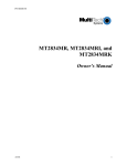
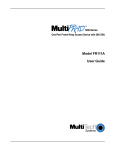
Congratulations! Your new MultiMux MMH900 series is one of the finest
statistical multiplexers on the market today. The MultiMux is completely
software driven and is controlled by you through its command port. This
gives you great flexibility and ease of operation. This Owner’s Manual
will help you to install and use your MultiMux, and also provide you with
a valuable information resource in the future.
Command Modem
CD
RCV
XMT
OH
DTR
External Composite Link
CD
RCV
XMT
CTS
V.35
Channel Five
RCV
XMT
Channel one
RCV
XMT
Channel Six
RCV
XMT
Channel Two
RCV
XMT
Channel Seven
RCV
XMT
Channel Three
RCV
XMT
R
E
T
R
A
N
S
M
IT
Channel Eight
RCV
2
3
F
L
O
C
T
R
L
R
C
V
L
I
N
K
A
L
A
R
M
R
E
M
O
T
E
D
W
N
T
E
S
T
A
S
Y
N
C
M
O
D
E
L
I
N
K
INTERNAL LINK DEVICE
(Modems)
M
V
M
2
H
9
I
2
/
D
S
V
8
S
3
D
3
U
3
N
4
MultiTech
Systems
XMT
MultiMux
Statistical Multiplexer
Internal Composite Link
Channel Four
RCV
BUFFER
FULLNESS
LEVEL
1
XMT
ISDN
MMH2834
DSU
V29/V33
CD RCV XMT CTS 28.8
CD RCV XMT CTS 56
CD RCV XMT CTS
24.0
19.2
19.2
RTS
14.4
NS
OH
OOS
TR
TM
EC
DBUP
Figure 1-1. MultiMux MMH900 Series
1.2
About This Manual
eThis manual is comprised of eight chapters. There are also several
appendices at the end of the manual, most of which is a condensed
version of the information contained in the chapters. These appendices
can be used as a quick reference. The information contained in each
chapter is as follows:
Chapter 1 - Introduction
This chapter is an introduction to the world of multiplexing. Since you
have already acquired the MultiMux, you may have an extensive
background in multiplexing. In which case, this introduction will provide a
good review.
Chapter 2 - Configuration
This chapter defines the configurations of the MMH900 series and
provides some typical examples of how the MultiMux is configured. The
MMH900 series is available in two models; the four and eight channel
units with an internal command modem, various composite link modems
supporting synchronous or asynchronous communications. The typical
examples explain how the MultiMux can be used in various
environments.
8
Chapter 1 - Introduction & Description
Chapter 3 - Front and Rear Panel Descriptions
Chapter 3 describes the front panel indicators, the switches and jumpers
within the cabinet and the rear panel connections. The front panel
indicators are described in the various groups depending on the
configuration of the MultiMux. Indicator groups are active depending on
how the MultiMux is used. The front panel is the same for all models
and contains some indicators for future enhancements. The back panel
provides all the cable connections for the early released models with the
addition of cable connections for future releases.
Chapter 4 - Installation
Chapter 4 provides the procedures for unpacking, installing and cabling
your MultiMux. After your MultiMux is cabled, an initial power on
procedure is provided for you to display and modify the channel and link
parameters to fit your configuration.
Chapter 5 - Commands
The MultiMux is software-driven and controlled through its command port
and the supervisory console. This chapter describes the AT commands
and the impact each has on your system’s operation.
Chapter 6 - Operating Procedures
Chapter 6 provides the operational information for your MultiMux. The
MultiMux operating procedures address the channel and composite link
parameters. The command modem operating procedures address the
command modem access, dialing, and remote access procedures.
Chapter 7 - Troubleshooting Procedures
This chapter is a guide to troubleshooting your MultiMux. It contains a
listing of error conditions, probable causes and suggested fixes or steps
designed to isolate the failing unit in your communications network.
Chapter 8- Service, Warranty and Tech Support
Chapter 8 provides instructions on getting service for the MultiMux at the
factory, a statement of the limited warranty, information about our user
bulletin board service, and space for recording information about your
multiplexer prior to calling Multi-Tech's Technical Support.
9
Chapter 1 - Introduction & Description
1.3
Background
Any data communications environment that has more than one
asynchronous line going between common locations can probably
benefit by installing a pair of statistical multiplexers (stat muxes). A stat
mux performs the function of combining several asynchronous data
communication channels into one composite signal that can be
transmitted between two locations more inexpensively than the cost of
the individual lines.
Figure 1-2 shows a simple communications network. Individual users
connect to asynchronous channels and the composite (or aggregate)
communications line between the two locations is the "link". Link
protocol is the communications discipline used between the two
multiplexers and typically operates at a speed higher than the individual
asynchronous units connected to each multiplexer.
Figure 1-2. Simple Communications Network
One reason that a stat mux works is that typically an asynchronous
terminal device is not used to its capacity. Studies show that as little as
10 to 15% utilization of such lines is a common occurrence. These
percentages indicate that the most efficient combination of lines in a
muxed asynchronous environment is between four and eight lines.
Although the primary reason for installing a mux is to save on
communications costs, two other benefits are also present. One is the
inherent error correction existing in muxed data and the other is data
security. Since a mux functions by taking individual asynchronous data
and transmitting it as data packets, there is an error detection and
retransmission scheme built in. Error correction is so vital in many
transmission types, such as graphic data and program transmission, that
many muxes are used mainly for their error correction capabilities.
The other benefit is data security which is achieved by the fact that the
individual data streams are encrypted into a single communication line
10
Chapter 1 - Introduction & Description
on one end of the link and then broken up into individual components on
the other end. Someone wishing to "tap" into a muxed signal must not
only have the link protocol which is typically a proprietary version of High
Level Data Link Control (HDLC), but must also know the individual
channel assignment schemes and data formats.
1.3.1
Description of Statistical Multiplexing
A statistical multiplexer (also known as a stat mux) is a device that
allows several other devices (usually computer terminals or PCs) to
communicate over a single transmission line. Sometimes called
concentrators, they take data from different devices and combine it into a
single stream that can be transmitted, via a modem, to an identical
multiplexer at another location, where the stream is then separated back
into its original form. Physically, a mux looks like a box with a bunch of
serial ports and some LEDs. The most typical task of the MultiMux is to
connect a group of PCs or terminals at one site to a mini or mainframe
computer at another site via a single set of modems rather than using
individual modems for each PC or terminal.
1.3.1.1 Statistical Multiplexing
Statistical multiplexing is sometimes referred to as statistical timedivision multiplexing (STDM). The use of the voice-grade phone line (or
any other communications link) is based not on peak data rates, but on
effective (or average) data rates.
During the peaks, when the sum of the data rates of the channels being
served exceeds the data rate of the composite link, a statistical
multiplexer saves the excess data in buffers (in effect, allowing individual
channel buffers to expand). The buffers are emptied as soon as the
activity falls off. The proper allocation of buffer space, plus the
implementation of “flow control” and “pacing” techniques to
accommodate unusually high peaks, allows the use of composite link
speeds that are less than the sum of the individual channel speeds.
In effect, a statistical multiplexer services only active channels. However,
the efficiency thus realized is not the only benefit of the technique.
Because composite link activity need not be synchronized with the
activity on the individual channels, there is considerable flexibility in the
choice of the composite channel protocol and speed. The use of a
synchronous protocol like HDLC provides for error detection and
retransmission over the composite link. Thus, asynchronous terminals,
which have no inherent error-recovery capability, can enjoy end-to-end
data integrity.
11
Chapter 1 - Introduction & Description
1.3.1.2 Communications
The basic functions of multiplexing are to make communications more
efficient, to provide a means of improving accuracy of asynchronous
communications by using synchronous techniques, and to improve data
security by encrypting several data streams into one coded link.
The channel devices can be any asynchronous RS232 compatible units,
from “dumb terminals” to personal computers running asynchronous
communications software. The connection between the channel devices
and the MultiMux is made through an RS232 interface cable.
Asynchronous modems (long haul or short haul), asynchronous modem
emulators and asynchronous line drivers (DCE devices) can be used in
this connection (up to 38.4K bps) to extend the distance between the
channel devices and the MultiMux.
The connection between the two MultiMuxes is the composite link, and
can be up to 128K bps. Using an internal modem, ISDN terminal
adapter, DSU, or external device, the MultiMux can be connected to
different types of communications links, such as a dial-up line, leased
line, Basic Rate Interface (BRI) ISDN service, or a DDS network. If an
external link device is used the MultiMux can communicate with it using
either the RS232 or V.35 standard.
12
Chapter 1 - Introduction & Description
1.4
Product Description
There are two basic models of MultiMux MMH900 series available: a
four channel and eight channel units with internal command modem,
optional composite link modems and a command port. The four channel
MultiMux MMH904 connects four async devices to asynchronous
channels that transfer data at a channel speed of up to 38.4K bits per
second (bps). The eight channel MultiMux MMH908 connects eight
async devices. The composite link of the MultiMux MMH900 series can
be configured for various dial-up and lease line modems, a Digital
Service Unit (DSU) for digital communications over a Digital Data
Service (DDS) or dedicated network, or an ISDN terminal adapter for
Basic Rate Interface Service. The command port allows you to
configure the MultiMux MMH900 series for your channel configuration,
internal hardware and composite link configuration.
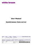
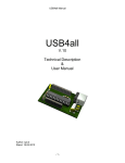
A simplified block diagram of a MultiMux network is shown in Figure 1-3
to give you a pictorial view of a complete network. The MultiMux
represented in the figure is a MultiMux MMH904 connected to four async
devices on CHANNEL 1 through CHANNEL 4. The workstation
connected to the COMMAND PORT is the supervisory console in which
you can communicate with the command processor or command
modem. If a remote connection is needed to the command modem, a
separate DIAL-UP connection is provided. The composite link can be
configured for an internal 28.8K bps dial-up/leased line modem, internal
DSU for digital communications over a digital data service (DDS)
network or an ISDN terminal adapter for Basic Rate Interface Service. It
can also be configured for external synchronous link device with either
V.24 or V.35 interface.
Composite
Link Data
Channel
4
Channel
Data
Channel
2
Channel
Data
Lease Modem
AT Commands
DSU
Command
Processor
C
o
mL
p i
o n
s k
i
t
e
Dial-Up Modem
Composite
Link
Composite
Link
PDN
Lease Modem
Digital
I/O
AT Commands
Channel
1
Command
Port
Dial-Up Modem
Data
Processor
I/O
Channel
3
Dial-up
Line
Dial-up
Line
ATCommands
Command
Modem
AT Commands
Dial-up
PDN
Workstation PC
MultiMux 900 Series
Workstation PC
Figure 1-3. MultiMux MMH900 Series Block Diagram
To setup a MultiMux MMH900 series, the async devices have to be
connected to the channels, the composite link connected to the public
data network (PDN) and the MultiMux has to be configured for the
13
Chapter 1 - Introduction & Description
channel devices and the composite link. The async devices are
connected to CHANNEL 1 through CHANNEL 4 connectors on the back
panel of the MultiMux MMH904 with an RS232 cable. The MultiMux
MMH908 has four additional channel connectors for connecting up to
eight devices.
A number of internal and external composite link devices can be used to
connect the MultiMux to the PDN. The MMH900 series has an internal
28,800 bps composite link modem or an internal 56,000 bps DSU. The
modem is connected to the PDN through the INTERNAL COMPOSITE
LINK LEASED MODEM connector on the back panel of the MultiMux.
The internal DSU is connected to a DDS or dedicated network through
the COMPOSITE LINK DIGITAL DSU connector on the back panel.
The supervisory console is connected to the MultiMux through the
COMMAND PORT connector on the back panel. The supervisory
console connection is also an RS232 connection. This completes a
typical hardware setup for a MultiMux. Now the MultiMux has to be
configured to talk to the channel devices and communicate over the
composite link.
Configuration of a MultiMux is accomplished through a combination of
setting DIP switches behind the front panel and software commands
entered through the supervisory console. The DIP switches determine
whether the MultiMux is a four or eight channel multiplexer, whether the
composite link device is an internal modem or DSU or an external
device, whether or not the command modem will accept remote access,
etc. The DIP switches control the hardware setup and the operating
setup is controlled through software commands. The software
commands are entered at a terminal connected to the COMMAND
PORT which are transferred to either the command processor or
command modem in the MultiMux. The software commands are AT
commands that configure the channel devices to communicate with the
MultiMux and configure the composite link device to communicate with
the PDN. To configure a channel device, the correct channel speed has
to be established, number of data and stop bits in a word determined,
the type of flow control and whether or not it is used and whether or not
pacing is active. These are just some of the AT commands that are used
to configure and display the status of the channel devices.
When the MultiMux MMH900 series is powered up, the command
processor transfers the stored configuration of the channel devices to
the data processor. The data processor takes the configuration
information and configures each channel for its particular conditions.
14
Chapter 1 - Introduction & Description
The composite link has to be configured for its parameters before data
can be transferred.
The composite link parameters are determined by more than just AT
commands transferred to the command processor. The composite link
parameters are determined by what type of device is used, whether it is
internal or external, speed, what type of remote multiplexer we are
communicating with and a number of line conditioning parameters. The
type of device used as the composite link device is determined by
whether the device is internal or external which is established by a DIP
switch setting and by the type of device installed in the MultiMux or
connected to the EXTERNAL COMPOSITE LINK RS232C/V.35
connector on the back panel. If an internal composite link MMH2834
modem is installed, the DIP switch would be set for an internal
composite link device. The type of MultiMux at the other end of the
composite link is determined by the setting of a four position DIP switch
within the MultiMux. The MultiMux MMH900 series is now ready to
transfer data from its async devices through an internal composite link
modem.
15
Chapter 1 - Introduction & Description
1.5
System Features
1.5.1
Response Time Control
Response time control is the technique used by a mux to make sure that
no user experiences undue delays in performance due to a specific
channel using too much link time. This can occur if one of the channels
is performing a high volume batch function, such as a print dump or
program transfer.
There are a variety of priority control (response time) schemes in use by
different mux vendors. Some vendors use a switch selection approach
where each channel can be given a high, medium or low setting with the
low used for those channels requiring higher volume batch transfers.
There are also software-sensing response time techniques where the
microprocessor actually monitors channel activity, and when a high
volume is sensed, that channel is given a lower priority so it will not
crowd out the others.
The MultiMux response time control method is one where data is
transferred from each channel on a timed basis while limiting the amount
sent with each transmission.
This insures that interactive users will not experience undue delays but,
on the other hand, batch activity can still be accommodated. This,
combined with a Response Time command and the ability to shut off
channels not being used, gives the MultiMux a very efficient priority
control system.
1.5.2
Dynamic Buffering
A basic requirement of all muxes is some sort of buffering capability to
temporarily hold channel data while it is being assembled into a block. In
the early days, a mux was sometimes judged by the size of its buffers.
Large buffers are unnecessary in newer designs that include
sophisticated dynamic buffer allocation techniques where the amount of
buffer per channel is assigned on an as-needed basis.
In the MultiMux, each channel is assigned 1K of buffer, but in the case
where more buffer is needed, the MultiMux will start assigning additional
buffers from the channels not requiring it. In this way a single channel
can have up to 8K of buffer if required. When dynamic buffering is
combined with efficient flow control and the automatic transmission of
data from each channel at set intervals, as in the MultiMux, very smooth
operation for each user is the result.
16
Chapter 1 - Introduction & Description
1.5.3
Flow Control
Flow control regulates the volume of data entering the buffers. When a
particular channel buffer is almost full, a flow control command is issued
which stops further activity until the buffer is emptied. The most common
flow control methods currently used are Xon/Xoff, RS232C signal control
(using DTR or CTS) and ENQ/ACK. The MultiMux supports all three.
MUX INITIATED
FLOW CONTROL
CHANNEL DEVICE
INITIATED PACING
DATA
DATA
Channel
Device
Mux
Flow control stops the
input of data to the mux
1.5.4
Mux
Channel
Device
Pacing stops the output
of data from the mux
Diagnostics
Diagnostics in a multiplexer network are of considerable importance.
When a multiplexer fails there is not just one operator down, but many.
That is why the MultiMux is equipped with several diagnostic modes that
will test every aspect of the network. The diagnostics include easy-toexecute tests for each channel, the composite link and for various
components of the MultiMux unit itself. There are nine different test
modes to ensure error free operation. They include Analog Loop, Digital
Loop, Remote Analog Loop, Switch and LED tests, Non-Volatile Memory
test, three other tests and a “Watchdog Timer” reset test.
1.5.5
Downline Parameter Loading
Operational parameters for both local and remote MultiMux units can be
set from one location. The MMH900 series can downline load
parameters to each other, but they cannot send parameters to the
MM16xx/MM32xx and MMH16/MMH32 units. When power is first applied
(or a Reset command is executed) to the local or remote MultiMux,
operational parameters are automatically sent over the composite link to
the remote MultiMux. For this function to work, the 8-position DIP switch
SW1 on the local (sending) MultiMux must be set to the OPEN position
and on the remote (receiving) MultiMux the 8-position DIP switch SW1
must be set to the CLOSED position.
17
Chapter 1 - Introduction & Description
1.5.6
Operational Statistics and AutoReporting
Operational statistics provides the activity report for the MultiMux
network, and Auto-Reporting provides a means to report on these
statistics through the supervisory console on a set periodic time cycle.
Statistics such as receive-block errors pinpoint modem or line problems,
and flow control time totals indicate channel devices being set at
excessive speeds. Two simple commands are all that is necessary to
select statistical reporting and time cycle. If your command port is also
connected to a printer, the reports can provide an easy means of
generating data for better network management.
1.5.7
Parameter Memory
A nonvolatile memory for storing configurations and options means that
the MultiMux remains configured until you change it. Using this feature,
you can configure a MultiMux, turn it off, ship it and use it without having
to reconfigure it.
1.5.8
Channel Flexibility
The MultiMux permits a great deal of flexibility in configuring channel
parameters. You can mix up channel options, including speed, word
length, stop bits, parity, flow control, pacing methods, echoes and passthrough characters. Channel control commands let you change single
channels, all channels or selected channels with a single command. By
using the downline loading capability or the command modem, channels
can be configured at the other end of the network.
1.5.9
Command Modem
The MultiMux can connect to a dial-up phone network through an
integral 2400/1200/300 bps V.22bis-compatible modem called the
“command modem”. The command modem is an asynchronous modem
used for remote configuration of the mux. The command modem is not to
be confused with the “link modem”, which is either an internal or external
synchronous or external asynchronous device handling the data
transfers over the composite link between two muxes.
By using the command modem, you get the equivalent of a remote
Command Port console. Your MultiMux can be dialed into from a remote
location for remote testing and configuration. The command modem will
automatically answer incoming calls.
18
Chapter 1 - Introduction & Description
1.5.10
Composite Link
The composite link of the MultiMux is capable of synchronous,
asynchronous and digital communications. The MultiMux can be
connected to several different types of communications links through
various modems and DSUs connected internally and externally.
Internally the MultiMux can be configured with synchronous lease line
modem at a link speed up to 28.8K bps or a Data Service Unit (DSU) at
link speeds up to 56K bps. Externally the MultiMux can be configured
with either a synchronous or asynchronous composite link modem or a
DSU for digital communications. The external modems must have error
correction and should have data compression for increased thru put and
only hardware flow control.
19
Chapter 1 - Introduction & Description
1.6
FCC Regulations for Telephone Line
Interconnection
1. This equipment complies with Part 68 of the FCC rules. On the
outside surface of this equipment is a label that contains, among
other information, the FCC registration number and ringer
equivalence number (REN). If requested, this information must be
provided to the telephone company.
2. As indicated below the suitable jack (USOC connecting
arrangement) for this equipment is shown. If applicable, the facility
interface codes (FIC) and service order codes (SOC) are shown.
3. The ringer equivalence number (REN) is used to determine the
quality of devices which may be connected to the telephone line.
Excessive REN’s on the telephone line may result in the devices not
ringing in response to an incoming call. In most, but not all areas, the
sum of the REN’s should not exceed five (5.0). To be certain of the
number of devices that may be connected to the line, as determined
by the total REN’s, contact the telephone company to determine the
maximum REN for the calling area.
4. If this equipment causes harm to the telephone network, the
telephone company will notify you in advance. But if advance notice
isn’t practical, the telephone company will notify the customer as
soon as possible. Also, you will be advised of your right to file a
complaint with the FCC if you believe it is necessary.
5. The telephone company may make changes in its facilities,
equipment, operations, or procedures that could affect the operation
of the equipment. If this happens, the telephone company will
provide advance notice in order for you to make necessary
modifications in order to maintain uninterrupted service.
6. If trouble is experienced with this equipment (the model of which is
indicated below) please contact Multi-Tech Systems, Inc. at the
address shown below for details of how to have repairs made. If the
trouble is causing harm to the telephone network, the telephone
company may request you remove the equipment from the network
until the problem is resolved.
7. No repairs are to be made by you. Repairs are to be made only by
Multi-Tech Systems or its licensees. Unauthorized repairs void
registration and warranty.
20
Chapter 1 - Introduction & Description
8. This equipment cannot be used on public coin service provided by
the telephone company. Connection to Party Line Service is subject
to state tariffs. (Contact the state public utility commission, public
service commission or corporation commission for information.)
9.
If required, this equipment is hearing aid compatible.
Manufacturer:
Model Number:
FCC Registration No.:
Ringer Equivalence:
Modular Jack (USOC):
Service Center in USA:
Multi-Tech Systems, Inc.
#MMH904/MMH908
AU7USA-73205-FA-E
AU7USA-18883-DE-N (DSU)
0.8B (command modem)
RJ11C or RJ11W (single line)
Multi-Tech Systems, Inc.
2205 Woodale Drive
Mounds View, MN. 55112 USA
(763) 786-3500 or (800) 328-9717
U.S. FAX (763) 785-9874
21
Chapter 1 - Introduction & Description
1.7
DOC Terminal Equipment
Notice: The Canadian Department of Communications label identifies
certificated equipment. This certification means that the equipment
meets certain telecommunications network protective, operational and
safety requirements. The department does not guarantee the equipment
will operate to the user’s satisfaction.
Before installing this equipment, users should ensure that it is
permissible to be connected to the facilities of the local
telecommunications company. The equipment must also be installed
using an acceptable method of connection. In some cases, the
company’s inside wiring associated with a single line individual service
may be extended by means of a certified connector assembly (telephone
extension cord). The customer should be aware that compliance with the
above conditions may not prevent degradation of service in some
situations.
Repairs to certified equipment should be made by an authorized
Canadian facility designated by the Supplier. Any repairs or alterations
made by the user to this equipment; or equipment malfunctions, may
give the telecommunications company cause to request the user to
disconnect the equipment.
Users should insure for their own protection that the electrical ground
connections of the power utility, telephone lines and internal metallic
water pipe system, if present, are connected together. This precaution
may be particularly important in rural areas.
Caution: Users should not attempt to make such connections
themselves, but should contact the appropriate electric inspection
authority, or electrician, as appropriate.
The Load Number (LN) assigned to each terminal device denotes the
percentage of the total load to be connected to a telephone loop which is
used by the device, to prevent overloading. The termination on a loop
may consist of any combinations of devices subject only to the
requirement that the total of the Load Numbers of all the devices does
not exceed 100.
The load number for the Command Modem is 8.
22
Chapter 1 - Introduction & Description
1.8
Specifications
1.8.1
Channels
Number of Channels
Up to four (#MMH904), or up to eight
(#MMH908)
Maximum Speed
38,400 bps All Channels
Channel Speeds
All standard speeds from 150 bps to 38.4K
bps
Data Format
Asynchronous: 5, 6, 7, or 8 data bits, with
1,1.5, or 2 stop bits
Parity
Odd, even, or none, fully transparent
Local Echo
On or off selectable for each channel
Flow Control
Xon/Xoff, CTS on/off, or HP ENQ/ACK
selectable for each channel
Pacing
On or off selectable for each channel, DTR
on/off, or Xon/Xoff
Interface
RS232C/CCITT V.24; 25-pin female D
connectors
1.8.2
System Control
Local Access
Through MultiMux’s RS232C “Command
Port” Remote Access Through MultiMux’s
internal dial-up CCITT V.22bis/V.22, Bell
212A/103 (2400/1200/300 bps) command
modem
Device
Any asynchronous keyboard terminal, PC in
terminal mode (local access), or any
standard dial-up 2400/1200/300bps V.22bis/
V.22, 212A/103 modem (remote access)
Command Functions
Menu-driven/help screen approach.
Commands to select channel speeds, flow
control methods, listing of parameters, help
screens, storing of configurations, downline
loading, status reporting, echo controls,
resets, pacing parity, stop bits, reponse time
priorities, test modes, modem
configurations, and other parameters.
23
Chapter 1 - Introduction & Description
Diagnostics
1.8.3
Memory test, Analog Loop, Digital Loop,
Remote Analog Loop, Switch test, LED test,
Non-Volatile RAM test, Watchdog Timer
Composite LInk
Data Format
Synchronous or Asynchronous
Link Speeds
Up to 128,000 bps
Link Protocol
Proprietary modified HDLC
Error Correction
16-bit CRC block check with ARQ
Interface
RS232C/CCITT V.35/V.24, or use MultiMux
integral modem or DSU
1.8.4
33,600 bps Link Modem
Modulation
ITU-T V.34; AT&T V.32 terbo; ITU_T V.32bis,
V.32, V.22bis, Bell 212A and 103 (North
America) or B.23 and V.21 (international)
Speeds
300 bps tp 33.6K bps
Commands
Fully AT command compatible
Usage
Synchronous full duplex over unconditioned
2-wire or 4-wire leased line; asynchronous
half or full duplex over 2-wire dial-up
Line Interface
RJ-11C jack for dial-up and 2-wire or 4-wire
leased line; in Canada, one CA02B
connector
1.8.5
56,000 bps DSU
Speed
56K, 19.2K, 9.6K, 4.8K, or 2.4K bps
Format
Synchronous DDS or compatible
Usage
Full duplex over LADS (Local Area Data
Set) or two-pair non-loaded metallic wire
Line Interface
DDS interface with an RJ-48 keyed jack
24
Chapter 1 - Introduction & Description
1.8.6
ISDN Terminal Adapter
Description
Integral ISDN terminal adapter card
Operating Mode
ISDN Basic Rate; 1B+D or 2B+D
Synchronous Data Rates
2.4–128K bps
Clocking
Normal network clock (slaved to network
receive clock); private network master
(internal); external clock of DTE data
Commands
Menu system
D-Channel Switch
AT&T 5ESS®, 5E6; NT DMS-100™, BCS-32
Compatibility
Siemens Stromberg-Carlson EWSD®,
National ISDN-1;NEC International Switch
Line Interface
2-wire ISDN Basic Rate 2B1Q U-interface;
ANSI T1.601-1992 compliant; RJ-48 jack
B-Channel Aggregation
BONDING Protocol, Mode 1
1.8.7
Command Modem
Description
Bell 212A/103 & CCITT V.22bis/V.22
compatible asynchronous, full duplex over
dial-up lines
Speeds
2400, 1200 and 0-300 bps
Line Interface
RJ11C jack for dial-up line
1.8.8
Electrical/Physical
Voltage
115 volts AC (standard). 240 volts AC
(optional)
Frequency
47 to 63 Hz
Power Consumption
35 watts
Operating Temperature
0OC - 40OC
Dimensions
2 5/8" high x 15 3/4" wide x 11" deep; 6.7
cm high x 40.0 cm wide x 28 cm deep
Weight
12 pounds (26.4 kg)
25
Chapter 2 - Configuration
Chapter 2 - Configuration
2.1
Introduction
The MultiMux MMH900 Series is available in two models; the four and
eight channel units with an internal command modem, a composite link
modem or DSU, dial-up capability from a remote location into the
command modem and a command port for local AT command
configuration information.
The configuration of the MultiMux MMH900 series is as follows:
Model
Description
MMH904Ca
Four channel unit with internal command modem
MMH908Ca
Eight channel unit with internal command modem
MMH90XCa/V.34
Internal 28800 bps composite link modem for lease
line with dial back and automatic lease line restoral
MMH90XCa/56
Internal 56000 bps composite link DSU
MMH90XCa/IS
Internal ISDN terminal adapter for Basic Rate
Interface Service
27
Chapter 2 - Configuration
2.2
Configuration 1
Configuration 1 is two Multi-Tech MultiMux MMH904Ca/144 which are
four channel multiplexers with internal 28.8K bps composite link modems
linking sites one and two over a 4-wire analog lease line. The local site
has the MMH904Ca/288 connected to a host minicomputer. The remote
site has three terminals and a shared printer connected to the
asynchronous channels of the remote mux. At the remote site, the three
terminals are communicating with the remote mux on 38.4K bps
asynchronous channels and the printer is configured for one setting
above its cps rating. Configuration 1 is shown in Figure 2-1.
Figure 2-1. Configuration 1
Channels 1 through 4 at the local site are connected to channels 1
through 4 at the remote site. The asynchronous channels of the local
mux are configured with XON/XOFF software flow control enabled, so
that the channel buffers in the local mux do not lose data from the host.
With flow control enabled at the local mux, the local mux can tell the host
when it feels that it's dynamic buffers are becoming full. For the same
reasoning, pacing should be enabled at the remote site, if it appears that
data is being lost at the terminals. Pacing allows the terminal to tell the
remote mux not to send any more data until its buffers are cleared.
Pacing should also be active for the printer to ensure that all the data is
received by the printer. The first set of parameters in the following
examples are for the local mux and the second set are for the remote
mux.
28
Chapter 2 - Configuration
Local Channel Parameter
CHN
01
02
03
04
SPD WORD
19200
8
19200
8
19200
8
19200
8
STP
BIT
1
1
1
1
PARITY
NONE
NONE
NONE
NONE
FLOW
CONTROL
XON/XOFF
XON/XOFF
XON/XOFF
XON/XOFF
ENQ/
ACK
OFF
OFF
OFF
OFF
ECHO
OFF
OFF
OFF
OFF
PACE
OFF
OFF
OFF
OFF
PASS
EIA
OFF
OFF
OFF
OFF
PASS
XON
OFF
OFF
OFF
OFF
OK
Configuration 1 Local Site Channel Parameters
Local Channel Parameter
CHN
01
02
03
04
SPD WORD
19200
8
19200
8
19200
8
19200
8
STP
BIT
1
1
1
1
PARITY
NONE
NONE
NONE
NONE
FLOW
CONTROL
XON/XOFF
XON/XOFF
XON/XOFF
XON/XOFF
ENQ/
ACK
OFF
OFF
OFF
OFF
ECHO
OFF
OFF
OFF
OFF
PACE
XON
XON
XON
XON
PASS
EIA
OFF
OFF
OFF
OFF
PASS
XON
OFF
OFF
OFF
OFF
OK
Configuration 1 Remote Site Channel Parameters
29
Chapter 2 - Configuration
2.3
Configuration 2
Configuration 2 is two MultiMux MMH904Ca four channel multiplexers
with two external Multi-Tech MultiModemII MT2834BLs linking the two
sites over an async dial-up line. The MultiModemII's are connected to
the dial-up line and the RS232C interface from the modems is connected
to the EXTERNAL COMPOSITE LINK connector on the back panel of
the MMH904Ca's. The MH904Ca's are set up for an external link device
with a maximum link speed of 57,600 bps. The maximum link speed is
dependent on the compressibility of the data over the link. The
MultiModemIIs are set up for data compression and error correction in
order to achieve the link speed.
Figure 2-2. Configuration 2
The External Composite Link LEDs on the lower left side of the front
panel and the SYSTEM ASYNC LINK LED in the middle of the front
panel of the MMH904Ca's are active for this configuration. The channels
are set up with the same considerations as in Configuration 1.The
composite link configuration may be changed using the List Composite
Link Configuration ($L) command which is shown in the following
example.
LINK
DEVICE
LINK
FORMAT
MUX
SPEED
MUX
CLOCKING
EOF XMT
CHARACTER
EOF RCV
CHARACTER
LOOP
BACK
EXTERNAL
ASYNC
57600
EXTERNAL
FF
FF
OFF
Configuration 2 Composite Link Configuration
30
Chapter 2 - Configuration
2.4
Configuration 3
Configuration 3 is two MultiMux MMH908Ca/56 eight channel
multiplexers connecting a minicomputer at the local site to eight remote
terminals over a digital composite link. The MMH908Ca/56s have
internal 56K bps Digital Service Units (DSUs) tieing the MultiMuxes to
the Digital Data Service (DDS) network provided by your teleco facility.
The DDS network is connected to the MMH908Ca/56s at the INTERNAL
COMPOSITE LINK DIGITAL DSU connector on the back panel of the
MultiMuxes. The composite link is set for DDS clocking.
Figure 2-3. Configuration 3
The INTERNAL LINK DEVICE DSU LED in the middle of the front panel
of the MMH908Ca's is lit for this configuration. The channels are set up
with the same considerations as in Configuration 1. The List Composite
Link Configuration ($L) command is shown in the following example for
an internal DSU.
LINK
DEVICE
LINK
MUX
FORMAT SPEED
MUX
CLOCKING
EOF XMT
CHARACTER
EOF RCV
CHARACTER
LOOP
BACK
DSU
SYNC
DSU
N/A
N/A
OFF
64000
31
Chapter 2 - Configuration
Configuration 3 Composite Link Configuration
Local Channel Parameter
CHN
01
02
03
04
05
06
07
08
SPD WORD
19200
8
19200
8
19200
8
19200
8
19200
8
19200
8
19200
8
19200
8
STP
BIT
1
1
1
1
1
1
1
1
PARITY
NONE
NONE
NONE
NONE
NONE
NONE
NONE
NONE
FLOW
CONTROL
XON/XOFF
XON/XOFF
XON/XOFF
XON/XOFF
XON/XOFF
XON/XOFF
XON/XOFF
XON/XOFF
ENQ/
ACK
OFF
OFF
OFF
OFF
OFF
OFF
OFF
OFF
ECHO
OFF
OFF
OFF
OFF
OFF
OFF
OFF
OFF
PACE
OFF
OFF
OFF
OFF
OFF
OFF
OFF
OFF
PASS
EIA
OFF
OFF
OFF
OFF
OFF
OFF
OFF
OFF
PASS
XON
OFF
OFF
OFF
OFF
OFF
OFF
OFF
OFF
OK
Configuration 3 Local Site Channel Parameters
Local Channel Parameter
CHN
01
02
03
04
05
06
07
08
SPD WORD
19200
8
19200
8
19200
8
19200
8
19200
8
19200
8
19200
8
19200
8
STP
BIT
1
1
1
1
1
1
1
1
PARITY
NONE
NONE
NONE
NONE
NONE
NONE
NONE
NONE
FLOW
CONTROL
XON/XOFF
XON/XOFF
XON/XOFF
XON/XOFF
XON/XOFF
XON/XOFF
XON/XOFF
XON/XOFF
ENQ/
ACK
OFF
OFF
OFF
OFF
OFF
OFF
OFF
OFF
ECHO
OFF
OFF
OFF
OFF
OFF
OFF
OFF
OFF
PACE
XON
XON
XON
XON
OFF
OFF
OFF
OFF
PASS
EIA
OFF
OFF
OFF
OFF
OFF
OFF
OFF
OFF
PASS
XON
OFF
OFF
OFF
OFF
OFF
OFF
OFF
OFF
OK
Configuration 3 Remote Site Channel Parameters
32
Chapter 3 - Front & Rear Panel
Descriptions
Chapter 3 - Front & Rear Panel Descritpions
3.1
Introduction
This chapter describes all of the front panel LEDs, switches, jumpers
and the shunt on the base and the back panel connectors. The front
panel contains all the LEDs for all the MultiMux MMH900 Series models.
Some of the LEDs on your particular model will not be active, for
example, if you have an internal composite link modem, the External
Composite Link LEDs on the lower left side of the control panel will not
light. Also, on the back panel, not all of the connectors are used in
agiven configuration.
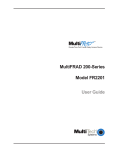
3.2
Front Panel
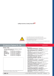
The MultiMux is equipped with a complete set of LED status indicators
and DIP switches located behind the front panel. The status indicators
show precisely what is occurring in the network at all times. By
periodically checking the indicators you can keep abreast of system
activity without tieing up a channel device or using the supervisory
console. The front panel indicators are divided into four main categories;
the Command Modem, External Composite Link device, Internal
Composite Link device and the system status indicators. The function of
each indicator by category is explained in section 3.3.
Command Modem
CD
RCV
XMT
OH
DTR
External Composite Link
CD
RCV
XMT
CTS
V.35
Channel Five
RCV
XMT
Channel one
RCV
XMT
Channel Six
RCV
XMT
Channel Two
RCV
XMT
Channel Seven
RCV
XMT
Channel Three
RCV
XMT
R
E
T
R
A
N
S
M
IT
Channel Eight
RCV
2
3
F
L
O
C
T
R
L
R
C
V
L
I
N
K
A
L
A
R
M
R
E
M
O
T
E
D
W
N
T
E
S
T
A
S
Y
N
C
M
O
D
E
L
I
N
K
INTERNAL LINK DEVICE
(Modems)
M
V
M
2
H
9
I
2
/
D
S
V
8
S
3
D
3
U
3
N
4
XMT
MultiTech
Systems
MultiMux
Statistical Multiplexer
Internal Composite Link
Channel Four
RCV
BUFFER
FULLNESS
LEVEL
1
XMT
ISDN
MMH2834
DSU
V29/V33
CD RCV XMT CTS 28.8
CD RCV XMT CTS 56
CD RCV XMT CTS
24.0
19.2
19.2
RTS
14.4
NS
OH
OOS
TR
TM
EC
DBUP
Figure 3-1. MultiMux Front Panel
34
Chapter 3 - Front & Rear Panel Descritpions
3.3
LED Indicators
Command Modem
Indicator
Description
CD
Indicates the local command modem has detected a
carrier signal from a remote modem.
RCV/XMT
Indicates that the command modem is on-line by
flashing with data activity between the two command
modems.
OH
Indicates that the dial-up line for the command
modem is off-hook.
DTR
Indicated that the command modem is ready to
communicate.
External Composite Link
CD
The Carrier Detect (CD) indicator is used when the
MultiMux MMH900 series is configured for an
external composite link device and a carrier signal is
detected.
RCV/XMT
The Transmit (XMT) and Receive (RCV) indicators
are used when the MultiMux MMH900 series is
configured for an external composite link device and
the network is on-line by flashing with data activity
between the two multiplexers.
CTS
The Clear To Send (CTS) indicator is used when the
MultiMux MMH900 series is configured for an
external composite link device and the composite
link device is ready to transmit data.
V.35
The V.35 indicator is used when the MultiMux
MMH900 series is configured for an external
composite link device which uses a V.35 interface.
The V.24/V.35 shunt has to be in the V.35 position
for this LED to light.
35
Chapter 3 - Front & Rear Panel Descritpions
Channel
Indicator
Description
Channel 1-8
The Channel Receive (RCV) and Transmit RCV/
XMT(XMT)indicators show the activity level on each
channel.MultiMux MMH904 uses Channel One
through Channel Four indicators. The MultiMux
MMH908 can connect up to eight async devices
which use Channel One through Channel Eight
indicators.
Internal Composite Link (MMH2834 Modem)
Indicator
Description
CD
The Carrier Detect (CD) indicator lights when the
MMH2834 composite link modem detects a carrier
signal from the remote link modem.
XMT
The Transmit (XMT) indicator flashes as data is
being transmitted by the MMH2834 modem to the
remote multiplexer.
RCV
The Receive (RCV) indicator flashes as data is
being received by the MMH2834 modem from the
remote multiplexer.
CTS
The Clear To Send (CTS) indicator lights when the
MMH2834 composite link modem is ready to
transmit data.
28.8, 24.0,
19.2, 14.4
These composite link speed indicators display
the receive baud rate of the internal composite link.
OH
The Off-Hook (OH) indicator lights when the
composite link is off-hook
TR
The Terminal Ready (TR) indicator lights when the
MMH2834 modem is permitted to answer an
incoming call. When the indicator goes off, the
connected composite link modem will disconnect.
EC
The Error Correction (EC) indicator is on solid when
the MMH2834 modem is in errorcorrection mode
and flashes on and off when compression is active.
DBUP
The Dial Back up (DBUP) indicator lights when the
MMH2834 modem is in dial back up mode.
36
Chapter 3 - Front & Rear Panel Descritpions
Internal Composite Link (DSU)
Indicator
Description
CD
The Carrier Detect (CD) indicator lights when the
composite link DSU detects a carrier signal from the
remote MultiMux.
XMT
The Transmit (XMT) indicator flashes as data is
being transmitted to the remote multiplexer on the
composite link.
RCV
The Receive (RCV) indicator flashes as data is
being received from the remote multiplexer on the
composite link.
CTS
The Clear To Send (CTS) indicator lights when the
composite link DSU is ready to transmit data.
56, 19.2
These composite link speed indicators display the
baud rate of the internal composite link.
RTS
The Request To Send (RTS) indicator lights when
the MultiMux has data it wants to transmit over the
composite link
NS
The No Signal (NS) indicator lights when no signal
at all is received from the DDS line or when the
signal is too weak for normal operation. This
indicator will also flash to indicate that errors have
been detected when using the Test Pattern
diagnostic feature.
OOS
The Out Of Service (OOS) indicator lights when an
out of service signal is detected from the teleco.
TM
The Test Mode (TM) indicator lights when the DSU
is placed in test mode.
Internal Composite Link (V29/V33 Modem)
Indicator
Description
CD
The Carrier Detect (CD) indicator lights when an
internal composite link 9600 or 14,400 bps modem
detects a carrier signal from the remote link modem.
XMT
The Transmit (XMT) indicator flashes as data is
being transmitted from an internal composite link
9600 or 14,400 bps modem to a remote multiplexer.
37
Chapter 3 - Front & Rear Panel Descritpions
RCV
The Receive (RCV) indicator flashes as data is
being received by an internal composite link 9600 or
14,400 bps modem from a remote multiplexer.
CTS
The Clear To Send (CTS) indicator lights when an
internal composite link 9600 or 14,400 modem is
ready to transmit data.
Internal Composite Link (ISDN)
Indicator
Description
CD
The Carrier Detect (CD) indicator lights when the
terminal adapter establishes a connection with the
remote unit.
XMT
The Transmit (XMT) indicator flashes as data is
being transmitted to a remote multiplexer.
RCV
The Receive (RCV) indine line, or modem problem).
Steady when buffer overflow conditions exist.
REMOTE DWN
The local mux cannot establish communications with
the remote mux.
TEST MODE
A device in the network is currently running a
maintenance diagnostic.
ASYNC LINK
The composite link is configured to transfer data in
asynchronous mode.
Internal Link Device (Modems)
Indicator
Description
56K DSU
This indicator lights when the internal link device is a
DSU.
V29/V33
This indicator lights when either an internal 9600 bps
(V.29) or 14,400 bps (V.33) modem is the composite
link device.
MMH2834
This indicator lights when the 28.8K bps internal
composite link modem is the composite link device.
ISDN
This indicator lights when the internal link device is
the ISDN terminal adapter.
38
Chapter 3 - Front & Rear Panel Descritpions
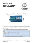
3.4
Back Panel
The cable connections for the MultiMux are made at the back panel.
Refer to Chapter 4 for cabling installation procedures. Refer to Appendix
C for cabling diagrams. The MultiMux back panel is shown in Figure 3-2.
I
COMMAND PORT
CHANNEL 8
CHANNEL 7
CHANNEL 6
CHANNEL 5
CHANNEL 4
CHANNEL 3
CHANNEL 2
CHANNEL 1
O
COMMAND
MODEM
DIAL-UP
COMPOSITE LINK
INTERNAL
DIAL UP
LEASED
MODEM
DIGITAL
DSU
EXTERNAL
RS232C/V.35
Figure 3-2. Back Panel
3.4.1
ON/OFF Switch
This switch provides AC power to the MultiMux when placed in the up
(ON) position and removes power when in the down position.
3.4.2
Power Connector
The power connector is a receptacle for a 3-prong grounded power cord.
3.4.3
COMMAND MODEM DIAL-UP Connector
This connector is used when the command modem is connected to a
separate dial-up line for remote access.
3.4.4
COMMAND PORT Connector
The command port connector is used to connect the supervisory console
to the MultiMux MMH900 series. The supervisory console can be either
an ASCII terminal or a pc with a serial port running communications
software. The command port connector has a DCE physical interface
with a DB25 female connector.
3.4.5
COMPOSITE LINK INTERNAL MODEM
DIAL-UP Connector
This composite link internal modem connector is used with an internal
composite link modem with a dial-up or dial back capability. This
connector provides an RJ11 connection.
39
Chapter 3 - Front & Rear Panel Descritpions
3.4.6
COMPOSITE LINK INTERNAL MODEM
LEASED Connector
This connector is used when the MultiMux MMH900 series is connected
to a lease line with an internal Multi-Tech 9600, 14.4K, or 28.8K bps
modem installed. The composite link internal modem leased connector
provides an RJ11 connection.
3.4.7
COMPOSITE LINK INTERNAL DIGITAL
DSU Connector
The composite link internal digital DSU connector is used when the
MultiMux MMH900 series is connected to a DDS or dedicated network
and an internal DSU is installed. This connector provides an RJ48
connection to the DDS or dedicated network.
3.4.8
COMPOSITE LINK EXTERNAL RS232C/
V.35 Connector
This connector is used when an external modem or DSU is connected to
the MultiMux MMH900 series. This connection can be either RS232C or
V.35. If the connection is V.35, then the shunt must be moved from the
RS232C position to the V.35 position. This connector is a DB25 female
connection.
3.4.9
CHANNEL 1 - CHANNEL 8 Connectors
Channel 1 through channel 8 connectors are used to connect the async
devices to the MultiMux MMH900 series. The MultiMux MMH904 has
four channel connectors. The MultiMux MMH908 has eight channel
connectors. These connectors provide the RS232C connection.
40
Chapter 3 - Front & Rear Panel Descritpions
3.5
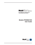
Switches/Jumper/Shunt
Switch settings can be changed by taking off the front panel. To change
the RKWL/144 jumper, V.24/V.35 shunt, V.29/V.33 shunt, or the 2834
shunt, the front panel and top cover need to be removed. The switches,
jumper and shunts are shown on the base in Figure 3-3.
V.35 Shunt
V.35
V.24 Shunt
V.24
V29/V33
2834
OTHER
1 2 3 4 5
RKWL14.4
6 7 8
1 2 3
4
8-Position Composite
DIP Switch Link Internal
Modem Jumper
4-Position
DIP Switch
V.29/V.33
Shunt
2834 Shunt
Power
Supply
Figure 3-3. Base
3.5.1
8-Position DIP Switch
The 8-position DIP switch is shown in Figure 3-3 and the function of
each position is as follows:
Switch position 1:
Closed
Initiate Downline Load Off
Open (UP) Initiate Downline Load On
(used for downline loading only)
Switch position 2:
Closed
External Link Device Selected
Open (UP) Internal Link Device Selected
Switch Position 3:
Closed
Four Channel Operation
Open (UP) Eight Channel Operation
Switch Position 4:
Closed
Disable Command Modem Remote
Access
Open (UP) Enable Command Modem Remote
Access (default)
Switch Position 5:
Not Used
41
Chapter 3 - Front & Rear Panel Descritpions
With an MMH904 Unit
C = Closed
Channel #
O = Open (Up)
1-4
5-8
9-12
13-16 17-20
21-24
25-28
29-32
Switch Position 6:
C
O
C
O
C
O
C
O
Switch Position 7:
C
C
O
O
C
C
O
O
Switch Position 8:
C
C
C
C
O
O
O
O
With an MMH908 Unit
Channel #
1-8
9-16
17-24
Switch Position 6:
C
O
C
O
Switch Position 7:
C
C
O
O
Switch Position 8:
C
C
C
C
3.5.2
25-32
4-Position DIP Switch
The four-position DIP switch determines the type of MultiMux at the other
end of the composite link. The function of the switch is as follows:
Remote Mux
Switch Position 1:
MM16/32
O
MM900
C
MMH16/32 MH900
O
C
Switch Position 2:
O
O
C
Switch Position 3:
Not Used
Switch Position 4:
Not Used
C
42
Chapter 3 - Front & Rear Panel Descritpions
3.5.3
144RKWL/OtherJumper
The 144 RKWL/OTHER jumper is positioned in the 144RKWL (Rockwell)
position when a 14,400 Rockwell internal composite link modem is used.
When any other internal composite link modem or DSU is used, this
jumper is in the OTHER position. The location of the jumper on the base
is shown in Figure 3-3 and the placement of the jumper is shown in
Figure 3-4.
OTHER/144RKWL
All other Internal
composite link
modems installed
OTHER/144RKWL
14400 Rockwell
Modem Install
(Optional Setting)
(Factory Default)
Figure 3-4. 144RKWL/Other Jumper
3.5.4
V.24/V.35 Shunt
An external composite link device with either an RS232C/V.24 or a V.35
interface can be connected to a MultiMux MMH900 series. When an
external composite link device with an RS232C/V.24 interface is
connected to the MultiMux, the V.24 shunt should be installed. When the
external composite link device has a V.35 interface, the V.35 shunt
should be installed. The V.24/V.35 shunt is shown in Figure 3-3. The
factory default for the shunt is in the V.24 position.
3.5.5
V.29/V.33 Shunt and 2834 Shunt
When an internal modem is being installed, the V.29/V.33 shunt or the
2834 shunt has to be in the correct position. This shunt is shown in
Figure 3-3. If a V.29 or V.33 modem is being installed, the shunt has to
be in the V.29/V.33 position. If a MMH2834 modem is being installed,
the shunt has to be in the 2834 position. If an internal ISDN terminal
adapter is installed, the shunt must be in the 2834 position.
43
Chapter 4- Installation
Chapter 4 - Installation
4.1
Introduction
This chapter explains how to unpack and install your MultiMux cabinet.
4.2
Safety Warnings
1. Never install telephone wiring during a lightning storm.
2. Never install telephone jacks in wet locations unless the jack is
specifically designed for wet locations.
3. Never touch uninsulated telephone wires or terminals unless the
telephone line has been disconnected at the network interface.
4. Use caution when installing or modifying telephone lines.
5. Avoid using a telephone (other than a cordless type) during an
electrical storm. There may be a remote risk of electrical shock from
lightning.
6. Do not use the telephone to report a gas leak in the vicinity of the
leak.
4.3
Unpacking
Unpack and check all the items in the MultiMux shipping list to ensure
that you have received the correct options and accessories.
MultiMux Components
A. MultiMux Cabinet
B. User Guide
C. Power cord
D. RJ11 phone cable (for internal modem)
E. RJ48 phone cable (for internal DSU)
F. Mux Converter Cable (for internal ISDN terminal adapter)
G. Composite Link cable ( for external modem)
Inspect the MultiMux cabinet for visible shipping damage. If damage is
observed, do not power-on the unit; refer to Chapter 8 of this Guide and
contact Multi-Tech's Tech Support for advice. If no damage is observed,
place the MultiMux cabinet in its final location.
Save the packing material for possible future use (e.g., return or
relocation).
45
Chapter 4 - Installation
4.4
Installation
Table 4-1. Installation Procedure
Composite Link Installation
1
MultiMux has an internal link modem and are connecting to a
dial-up service: Connect the RJ11 cable to the COMPOSITE LINK
INTERNAL MODEM DIAL-UP connector on the back panel of the
MultiMux and your phone line.
MultiMux has an internal link modem and are connecting to a
leased line service: Connect the RJ11 cable to the COMPOSITE
LINK INTERNAL MODEM LEASED connector on the back panel of
the MultiMux and your phone line.
MultiMux has an internal link DSU and are connecting to a DDS
or dedicated service: Connect the RJ11 cable to the COMPOSITE
LINK INTERNAL DIGITAL connector on the back panel of the
MultiMux and your phone line.
MultiMux has an internal link ISDN terminal adapter: Connect the
Mux Converter cable supplied with the unit to the COMPOSITE LINK
INTERNAL DIGITALconnector on the back panel of the MultiMux
and your phone line.
MultiMux is being connected to an external modem with an
RS232C interface: Connect the composite link cable shipped with
your MultiMux to the COMPOSITE LINK EXTERNAL RS232C/V.35
connector on the back panel and to the RS232 connector on the
external modem.
MultiMux is being connected to an external modem with a V.35
interface: Connect a V.35 interface adapter cable Multi-Tech
(#90056210) to the COMPOSITE LINK EXTERNAL RS232C/V.35
connector on the back panel and to the V.35 connector on the
external modem.
I
COMMAND PORT
CHANNEL 8
CHANNEL 7
CHANNEL 6
CHANNEL 5
CHANNEL 4
CHANNEL 3
CHANNEL 2
CHANNEL 1
O
COMMAND
MODEM
DIAL-UP
COMPOSITE LINK
EXTERNAL
INTERNAL
DIAL UP
LEASED
MODEM
DIGITAL
DSU
RS232C/V.35
COMPOSITE LINK
INTERNAL
DIAL UP
LEASED
MODEM
DIGITAL
DSU
RS232C/V.35
Figure 4-1. Composite Link Cabling
46
Chapter 4 - Installation
External modem with V.35 interface is being connected: Remove
the top cover and move the V.24/V.35 shunt from the V.24 position to
the V.35 position. Replace the top cover.
V.35 Shunt
V.35
V.24 Shunt
V.24
V29/V33
MultiTech
Systems
OTHER
1
2
2
3
4
5
6
7
8
MMH956
2834
V.29/V.33
Shunt
RKWL14.4
1
2
3
4
2834 Shunt
Figure 4-2. Shunts
Connect the AC power cord shipped with your MultiMux to the AC
power connector on the back panel and to the AC outlet.
3
Press the power ON/OFF switch on the back panel of the MultiMux
to apply power.
4
If the internal composite link modem is V.34/28800 bps, verify that
the INTERNAL LINK DEVICE Modem MMH2834 LED on the front
panel is ON.
If your MultiMux is configured for an external composite link sync
modem, verify that the External Composite Link XMT and CTS LEDs
are ON. If the external composite link modem has a V.35 interface,
verify that the V.35 LED is also ON.
If a DSU is installed in your MultiMux, verify that the 56K DSU LED
is ON.
47
Chapter 4 - Installation
Supervisory Console
5
If you are connecting a supervisory console to the MultiMux, connect
a terminal or PC to the COMMAND PORT connector via an
appropriate RS232C cable. The PC needs to be running
communications software.
Note: Any cables connected to the computer should be shielded to
reduce interference.
I
COMMAND PORT
CHANNEL 8
CHANNEL 7
CHANNEL 6
CHANNEL 5
CHANNEL 4
CHANNEL 3
CHANNEL 2
CHANNEL 1
O
COMPOSITE LINK
COMMAND
MODEM
EXTERNAL
INTERNAL
DIAL UP
LEASED
MODEM
DIAL-UP
DIGITAL
DSU
RS232C/V.35
COMMAND PORT
6
Figure 4-3. Supervisory Console Cabling
Apply power to the supervisory console and enter AT and then hit
Return. If you get an OK message back, you are communicating
with the Command Port..
Command Modem
7
To connect the built-in command modem to a standard phone line,
connect the RJ11 cable to the COMMAND MODEM DIAL-UP
connector on the back panel of the MultiMux and the phone jack.
I
COMMAND PORT
CHANNEL 8
CHANNEL 7
CHANNEL 6
CHANNEL 5
CHANNEL 4
CHANNEL 3
CHANNEL 2
CHANNEL 1
O
COMMAND
MODEM
DIAL-UP
COMPOSITE LINK
INTERNAL
DIAL UP
LEASED
MODEM
DIGITAL
DSU
EXTERNAL
RS232C/V.35
COMMAND
MODEM
DIAL-UP
Figure 4-4. Command Modem Cabling
48
Chapter 4 - Installation
Channel
8
Route and connect your channel devices to the MultiMux back panel
CHANNEL 1 - CHANNEL 4 on a MultiMux MMH904 or CHANNEL 1
- CHANNEL 8 on aMultiMux MMH908 connectors using RS232
cables. Do this at both of your sites, so that channel 1 at one site
communicates with channel 1 at the other site, and so on.
Note: Any cables connected to the computer should be shielded to
reduce interference.
Follow channel device guidelines regarding RS232 cable lengths
and make sure that the pin assignment in Appendix C of this manual
are followed.
I
COMMAND PORT
CHANNEL 8
CHANNEL 7
CHANNEL 6
CHANNEL 5
CHANNEL 4
CHANNEL 3
CHANNEL 2
CHANNEL 1
O
COMPOSITE LINK
COMMAND
MODEM
DIAL-UP
EXTERNAL
INTERNAL
DIAL UP
LEASED
MODEM
DIGITAL
DSU
RS232C/V.35
Channels
9
Figure 4-5. Channel Cabling
Execute the parameter display command to display the current
channel parameter status for your local MultiMux by entering the
following:
ATL (press Return)
The following will be displayed on your supervisory console for a
MultiMux MMH904:
Local Channel Parameter
CHN
01
02
03
SPD WORD
19200
8
19200
8
19200
8
STP
BIT
1
1
1
PARITY
NONE
NONE
NONE
FLOW
CONTROL
XON/XOFF
XON/XOFF
XON/XOFF
ENQ/
ACK
OFF
OFF
OFF
ECHO
OFF
OFF
OFF
PACE
OFF
OFF
OFF
PASS
EIA
OFF
OFF
OFF
PASS
XON
OFF
OFF
OFF
04
19200
1
NONE
XON/XOFF
OFF
OFF
OFF
OFF
OFF
8
10 Based on the listed conditions for each channel, reconfigure the
parameters to match your actual channel requirements by entering
commands as described in Chapter 4.
As you change operational parameters, they will not actually be
incorporated into your running system until you execute a Store New
Parameters (&W).
49
Chapter 4 - Installation
As you change operational parameters, they will not actually be
incorporated into your running system until you execute a Store New
Parameters (&W) command.
50
Chapter 5 - Commands
Chapter 4 - Installation
5.1
Introduction
This chapter presents a command summary followed by a detailed
description of each command used in the MultiMux. The structure of the
commands is that they all begin with the prefix AT. Each command line
may contain any number of commands in a string (no spaces) up to a
limit of 40 characters. Most commands include a value and are part of
the 40 character total. Hitting Return executes a command line but does
not incorporate it into the operation of your MultiMux. You must execute
a Store New Parameters command to implement your changes into your
mux network.
An example of a command line which changes the parameters of the
channel device connected to channel 1. The following command
changes the baud rate to 4800 bps, parity to odd, CTS flow control and
turns echo off.
ATC1B4800P2F1E0
Table 5-1 presents a summary of all the commands used in the
MultiMux. The commands are divided into a number of general
categories according to their functionality within the MultiMux. This
functional division is carried on into the detailed description of each
command.
The access commands for the command modem are described in this
chapter. The general AT commands for the command modem are
described in Appendix D.
Table 5-1. Command Summary
TYPE
COMMAND
DESCRIPTION
General
H
H1
H2
H3
H4
H5
H6
General Help
Channel Parameter Help
DIP-Switch Configuration Help
Async/Sync Composite Link Format Help
Additional Composite Link Help
Miscellaneous Help
Internal V.29/V.33 Composite Link Modem
Configuration Help
Internal DSU Help
Reset
Store New Parameters to Memory
H7
Z
&W
52
Chapter 5 - Commands
Table 5-1. Command Summary (cont.)
TYPE
COMMAND
DESCRIPTION
Channel
B0
Channel Off Command
Parameter Bxxx
Baud Rate Select
C0
Universal Channel Parameters Command
C1-C8
Channel Select for Parameter Change
DCx
Destination Channel
DNx
Destination Node Number
E0
Echo Off
E1
Echo On
F0
Flow Control Off
F1
CTS (RS232C) Flow Control
F2
Xon/Xoff Flow Control
F3
Enq/Ack On
F4
EnqAck Off
F5
Pacing On
F6
Pacing Off
F7
Pass EIA (RS232C) Signals On
F8
Pass EIA (RS232C) Signals Off
F9
Xon Pass Thru On
F10
Xon Pass Thru Off
F11
Inverter DTR On
F12
Inverter DTR Off
F13
Xoff/First Character Pacing
F14
Xoff/Xon Character Pacing
F15
XPC Flow Control On
F16
XPC Flow Control Off
I0-2
Identification Commands
L,L0
List all Channel Parameters
L1-L8
List individual Channel
P0
Parity None
P1
Parity Odd
P2
Parity Even
53
Chapter 5 - Commands
Table 5-1. Command Summary (cont.)
TYPE
COMMAND
DESCRIPTION
Channel
R0-3
Response Time Priority
Parameter SB1
Stop Bit 1
SB1.5
Stop Bit 1.5
SB2
Stop Bit 2
SN
Local Source Node Number
WL5
Word Length 5
WL6
Word Length 6
WL7
Word Length 7
WL8
Word Length 8
&F
Load Factory Defaults
&SL
Select Local Parameter
&SR
Select Downline Parameters
#S1-8
Channel Status Reports
Composite Link
#C
Clear Composite Statistics
#CLA
Composite Link Access
$F
Load Factory Defaults for DSU and ISCC
#FT
Flush Timer Value
$L
List Composite Link Configuration
#L
List Composite Link Settings
#RB
Set Auto reporting Baud Rate
#RT
Set Auto Reporting Time Interval
#S
Status Reporting
#S9
Status of Front Panel LEDs
Composite Link Format
#EOFR
Receive End Of Frame Character
#EOFT
Transmit End Of Frame Character
$MUXCL
Mux Clock
$MUXSP
Mux Speed
#SYNC
Synchronous Composite Link
#ASYNC
Asynchronous Composite Link
54
Chapter 5 - Commands
Table 5-1. Command Summary (cont.)
TYPE
COMMAND
DESCRIPTION
Internal 9600/14.4K Composite Link Modem
$MC
Modem Configuration Select
$EP
Echo Protect Tone
$LA
Link Amp Set
$LD
Link Delay Set
$CQ
Cable Equalization
$RL
Receive Level
$TL
Transmit Level
$T
T/2 Adaptive Equalizer
$W
Write Configurations to modem
Internal MMH2834 Modem Configuration
$M(ASYNC/SYNC)
MMH2834 Sync or Async Mode
$M(DIAL/LEASED)
Dail up or leased line
$MWIRE(2/4)
2 or 4 wire leased line
$MTL(0/10)
Transmit Level 0 or -10 db
$M (ANSWER/ORIGINATE)
Lease Line Answer or
Originate Mode
$MCOMMAND
Enables or disables Command
Mode
$MTR
Data Transmission Rate
Internal DSU
Test
$DSUCL
Selects Clocking for Internal DSU
$DSUSP
Selects Speed of Internal DSU
&T1-3
Memory Tests
&T4
Local Loop
&T5
Digital Loop
&T6
Remote Analog Loop
&T7
Switch and LEDs
&T8
Memory Test
&T9
Watch Dog Timer Test
&T10
Internal Modem Memory Test
55
Chapter 5 - Commands
Table 5-1. Command Summary (cont.)
TYPE
COMMAND
DESCRIPTION
#MA
Command Modem Select
#RA
Remote Command Modem
Access
Command
Modem
56
Chapter 5 - Commands
5.2
Command Description
The following command descriptions explain the effect that executing
each command has on your MultiMux network. Refer to Chapter 6 for
instructions on how to execute the commands.
5.2.1
Z
General Commands
Reset
The Reset command will set the operating
parameters of the MultiMux to its most recently
stored values. Executing the Reset command
performs the same function in the logic as turning
power off and then on to the unit.
&W
Store New Parameters
The Store New Parameters command causes the
MultiMux to store new parameters. Prior to
executing the &W command, any changes to
MultiMux parameters are temporary and do not
affect the unit’s operation until you execute the &W
command followed by a reset Z command. The &W
command stores the parameters in nonvolatile
memory and will take affect upon reset or powering
the MultiMux off and on.
H, H1-H8
Help
The Help commands are designed to give you short
explanations on how to use MultiMux commands.
They will be useful if your manual is not handy,
although the explanations are quite short in
comparison to those in the manual. When a Help
command is executed in conjunction with some
other command, the resulting display will explain
options and information for that command. The
General Help command provides information on the
other MultiMux Help commands.
57
Chapter 5 - Commands
The H command menu is as follows:
General Help
- Each command line must begin with the prefix AT.
- Each command line may contain any number of commands up to
40
characters total.
- Most command letters must be followed by a value.
- For help on specific commands, enter "ATH" followed by one of the
command letters.
ATH1 for channel parameter commands.
ATH2 to view the DIP switch configurations.
ATH3 for async and sync composite link format commands.
ATH4 for additional composite link commands.
ATH5 for miscellaneous commands.
ATH6 for internal V.29/V.33 composite link modem commands.
ATH7 for internal DSU commands.
ATH8 for internal MMH2834 modem commands
For additional help menus, enter one of the following ATH codes to
obtain the desired information:
ATH or ATH0 for General Help.
58
Chapter 5 - Commands
The H1 Menu is as follows:
CHANNEL PARAMETER COMMANDS
B
BAUD RATE SELECTION
P
PARITY SELECTION
C
CHANNEL SELECTION
R
RESPONSE TIME PRIORITY
DC
DEST. CHANNEL SELECTION
SB
STOP BIT SELECTION
DN
DEST. NODE SELECTION
SN
LOCAL SOURCE NODE NUMBER
E
LOCAL ECHO
#S
CHANNEL STATISTICS
F
FLOW CONTROL
&SL
SELECT LOCAL PARAMETERS
&F
READ IN FACTORY DEFAULTS
&SR
SELECT DOWNLINE LOAD PARAMETERS
L
LIST PARAMETERS
WL
WORD LENGTH SELECTION
The following example will select CHANNEL 1 and set its baud rate to
2400 and the WORD LENGTH to 8 bits:
ATC1B2400WL8 <ENTER>
For HELP on a specific command, enter “ATH” followed by a command
letter.
59
Chapter 5 - Commands
The H2 Menu is as follows:
MULTIMUX Eight Position DIP-Switch Definitions and Settings
Switch 1
Initiate
Dwn
Line
Load
Switch 2
Link
Device
Switch 3
8/4
Channel
UP = ON
DN = OFF
INTERNAL
EXTERNAL
8 CHAN
4 CHAN
CURRENT SETTINGS:
DN
1-4
SW#6
DN
SW#7
DN
SW#8
DN
1-8
SW#6
DN
SW#7
DN
SW#8
DN
DN
5-8
UP
DN
DN
9 - 16
UP
DN
DN
Switch 4
Remote
Access
Switch 5
Not
Used
SEE TABLE BELOW
ENABLED
DISABLED
DN
9 - 12
DN
UP
DN
17 - 24
DN
UP
DN
Switch 6, Switch 7, Switch 8
Channel Group Select
When MM16 or MMH16
Series is selected
DN
13 - 16
UP
UP
DN
25 - 32
UP
UP
DN
DN
17 - 20
DN
DN
UP
DN
21 - 24
UP
DN
UP
DN
25 - 28
DN
UP
UP
DN
29 - 32
UP
UP
UP
Note: Hit any key to display four position DIP Switch or control C to
abort MultiMux four position DIP Switch definitions and configurations.
Switch 1
Switch 2
Mux Mode Mux Mode
Select
Select
UP =
DN =
Switch 3
Not
Used
Switch 4
Not
Used
DN
DN
16/32 MM
900 MMH/MMV
Current Setting:
DN
DN
60
Chapter 5 - Commands
The H3 Mend is as follows:
COMPOSITE LINK FORMAT COMMANDS
#EOFR - SELECTS RECEIVE END OF FRAME CHARACTER FOR
ASYNC LINK.
#EOFT - SELECTS TRANSMIT END OF FRAME CHARACTER FOR
ASYNC LINK.
$MUXCL - SELECTS INT/EXT CLOCKING OF MUX COMPOSITE
LINK.
$MUXSP - SELECTS SPEED OF MUX COMPOSITE LINK WHEN MUX
CLOCKING IS INTERNAL OR ASYNC LINK IS SELECTED.
#SYNC - SELECTS SYNC COMPOSITE LINK
#ASYNC - SELECTS ASYNC COMPOSITE LINK
For HELP on a specific command, enter "ATH" followed by the command
letter:
EXAMPLE: ATH$MUXCL "ENTER"
The H4 Menu is as follows:
COMPOSITE LINK COMMANDS
#C
CLEAR COMPOSITE STATISTICS
#CLA COMPOSITE LINK ACCESS
#DTR TOGGLE DTR ON THE COMPOSITE LINK
$F
LOAD FACTORY DEFAULTS FOR DSU AND ISCC
#FT
FLUSH TIMER VALUE
$L
LIST COMPOSITE LINK CONFIGURATION
#L
LIST COMPOSITE LINK SETTINGS
R
RESPONSE TIME PRIORITY
#RB
SET AUTO REPORTING BAUD RATE
#RT
SET AUTO REPORTING TIME INTERVAL
61
Chapter 5 - Commands
#S
STATUS REPORTING
#S9
STATUS OF FRONT PANEL LEDS
For HELP on a specific command, enter “ATH” followed by a command
letter.
The H5 Menu is as follows:
MISCELLANEOUS COMMANDS
I
ID CODE
#MA
MODEM ACCESS FOR COMMAND MODEM
#RA
REMOTE ACCESS FOR COMMAND MODEM
&T
TEST MODES
&W
SAVE PARAMETERS "WRITE TO MEMORY"
Z
RESET MULTIMUX
For HELP on a specific command, enter “ATH” followed by a command
letter.
The H6 Menu is as follows:
Commands to configure the MultiMux Internal V29/V33 modem
$CQ
CABLE EQUALIZER
$EP
ECHO PROTECTOR CONTROL
$F
READ IN FACTORY DEFAULTS FOR MODEM
$L
LIST INTERNAL MODEM PARAMETERS
$LA
LINK AMPLITUDE EQUALIZER
$LD
LINK DELAY EQUALIZER
$MC
MODEM SPEED CONFIGURATION
$RL
MODEM RECEIVE LEVEL
$TL
MODEM TRANSMIT LEVEL
$T
(T/2) ADAPTIVE EQUALIZER
$W
WRITE CONFIGURATIONS TO MODEM #DOES NOT
SAVE#
62
Chapter 5 - Commands
The H7 Menu is as follws:
INTERNAL DSU COMMANDS
#DSUCL
SELECTS CLOCKING FOR INTERNAL DSU.
#DSUSP
SELECTS SPEED FOR INTERNAL DSU.
For HELP on a specific command, enter “ATH” followed by a command
letter.
The H8 Menu is as follows:
INTERNAL MMH2834 COMMANDS
$M(ASYNC/SYNC)
SYNC OR ASYNC.
$M(DIAL/LEASED)
DIAL UP OR LEASE LINE
$MWIRE(2/4)
2 OR 4 WIRE LEASE LINE
$MMTL(0/1)
TRANSMIT LEVEL 1 OR -10DB
$M(ANSWER/ORIGINATE)
ANSWER OR ORIGINATE
MODE FOR LEASED LINE
$MCOMMAND(0/1)
ENABLE OR DISABLE
COMMAND MODE
$MTR(28800/91200
/1440/9600)
DATA TRANSMISSION RATE
For HELP on a specific command, enter “ATH” followed by a command
letter.
63
Chapter 5 - Commands
5.2.2
Channel Parameter Commands
Command
Description
BO
Channel Off Command
The channel off command turns the selected
channel off. This command turns off a particular
channel or all channels depending on the
command. This allows the more efficient use of the
dynamically allocated buffers and allows the
multiplexer to skip the scanning of unused channels.
Bxxxx
Baud Rate Select
The Bxxxxx command selects the bps rate on the
indicated channel. The channel bps rate is from 300
bps to 38.4K bps.
CO
Universal Channel Parameters
The Universal Channel Parameters command
incorporates the commands that follow it (all prior to
a Carriage Return) into all the channels. This allows
you to change such conditions as baud rate, word
length, parity and flow control on all channels by
executing a single command.
C1-C8
Channel Select
The Channel Select command selects an individual
channel on which subsequent commands can
operate. The Channel Select command must
precede any of the other commands but remains in
effect until changed. This is so that a string
ofcommands can be entered without preceding each
one with a Cx command.
DCxx
Destination Channel Number
This command is not necessary when a MultiMux
900 Series is connected to another MultiMux 900
series. The Destination Channel Number command
DCxx is necessary when an MMH904/MMH908 is
connected to a MultiMux16 or MultiMux 32 model.
The DCxx command specifies the destination
channel to which the source channel is
communicating. A specific channel can only
64
Chapter 5 - Commands
communicate with one other channel. On multinode
networks, this command must be entered at both
channel locations specifying each other as
destinations (channels can pass through two nodes
to get to its destination). On point-to-point networks,
this parameter can be downline loaded.
DNxx
Destination Node Number
This command is not necessary when a MultiMux
900 Series is connected to another MultiMux 900
Series. The destinatnion Node Number DNxx is
necessary when MMH904/MMH908 is connected to
a MultiMux16 or MultiMux32 model.
The DNxx command specifies the node number of
the destination node for output operations from a
local node. It specifies the destination node of the
channels to which the local source channels will
connect. For example, if some node in your network
is assigned 01 as its number (a node where its SN
command was SN01), you can communicate with
the 01 location channels by executing a DN01
command. At that point, your local channels will
communicate with those at node 01. The specific
channel connections will be determined by the
“virtual” channel number you have set up with the 8position DlP-Switch SW6, SW7, and SW8.
EO-1
Echo Command
The E0-E1 commands turn on and off the echoplex
feature of the MultiMux. When the echo condition is
on, the data entered on the channel keyboard is
returned to the channel display. The purpose of this
is so that in interactive operations an operator will
not experience undue delays in seeing data appear
on the monitor. When the echo condition is off, the
keyboard data is not returned to the monitor. E1
turns on echoplex and E0 turns it off.
F0-F2
Flow Control Operations
Flow Control is the means by which data flow is
controlled from the channel devices into the
MultiMux. Flow Control is necessary when the data
handling capacity of an individual channel cannot
65
Chapter 5 - Commands
keep up with the volume of data sent to it. There are
two types of flow control available on the MultiMux.
The software based Xon/Xoff and hardware based
Clear to Send (CTS). F0 turns flow control off, F1
selects CTS flow control, and F2 selects Xon/Xoff
flow control. The way channel devices control the
data flow to them from the MultiMux is called Pacing
(see Pacing command).The combination of Flow
Control for regulating data from individual channel
devices and pacing for regulating data to individual
channel devices is how data transfers are regulated
so that no data is lost.
MUX INITIATED
FLOW CONTROL
CHANNEL DEVICE
INITIATED PACING
DATA
DATA
Channel
Device
Mux
Flow control stops the
input of data to the mux
F3-F4
Mux
Channel
Device
Pacing stops the output
of data from the mux
ENQ/ACK Flow Control
These two commands control the selection of a
special flow control system used in Hewlett Packard
computer systems. It is sometimes referred to as
Enquire/Acknowledge flow control because it’s
based on the computer sending an inquiry (ENQ)
and then expecting an acknowledgment (ACK). F3
turns on this feature and F4 turns off the feature.
F5-F6
Pacing Control
The Pacing Control command (F5-on, F6-off) is the
means used to control data flow to channel devices.
Pacing is necessary when devices operating on a
mux channel require more than one character time
to process the data, the pacing commands initiate
control so that data is not lost in the transfer
process. The MultiMux is shipped with pacing off
and it will have to be turned On if your channel
device cannot accommodate the data volume.The
pacing method used is determined by the type of
flow control.
F7-F8
Pass EIA Signals
The Pass EIA Signal commands (F7-on, F8-off) are
the commands that enable or disable individual
66
Chapter 5 - Commands
channels to receive EIA control signals through the
MultiMux. Since in normal interactive operations, the
existence of a multiplexer should be transparent to
individual users, the Pass EIA Signals command will
allow terminals to operate as if they were connected
directly to a communications line and not through a
multiplexer. This is done by allowing selected pins
(signals) on one mux to be passed through to
selected pins (signals) on a second remote mux.
The following diagram shows how the Pass EIA
Signals command routes the selected signals:
MultiMux
(A)
IN 4
IN 20
IN 25
OUT 8
OUT 6
OUT 22
F9-F10
MultiMux
(B)
Composite Link
Facility
(Effect of the
PASS EIA
Signal
F7
Command)
8 OUT
6 OUT
22 OUT
4 IN
20 IN
25 IN
PassXon/Xoff
The Pass Xon/Xoff commands, (F9-enable, F10disable), are active only if Xon/Xoff flow control is
active. Also called the “Pass Through” commands,
they enable or disable the MultiMux from passing
through Xon/Xoff flow control signals. In the Enable
mode, the MultiMux will obey the Xon/Xoff
commands and pass them on to the channel device.
When this command is enabled, a message "TO
PREVENT DATA LOSS TO A PRINTER OROTHER
PERIPERAL WE RECOMMEND USING FLOW
CONTROL AND PACING, NOT PASS XON," is sent
to the channel device. In the Disable mode, the
MultiMux will obey the Xon/Xoff commands and not
send them to the channel device. The default
condition is for Xon/Xoff Pass Through to be
disabled and it normally should remain disabled.
However, in situations such as a slow data rate of a
channel device, disabling the passing of Xon/Xoff
signals may improve throughput by utilizing buffers
in the mux.
67
Chapter 5 - Commands
F-11-F12
Inverted DTR
The Inverted DTR Commands (F11 and F12) work
in conjunction with Pacing Control and change the
way the MultiMux reacts tothe DTR signal. With
Xon/Xoff Flow Control and Pacing, you will end up
with Xon/Xoff Pacing, and with CTS Flow Control
plus Pacing, data flow will be controlled by the
presence of the DTR (pin 20) signal on the RS232
interface. F11 turns on Inverted DTR so that a high
signal stops data flow and a low starts data flow.
F12 turns off Inverted DTR so that it acts normal
(high on and low off). If Flow Control is off, Pacing
cannot be turned on. If Pacing is off, inverted DTR
cannot be turned on.
F13-F14
Xoff/First Char.
F13 is a special pacing command that is called X/off
First Character pacing. Selecting F13 causes the
MultiMux to stop data flow to the channel device
upon receipt of a Xoff Character. The next character
from the channel device will start data (it does not
have to be an Xon Character). F14 will turn off this
feature.
F15-F16
XPC
XPC is a special flow control that is used with the
Xon/Xoff flow control. This flow control command
changes the characters for stopping and starting
data to 65H and 67H. F15 enables XPC flow
control. F16 disables XPC flow control.
I0-1
Identification Commands
The Identification commands identify the type of
MultiMux. This information is valuable when
communicating with Multi-Tech's Technical Support
personnel about your unit or its performance. The l0
command identifies the product. The I1 command
indicates the unit’s firmware type.
L-L0, L1-L8
List Channel Parameters
The List Channel Parameters command causes the
MultiMux to display the condition of the parameters
for each channel on the system’s supervisory
68
Chapter 5 - Commands
console as shown in the following example. To
display the parameters for an individual channel, say
channel three, you would enter ATL3 and hit your
Return key.To display the parameters for all of the
channels, enter ATL0 and then hit your Return key.
Local Channel Parameter
CHN
01
02
03
SPD WORD
19200
8
19200
8
19200
8
STP
BIT
1
1
1
PARITY
NONE
NONE
NONE
FLOW
CONTROL
XON/XOFF
XON/XOFF
XON/XOFF
ENQ/
ACK
OFF
OFF
OFF
ECHO
OFF
OFF
OFF
PACE
OFF
OFF
OFF
PASS
EIA
OFF
OFF
OFF
PASS
XON
OFF
OFF
OFF
04
19200
1
NONE
XON/XOFF
OFF
OFF
OFF
OFF
OFF
PO-2
8
Parity Select
The Parity Select commands set the parity of the
MultiMux operations. Under normal operations
(default conditions) parity is off and the word length
is set at eight bits. Since the MultiMux is intended to
be transparent to channel device operation, this
combination will pass parity information to the
channel devices.The P0 command turns parity off,
P1 sets odd parity and P2 setsit at even.
R
Response Time Priority
The Response Time Priority command determines
how long the mux will wait to send data from
channel devices relative to each other. An R0 setting
is the shortest and R3 the longest. The function of
the Response Time Priority commands is to ensure
that channel operations which require heavy data
transfers, such as program transmissions or print
operations, do not use too much of the buffer and
reduce the throughput of the other channels to
unsatisfactory levels. In such cases, the
interactiveuser who needs immediate responses
would experience unreasonable delays. The
Response Time Priority numbers 0,1, 2, and 3
establish the relative time each channel must wait
for data. The lower the number the shorter the wait.
An R3 number is the most efficient for throughput
(allows more data to be assembled before sending a
block) so if your mux is used mainly for printing an
R3 setting is the best. R0 provides the fastest
response time so that your interactive users should
69
Chapter 5 - Commands
use an R0 setting. If the mux is configured mainly
for interactive users, R0 is the best setting.
SB1,SB1.5, SB2
Stop Bits
The Stop Bit commands set the number of stop bits
used in asynchronous characters. The default
condition is one stop bit SB1. An SB1 command
sets one, an SB1.5 command sets 1.5, and an SB2
command sets two stop bits.
SN
Source Node Number
This command is not necessary when a MultiMux
900 Series is connected to another MultiMux 900
Series. SN is necessary when an MMH904/
MMH908 is connected to a MultiMux 16 or
MultiMux32 model. The SN command specifies the
node number of the local node. This number is
determined by you and can be any decimal number
up to 255. It should be assigned when you are
designing your network and needs to be unique to
any other node in your network. Remember that the
node number selected will be used by other nodes
(using a DNxxx command) when accessing the
node. For example, if you assign124 as the SN of a
local node (SN124 command), accessing thatnode
from another node requires 124 in the other
nodesDestination Node's number command
(DN124).
WL5-8
Word Length Select
The Word Length Select commands set the word
length for asynchronous communications. The
selections available are 5, 6, 7, and 8 bits which
correspond to WL5 through WL8.
70
Chapter 5 - Commands
&F
Load Factory Parameters
The factory default command resets the MultiMux
parameters to their original factory settings. They
are as follows:
&SL
Channel Speed:
19200 bps
Word Length:
8 bits
Stop Bits:
One
Parity:
None
Flow Control:
XON/XOFF
Enq/Ack Control:
Off
Echo:
Off
Pacing:
Off
Pass EIA:
Off
Pass Xon/Xoff:
Off
Response Time Priority:
3
Select Local Parameters
The Select Local Parameters command lists the
local channel parameters and enables you to update
them. After the execution of this command, all other
commands will act on the local parameter set. An
&W command stores the parameters. When power
is turned on, the local parameter mode is in effect.
&SR
Select Downline Load Parameters
The Select Downline Load Parameters command
lists the remote mux channel parameters and
enables you to update them. After execution of this
command, all other commands will act on the
downline parameter set. To send a new set of
parameters to the remote MultiMux unit, 1) the
Downline Load switch (8-position DIP switch SW1)
must be set properly , 2) then executing an ATZ or
powering off your unit sends the parameters to the
remote mux. Execute an &W to store the
parameters.
71
Chapter 5 - Commands
#S1-S8
Channel Status
The Channel Status command displays the
individual channel percentage activity levels and
signal pin status. The status message is displayed in
the following format.
STATISTICS FOR CHANNEL NUMBER XX
RECEIVE FLOW CONTROL TIME : 00 HRS 00MIN 00SEC
BUFFER UTILITZATION
: 00%
EIA STATUS:
FLOW CONTROL REQUEST SENT?: NO
PACING REQUEST RECEIVED?: NO
PIN #: 4/RTS 5/CTS
6/DSR
TYPE : INPUT OUTPUT OUTPUT
STATUS : LO HI
HI
8/DCD
20/DTR 22/RI
25/OOS
OUTPUT INPUT OUTPUT INPUT
HI
LO
LO
LO
72
Chapter 5 - Commands
5.2.3
Composite Link Commands
The Composite Link commands perform the function of a system
monitor. In addition to displaying the information available on the
MultiMux’s LED display, they also provide additional network statistical
information. The purpose of the commands are to allow network
monitoring via the supervisory port as an alternative to viewing the LED
indicators. The various status commands and their functions are detailed
below:
Command
Description
#C
Clear Composite Statistics
The Clear Composite Statistics command clears the
composite statistics record without resetting the
entire MultiMux unit.
$F
Load Modem Default
The Load Modem Default command returns the
status of the internal composite link modem or
DSU to its original status as shipped from the
factory. The default conditions for a 9600 bps
modem are as follows:
#FT
Speed:
9600
RCV Level:
-43 dbm
TX Level:
0 dbm
Cable Equalization:
0.0km
Link Amp:
off
Link Delay:
off
T/2 Equalization:
T2
Echo Protect:
off
Test Mode:
off
Flush Timer Value
This command is necessary when the mux is used
with Alpha-Microcomputer and Wyse Terminals. The
command allows for the proper use of the function
keys as indicated on the keys. The #FT0 command
clears the function and sets the flush time value to
73
Chapter 5 - Commands
10 msec and #FT1 sets the flush time value to 20
msec. The default is #FT0.
$L
List Composite Link Configuration
The List Composite Link Configuration command
causes the MultiMux to display its internal composite
link parameters on the supervisory console. Five
different parameter displays can be shown
depending on the internal composite link device. The
first example shows the default parameters for a
9600 bps internal modem. Example two shows the
14.4K bps internal modem. The third example shows
two sets of parameters for an internal the MMH2834
internal modem. The fourth example shows the
MultiMux configured for a 19.2K bps external
composite link modem (8-position DIP switch SW2
in the down position). Example five shows the
MultiMux configured for an internal composite link
DSU.
MODEM
CONFIGURE
V29/9600
TXMIT RECV CABLE LINK LINK T/2 ECHO TEST
LEVEL LEVEL EQU AMP DELAY EQU PROT MODE
-0DB
MODEM
CONFIGURE
V33/14400
-43DB
0.0KM
OFF
OFF
T2
OFF
OFF
TXMIT RECV CABLE LINK LINK T/2 ECHO TEST
LEVEL LEVEL EQU AMP DELAY EQU PROT MODE
-0DB
-43DB
0.0KM
OFF
OFF
T2
OFF
OFF
LINK
LINK
MUX
MUX
BACK TO EOF XMT
EOF RCV
LOOP
DEVICE FORMAT SPEED CLOCKING BACK
CHARACTER CHARACTER BACK
MMH2834 SYNC
57600
EXTERNAL OFF
FF
FF
OFF
TRANSMISSION SYNC
DIAL
2 OR 4 ANSWER TRANSMIT
RATE
ASYNC LEASED
WIRE ORIGINATE
LEVEL
28800 SYNC
LEASED 4 WIRE ANSWER
0 DB
ON
COMMAND
MODE
LINK
LINK
MUX
MUX
BACK TO EOF XMT
EOF RCV
LOOP
DEVICE FORMAT SPEED CLOCKING BACK
CHARACTER CHARACTER BACK
External
SYNC
19200
EXTERNAL OFF
FF
FF
OFF
LINK
LINK
DSU
DSU
EOF XMT
EOF RCV
LOOP
DEVICE FORMAT SPEED CLOCKING CHARACTER CHARACTER BACK
DSU
#L
SYNC
56000
DSU
N/A
N/A
OFF
List Composite Link Settings
This command lists the status of the link
configuration parameters. The display indicates the
74
Chapter 5 - Commands
conditions that affect the link's operation, such as
the downline load, modem type, flush timer value
and the response time setting.
Local MultiMux Composite Settings
INIATE DOWN
LINE LOAD TYPE
OFF
#RB
MODEM
FLUSH
TIMER
TIME
INTERNAL 10ms
RESPONSE
3
Status Report Baud Rate
This command sets the baud rate of the status
report generated by the #S0 command on the
system supervisor console display. The speed
options are as follows:
#RB300
#RT0-99
: 300 bps
#RB120O : 1200 bps
#RB2400 : 2400 bps
#RB4800
: 4800 bps
#RB9600 : 9600 bps
#RB19200 : 19200bps
Status Report Time
This command sets the time interval in hours at
which the status report generated by the #S0
command is displayed on thesystem supervisor
console display. The intervals are in hour increments
from 1 to 99 hours with #RT0 being the off condition.
$Muxl
Inactivity Timer
The inactivity timer allows the mux to drop DTR
which causes the modem to hang up when no
characters are received on any channel for the
specified time. The timer is enabled with the$Muxl
command where the xx is the desired inactivity time
in minutes (00-99 minutes). When a character is
received on a channel, the mux raises the DTR
signal allowing the modem to dial. When the xx is
00, the timer if off. The default for the inactivity timer
is off.
75
Chapter 5 - Commands
#S0
Composite Link Status Report
This command generates a status message for
display on the system supervisor console display.
The message is in the following format:
COMPOSITE STATISTICS
ELAPSED TIME
:
BLOCKS TRANSMITTED
:
RETRANSMITS
:
BLOCKS RECEIVED
:
RECEIVE BLOCK ERRORS
:
LINK ALARMS
:
REMOTE DOWNS
:
RECEIVE FLOW CONTROL TIME :
AUTOMATIC REPORTING
:
#S9
00 DAYS 00 HRS
00 HRS 00 MIN
OFF
19200
00 MIN.
0
0
0
0
0
0
00 SEC.
BAUD
LED Status
This command displays the MultiMux front panel
LED Status in the following format:
This is the current status of the front panel LEDS:
# = ON
BLANK = OFF
R
BUFFER
F
L
R
T
COMPOSITE
E
FULLNESS
L
I
E
E
LINK
T
LEVEL
O
N
M
S
R
C
K
O
T
A
T
N
R
A
S
L
L
M
R
A
D
O
C
I
I
C
R
W
D
T
E
V
M
N
E
S
R
T
1
#
2
3
C
T
A
E
R
M
R
#
76
Chapter 5 - Commands
5.2.4
#EOFR
Composite Link Format Commands
Receive End Of Frame Character
The Receive End Of Frame character lets the
MultiMux accept an End of Frame character when
the composite link is in Async mode. When the
composite link is in async mode, the #EOFRxx
command determines the End of Frame character
by the hexadecimal value of xx. The Receive End
of Frame Character should only be set under the
direction of Tech Support. The default value for the
MultiMux is that the End of Frame character is FF
hex.
#EOFT
Transmit End Of Frame Character
The Transmit End Of Frame character lets the
MultiMux generate an End of Frame character when
the composite link is in Async mode. When the
composite link is in Async mode, the #EOFTxx
command determines the End of Frame character
by the hexadecimal value of xx. The Transmit End
of Frame Character should only be set under the
direction of Tech Support. The default value for the
MultiMux is that the End of Frame character is FF
hex.
$MUXCL
Mux Clock
The Mux Clock command sets the clocking for the
composite link. This command enables the MultiMux
to accept timing from either it's internal timing
oscillator or derive timing from a synchronous fullduplex external device ($MUXCLE). The $MUXCL
command is used any time an external link device is
connected to the link. The default condition for the
MultiMux is external clocking.
$MUXSP
Mux Speed
The Mux Speed command selects the clocking
speed when clocking is provided by the MultiMux.
The only time the mux speed needs to be set is
when the MultiMux is providing the clocking. The
Mux Speed commands are as follows:
77
Chapter 5 - Commands
$MUXB
$MUXSP 2400
$MUXSP 4800
$MUXSP 7200
$MUXSP 9600
$MUXSP 14400
$MUXSP 19200
$MUXSP 38400
$MUXSP 57600
$MUXSP 64000
$MUXSP 76800
$MUXSP 115200
$MUXSP 128000
MUX BACK-TO-BACK
The Mux Back-to-Back ($MUXB) command is only
used during testing of the composite link when the
back-to-back cable is connected between two
MultiMuxes. The default value is ($MUXB0) and is
used during normal operation. In the testing mode
with the back-to-back cable connected, the
($MUXB1) command is used.
#SYNC
SYNC
The Sync command configures the composite link
for Synchronous mode. When configuring the
composite link for synchronous mode and internal
clocking, the Mux Speed command sets the speed
of the composite link. If the composite link is in
synchronous mode and external clocking is used,
the Mux Speed command is not used. The default
condition for the composite link is Sync mode.
#ASYNC
ASYNC
The Async command is used to set the composite
link to Asynchronous mode (#ASYNC). When the
composite link is configured for Asynchronous
mode, the Mux Speed command must be set for the
composite link speed. The Mux Clocking command
is not used in Asynchronous mode. The default
condition for the composite link is Sync mode.
#CLA
Composite Link Access
The Composite Link Access command allows you to
communicate thru the command port to the
composite link. The #CLA1 command enables the
command port to communicate with the composite
link in order to reconfigure the composite link device.
78
Chapter 5 - Commands
The #CLA0 disables access from the command port
to the composite link. The default condition is no
access to the composite link thru the command port.
#DTR
Toggle DTR
The Toggle DTR command (#DTR) drops DTR for
500 msec on the composite link. The Toggle DTR
command is used for DTR dialing with an external
dial-up modem.
79
Chapter 5 - Commands
5.2.5
Command
$MC
Internal 9600/14.4K Composite Link
Modem Commands
Description
Modem ConfigurationSelect
This command configures the operations speed
at which the internal composite link modem will
operate. The possible configurations are as
follows.
$EP0-2
9600 bps Modem
14.4 Kbps Modem
$MC0: V.29/9600 bps
$MC1: V.29/7200 bps
$MC2: V.29/4800 bps
$MC0:
$MC1:
$MC2:
$MC3:
$MC4:
V.29/9600 bps
V.29/7200 bps
V.29/4800 bps
V.33/14400 bps
V.33/12000 bps
Echo Protect Tone
The Echo Protect Tone command sets the
presence and length of the echo protect tones
generated by the modem. With an echo protect
tone present, the modem will send a tone on the
line prior to connection. The $EP0 command
shuts off echo protection on the line. This
parameter should be changed only under the
direction of Multi-Tech's Technical Support
personnel. The echoprotect tone commands are
as follows:
$LA0-2
$EP0:
off (default)
$EP1:
short at 30 ms
$EP2:
long at 185 ms
Link Amplitude
This command enables cable equalization that
compensates for amplitude distortion in the
public telephone network that is caused by
elements other than the cable to and from the
central office. The $LA1 command
compensates for the typical distortion found in a
survey done of long distance lines in Japan and
the $LA2 command compensates for conditions
based on a survey done in the U.S.
80
Chapter 5 - Commands
$LD0-2
$LA0:
Off (default)
$LA1:
Japan Level
$LA2:
U.S. Level
Link Delay
This command enables cable equalization that
compensates for delay distortion in the public
telephone network in a similar manner to the
amplitude done by the Link Amplitude command.
$CQ0-3
$LD0:
Off (default)
$LD1:
Japan Level
$LD2:
U.S. Level
Cable Equalization
The Cable Equalization command incorporates a
compromise equalizer that minimizes the effect of
how much direct wiring there is in the modem’s
network. The amount of copper wiring carrying an
analog signal affects the data transmissions so that
the lower frequencies are attenuated less than the
higher frequencies. The longer the cable the more
pronounced the effect. Each of these commands will
compensate for the effect according to its listed
distance. Unless a problem with modem retraining
or a high error rate occurs, no equalization will be
necessary.
$CQ0: 0.0 km (Default)
$CQ1: 1.8 km
$CQ2: 3.6 km
$CQ3: 7.2 km
$RL0-1
Receive Level
The Receive Level Command selects the sensitivity
level of the modem to incoming transmissions. The
level settings are in dbm increments. The -43 dbm
level is the default condition which makes the unit
able to receive very low level signals. As the
sensitivity becomes less, the modem requires a
stronger signal. This parameter should only be
changed under the direction of service personnel.
81
Chapter 5 - Commands
The Receive Level settings are as follows:
$RL0: -43 dbm (default)
$RL1: -26 dbm
$TL0-7
Transmit
The Transmit Level Command selects the level of
the modem Level output transmissions. The closer
the transmit level is to zero the greater the level
(strength) of the output signal. This parameter
should only be changed under the direction of
service personnel. The default condition for the
transmit level is 0 dbm. The transmit level settings
are as follows:
$T1-2
$TL0:
0
dbm (default)
$TL1:
-2
dbm
$TL2:
-4
dbm
$TL3:
-6
dbm
$TL4:
-8
dbm
$TL5:
-10
dbm
$TL6:
-12
dbm
$TL7:
-14
dbm
T Level
This command selects the type of adaptive equalizer
used by the receiver. In most cases, a two taps per
baud spre`ad over 16 bits gives the best
performance because of the increased sample rate
and the resulting reduction of alias errors. In cases
where the line has ringing or echoing, a one tap per
baud spread over 32 bits may be necessary.
$W
$T1:
T/2 with one tap per baud
$T2:
T/2 with two taps per baud (default)
Write Configurations to Modem
The Write Configurations to Modem command ($W)
incorporates any updated internal modem
parameters into the operation of the internal modem
on a temporary basis. This permits you to try various
configurations before storing them in memory by
executing the &W command.
82
Chapter 5 - Commands
5.2.6
Internal MMH2834 Modem Configuration
Commands
The internal MMH2834 modem configuration commands configure the
composite link for the internal MMH2834 modem. Additional commands
for setting up the modem are provided in Appendix J.
Command
Description
$M
Internal MMH2834 Modem Sync/Async Mode
(ASYNC/SYNC)
The sync or async mode of the MMH2834 modem
is enabled by the $M(ASYNC/SYNC) command.The
$MSYNC command places the MMH2834 modem in
sync mode. The $MASYNC command places the
MMH modem in async mode. The default value is
async mode.
$M(Dial/Leased) Internal MMH2834 ModemDial/Leased
The Dial/Lease Line $M (Dial/Leased) command
selects the type composite link line the MMH2834 is
set for. The MDial command places the MMH2834
modem in a dial mode. The $MLeased command
places the MH2834 modem in lease line mode. The
default is dial-up mode.
$MWire(2/4)
Internal MMH2834 Modem2-Wire/4-WireLease
Line
The 2 or 4 Wire Lease Line $MWire (2/4) command
places the MMH2834 modem in 2-wire or 4-wire
mode. The MWire(2)configures the MMH2834
modem for 2-wire lease line operation.The
$MWire(4) configures the MMH2834 modem for 4wire lease lineoperation. The default value is 4-wire
lease line operation.
$MTL(1/10)
Internal MMH2834 Modem Transmit Level
The Transmit Level $MTL(0/10) command selects
the decibel level for output transmissions. The
closer the transmit level is to zero the greater the
level (strength) of the output signal. This parameter
should only be changed under the direction of
service personnel. The default condition is 0dbm
($MTL(0)).
83
Chapter 5 - Commands
$M, #M
Internal MMH2834 Modem Lease LIne Answer/
Originate Mode
The Answer/Originate Mode $M (Answer/Originate)
command sets the leade line frequency for the
MMH2834 modem originating a call and the remote
MMH2834 that is receiving the call. The
#M(Answer) command places the MMH2834 in
answer mode. The default mode for the MMH2834
is answer mode.
$MCommand(0/1) Internal MMH2834 Modem Command Mode
The Command Mode $MCommand (0/1) allows you
to communicate through the command port to the
composite link.The$MCommand (1) command
enables the command port to communicate with the
composite link in order to reconfigurethe MMH2834.
The $MCommand(0) disables access from the
command port to the composite link. The default
condition is for access enabled thru the command
port to the MMH2834.
$MTR
Internal MMH2834 Modem Data Transmission
Rate (28800/19200/14400/9600)
The Data Transmission Rate $MTR(28800/19200/
14400/9600)sets the baud rate at which the
MMH2834 operates. The $MTR(28800) places the
MMH2834 composite link at a baud rate of 28.8K
bps. The default baud rate is 28800 bps.
Internal MMH2834Modem DTR Dialing
DTR Dialing allows the MMH2834 modem to dial a
stored phone number when the mux is reset. A
series of AT commands set up DTR Dialing. The
following AT commands configure the MMH2834
modem for DTR Dialing:
AT#CLA1 - Access to modem
ATDT (Number Modem to Dial) N0
AT$D1 - DTR Dialing command
AT&W - Store New Parameters to Memory
ATCLA0 - Exist modem command mode
Additional AT commands are described in Appendix
D.
84
Chapter 5 - Commands
5.2.7
Internal Composite Link DSU
Commands
Command
Description
$DSUCL
DSU Clock
The DSU Clock command allows the internal DSU
to accept timing from it's internal timing oscillator
($DSUCLI) or from the DDS Network's Receive
Bipolar Signal. DDS Clocking command
($DSUCLD) is used whenever the internal DSU is
connected to DDS network line. The $DSUCLD
command is the factory default and automatically
configures the MultiMux clocking.
$DSUSP
DSU Speed
The DSU Speed command sets the speed of the
internal DSU. The default DSU speed is 56000 bps.
The DSU speed commands are as follows:
$DSUSP2400 $DSUSP4800
$DSUSP9600 $DSUSP19200
$DSUSP56000
85
Chapter 5 - Commands
5.2.8
Test Commands
Command
Description
&T1-2
MemoryTest
There are two memory tests available on the
MultiMux. The first test (&T1) will alter the contents
of the basic system memory, which is automatically
restored when power is turned on to the system or
when a reset command is executed. The second
memory test (&T2) alters the contents of the
memory that stores parameters. When this test is
executed, a warning is given that stored parameters
will be destroyed. If the Memory Test 2(&T2)
passes, the factory default parameters will be
loaded into your MultiMux.
When executing any of the memory tests, a
complete cycle is indicated by a test passed or failed
message on the supervisory console. If the test
fails, a RAM address is given and the read and write
values are shown.
&T3
Not used.
&T4
Test Mode 4
Test Mode 4 is the Analog Loop test which checks
the operation of a local MultiMux. This test mode will
cause data entered on channel device keyboards to
be echoed back to the device’s monitor. The entered
data goes through the MultiMux plus the digital and
analog sides of the internal modem before being
returned to the device monitor. This test will not run
with an external modem.
&T5
Test Mode 5
Test Mode 5 is the Digital Loop test which causes
data from the composite link to be echoed through
the analog and digital sides of the internal modem
and back to the link. This command puts your
MultiMux in loop back so the MultiMux at the other
end of the composute link can transmit from a
channel device and have the information echoed
back to the device.
86
Chapter 5 - Commands
&T6
Test Mode 6
Test Mode 6 is the Remote Analog Loop test which
causes any data from the composite link to be
echoed through just the analog half of the internal
modem back to the link. The function of this
command is similar to Test Mode 5 except it checks
only the modem’s analog circuitry. This test is not
used if your MultiMux is configured with a DSU.
&T7
Test Mode 7
Test Mode 7 is the Switch and LED operational test.
By running your MultiMux in this test mode, you can
switch the eight DIP-switches and verify that they
work by corresponding LEDs being lit.
&T8
Test Mode 8
Test Mode 8 is the Non-Volatile Memory test. Its
function is to check the proper operation of the
MultiMux’s battery backed storage of operational
parameters. This test will overwrite the stored
parameters.
&T9
Test Mode 9
Test Mode 9 is the Watch-Dog Timer test. This test
checks the MultiMux’s Watch-Dog circuitry. The
function of the circuitry is to return the mux to normal
operating mode if, for some reason, its operation
becomes erratic.
&T10
Test Mode 10
Test Mode 10 is the internal 9600 bps composite
modem memory test. When operating properly, this
test displays cycle counts of completed read/write
cycles on the system supervisor display console.
87
Chapter 5 - Commands
5.2.9
Command Modem commands
The command modem select and remote access commands are
described in this section. Additional command modem AT commands
are provided in Appendix D.
Command
#MA
Description
Command Modem Select
The Command Modem Select command (#MA1)
sends all subsequent commands generated on your
supervisory console to the command modem. The
various commands for the command modem are AT
command set compatible with those described in
Appendix D. The #MA1 command enables the
command modem.The #MA0 command disables the
command modem input and hangs up the phone
line.
#RA
Remote Command Modem Access
The Remote Command Modem Access (#RA1)
command allows commands to be received by a
MultiMux through it command modem (allows the
command modem to answer an incoming call). This
permits updating of the mux remotely through the
command modem. All commands received on the
command modem after calling in will be accepted by
the mux as if they were generated by a supervisory
console. This condition will exist as long as there is
a carrier established. The #RA0 command disabled
remote input through the command modem access
(disables Atuo Answering).
88
Chapter 6- Operating
Procedures
Chapter 5 - Commands
6.1
Introduction
The following procedures assume that your MultiMuxes (local and
remote) have been installed properly and the appropriate channel
devices have been connected to each channel.
6.2
MultiMux Operating Procedures
The MultiMux operating procedures cover entering parameters for both
your local and remote MultiMux units.
Table 6-1. MultiMux Operating Procedures
Channel
1
Turn power on to your MultiMux and supervisory console, type AT
and then hit Return. If you get an OK message back, you are
communicating with the command port.
2
Execute the parameter display command to display current channel
parameter status for your local MultiMux by entering the following:
ATL (hit Return)
The following will be displayed on your supervisory console:
Local Channel Parameter
CHN
01
02
03
STP
SPD
WORD BIT
19200
8
1
19200
8
1
19200
8
1
FLOW
PARITY
NONE
NONE
NONE
ENQ/
CONTROL
XON/XOFF
XON/XOFF
XON/XOFF
ACK
OFF
OFF
OFF
ECHO
OFF
OFF
OFF
PASS
PACE
OFF
OFF
OFF
PASS
EIA
OFF
OFF
OFF
XON
OFF
OFF
OFF
04
19200
NONE
XON/XOFF
OFF
OFF
OFF
OFF
OFF
8
1
If your MultiMux is communicating with a MultiMux MM16/32 and the
4-position DIP-Switches SW-1 and SW-2 are open, the following
screen is displayed . The channel numbers shown in the chart will
be the same as those virtual channel numbers selected by the 8position DIP switch SW-6, SW-7 and SW-8. A new column (DEST)
is added when communicating with a MM16/32 or MMH16/32.
Destination channel is set with the DC command.
90
Chapter 5 - Commands
Table 6-1. MultiMux Operating Procedures (cont.)
Source Node #01
Destination Node #02
Local Channel Parameter
CHN
01
02
03
STP
SPD WORD
19200
8
19200
8
19200
8
BIT
1
1
1
FLOW
PARITY
NONE
NONE
NONE
ENQ/
CONTROL
XON/XOFF
XON/XOFF
XON/XOFF
ACK
OFF
OFF
OFF
ECHO
OFF
OFF
OFF
PASS
PACE
OFF
OFF
OFF
PASS
EIA
OFF
OFF
OFF
XON
OFF
OFF
OFF
04
19200
1
NONE
XON/XOFF
OFF
OFF
OFF
OFF
OFF
3
To reconfigure the channel parameters to match your actual channel
requirements enter commands as described in Chapter 5 or
Appendix D of this manual.
4
If you change operational parameters they are not incorporated into
your running system until you execute a Store New Parameters
(&W) command:
8
AT&W (hit Return)
The parameters will be stored in nonvolatile memory and become
effective immediately. When power is turned off, the parameters will
be saved.
Composite Link
5
If you wish to display the composite link modem status, execute the
Modem Display command by entering the following:
AT$L (hit Return)
The following will be displayed on your system monitor if your
MultiMux is configured for a V.34/28800 internal composite link
modem:
LINK
LINK
MUX
MUX BACK TO EOF XMT
DEVICE FORMAT SPEED CLOCKING BACK CHARACTER
MMH2834 SYNC 57600 EXTERNAL OFF
FF
TRANSMISSION SYNC
DIAL
RATE
ASYNC LEASED
28800
SYNC LEASED
EOF RCV
LOOP
CHARACTER BACK
FF
OFF
2 OR 4 ANSWER TRANSMIT
WIRE ORIGINATE
LEVEL
4 WIRE ANSWER
0 DB
COMMAND
MODE
ON
The following will be displayed on your system monitor if your
MultiMux is configured for an external composite link sync modem:
LINK
LINK
MUX
MUX
EOF XMT
EOF RCV
LOOP
DEVICE FORMAT SPEED CLOCKING CHARACTER CHARACTER BACK
EXTERNAL SYNC 19200 EXTERNAL
FF
FF
OFF
91
Chapter 5 - Commands
The following will be displayed on your system monitor if your
MultiMux is configured with an internal composite link DSU:
LINK
LINK
DSU
DSU
EOF XMT
EOF RCV
LOOP
DEVICE FORMAT SPEED CLOCKING CHARACTER CHARACTER BACK
DSU
SYNC 56000
DSU
N/A
N/A
OFF
If the internal composite link modem is either a V.34/28800, the
INTERNAL LINK DEVICE Modems MMH2834 LED on the front
panel is ON.
If your MultiMux is configured for an external composite link sync
modem, the External Composite Link XMT and CTS LEDs are ON.
If the external composite link modem has a V.35 interface, the V.35
LED is also ON. For placement of the V.24/V.35 shunt, refer to the
V.24/V.35 Shunt in the Configuration Chapter (Chapter 3) of this
manual.
If your MultiMux is configured for an internal composite link DSU, the
Internal Composite Link Device DSU LED is ON.
5 (cont.)
Based on the listed modem status conditions, reconfigure the
parameters to the conditions required in your particular installation
by entering the appropriate Internal Composite Link Modem
Configuration Commands as described in Chapter 5 or Appendix D
of this manual. If you wish to save new parameters, you must
execute a AT&W command.
6
If you wish to display the remote parameter status screen for
downline loading, execute the Select Downline Load parameters
command by entering the following:
AT&SR (hit Return)
The following will be displayed on your supervisory console:
Downline Load Channel Parameters
CHN
01
02
03
04
STP
SPD WORD
19200
8
19200
8
19200
8
BIT
1
1
1
PARITY
NONE
NONE
NONE
FLOW
CONTROL
XON/XOFF
XON/XOFF
XON/XOFF
ENQ/
ACK
OFF
OFF
OFF
ECHO
OFF
OFF
OFF
PACE
OFF
OFF
OFF
PASS
EIA
OFF
OFF
OFF
PASS
XON
OFF
OFF
OFF
19200
1
NONE
XON/XOFF
OFF
OFF
OFF
OFF
OFF
8
Note: This display is not a listing of the actual parameters, but
shows what can be downline loaded.
92
Chapter 5 - Commands
7
To reconfigure a channel based on your actual channel
requirements, enter commands as described in Chapter 5 or
Appendix D of this manual. To save new parameters, you must again
execute an AT&W command.
Downline Load
8
If you are downline loading remote parameters, your 8-position DIP
switch SW1 must be in the UP (open) position, refer to the 8-position
DIP Switch in the Configuration Chapter (Chapter 3) of this manual.
The other mux in your network must be configured properly and
have its 8-position DIP switch SW1 in the DOWN (closed) position.
You then can execute a Reset command (Z) to send the new
parameters to your remote mux unit. An MMH904/MMH908 unit
cannot down line load parameters to an MM16/MM32 or MMH16/
MMH32 unit.
9
To return to local parameter display and control, execute a Select
Local Parameter command by entering the following:
AT&SL (hit Return)
Status Reporting
10 If you wish to use the status display and auto reporting feature,
execute the Status Reporting command by entering the following:
AT#S0 (hit Return)
The following will be displayed on your system monitor:
ELAPSED TIME
:
BLOCKS TRANSMITTED
:
00 DAYS 00 HRS
00 MIN.
0
RETRANSMITS
:
0
BLOCKS RECEIVED
:
0
RECEIVE BLOCK ERRORS :
0
LINK ALARMS
:
0
REMOTE DOWNS
:
0
RECEIVE FLOW CONTROL TIME:
00 HRS
AUTOMATIC REPORTING
OFF
:
00 MIN
9600
00 SEC.
BAUD
To select the bps rate and time interval at which the above status
screen will appear, execute a #RBxx and #RTxx commands as
described in Chapter 5 or Appendix D of this manual.
93
Chapter 5 - Commands
6.3
Command Modem Operating Procedures
A wide variety of autodial operations and modem options can be
controlled when the command modem is in the command mode.
Command modem access commands are described in Chapter 5.
Appendix D describes the general AT commands in detail.
Table 6-2. Command Modem Operating Procedures
1
Your supervisory console must be set to 2400 bps or less to
communicate with the command modem. Execute the Command
Modem Select command by entering the following:
AT#MA1 (hit Return)
The following will be displayed on your supervisory console when
connected and in command mode:
COMMAND MODEM ACCESS ON
You may now enter the commands for the command modem as
described in Appendix D.
2
You can choose to have the "Result Codes" displayed in a
“verbose” format (complete English words), or in a “terse” format
(single digit numbers). The standard factory format is verbose. If
you wish to change to terse format, enter the Result Code Digit
command as follows:
ATV0 (hit Return)
You can also choose to completely eliminate the display of all of the
Result Codes. This is accomplished by executing a Quiet (Q)
command.
Before dialing your remote MultiMux, you must make sure that it is
ready to accept calls through its command modem. This can be
accomplished by having its 8-position DIP switch SW-4 set to the
OPEN (UP) position, or a Remote Command Modem Access
command (#RA1) must be executed on the remote MultiMux unit.
3
You are now ready to dial the phone number of your remote
MultiMux. To dial a phone number you use the Dial (D) command.
You can use Tone (T) dialing or Pulse (P) dialing and insert
Automatic Pauses in Dialing (,) for functions such as dialing through
a PBX switchboard. Refer to Appendix D for detailed descriptions of
94
Chapter 5 - Commands
dialing commands.
For example, enter the following to dial a phone number (555-1212)
through a switchboard.
ATD9,5551212 (hit Return)
When a carrier signal is detected, the Connect (1) Result Code is
displayed.
If no carrier is detected, the No Carrier (3) Result Code is displayed
after about 30 seconds.
4
You are now communicating with your remote MultiMux. Any
commands you now execute will be done by the remote unit. For
instance, to request status of the remote system execute the List
Channel Parameters Command by entering the following:
ATL (hit Return)
The following, which will be an actual listing of the remote unit’s
channel parameters, will appear on your supervisory console:
CHN
01
02
03
SPD WORD
19200
8
19200
8
19200
8
STP
BIT
1
1
1
PARITY
NONE
NONE
NONE
FLOW
CONTROL
XON/XOFF
XON/XOFF
XON/XOFF
ENQ/
ACK
OFF
OFF
OFF
ECHO
OFF
OFF
OFF
PACE
OFF
OFF
OFF
PASS
EIA
OFF
OFF
OFF
PASS
XON
OFF
OFF
OFF
04
19200
1
NONE
XON/XOFF
OFF
OFF
OFF
OFF
OFF
8
To end your call to the remote site you can either terminate the
whole command modem operation and put your supervisory console
back into communications with your local MultiMux or you can end
the current call and remain connected to your command modem for
additional remote communications.
To end the current call and place the supervisory console control
back to the local MultiMux, enter the following command:
AT#MA0 (hit Return)
To end the call and remain connected to your command modem,
enter the following command:
+++ (hit Return)
Wait for the OK (0) Result code to be displayed on your supervisory
console, then enter the following:
ATZ (hit Return)
95
Chapter 7 - Troubleshooting
Chapter 6 - Operating Procedures
7.1
Introduction
The MultiMux is designed to make it easy to operate and maintain. The
procedures in this chapter will help isolate any problems you have to a
specific component of your network, at which point you will be instructed
to call the appropriate personnel or execute commands to adjust
operating conditions.
There are no specific repair procedures besides command execution
and switch settings that you are expected to perform in MultiMux
maintenance.
An important part of the MultiMux design is its remote diagnostic
capabilities. Our Tech Support department personnel can dial-up your
MultiMux through the command modem and execute special diagnostics
that will help find problems fast. When you’re stuck on a problem, do not
hesitate to Technical Support for help. Our staff may have encountered
your problem before and can help you quickly. See Chapter 8 of this
manual.
7.2
Importance of Composite Statistics
The Composite Link Status Command AT#S0 provides additional
information concerning the operation of your composite link that can aid
you in testing for problems. The composite report generated by this
command can be very valuable when used in conjunction with Analog
Loopback testing. For example, if your REMOTE DWN indicator is on,
you could run an Analog Loopback test to make sure the failure is not in
the MultiMux. If the test runs correctly, you then can check the composite
statistics for additional information.
The data in the composite status report will tell you more about line
failure conditions. The following items are on your composite status
report:
ELAPSED TIME
:
BLOCKS TRANSMITTED
:
RETRANSMITS
:
BLOCKS RECEIVED
:
RECEIVE BLOCK ERRORS
:
LINK ALARMS
:
REMOTE DOWNS
:
RECEIVE FLOW CONTROL TIME :
AUTOMATIC REPORTING
:
00 DAYS 00 HRS
00 MIN.
0
0
0
0
0
0
00 HRS
00 MIN 00 SEC.
OFF
9600
BAUD
Comparing the number of blocks transmitted with the number of
97
Chapter 6 - Operating Procedures
retransmits needed to get the data through can indicate a line problem.
Comparing the blocks received and receive block errors indicates the
same problem from the other end of the link. The comparative numbers
that you might encounter could be 10,000 blocks transmitted (or
received) with 500 or 1000 retransmits (or receive block errors).
Link Alarms simply tell you that there are some sort of problems on the
link. You will find that the Link Alarm numbers will correspond to the
Retransmit and Receive Block numbers. Specifically, a Link Alarm
means that it has been 10 seconds since the MultiMux has received an
acknowledgment. Normally three acknowledgments will be received
during a 10 second period.
The Remote Down entry means that a MultiMux has sent data 30 times
and could not get it through (the link has been broken).
The other entries in the composite status report do not apply to link
problems.
7.3
Test Cables
If you are using the MultiMux internal composite link modem, there are
two test cables provided which can be used to help checkout your
system (refer to Figure 7-1). The MultiMux Test cable is a special backto-back composite link test cable that can connect your two MultiMux
locally before installing them using a phone line. This cable will allow
you to verify operation of all aspects of the MultiMux prior to actual
installation. The second test cable is the Composite Link Loopback
cable. Its function is to loopback the modem’s signal to itself (analog
loopback) so that you can check the function of the MultiMux while
installed without having to use the composite link phone line. If you are
using an external synchronous modem for link communications, refer
to its documentation for testing procedures.
98
Chapter 6 - Operating Procedures
If you have any problems in performing these procedures, contact the
Tech Support department for assistance, refer to Chapter 8.
Using the Test Cable
MultiMux
Test Cable
MultiMux
Internal Composite
Connector
Note: Used locally before installation to verify operation of
entire system except compolsite link.
Using the Composite Link Loopback Cable
Internal Composite
Connector
MultiMux
Composite Link
Loopback Cable
MultiMux
Note: Initiate Downline Load must be off for loopback testing.
Figure 7-1 Off Line Test Modes
99
Chapter 6 - Operating Procedures
7.4
Troubleshooting Guide
The following guide is set up as a series of possible conditions, causes
and suggested fixes or steps in finding the failing unit. Because of the
different manufacturer’s equipment involved in typical multiplexer
networks, you may encounter “finger pointing” as to who is at fault. Who
is at fault is not as important as getting you back on line as soon as
possible. The intent of the following guide is to indicate the most
probable cause of specific error conditions, but, since similar conditions
may account for a number of different failures, the following guide is just
that: a guide to troubleshooting.
The parts of your mux network are:
•
Channel devices (printers, terminals, pc’s, etc.)
•
Channel Communications (RS232 cabling,synchronous
modems, etc.)
•
MultiMux control units
•
Synchronous link modems (internal Multi-Tech or external)
•
Composite link communications line (2-wire or 4-wire leased
line with internal or external modems)
•
Dial-up composite link communications line with internal or
external modem
•
Digital composite link communications line with internal or
external DSU
Once you have found the probable cause of your problem, refer to the
specific manual chapter for additional help or contact our Technical
Support, refer to Chapter 8.
100
Chapter 6 - Operating Procedures
Table 7-1. Troubleshooting Guide
The following symptoms are typical of problems you might encounter:
•
Supervisory Console not communicating with mux command
port
•
Supervisory Console not communicating with command
modem
•
Garbage on Supervisory console screen
•
Composite Link down with CTS, XMT and REMOTE DWN
LEDs ON
•
Composite Link down with CO, CTS, XMT and RCV LEDs
ON and REMOTE DWN LED ON
•
Composite link down with CO CTS and REMOTE DWN
LEDs ON
•
Composite link and all channels down with REMOTE DWN
and all channel RCV LEDs ON
•
Flashing LINK ALARM LED
•
All channel devices not communicating with mux, composite
link up with CO, CTS,XMT and RCV LEDs ON and
REMOTE DWN OFF
•
Some channel devices not communicating with MultiMux
and composite link up
•
Channel device losing data
Note:
If you continue to have difficulty after applying the solutions
to these problems (found on pages 123-126), contact
Technical Support for assistance, refer to Chapter 8.
101
Chapter 6 - Operating Procedures
Supervisory Console not communicating with mux command
port
Problem
Communications softwarenot installed on
Supervisory Console
Solution
1. Install communications software on supervisory
console, refer to communicaitons software user’s
manual for installation.
Problem
Bad cable or cable connection
Solution
1. Check RS 232 cable connections between
supervisory console and COMMAND PORT on
MultiMux for loose connection or bent pins, refer to
Supervisory Console Installation procedures in
Chapter 4.
2. Check RS232 cable connections between
supervisosry console and COMMAND PORT on
MultiMux for correct cable wiring, refer to Cable
Diagrams in Appendix C.
Supervisory Console not communicating with command
modem
Problem
Incorrect command modem baud rate
Solution
1. Verify command modem baud rate is set to 2400
bps, refer to communications software user’s
manual.
Garbage on Supervisory Console screen
Problem
Incorrect session parameters
Solution
1. Verify session parameters (data bits of 8, parity
none, 1 stop bit), refer to communications software
user’s manual for parameter settings.
102
Chapter 6 - Operating Procedures
Composite link down with CTS, XMT and REMOTE DWN LEDs
ON
Problem
Composite Link cabling
Solution
1. If internal composite link modem is installed,
check Composite Link cabling for loose connection.
2. If external composite link modem is installed,
check composite link cable for loose connection or
bent pin.
Problem
Not receiving data from remote mux
Solution
1. Verify that both muxes are powered ON.
2. Verify that both muxes are connected to
communications line.
3. If external modems are used, verify that they are
powered ON and connected to the communication
line and Mux composite link.
Problem
Faulty Communication line
Solution
1. Call phone company and verify communicaiton
line
Composite Link down with CO, CTS, XMT and RCV LEDs ON
and REMOTE DWN LED ON
Problem
Both muxes set up for down line loading.
Solution
1. Remove front cover of both muxes and verify if
DIP-Switch 1 is in the UP (ON) position.
2. Place DIP-Switch 1 on one of the muxes in the
DOWN (OFF) position.
Problem
Internal modem speeds on local and remote muxes
do not match.
Solution
1. Verify internal modem’s speeds with $L
command.
103
Chapter 6 - Operating Procedures
Composite link down with CO CTS and REMOTE DWN LEDs
ON
Problem
External modem settings on remote mux
Solution
1. Verify that external modem is set for sync, full
duplex and internal clocking.
2. Connect composite link cable between mux and
modem.
Composite link and all channels down with REMOTE DWN
and all channel RCV LEDs ON
Problem
Mux memory failure
Solution
1. Enter L and recore all channel parameters before
running memory test. Perform test by entering &T2
command. All stored parameters will be destroyed.
2. Reconfigure all channel parameters.
Flashing LINK ALARM LED
Problem
High error rate on communication line
Solution
1. View composite link statistics using #S0
command.
2. Perform local and remote loopback test, refer to
the Local and Communications Line Testing in this
chapter.
3. Call phone company and verify communication
line.
All channel devices not communicating with mux, composite
link up with CO, CTS,XMT and RCV LEDs ON and REMOTE
DWN OFF
Problem
Incorrect channel parameter settings
Solution
1. Verify channel parameter settings for all channels,
refer to Chapter 4 for the CO command.
2. Change channel paramters to match channel
devices. Refer to Chapter 4 for Channel Paramter
Commands.
3. perform channel device testing, refer to Channel
Device Testing in this chapter.
104
Chapter 7 - Troubleshooting Procedures
Problem
Channel devices incorrectly cabled
Solution
1. Refer to cabling diagrams of both mux and
channel devices.
Some channel devices not communicating with MultiMux and
composite link up
Problem
Incorrect channel parameter settings fo rthose
channel devices
Solution
1. Verify channel parameter settings for those
channel devices, refer to Lx command in Chapter 4
to display channel parameters.
2. Perform channel device testing, refer to Channel
Device Testing in this Chapter.
Problem
Channel devices incorrectly cabled
Solution
1. Refer to cabling diagrams of both mux and
channel devices.
Channel device losing data
Problem
Flow control not properly set
Solution
1. Verify flow control operations for the selected
channel device, refer to F0-F2 and F5-F6
commands in Chapter 4.
105
Chapter 7 - Troubleshooting Procedures
7.5
Channel Device Testing
The first step in system testing is to check the operation of the
multiplexer network section from each channel device to the MultiMux
and back again to the channel device. These procedures will enable you
to see that data from the channel device is passing through the MultiMux
properly by echoing channel keystrokes through the MultiMux and then
displaying them as correct characters on the channel device’s monitor.
Table 7-2. Channel Device Testing Procedure
Note: This procedure will result in the echoing of data entered on each
channel device keyboard to its respective monitor.
1
Place the local MultiMux unit in Test Mode 4* (i.e., executing the
Analog Loop test) by entering the following command. If using
external modem this test does not apply.
AT&T4 (hit Return)
The supervisory console will display the following message:
ANALOG LOOP - TEST #4
2
Enter data on the keyboard of each channel device and, if the local
portion of your network is operating correctly, the data will be
correctly displayed on each channel device monitor.
If the channel device is equipped with a local echo feature that is
active, or if Echoplex is turned on for that channel, double characters
will be displayed indicating that the MultiMux is correctly echoing
data.
3
When you have verified that the channel devices are operating
correctly, enter the following to end the test:
ATZ
(hit Return)
or
AT&TO (hit Return)
Note: The MultiMux must have downline loading turned off when doing
channel device testing.
106
Chapter 7 - Troubleshooting Procedures
7.6
Local Modem and Communications Line
Testing
After determining that the channel-device-to-MultiMux portion of the
multiplexer network is operating properly, the next steps are to check the
operation of the local modem, the communications line and the remote
modem. By performing the procedures in Table 7-3, the MultiMux can
send data (keystrokes) from the channel device and have the data
echoed through the composite link and remote modem back to the
channel device’s monitor.
The procedures shown are generalized in that they apply to testing both
the analog and digital segments of the remote modem. The following
table shows the setting of the two modems to test the two network
segments.
Table 7-3. Modems and Communications Line Testing
Procedure
1
If external modems are used, set them to test the desired network
segment according to the Figure 7-1. Refer to the modem
documentation for proper test procedures.
2
If internal MultiMux modems are used, place them in the proper
mode by executing the appropriate test mode (refer to Figure 7-1) by
having the operator at the other end of your network enter the
following on his or her supervisory console:
AT&x (hit Return)
x equals T5 for Digital Loop, T6 for Remote Analog Loop.
Table 7-3. Modems and Communications Line Testing Procedure
(cont.)
Testing
Segment Setting
Local Modem
Setting
Remote Modem
Communications
Line and Remote
Analog Circuitry
Normal Mode
Remote Analog
Loop
Communications
Line and Remote
Digital Circuitry
Normal Mode
Digital Loop
107
Chapter 7 - Troubleshooting Procedures
3
Place your local MultiMux in normal operating mode by shutting
power off and turning it back on. Make sure your 8-position DIP
switch SW1 is in the off (closed) position.
4
With the two MultiMuxes in your network set properly, you can now
enter data on the keyboard of each channel device and, if the
network is operating correctly, the data will be correctly displayed on
the channel device monitor. If the channel device is equipped with an
active local echo feature, double characters will be displayed.
5
When you have verified that the communications line and modems
are working correctly, have the operator at the other end of your
network place the MultiMux in normal operating mode by reversing
step 1 (if necessary) and shutting power off then on to the unit.
108
Chapter 7 - Troubleshooting Procedures
7.7
MultiMux Functional Testing Procedures
There are tests available on the MultiMux which check various functions
within the MultiMux logic. These tests will assist you in trouble shooting
problems which are not related to the composite communications
channel or local channel devices. The two tests described below will
check the non-volatile memory used for parameter storage and internal
circuitry, called the Watch-Dog circuitry, which is responsible for keeping
the MultiMux functioning normally.
Table 7-4. MultiMux Functional Testing Pocedures
Note: Executing the Battery/Memory test procedure will result in the
destruction of stored parameters.
1
Before checking the non-volatile memory feature, enter an ATL
command and record all channel parameters.
2
Place the MultiMux in Test mode 8 (i.e., executing the non-volatile
Memory test) by entering the following command:
AT&T8 (hit Return)
(let the test complete its cycle)
The supervisory console will display the following message:
Memory test - This test will destroy all stored onfigurations.
Do you wish to continue? (Y/N)
3
Press the Y key (the message “writing” will appear while the test is
running) and the following message will be displayed on the
supervisory console:
Turn power off for 10 seconds and then back on.
Then enter AT to end test.
4
As the message indicates, turn power off for ten seconds and then
back on. Depending on the condition of the memory, one of the
following messages will appear on your supervisory console:
Non-Volatile Memory Test Passed
or
Non-Volatile Memory Test Failed
Enter the following:
AT (hit Return)
109
Chapter 7 - Troubleshooting Procedures
5
To check the Watch-Dog circuitry, place the local MultiMux unit in
Test Mode 9 (i.e., executing the Watch-Dog Timer Test) by entering
the following command:
AT&T9 (hit Return)
The supervisory console will display the following message:
Watch-Dog Timer Test #9 - wait for test indicator to turn off and when
the test indicator comes back on, enter “AT” to end test.
6
As the message indicates, after the test indicator comes back on
enter the following:
AT
(hit Return)
If the test passes, the following message will be displayed:
WATCH DOG TEST PASSED
110
Chapter 8- Service, Warranty, &
Technical Support
Chapter 8 - Service, Warranty, & Technical Support
8.1
Introduction
This chapter starts out with statements about your MultiMux 2-year
warranty. The next section, Tech Support, should be read carefully if you
have questions or problems with your MultiMux. It includes the technical
support telephone numbers, space for recording your product
information, and an explanation of how to send in your MultiMux should
you require service. The final section explains how to use the Internet.
8.2
Warranty
Multi-Tech Systems, Inc., (hereafter “MTS”) warrants that its products
will be free from defects in material or workmanship for a period of two,
five, or ten years (depending on model) from date of purchase, or if proof
of purchase is not provided, two, five, or ten years (depending on model)
from date of shipment.
MTS MAKES NO OTHER WARRANTY, EXPRESS OR IMPLIED, AND
ALL IMPLIED WARRANTIES OF MERCHANTABILITY AND FITNESS
FOR A PARTICULAR PURPOSE ARE HEREBY DISCLAIMED.
This warranty does not apply to any products which have been damaged
by lightning storms, water, or power surges or which have been
neglected, altered, abused, used for a purpose other than the one for
which they were manufactured, repaired by Customer or any party
without MTS’s written authorization, or used in any manner inconsistent
with MTS’s instructions.
MTS’s entire obligation under this warranty shall be limited (at MTS’s
option) to repair or replacement of any products which prove to be
defective within the warranty period or, at MTS’s option, issuance of a
refund of the purchase price. Defective products must be returned by
Customer to MTS’s factory – transportation prepaid.
MTS WILL NOT BE LIABLE FOR CONSEQUENTIAL DAMAGES, AND
UNDER NO CIRCUMSTANCES WILL ITS LIABILITY EXCEED THE
PRICE FOR DEFECTIVE PRODUCTS.
IMPORTANT NOTE: Record the Channel parameter {ATL} settings
before returning the MultiMux for repair. The MultiMux settings will
be set to factory defaults before the unit is returned.
-
112
Chapter 8 - Service, Warranty, & Technical Support
8.3
Repair Procedures for U.S. and Canadian
Customers
In the event that service is required, products may be shipped,
freight prepaid, to our Mounds View, Minnesota factory:
Multi-Tech Systems, Inc.
2205 Woodale Drive
Mounds View, MN 55112
Attn: Repairs, Serial # ____________
A Returned Materials Authorization (RMA) is not required. Return
shipping charges (surface) will be paid by MTS.
Please include, inside the shipping box, a description of the problem,
a return shipping address (must have street address, not P.O. Box),
your telephone number, and if the product is out of warranty, a check
or purchase order for repair charges.
For out of warranty repair charges, go to www.multitech.com/
documents/warranties
Extended two-year overnight replacement service agreements are
available for selected products. Please call MTS at (888) 288-5470,
extension 5308 or visit our web site for details on rates and coverages at:
http://www.multitech.com/programs/orc/ .
Please direct your questions regarding technical matters, product
configuration, verification that the product is defective, etc., to our
Technical Support department at (800) 972-2439 or email
[email protected]. Please direct your questions regarding
repair expediting, receiving, shipping, billing, etc., to our Repair
Accounting department at (800) 328-9717 or (763) 717-5631, or
email [email protected].
Before returning your MultiMux for service, record your parameter
settings (Channel parameters (ATL)) and voice/fax channel parameters (ATVL) MMV series only). When the MultiMux is returned to
you, the parameters are reset to the factory defaults.
113
Chapter 7 - Troubleshooting Procedures
8.4
Repair Procedures for International
Customers (Outside U.S.A. and Canada)
Your original point of purchase Reseller may offer the quickest and
most economical repair option for your Multi-Tech product. You may
also contact any Multi-Tech sales office for information about the
nearest distributor or other repair service for your Multi-Tech product.
http://www.multitech.com/COMPANY/offices/DEFAULT.ASP
In the event that factory service is required, products may be
shipped, freight prepaid to our Mounds View, Minnesota factory.
Recommended international shipment methods are via Federal
Express, UPS or DHL courier services, or by airmail parcel post;
shipments made by any other method will be refused. A Returned
Materials Authorization (RMA) is required for products shipped from
outside the U.S.A. and Canada. Please contact us for return authorization and shipping instructions on any International shipments to
the U.S.A. Please include, inside the shipping box, a description of
the problem, a return shipping address (must have street address,
not P.O. Box), your telephone number, and if the product is out of
warranty, a check drawn on a U.S. bank or your company’s purchase order for repair charges. Repaired units shall be shipped
freight collect, unless other arrangements are made in advance.
Please direct your questions regarding technical matters, product
configuration, verification that the product is defective, etc., to our
Technical Support department nearest you or email
[email protected]. When calling the U.S., please direct your
questions regarding repair expediting, receiving, shipping, billing,
etc., to our Repair Accounting department at
+(763) 717-5631 in the U.S.A., or email [email protected].
Repairs for damages caused by lightning storms, water, power
surges, incorrect installation, physical abuse, or user-caused damages are billed on a time-plus-materials basis.
114
Chapter 7 - Troubleshooting Procedures
8.5
Repair Procedures for International
Distributors
Procedures for International Distributors of Multi-Tech products are
on the distributor web site.
http://www.multitech.com/PARTNERS/login/
8.6
Online Warranty Registration
If you have access to the World Wide Web, you can register your
Multi-Tech product online at http://www.multitech.com/register/.
115
Appendices
Appendix A - ASCII Character/Code/Hex/Decimal Conversion Chart
Appendix A
ASCII Character Code/Hex/Decimal Conversion
Chart
CTRL CODE HEX DEC
@
A
B
C
D
E
F
G
H
I
J
K
L
M
N
O
P
Q
R
S
T
U
V
W
X
Y
Z
[
\
]
—
NUL
SOH
STX
ETX
EOT
ACK
BEL
BS
HT
VT
ETB
NUL
SOH
STX
ETX
EOT
ENQ
ACK
BEL
BS
HT
LF
VT
FF
CR
SO
SI
DLE
DC1
DC2
DC3
DC4
NAK
SYN
ETB
CAN
EM
SUB
ESC
FS
GS
RS
US
00
01
02
03
04
05
06
07
08
09
0A
0B
0C
0D
0E
0F
10
11
12
13
14
15
16
17
18
19
1A
1B
1C
1D
1E
1F
CODE HEX
0
1
2
3
4
5
6
7
8
9
10
11
12
13
14
15
16
17
18
19
20
21
22
23
24
25
26
27
28
29
30
31
Null, or all zeros
Start of Header
Start of Text
End of Text
End of Transmission
Acknowledge
Bell or Alarm
Backspace
Horizontal Tab
Vertical Tab
End Transmission Block
SP
!
“
#
$
%
&
‘
(
)
*
=
,
.
/
0
1
2
3
4
5
6
7
8
9
:
;
<
=
>
?
DEC
CODE HEX
20
21
22
23
24
25
26
27
28
29
2A
2B
2C
2D
2E
2F
30
31
32
33
34
35
36
37
38
39
3A
3B
3C
3D
3E
3F
32
33
34
35
36
37
38
39
40
41
42
43
44
45
46
47
48
49
50
51
52
53
54
55
56
57
58
59
60
61
62
63
@
A
B
C
D
E
F
G
H
I
J
K
L
M
N
O
P
Q
R
S
T
U
V
W
X
Y
Z
[
\
]
^
_
DC1
DC2
DC3
DC4
CAN
EM
SUB
FS
GS
RS
DEL
Device Control 1
Device Control 2
Device Control 3
Device Control 4
Cancel
End of Medium
Substitute
File Separator
Group Separator
Record Separator
Delete
40
41
42
43
44
45
46
47
48
49
4A
4B
4C
4D
4E
4F
50
51
52
53
54
55
56
57
58
59
5A
5B
5C
5D
5E
5F
DEC
CODE
64
65
66
67
68
69
70
71
72
73
74
75
76
77
78
79
80
81
82
83
84
85
86
87
88
89
90
91
92
93
94
95
a
b
c
d
e
f
g
h
i
j
k
l
m
n
o
p
q
r
s
t
u
v
w
x
y
z
{
|
}
–
DEL
SI
SO
SYN
LF
FF
ENQ
ESC
DLE
NAK
CR
HEX DEC
60
61
62
63
64
65
66
67
68
69
6A
6B
6C
6D
6E
6F
70
71
72
73
74
75
76
77
78
79
7A
7B
7C
7D
7E
7F
96
97
98
99
100
101
102
103
104
105
106
107
108
109
110
111
112
113
114
115
116
117
118
119
120
121
122
123
124
125
126
127
Shift In
Shift Out
Synchronous
Line Feed
Form Feed
Enquiry
Escape
Data Link Escape
Negative Acknowledge
Carriage Return
117
Appendix B - RS232C Interface Specifications
Appendix B
RS232C Interface Specification
The MultiMux RS232C interface circuits have been designed to meet the
electrical specifications given in the EIA (Electronic Industries
Association) RS232C and CCITT (Consultative Committee of
International Telegraph and Telephone) standards. All signals generated
by the mux are approximately 10 volts when measured across a load of
300 ohms or greater. The receiving circuits of the mux will accept signals
in the 3 to 25 volt range. The voltage thresholds are:
Negative
Positive
=voltage more negative than -3 volts with respect to signal ground.
=voltage more positive than +3 volts with respect to signal ground.
SIGNAL INFORMATION:
NEGATIVE
POSITIVE
Binary State
One
Zero
Signal Condition
Mark
Space
Control and Timing Function Off
On
The input impedances of all mux circuits which accept signals from the
data processing terminal or CPU equipment have DC resistances of
4.7K. For more specific details, consult the EIA RS232C standard itself.
The following chart lists the EIA RS232C interface pins and circuits
present on the mux RS232C interface connector. All other pins are
unused. The composite side of the mux is configured as a DTE device
and the channel sides are DCE devices.
PIN
MULTI-TECH
ASSIGNMENT DESIGNATION
2
3
4
5
6
7
B
9
15
17
20
22
24
25
*DTE
DCE
SD
RD
RTS
CTS
DSR
SG
CD
+V
TC
RC
TR
Rl
XTC
OOS
EIA
CCITT
SIGNAL CIRCUIT
CIRCUIT CIRCUIT SOURCE* FUNCTION
BA
BB
CA
CB
CC
AB
CF
+V
DB
DD
CD
CE
DA
CN
103
104
105
106
107
102
109
-114
115
108/2
125
113
142
DTE
DCE
DTE
DCE
DCE
——
DCE
DCE
DCE
DCE
DTE
DCE
DTE
DTE
Transmitted Data
Received Data
Request to Send
Clear to Send
Data Set Ready
Signal Ground
Data Carrier detector
Test Voltage
Transmit Clock
Receive Clock
Data Terminal Ready
Ring Indicator
External Transmit
Terminal Busy
= Data Terminal Equipment
=Data Communications Equipment
118
Appendix B - RS232C Interface Specifications
The computer or terminal should be supplied with a cable terminated
with a Cinch DB25P (or equivalent) connector mounted in a Cinch
DB51226-1 (or equivalent) hood assembly as specified by the RS232C/
V.24 standard.
119
Appendix C - Cabling Diagrams
Appendix C
Cabling Diagrams
Channel Cables
DCE to Channel cabling (with EIA pass Thru)
PIN NO.
To
MultiMux
Channel
Connector
PIN NO.
1
1
CHASSIS GROUND (AA)
2
2
TRANSMIT DATA (BA)
3
3
RECEIVE DATA (BB)
4
4
REQUEST TO SEND (CA)
5
5
CLEAR TO SEND (CB)
6
6
DATA SET READY (CC)
7
7
SIGNAL GROUND (AB)
8
8
CARRIER DETECT (CF)
20
20
DATA TERMINAL READY (CD)
22
22
RING INDICATOR (CE)
25
25
OUT OF SERVICE/BUSY
To
DCE
Device
(Communication
Device
i.e. Modem)
DCE to Channel cabling (without EIA pass Thru)
PIN NO.
To
MultiMux
Channel
Connector
PIN NO.
1
1
CHASSIS GROUND (AA)
2
2
TRANSMIT DATA (BA)
3
3
RECEIVE DATA (BB)
4
4
REQUEST TO SEND (CA)
5
5
CLEAR TO SEND (CB)
6
6
DATA SET READY (CC)
7
7
SIGNAL GROUND (AB)
8
8
CARRIER DETECT (CF)
20
20
DATA TERMINAL READY (CD)
22
22
RING INDICATOR (CE)
25
25
OUT OF SERVICE/BUSY
To
DCE
Device
(Communication
Device
i.e. Modem)
DTE to Channel cabling
PIN NO.
To
MultiMux
Channel
Connector
PIN NO.
1
1
CHASSIS GROUND (AA)
2
2
TRANSMIT DATA (BA)
3
3
RECEIVE DATA (BB)
4
4
REQUEST TO SEND (CA)
5
5
CLEAR TO SEND (CB)
6
6
DATA SET READY (CC)
7
7
SIGNAL GROUND (AB)
8
8
CARRIER DETECT (CF)
20
20
DATA TERMINAL READY (CD)
22
22
25
25
To
DTE
Device
(Terminal
Device
i.e. ASCII
Terminal)
120
Appendix C - Cabling Diagrams
Command Port Cables
DCE to DTE cabling
PIN NO.
To
MultiMux
Command
Port
Connector
PIN NO.
1
1
CHASSIS GROUND (AA)
2
2
TRANSMIT DATA (BA)
3
3
RECEIVE DATA (BB)
4
4
5
5
CLEAR TO SEND (CB)
6
6
DATA SET READY (CC)
7
7
SIGNAL GROUND (AB)
8
8
CARRIER DETECT (CF)
20
20
DATA TERMINAL READY (CD)
22
22
25
25
To
DTE
Device
(Terminal
Device
i.e. ASCII
Terminal)
DCE to DCE cabling
PIN NO.
To
MultiMux
Command
Port
Connector
PIN NO.
1
1
CHASSIS GROUND (AA)
2
2
TRANSMIT DATA (BA)
3
3
RECEIVE DATA (BB)
4
4
5
5
6
6
DATA SET READY (CC)
7
7
SIGNAL GROUND (AB)
8
8
20
20
22
22
25
25
To
DCE
Device
(Communication
Device
i.e. Modem)
DATA TERMINAL READY (CD)
121
Appendix C - Cabling Diagrams
Composite Link Cabling
RS232C/V.24 *Configured Composite Link
PIN NO.
To
External
Synchronous
Modem/DSU
Connector
PIN NO.
1
1
CHASSIS GROUND (AA)
2
2
TRANSMIT DATA (BA)
3
3
RECEIVE DATA (BB)
4
4
REQUEST TO SEND (CA)
5
5
CLEAR TO SEND (CB)
7
7
SIGNAL GROUND (AB)
8
8
CARRIER DETECT (CF)
15
15
TRANSMIT CLOCK (DB)
17
17
RECEIVE CLOCK (DD)
20
20
DATA TERMINAL READY (CD)
25
25
To
MultiMux
External
Modem/DSU
Connector
V. 3 5 A d a p t e r C a b l e C o n f i g u r e d o n a R S 2 3 2 C / V. 3 5 * *
Composite Link
V.35 34-PIN
CONNECTOR (MALE)
25-PIN
CONNECTOR (FEMALE)
A
1
PROTECTIVE GROUND
B
7
SIGNAL GROUND
C
4
REQUEST TO SEND
D
5
CLEAR TO SEND
E
6
DATA SET READY
F
8
DATA CARRIER DETECT
H
20
DATA TERMINAL READY
P
2
TRANSMIT DATA A
R
3
RECEIVE DATA A
S
12
TRANSMIT DATA B
T
22
RECEIVE DATA B
U
23
EXTERNAL TX CLOCK A
V
17
RECEIVE CLOCK A
W
25
EXTERNAL TX CLOCK B
X
18
RECEIVE CLOCK B
Y
15
TRANSMIT CLOCK A
a
21
TRANSMIT CLOCK B
* The MultiMux RS232C interface circuits have been designed to meet the
electrical specificaitons given in EIA (Electronic Industries Association RS232C
and CCITT (Consultative Committee International Telegraph and Telephone) V.24
Stanards.
** When configured for V.35 interface operation on composite link A or B, the
V.35 adapter cable should be used. This cable uses a 25-pin female connector at
one end and a 34-pin winchester male connector at the other end.
122
Appendix C - Cabling Diagrams
RJ45 Cabling for Internal DSU
Receive
{
Transmit
{
RT
RR
TT
TR
1 2 3 4 5 6 7 8
Back to Back Mux Cable*
25-PIN CONNECTOR (FEMALE)
FG
TD
RD
RTS
CTS
SG
DSR
DCD
TXC
RXC
DTR
1
2
3
4
5
7
6
8
15
17
20
INT. CLK
24
“DCE”
25-PIN CONNECTOR (FEMALE)
1
3
2
5
4
7
20
FG
RD
TD
CTS
RTS
SG
DTR
24
INT. CLK
6
8
15
17
DSR
DCD
TXC
RXC
“DTE”
* This cable is used to connect two muxes back to back during testing.
The cable is asymmetrical and allows one of the mux's to provide clock
to the TxC and RxC pins of the other mux. Make sure the configuration
of the composite link includes one of them as having an internal clock
and the other mux an external clock. The Mux Back-to-Back ($MUXB)
command is used during this testing process.
123
Appendix D - Command Modem Commands
Appendix D
Command Modem Commands
Command
Description
A
Answer
The Answer Mode forces the command modem into
answer mode. Entering ATA when in the Command
mode will immediately bring the command modem
off-hook, out of the command mode and into the OnLine Answer mode, and cause it to retransmit its
carrier signal over the phone line. If no responding
carrier tone is received within thirty seconds (or
some other time as determined by S-Register S7),
the command modem will cease transmitting its
tone, hang up, and go back into Command mode.
A/
Repeat Last Command
The Repeat Last Command command causes the
command modem to repeat the last command that
was executed. The last command will remain stored
in the modem’s command buffer until the Attention
command (AT) is entered. Therefore AT must not be
entered before an A/ command because the A/ will
have no effect if an AT command already cleared the
previous command out of the command buffer.
B
Bell or CCITT Answer Tone
The B command is used to select the frequency that
the command modem uses for its answer tone. The
answer tone is the tone transmitted by a command
modem receiving a call; this initiates the
handshaking between the two command modems.
At 2400 bps there is no conflict, because all
command modems use CCITT frequencies. At the
lower speeds (0-1200 bps), in the U.S., some
modems use the Bell frequency of 2225 Hz.
However, the CCITT specification for V.22 has an
answer tone frequency of 2100 Hz.
D
Dial
The letter D in a command will cause the command
modem to dial the telephone number immediately
124
Appendix D - Command Modem Commands
following it. For example, if you enter ATD5551212
and hit Return, the command modem will dial the
number 555-1212.
Valid dial characters are 0 through 9, A through D, #
, and *. Dial modifiers are: , P R S=x T W ; @ and !.
In pulse dialing, non- digit characters have no
meaning.
The Dial command can also be used in conjunction
with a telephone set for manual dialing. You would
dial the number on your telephone set, and after
hearing the high-pitched answer tone on your
handset, you would enter ATD on your keyboard
and hit Return. You would then hang up the handset.
Unless you have a specific need to dial in this
manner, we recommend you use the first method,
where the telephone number is entered on your
keyboard.
E0-1
Echo Command Mode Characters
If the command modem is connected to a full duplex
terminal or computer, it will be necessary for the
modem to be configured to echo back characters
entered while in the command mode in order for
them to be displayed. The E command is used to
configure the Command mode echo, with ATE0
disabling the echo and ATE1 enabling the echo.
If neither method is selected, the factory default will
cause the modem to echo the command characters.
125
Appendix D - Command Modem Commands
&F
Load Command Modem Factory Defaults
The Load Command Modem Factory Default &F
Command resets the S-Registers and command
modem commands to thefactory default values.
They are as follows:
S-Registers: S0=0, S1=0, S2=43, S3=13, S4=10,
S5=8, S6=2, S7=30, S8=2, S9=6, S10=14,S11=95,
S12=50, S18=0, S25=5, S26=1, and S28=0.
Commands:
H0-1
Command
Name
Default
B1
Answer Tone:
Bell
E1
Echo:
Enabled
P
Dialing:
Pulse
Q0
Result Codes: Enabled
V1
Result Codes: Word
X4
Result Code Set/
Call Progress: Dial Tone
& Busy
Hanging Up, and Bringing thePhone Line Off
Hook
You can make the command modem hang up (go
On Hook), or go Off Hook, with the H command.
Entering ATH1 (upper case) will bring the line Off
Hook just as if you had picked up the telephone
handset. The command modem remains in
command mode.
You can hang up by entering ATH0 or ATH
(remember that the default value is 0 when nothing
is entered). It is not necessary to use the H1
command to bring the line Off Hook when using the
command modem D command to dial, since the
modem will go off hook automatically when you hit
Return at the end of the Dial command.
I
Inquiry for Product Code
Some systems or software packages may
automatically check the “identification” of the modem
with which they are communicating, by using the I
126
Appendix D - Command Modem Commands
command. This “read” command enables the
software to determine the type of modem with which
it is communicating.
When ATI or ATI0 (upper case) is entered, the
command modem will respond with xxx, with the
first two digits indicating model, and the third digit
indicating the revision level.
O
Exiting Command Mode, Going Back On-Line
You can bring the command modem out of
command mode back into the On-Line Mode, by
entering ATO (where O is the letter O, not the
number 0). In this case, the O command reverses
what was done by entering the Escape code (see
Escape Code +++ explanation).
P, T
Pulse or Tone Dialing
The command modem will dial numbers using either
pulse or tone dialing, or in a combination of both
methods. Pulse dialing is the method used by rotarydial telephones, which involve the timed opening
and closing of a line relay. Tone dialing is that used
by push button Touch-Tone telephones, and is
sometimes referred to as DTMF, or Dual-Tone MultiFrequency dialing.
This is controlled by including a P for Pulse or a T
for Tone in the dialing command, right before the
digits you wish to have dialed in that manner.
For example, you would pulse-dial the number 555212 by entering ATDP5551212 and hitting Return.
You could tone-dial the same number by entering
ATDT5551212 and hitting Return.
If neither Pulse or Tone dialing is specified in the
dialing command, the command modem will use
whatever method was last used. If the modem was
reset or just powered up, it will use Pulse dialing,
even if you do not use the letter P in your dial
command.
Nearly all telephone systems in the U.S. are now
compatible with tone dialing. Since that is the faster
method, you will probably choose the tone method
127
Appendix D - Command Modem Commands
for your dialing.
An example of combining pulse and tone dialing
could involve a PBX system where 9 had to be
pulse-dialed first, then the rest of the number
tone-dialed after pausing for a second dial tone.
The number would be dialed by entering
ATDP9,T5551212 and hitting Return. (The
comma causes a pause, which is explained
later in this appendix.)
Q0-1
Result CodesEnabled or Disabled
It may be desirable to disable the Result Codes
(see V command) altogether in certain
applications, such as computer-controlled auto
dialing. The Q command is used to do this, with
ATQ1 disabling the Result Code transmissions
and ATQ0 (or ATQ) enabling them. If you do not
select either method, the factory default setting
will enable the Result Codes to be sent.
R
Forcing an Answer Tone in the Dialing
If you wish to dial up another modem that is in
the originate mode, it is necessary that your
modem be in the Answer mode to initiate the
“handshaking” and establishment of a
connection. This is done automatically when the
command letter R is entered at the end of a
dialing command. When this is done, the
command modem will switch to the Answer
mode as soon as the number is dialed and
transmit a carrier signal to the other modem.
For example, entering ATD5551212R and hitting
Return would cause the number 555-1212 to be
dialed and cause the command modem to
transmit a carrier signal at the end of the dialing
sequence.
Sn?
128
Appendix D - Command Modem Commands
SN=xxx
S-Register Read or Write
The S command can be used to both assign a value
to or read the current value of an S-Register. (Refer
to Appendix G of this manual for the function of each
S-Register.) The format for reading a register is to
enter the letter S (upper case) followed by the
register number and a question mark ? and then hit
Return. For example, entering ATS7? and hitting
Return will display the value of Register 7 in a 3 digit
Decimal form. The number 30 would appear as 030,
and the number 255 would appear as 255.
The format for assigning a value to a register is to
enter the letter S followed by the register number
followed by an equal sign, and then enter the new
value in a decimal format. ASCII characters will have
to be converted to their decimal equivalents before
being entered. S-Register decimal values can range
from 0 to 127 for ASCII characters, or from 0 to 255
for numeric values. A complete ASCII character
Code-to-Decimal conversion chart is located in
Appendix A.
For example, if you wish to have longer pauses
caused by the comma in a dialing command, enter
ATS8=5 to assign 5 as the value for the S-Register
S8 (meaning that the modem will pause five
seconds for the comma in the dialing command
instead of the normal two). Or, if you wish to
configure the command modem to answer incoming
calls after the 30th ring, instead of after the first ring,
enter ATS0=30 and hit Return to assign the value 30
to S-Register S0.
Once an S-Register is selected, it remains selected
until another register is selected. The value of that
S-Register can then be read by entering AT? and
changed by entering AT= and the value.
129
Appendix D - Command Modem Commands
Vo-1
Result Codes Word or Digit
The command modem can display its Result Codes
on your supervisory console. These codes can
appear either in word(“verbose”) or single digit
(“terse”) form. For example, if after dialing, no carrier
signal is detected, the result can be displayed either
as NO CARRIER or as the digit 3. The V command
is used to determine which method is used.
Entering ATV0 will cause the command modem to
display the Result Codes as digits, while ATV1 will
display them as words. If you do not select a
method, the factory default setting will cause the
command modem to use the verbose results.
The following shows the terse and verbose result
codes and a description of each code.
Terse
Verbose
Description
0
OK
Your command was executed without errors.
1
CONNECT A carrier signal has been detected 300 bps.
2
RING
3
No Carrier No Carrier signal has been detected, or the
carrier signal was lost.
4
ERROR
5
CONNECT A carrier signal has been 1200 detected at
1200 bps.
10
Connect
A carrier signal has been detected at 2400
bps.
13
DATA
Command modem connected as data
modem during auto answer.
A ring signal has been detected from an
incoming call.
An error is present in your command
sequence, e.g. invalid characters or too
many characters.
130
Appendix D - Command Modem Commands
You can also choose to completely eliminate the display of all of the
Result Codes. This is accomplished by executing the Q command.
&V
View Active Configuration and User Profiles The
View Active Configuration and User Profiles &V
command displays the commands and S-Register
settings along with the stored telephone numbers. A
typical example of active and stored profiles and
stored telephone numbers are as follows:
ACTIVE PROFILE:
B1 E1 H0 Q0 V1 X4 Y0 &G0 &P0 &T4 &Y
S00:000 S01:000 S02:043 S03:013 S04:010
S05:008 S06:002 S07:030 S08:002 S09:006
S10:014 S12:050 S14:AAH S16:00H S18:000
S21:00H S22:76H S23:07H S25:005
S26:001S027:40H S28:00H
STORED PROFILE 0:
B1 E1 H0 Q0 V1 X4 Y0 &G0 &P0 &T4
S00:000 S14:AAH S18:000 S21:00H S22:76H
S23:15H S25:005
S26:001S027:40H S28:00H
STORED PROFILE 1:
B1 E1 H0 Q0 V1 X4 Y0 &G0 &P0 &T4
S00:000 S14:AAH S18:000 S21:00H S22:76H
S23:17H S25:005
S26:001S027:40H S28:00H
TELEPHONE NUMBERS:
&Z0= 18009722439
&Z1= 6127859875
&Z2=
&Z3=
131
Appendix D - Command Modem Commands
W
Wait for Dial Tone
The W command causes the command modem to
wait up to a specified time for the dial tone to occur.
The telephone number is dialed immediately upon
dial tone detection. The S-Register S7 value
determines the maximum wait time. If a busy signal
is detected instead of dial tone, the command modem
returns a BUSY result code and goes On-Hook,
abandoning subsequent instructions on the command
line. The factory default setting is 30 seconds
&W0-1
Store Active Profile
The Store Active Profile &W command writes the
storable parameters of the active configuration to one
of two profiles in NOVRAM. The current values of the
following commands and registers are stored:
Commands: Bn, En, Qn, Vn, Xn, &Gn, &Pn, and
&Yn
S-Registers: S0, S14, S18, S21, S22, S23, S25,
S26, S27, and S28
The &W0 command stores the active profile in the
NOVRAM at location zero and &W1 stores the active
profile in location one. &W0 is the factory default
setting.
X
Result Code Set/Call Progress
The Result Code Set/Call Progress X command
selects which set of responses and dialing functions
are active in Command mode. You can choose to
have certain responses suppressed,such as the
speed of the connection, and whether or not dial tone
and busy signal are detected. You can choose either
the basic result code set (i.e., the connect response
with no speed indication of the called command
modem) or the extended result code set (i.e.,
connection response with speed indication) and
whether or not call progress is activated.
The ATX0 and ATX1 commands disable the call
progress functions (dial tone and busy signal) and
activates either the basic or extended result codes.
This call progress method is referred to as dumb
132
Appendix D - Command Modem Commands
dialing where actual dial tones are not detected,
instead the command modem relies on timed
pauses. The ATX0 enables the basic result codes
while the ATX1 enables the extended result codes
with call progress disabled on both commands.
The ATX2 through ATX4 commands determine
whether or not call progress is activated and
extended result codes are enabled on each of these
commands.
The ATX2 command waits for a dial tone before
dialing. The connect response and speed indication
(e.g., CONNECT xxxx where as xxxx is the connect
speed of 2400 bps) are enabled upon detection of a
dial tone. Busy signal is not detected.
The ATX3 command causes the command modem
to dial blind (i.e., does not wait for dial tone) and
enable a BUSY result code if a busy signal is
detected. This feature is useful because it allows
the command modem to immediately abandon a call
rather than wait the thirty seconds for a carrier signal
that will never come.
The ATX4 command causes the command modem
to wait for a dial tone before dialing. This command
is referred to as the smart dialing method where as
the ATX3 command is referred to as blind dialing.
The CONNECT xxxx result codes are activated and
the BUSY result code is enabled if a busy signal is
detected from the called command modem. The
ATX4 command is the factory default setting.
The Result Code Set/Call Progress X commands
are summarized below.
ATX0 Basic result codes are enabled. Dumb
dialing (dial tone and busy signal) capability is
provided.
ATX1 Extended result codes are enabled. Dumb
dialing capability is provided.
ATX2 Wait for dial tone before dialing is enabled.
Extended result codes are enabled. Busy signal is
not detected.
133
Appendix D - Command Modem Commands
ATX3 Blind dialing is enabled along with extended
result codes. Busy result code is enabled if the
busy signal is detected.
ATX4 Smart dialing is enabled with extended
result codes. Smart dialing provides dial tone and
busy signal detection. ATX4 is the factory default
setting.
&Y0-1
Select Stored Profile on Power UP
The Select Stored Profile on Power Up (&Y)
command determines which stored profile is
established on power up or reset of the command
modem. The &Y0 command selects stored profile 0
and &Y1 selects stored profile 1 on power up or
reset. The profile is stored using the &W command.
&Y0 is the factory default setting.
Z0-1
Recall Stored Profiles
The Z command causes the command modem to
retrieve the stored configuration from nonvolatile
memory (NOVRAM) and store it in the active
configuration area. The command mode buffer is
cleared after the Z command is executed. The
ATZ0 command loads profile 0 into the active
configuration area and ATZ1 command loads profile
1. The active profiles are stored using the &W
command and viewed using the &V command which
are explained earlier in this section.
&Z0-3=x
Store Telephone Number
The Store Telephone Number (&Z) command
causes the command modem to store up to four
strings of telephone numbers into NOVRAM for later
recall by the Dial Stored Number ATDSx command.
The format for this command is &Z and up to a 36
character telephone number and/or dialing modifiers
which are stored at location 0. If the command
format is &Z= (=is a delimiter) with no number
preceding the delimiter, this telephone number is
also stored at location 0. If the format of this
command is &Zx= where the number preceding the
delimiter is between 0 and 3, the telephone number
and/or dialing modifiers are stored at the location
134
Appendix D - Command Modem Commands
specified by the number preceding the delimiter.The
following characters are allowed to be stored: 0
through 9, A through D, T P R W # * , ! ; along with
the delimiter (=).
0 to 9, A to D,
# and *
Dial Digits/Characters
Digits 0 through 9 and characters A through D, # and
* are valid dial characters. Characters A through D,
# and * represent specific tone pairs and therefore,
can be used only when tone dialing.
@
Wait for Quiet Answer
The Wait for Quiet Answer (@) command causes
the command modem to look for rings followed by 5
seconds of silence before processing the next
symbol in the dial command. This command is used
for accessing a system that does not provide a dial
tone. S-Register #7 determines the maximum wait
time. If Quiet Answer is detected, the dial modifiers
following the command are executed. If busy is
detected, the command modem returns a BUSY
result code and goes to the hang-up process,
aborting further execution of commands.
!
Flash On Hook
The Flash On Hook (!) command causes the
command modem to go on hook for 0.75 second.
Some switchboard systems react to a momentary
on hook state. An exclamation point inserted in the
dialing command causes the command to flash on
hook for three-quarters of a second, just as if you
had depressed the disconnect button (on the
handset cradle) momentarily.
,
Automatic Pauses in Dialing
You can cause the command modem to pause
during the dialing sequence by entering a comma
character where the pause is desired. This pause
will last two seconds. If a longer pause is desired,
more than one comma may be entered
consecutively, with each one causing a two second
pause. You also have the option of changing the
135
Appendix D - Command Modem Commands
length of the pause of the comma, from two seconds
to any other value from 0 up to 255 seconds. This is
accomplished by accessing S-Register S8 which we
explain in the Command Modem Commands
Section.
Each comma used in a dialing command does count
as one of the forty allowed characters.
;
Returning toCommand Mode After Dial
Command Execution
A semicolon (;), when entered as the last character
of a dialing command, will cause the command
modem to return to the Command mode
immediately after executing the command, instead
of waiting for a carrier signal and going on line.
For example, entering ATDT5551212; would simply
tone-dial the number, and do nothing afterwards
except go back into Command Mode. This can be
useful in dialing applications where command
modem data transfer is not desired, such as voice
communications.
+++
Escape Sequences Entering Command Mode
While Still On-Line
It is possible to cause the command modem to enter
the command mode after the command modem has
gone on-line without disconnecting the call. This is
accomplished by entering an Escape code. The
default Escape code is three plus.signs (+++). You
need not hit Return. The Escape code character
may be changed by accessing S-Register S2 which
is explained in the Command Modem Commands
Section.
There is a safety factor built into the command
modem, that requires about one second of silent
time before and after the Escape code +++ is
entered, to prevent accidental escapes into the
Command mode. The command modem will not
release the telephone line until it receives an ATH or
ATZ command, or it detects loss of carrier.
136
Appendix E - Command Modem S-Register Functions
Appendix E Command Modem S-Register Function
S0
Number of Rings Until Modem Answers
Unit:
1 ring
Range:
0-255
Default:
1
Description:
SO defines how many rings the command modem
will wait before answering an incoming call. Default
value is zero rings (Decimal 0), which means the
Auto-Answer feature is enabled. The maximum
number of rings that can be configures is 255.
S1
Rings Which Have Occurred
Unit:
1 ring
Range:
0-255
Default:
0
Description:
Counts the number of rings that have occurred. It is
a “read” type of register, and will seldom, if ever, be
used in normal operation. Each time an incoming
ring signal is detected, S1 will increase its value by
one, up to a maximum of 255. If you set the value of
S1 to a vlaue other than its default value of zero, or
if the value is increasing with rings, this new value
will remainstored in S1 for only eight seconds, after
which the value will revert back to zero.
S2
Escape Code Character
Unit:
ASCII Character
Range:
0-127
Default:
43 (+ sign)
Description:
Defines the escape code character. Default
character is the plus sign + (Decimal 43). It may be
set for any ASCII character. Setting an S2 value
greater than 127 will result in there being no means
of entering the Command mode from the On-Line
mode.
137
Appendix E - Command Modem S-Register Functions
S3
Return Character
Unit:
Range:
Default:
Description:
ASCII Character
0-127
13
Defines the character recognized as Carriage
Return (RETURN) or “Enter”. Default setting is
CTRL-M (Decimal 13), which is the aSCII code for
the Return key on most key boards. May be set for
any ASCII character.
S4
Line Feed Character
Unit:
ASCII Character
Range:
0-127
Default:
10
Description:
Defines the character recognized as LINE FEED.
Default setting is iCTRL-J (Decimal 10), which is the
ASCII code for the Line Feed key on most
keyboards. May be set for any ASCII character. If a
Line Feed character is not desired, it may be
changed to a nill, bit it can not be totally disabled.
S5
Backspace Character
Unit:
ASCII Character
Range:
0-32, 127
Default:
8
Description:
Defines the character recognized as BACKSPACE.
Default setting is CTRL-H (Decimal 8), which is the
BACKSPACE key on most keyboards. The
backspace character must not be set to a value
corresponding to a printable ASCII character (i.e.,
between 33 and 126) or greater than 127.
S6
Wait Time for Dial Tone
Unit:
1 second
Range:
2-255
Default:
2
Description:
Sets the time the modem waits after the RETURN
key is pressed before executing a dial command.
The delay allows time for the dial tone to occur on
138
Appendix E - Command Modem S-Register Functions
the telephone line. the minimum time is two seconds
(Decimal 2) and is the factory default setting. Values
greater than 2 seconds may be necessary if trouble
is encountered getting dial tones.
S7
Time for Carrier (Abort Timer)
Unit:
1 second
Range:
1-255,
Default:
30
Description:
Defines the Abort Timer (lack of carrier) delay time.
Default value is thirty seconds (Decimal 2). After
dialing, the command modem will wait for acarrier
signal for up to 30 seconds, and if none is detected,
will abort the call. Maximum value is 255 seconds.
S8
Pause Time for Comma
Unit:
1 second
Range:
0-255
Default:
2
Description:
Sets the length of the pause caused by a comma
inserted in a dialing command. The comma is used
when it is necessary to dial through a PBX and wit
for a second dial tone. Default setting is two
seconds ro 2 units (Decimal 2) where each unit is
one second. May be set fro up to 255 seconds.
S9
Carrier Detect Response Time
Unit:
.1 sec.
Range:
1-255
Default:
6
Description:
Sets the time delay for when the modem first detects
a valid incoming carrier signal and when the modem
turns on its Carrier Detect circuit. The default is 0.6
seconds or 6 units (Decimal 6) where each unit is
0.1 second. May be set for 25.5 seconds.
139
Appendix E - Command Modem S-Register Functions
S10
Carrier Loss Disconnect Delay Time
Unit:
100 mSec.
Range:
1-255
Default:
7
Description:
Sets the time a carrier signal must be lost before the
modem disconnects. The S10 default setting is 1.4
seconds or 14 units (Decimal 14) where each unit is
0.1 second. Maximum delay is 25.4 seconds
(Decimal 254). Setting the S10 value at 255 causes
the command momdem to not disconnect at all with
loss of carrier.
S11
Tone Dialing: Tone Spacing and Duration
Unit:
1 mSec.
Range:
50-255
Default:
95
Description:
S11 defines the speed of the tone-dialing.The
default value is 95 units (Decimal 95), where each
unit is one msec, meaning that each tone will be on
for 95 mSec with a 95mSec pause between each.
The mimimum value allowed by most telephone
systems is 50 msec (50 units). Very few telephone
systems can handle anything faster than that. The
maximum value is 255 msec.
S13Reserved
S14Reserved
S15Reserved
S16Reserved
S17Not Used
S18
Test Timer
Unit:
Range:
Default:
Description:
sec
0-255
00
Sets the length of time the command modem
conducts a test before turning to command mode. If
S18 is zero, the test will not automatically terminate;
the test must be terminated from the command
moce by issuing an AT&T0 or ATH command
140
Appendix E - Command Modem S-Register Functions
S19Not Used
S20Not Used
S21Reserved
S22Reserved
S23Reserved
S24
Sleep Mode Inactivity Timer
Unit:
Sec.
Range:
0-255
Default:
0
Description:
S24 is used to set the amount of time the modem
may be inactive before it will enter the sleep mode.
The range of S24 is 0 to 255. The Sleep Mode
Inactivity Time is automotically set to 5 seconds and
Sleep Mode is inhibited when S24 = 255.
S25
Detect DTR Change
Unit:
0.1 sec
Range:
0, 1 through 255
Default:
5
Description:
If in on-line or command mode, changes in DTR that
last less than the time specified by S25, in 0.01 second increments,
are ignored by the command modem.
S26Reserved
S27Reserved
S28Reserved
141
Appendix F - Flow Control Background
Appendix F
Flow Control Background
Flow control refers to the techniques used by computer devices and
multiplexers to stop and restart the flow of data from each other.
Flow control is necessary so that a channel device does not receive
more data than it can handle or vice versa (the MultiMux receives
more data than its buffers can accommodate). Flow control by the
mux to control data flow from a channel device is called Mux Initiated
Flow Control. Such flow control might be needed if a mux was
connected to a minicomputer that could output more data than the
mux could handle. Flow control by the channel device to control data
flow from the mux is called Channel Device Initiated Pacing. Such
pacing might be required by a printer channel device which could not
print data as fast as the mux might send it or might go off-line for
some reason like running out of paper. To state it simply, “Flow
Control” is something the mux does to the channel device, while
“pacing” is something the channel device does to the mux.
MUX INITIATED
FLOW CONTROL
CHANNEL DEVICE
INITIATED PACING
DATA
DATA
Channel
Device
Mux
Flow control stops the
input of data to the mux
Mux
Channel
Device
Pacing stops the output
of data from the mux
Flow control can be software or hardware based. In software flow
control, special characters (Xon and Xoff) are used to stop and start
the flow of data. In hardware flow control the Clear To Send (CTS)
signal on the RS232C interface (pin 5) is brought low to stop data
and high to restart it. When you select a flow control method with a
mux command you are also selecting the corresponding pacing
method.
In the example below we have an eight port multi-user minicomputer
connected to a MultiMux on one end of a link and seven terminals
plus a printer connected to another MultiMux on the other end of the
link. The MultiMux at the printer end needs Flow Control and Pace
on the printer channel to stop and restart data from the
minicomputer. The MultiMux at the minicomputer end needs Flow
Control on to all channels to stop and restart data from the
142
Appendix F - Flow Control Background
minicomputer so that the mux’s buffer capacity is not exceeded. We
chose Xon/Xoff flow control for this example and are setting pace ON for
all channel devices.
NODE 1
MiniComputer
NODE 2
Channel
Channel
1
2
3
4
5
6
7
8
Link
Mux
Mux
1
2
3
4
5
6
7
8
PC
PC
PC
PC
PC
PC
PC
Printer
MiniComputer Flow Control
In the example below, the flow control on the minicomputer works as
follows:
MiniComputer
Channel
1
2
3
4
5
6
7
8
Data
A.
Flow Control
B.
C.
off
Flow Control
on
Data
D.
Link
Mux
mux process
data to the link
mux buffers
full
mux buffers
empty
mux processes
data to the link
A. Data volume from the mini for any particular channel is appropriate
for the mux to process and transfer on to the link.
B. Data overwhelms a channel's mux buffer and the mux sends a stop
data Flow Control (OFF) signal to the mini stopping data output.
C. The mux buffer sufficiently enpties to allow additional data transfer,
143
Appendix D - Command Modem Commands
so the mux sends a start data Flow Control (ON) signal to the mini.
D. Data from the mini again flows through the channel.
Printer pacing and Flow Control
The example below shows how Pacing and Flow Control work on a
printer.
(Host)
MiniComputer
Channel
Link
MUX
1
MUX
Channel
1
Print Data
Pace
off
Printer Prints
Data
Print Buffer
Full
Pace
on
Printer
Ready
A.
B.
Flow Control
C.
D.
Flow Control
off
off
E.
F.
G.
H.
Flow Control
on
(Remote)
Printer
Flow Control
on
Print Data
Printer Prints
Data
A. Print data volume from the mini is appropriate for the printer to
process and print it.
B. The printer cannot handle any more data due to its buffers being full
and it issues a Pace OFF signal to the mux.
C. The remote mux sends a Flow Control OFF signal to the other mux
and uses its buffer to store any pending print data.
D. The host mux sends a Flow Control OFF signal to the mini and uses
its buffer to store any pending print data.
E,F,G. The printer buffer empties and is ready for more print data, so it
issues a Pace ON signal which, in turn, causes a Flow Control ON
signal through to themini.
H. Print data from the mini resumes.
144
Appendix G - MMH2834 S-Registers
Appendix G
MMH2834 S-Registers
Introduction
This section covers the MMH2834 memory (option) registers called SRegisters, where certain MMH2834 modem and command mode
configurations are stored. Each S-Register is assigned a number (S0,
S1, S2, etc.). Use the S command to read and/or change the value
stored in an S-Register (ATSr? to read and ATSr= to change S-Register
values).
S0
Number of Rings Until Modem Answers
Unit:
1 ring
Range:
0-255
Default:
1
Description: S0 defines the number of rings the modem waits
before answering an incoming call. The default value is one ring
(Decimal 1), which means that the modem answers the call immediately
after the first ring. The maximum number of rings that can be configured
is 255. Setting the value to zero (0) disables auto-answer completely.
S6
Wait Time for Dial Tone
Unit:
1 second
Range:
2-255, 4-255**, 4-7***
Default:
2, 4**,4***
Description:
S6 sets the time the modem waits after the
RETURN key is pressed before executing a dial command. The default
setting is two seconds (Decimal 2).
* Value for International and DOC units
** Value for International units only
***BABT models only
145
Appendix G - MMH2834 S-Registers
S8
Pause Time for Comma
Unit:
1 second
Range:
0-255, 4-255**, 4-7***
Default:
2, 4**, 4***
Description: S8 sets the length of the pause caused by a comma
inserted in a dialing command. The default setting is two seconds, (or
two units Decimal 2) or four seconds, where each unit is one second. S8
may be set for up to 255 seconds.
S8 also sets the time the modem waits before retrying a call after
detecting a busy signal. Some computer systems need more than two
seconds to reset (in which case you should increase the value of S8).
S11
Tone Dialing: Tone Spacing and Duration
Unit:
1 mSec.
Range:
1-255, 80-255*, 80-255***
Default:
70, 80*, 80***
Description: S11 sets the speed of tone dialing (spacing and tone
duration times). The default value is 70 units (Decimal 7) or 80 units,
where each unit is one mSec, meaning that each tone is on for 70 mSec
with a 70 mSec pause between each.
The minimum S11 value allowed by most telephone systems is 50 mSec
(50 units). Very few telephone systems can handle anything faster than
that. The maximum S11 value is 255 mSec (255 units).
* Value for International and DOC units
** Value for International units only
***BABT models only
146
Appendix G - MMH2834 S-Registers
S13
Remote Configuration Escape Character
Unit:
ASCII Character
Range:
0-127
Default:
37 (%)
Description: S13 defines the remote configuration escape
character (which becomes your modem’s remote configuration
character). The default is three percent symbols (%%%). When the S13
character is entered three consecutive times from a remotely connected
site, your modem responds with its Remote Configuration procedure.
S18
Automatic Leased Line Restoral
Unit:
30 minutes
Range: 10-255
Default:
30 minutes
Description: When the MMH2834 is in dial back-up mode, it
periodically checks the lease line to see if it is operational and tries to
restore the lease line if possible. S18 defines how often attempts occur.
The default of S18 is 30 minutes and can be set in one minute
increments from 10 to 255 minutes. Setting the S18 restoral under 10
minutes causes excessive breaks in dial-up operation.
S19
Dial-Back Timer
Unit:
1 minute
Range:
0-255
Default:
1
Description: S19 is a timer that begins when the lease line goes
down. S19 specifies the duration of time the modem attempts to
reestablish the lease line connection.
147
Appendix H - Dial Back-up
Appendix H
Dial Back-up
The dialing associated with the MMH2834, when in leased line with dialback mode, involves placing a call from the originating MMH2834 due to
a leased line failure.
After a preset period of time, determined by S-Register S18 (refer to
Appendix I for a description of the S-Registers), the MMH2834
automatically tries to restore the leased line.
The parameters used to determine if a leased line is down (so automatic
dial-back can occur), is based on the MMH2834 doing a "retrain" on the
leased line due to an error condition in the transmission. An error
condition is defined as a "hit" on the line (the Carrier gets interrupted).
The retrain is a "handshake" procedure between the MMH2834s to
establish the Carrier again. If the retrain fails, both MMH2834s (originate
and answer MMH2834s) start their dial-back timers. The time is
determined by S-Register S-19 settings. The S19 default setting is one
minute. During that minute, the originate MMH2834 tries to establish the
leased line link. If the leased line is established during that time, the
timer is cleared and everything is back to normal. If the timer expires,
the MMH2834 goes to dial-back mode.
The purpose of the timer for the Answer MMH2834 is to determine when
it accepts a dial-up call. When both timers have expired and the leased
line has not be established, the dial-back procedure starts. The number
dialed is the one stored in location N9 of the originate MMH2834's phone
number memory. In the preparation for proper dial-back operation, enter
the proper number in the N9 location using the commands in Chapter 5.
148
Appendix I - Testing Your MMH 2834
Appendix I
Testing Your MMH2834
I.1 Introduction
Each time power is applied to a MultiMux with an internal MMH2834
modem, the MMH2834 performs an automatic self- test to ensure proper
operation. The MMH2834 also has three diagnostic test features: Local
Analog Loopback, Digital Loopback (remote/automatic) and Digital
Loopback (local/manual). These diagnostic tests can be run after the
modem is selected using the #CLA1 command.
A loopback test involves entering data from your PC and looping that
data through the circuits of your modem and/or a remote modem. When
the loop has been completed, the original data entered should match the
data received back on your PCs monitor after the test.
The Local Analog Loopback Test allows you to verify that the modem’s
transmitter and receiver circuits are functioning properly.
The Digital Loopback Test (local/manual) allows you to verify that the
remote computer or terminal, the remote modem, serial ports, the
telephone line and the local modem are functioning properly.
The Digital Loopback Test (remote/automatic) allows you to verify that
the local computer or terminal, the two modems and the transmission
line between them are functioning properly.
In asynchronous mode, upon completion of testing, enter either Escape
Sequence, +++AT<CR> or <BREAK>AT<CR>.
Note: All loopback tests will operate at all speeds except 300 bps.
149
Appendix I - Testing Your MMH 2834
I.2
Local Analog Loopback Test/V.54 Loop 3
In this test, data from your computer or terminal is sent to your modem's
transmitter, converted into analog form, looped back to the receiver,
converted into digital form and then received back at your monitor for
verification. No connection to the phone line is required. See Figure I-1.
Computer or Terminal
Local MultiModem
UUUUU
UUUUU
Digital
Analog
Type ATU0 or ATU1; hit ENTER
Figure I-1. Local Analog Loopback Test
The test procedure is as follows:
1. Connect the modem to your computer. With your communication
software, set the desired baud rate.
2. Type ATU0 (or ATU) and hit ENTER. This places your modem in
Analog Loopback mode, in the Originate mode. The modem is now
out of the Command mode and in a pseudo On-Line mode.
3. Once you receive a connect message (if responses are enabled),
enter data from your keyboard. For this test, typing multiple upper
case "U" characters is a good way to send an alternating test pattern
of ones and zeros.
4. For a more complete test, you should also test the modem in Answer
mode. To do this, you must “escape” from Originate mode by
entering an Escape Sequence (+++AT<CR> or <BREAK>AT<CR>)
. Then type ATU1 and hit ENTER to place the modem in Analog
Loopback mode, in the Answer mode. Then repeat step 3.
5. When testing is completed, you may exit Answer mode by entering
an Escape Sequence (+++AT<CR> or <BREAK>AT<CR>), which
returns the modem to Command mode.
6. Your modem passes this test if the data entered from your keyboard
are the same as the data received on your monitor. If different data
is appearing on your monitor, your modem is probably causing the
problem, although it could also be your computer. If your modem
passes this test, but you are receiving errors while On-line, the
remote modem or the phone line could be at fault.
150
Appendix I - Testing Your MMH 2834
I.3 Digital Loopback Test/V.54 Loop 2 (Loc/Man)
In this test, your modem must be On-Line with another modem that can
respond to a request for Digital Loopback, such as another MMH2834.
The Digital Loopback Test is an on-line test that loops data sent from one
modem across the phone line to another modem, then back to the first
modem. See Figure I-2.
There are two ways to put a modem into Digital Loopback mode.
1. Locally or Manually, described here in section I.3.
2. Remotely or Automatically, see section I.4.
Note: The Digital Loopback Tests can only be used with the modem in
Normal mode (error correction off).
Computer or Terminal
Local MultiModem
Remote MultiModem
Computer or Terminal
UUUUU
UUUUU
Digital
Analog
Analog
Digital
Type AT in Terminal mode; hit
ENTER; dial remote modem;
establish On-line mode; enter
escape sequence; type ATU3
and hit ENTER
Figure I-2. Digital Loopback Test (local/ manual)
In this test the local modem is placed in Digital Loopback mode. Data is
entered and transmitted from the remote modem (which is not in digital
loopback mode), sent across the phone line to the local modem and
looped back to the remote modem.
The test procedure is as follows:
1. Go into Terminal mode. Type AT and hit ENTER; you should get an
OK message.
2. Dial the remote modem by entering the Dial command and the phone
number, to establish On-line mode.
3. Type the Escape Sequence (+++AT<CR> or <BREAK>AT<CR>)
which brings your modem into Command mode, while still
151
Appendix I - Testing Your MMH 2834
maintaining the pseudo On-line mode with the remote modem.
4. Type ATU3 from the local PC and hit ENTER. Once you receive an
OK message from your modem (if responses are enabled), the local
modem is placed in Digital Loopback mode.
5. Data is typed from the remote keyboard. For this test, typing multiple
upper case "U" characters is a good way to send an alternating test
pattern of ones and zeros. The data received by the local modem will
enter its analog receiver, be converted to digital data, be reconverted
into analog, and then looped through its transmitter back to the
remote modem. Your modem passes this test if the data entered
from the remote keyboard is the same as the data received on the
remote monitor.
6. When testing is complete, you may end the test by typing an Escape
Sequence (+++AT<CR> or <BREAK>AT<CR>) to bring your
modem into Command mode. The modem should respond with an
OK message. If you wish to stay On-line with the remote modem for
normal data transmission, type AT0 and hit ENTER. If you wish to
terminate the call, type ATH and hit ENTER to hang up.
152
Appendix I - Testing Your MMH 2834
I.4
Digital Loopback Test/V.54 Loop (Rem/Auto)
In this test, your modem must be On-line with another modem set up to
respond to a request for Digital Loopback, such as another MMH2834.
With the MMH2834, this ability to respond is controlled by the &T
command. AT&T4 enables the response to Digital Loopback Test
(remote/automatic). AT&T5 disables the response. The modem defaults
to disable on power up, so this must be changed on the remote modem
before the modem will respond to a request for the Digital Loopback Test
(remote/automatic).
Initiate the Digital Loopback Test (remote/automatic) with the ATU2
command which automatically places the remote modem in digital
loopback mode. Data from your computer or terminal are transmitted
through your modem, and over the phone line to the remote modem,
where they are then looped back to your modem. See Figure I-3.
Computer or Terminal
Local MultiModem
Remote MultiModem
Computer or Terminal
UUUUU
UUUUU
Digital
Analog
Analog
Digital
Type AT in Terminal mode; hit
ENTER; dial remote modem;
establish On-line mode; enter
escape sequence; type
ATU2; hit ENTER
Figure I-3. Digital Loopback Test (remote/automatic)
The test procedure is as follows:
1. Go into Terminal mode. Type AT and hit ENTER; you should get an
OK message.
2. Dial the remote modem by entering the Dial command and the
phone number, to establish On-line mode.
Note: The &T4 command must be set on the remote modem to run this
test.
3. Type the Escape Sequence (+++AT<CR> or <BREAK>AT<CR>)
which brings your modem into Command mode, while still
maintaining the connection with the remote modem.
153
Appendix I - Testing Your MMH 2834
4. Type ATU2 and hit ENTER. The local modem responds to this
command by transmitting an unscrambled marking signal, which
causes the remote modem to place itself in Digital Loopback mode.
Then the local modem exits Command mode and enters pseudo Online mode.
5. Type data from your keyboard. For this test, typing multiple upper
case "U" characters is a good way to send an alternating test pattern
of ones and zeros. The data received by the remote modem will
enter its analog receiver, be converted to digital data, be reconverted
into analog, and then looped through its transmitter back to the local
modem. Your modem passes this test if the data entered from the
local keyboard is the same as the data received on your monitor.
154
Appendix I - Testing Your MMH 2834
I.5 Synchronous Mode Testing
The following tests must be run with your modem in Synchronous mode.
The test procedures for Synchronous mode are different from those for
Asynchronous mode. In Synchronous mode, you cannot access the
modem’s AT commands.
There is also a Local Analog Loopback Test, documented in section I.6.
155
Appendix G - MMH2834 S-Registers
I.6 Local Analog Loopback Test (Sync Mode)
This test diagnoses the connection between your MMH2834 and your
computer or terminal. In Local Analog Loopback Test mode, data entered
at the local computer or terminal are sent through the local modem’s
transmit and receive circuits (much like entering an ATU or ATU1
command in Asynchronous mode). You then compare the test characters
(multiple upper case “U” characters in Figure I-4) on your monitor with
the characters you typed. If the characters don’t match, check your
computer’s COM port setting, then verify your communication software’s
configuration.
To initiate the Local Analog Loopback Test, with the modem in
Synchronous mode:
1. Enter AT&M1U. This first switches your modem from asynchronous
to synchronous mode, and places it into the Analog Loopback/
Originate mode. The modem is now out of the Command mode and
in the pseudo On-Line mode.
2.
Once you receive a connect message (if responses are enabled),
enter data from your keyboard. For this test, typing multiple upper
case "U" characters is a good way to send an alternating test pattern
of ones and zeros.
3. For a more complete test, you should also test the modem in Answer
mode. To do this, Type the Escape Sequence (+++AT<CR> or
<BREAK>AT<CR>) which brings your modem into Command mode,
while still maintaining the connection. Then type AT&M1U1 and hit
ENTER to place the modem in Analog Loopback mode, in the
Answer mode. Then repeat step 2.
Computer or Terminal
Local MultiModem
UUUUU
UUUUU
Digital
Analog
Answ/Orig
Switch toggled
to Orig Position
on Power-up
Figure I-4. Local Analog Loopback Test (Synchronous Mode)
156
Appendix I - Testing Your MMH 2834
I.7 Digital Loopback Test (Loc/Man) Sync Mode
This test must be run when you have a data connection with another
modem. If a Local Analog Loopback Test resulted in errors, and this test
passes without errors, then the problem exists in your computer-tomodem connection. In Digital Loopback Test (local/manual) mode, data
passed from the remote modem’s transmit circuit are looped back from
the local modem and are received at the remote modem’s receive circuit
(multiple upper case “U” characters in Figure I-5).
First make certain that you are set up for Synchronous operation by
displaying the composite link configuration and ensuring that the link
format is sync. Sync mode is set using the $M(Sync) command. Once
you receive an OK message from your modem (if responses are
enabled), the local modem is placed in Digital Loopback mode.
Computer or Terminal
Local MultiModem
Remote MultiModem
Computer or Terminal
UUUUU
UUUUU
Digital
Analog
Analog
Digital
DIP-Switch #9
UP; Answ/Orig
Switch Toggled
to Answ
position when
On-line
Figure I-5. Digital Loopback Test (local/manual)
(Synchronous Mode)
157
Appendix I - Testing Your MMH 2834
I.8 Digital Loopback Test (Rem/Auto)(Sync
Mode)
This test must be run when you have a data connection with another
modem. In this test, data is passed to the remote modem and is looped
back to the local modem (as if an ATU2 command was issued in
Asynchronous test mode), as shown in Figure I-6. This lets you test the
local and remote modem’s transmit and receive circuits, as well as your
computer’s serial COM port and the phone lines. If the test results in a
mismatch of entered/received data (multiple upper case “U” characters
in Figure I-6), the Local Analog Loopback Test should be performed on
both the remote and local modems. If that test is successful, the problem
format is sync. Sync mode is set usng the $M(Sync) command. Once
you receive an OK message from your modem (if responses are
enabled), the local modem is placed in Digital Loopback mode.
Computer or Terminal
Local MultiModem
Remote MultiModem
Computer or Terminal
UUUUU
UUUUU
Digital
Analog
DIP-Switch #9
DOWN;
Answ/Orig
Switch Toggled
to Answ
position when
On-line
Analog
Digital
&T4 Command
Figure I-6. Digital Loopback Test (remote/automatic) (Synchronous
Mode)
158
Appendix J - Internal MMH2834 Composite Link Modem Commands
Appendix J - Internal MMH2834 Composite Link
Modem Commands
J.1 Introduction
Before the internal MMH2834 composite link modem commands can be
entered, access to the modem has to be activated using the composite link
access (#CLA1) command. When the MMH2834 modem is configured, the
composite link access (#CLA0) command disables access from the
command port to the composite link. The following sections describe the
MMH2834 modem commands.
Table J-1. MMH2834 Command Summary
TYPE
MMH2834 Modem
Dial
(Section J.1.1)
COMMAND
D
A: or :
$D
N
DESCRIPTION
Dial
Continuous Redial
DTR Dialing
Dial a Stored Number
MMH2834 Modem
P/T
Modify Dialing
Procedures
(Section J.1.2)
&P
,
Y
W
R
!
$
Pulse/Tone Dialing
Set Pulse Dial Ratios
Automatic Pauses in dialing
Long Space Disconnect
Wait for New Dial Tone
Reverse Mode of Operation
Flash On Hook
AT&T "Calling Card" Tones
@
Quiet Answer
MMH2834 Modem
D...N
Memorize Phone
Numbers
NN
L
MMH2834 Modem
&F
Store Modem
&W
Configurations
and Defaults
(Section J.1.4)
Z
V
&M
&X
Store Phone Numbers
Number Linking
List Numbers Stored in Memory
Load Factory Defaults
Store Configuration & S-Register
Parameters
Reset Modem
Result Code Terse/Verbose
Synchronous/Asynchronous Mode
Select
Synchronous Transmit Clock Select
159
Appendix J - Internal MMH2834 Composite Link Modem Commands
MMH2834 Modem
Q
Result Codes Enable/Disable Response
Result Code Selection
Echo Command Characters
Result Code Terse/Verbose
Result Code...Basic/Extended/Call
Progress
Configure
Command
Responses
(Section J.1.5)
&Q
E
V
X
MMH2834 Modem
&T
Condition
Phone Line
(Section J.1.6)
#T
Remote Digital Loop Signal
Enable/Disable Trellis Coded Modulation
MMH2834 Modem
RS232C Interface
&D
Data Terminal Ready Control
MMH2834 Modem
#L0
Configure
Error
Correction
(Section J.1.8)
#L1
#L2
#L3
$A
$F
Negotiate V42 Mode During Handshake
MNP On/LAPM Off
LAPM On/MNP Off
Direct LAPM/Phase Out Handshake
Auto-Reliable Buffering
Enable/Disable Auto-Reliable Fallback
Character
Retransmit Count
Error Correction at 300 bps
(Section J.1.7)
$R
$E
MMH2834 Modem
&BS
Compression &
Block Size
(Section J.1.9)
&E14
&E15
Maximum Block Size
Data Compression Disabled
Data Compression Enabled
MMH2834 Modem
$BA0
Speed Conversion On
Configure Speed
Conversion
(Section J.1.10)
$BA1
$MB
$SB
Speed Conversion Off
Set modem speed (e.g.,$MB28800)
Set serial port speed (e.g.,$SB115200)
MMH2834 Modem
$H
Execute
Immediate
Action
Commands
(Section J.1.11)
I
L5
L6
L7
L8
Help
Product Code Inquiry
List Current Operating Parameters
List S-Register Values
List additional Configuration
Parameters
List On-Line Diagnostics
160
Appendix J - Internal MMH2834 Composite Link Modem Commands
MMH2834 Modem
Sr?
Read and
Assign
S-Register
Sr=
Read Current S-Register Value
Assign S-Register Value
Values
(Appendix G)
MMH2834
Remote
Configuration
& Callback
Security
#CBN
#DB
#I
#RCBNxx
Passwords for Callback Phone Numbers
Callback Security Enable/Disable
Change LOGIN Password
Erase Password
Linked with Memory Location xx
#S
Change SETUP Password
MMH2834 Modem
U
Self-Test Modem
Test
&T
Enable/Disable Digital Loopback Signal
(Appendix I))
161
Appendix J - Internal MMH2834 Composite Link Modem Commands
J.1.1 Dialing Action Commands
Dial
Command
D
The letter D in a command causes the MMH2834 to dial the
telephone number immediately following it. For example, if
you enter ATD5551212 and hit RETURN, the MMH2834 dials
the number 555-1212.
The MMH2834 gives you several choices of dialing methods.
You can use tone or pulse dialing, by inserting a letter T or a P
in the command string. (See section J.1.2 on Dial Modifiers)
You can also configure the modem to either wait for and detect
dial tones and busy signals (which we call “Wait-for-Dial-Tone”
dialing or “Smart” dialing), or work with timed pauses without dial
tone and busy signal detection (which we call “Blind” dialing; see
Section J.1.5, “X” Command.)
Note: There is another method of dialing, called “DTR Dialing”,
where by manipulating the DTR signal on pin 20 of the RS232C/
V.24 interface, a number stored in the modem's memory is
automatically dialed. See Section on DTR Dialing ($D command)
for details.
Continuous Redial
A: or :
If you select the Wait-For-Dial-Tone method of dialing (see
X3 or X4 command), you can command the MMH2834 to
continuously redial (up to 10 redials for DOC units) a busy
number until your call is answered. This is done with the A:
command.
This command would be used only if you had already reached
a busy number after executing a normal dial command. You
simply enter A: (you need not enter AT, nor do you need to hit
RETURN), and the modem will redial the number for you. If you
again reach a busy signal, it redials again and again until it no
longer detects a busy signal. You can stop the MMH2834 from
redialing by pressing any key.
Another method used to cause the modem to redial a phone
number continuously is to enter a colon : at the end of the phone
number. The result is the same as if you had entered A: after
personally observing that the number was busy on the first
dialing attempt. Using the colon in the dialing string is a step
saver.
Dialing a Stored
Number
N
A telephone number that you have stored in the MMH2834's
number memory may be automatically dialed by entering
ATNn where n = 0, 1, 2, 3, 4, 5, 6, 7, 8 or 9. For example, a
number stored at N3 would be dialed by entering ATN3 and
162
Appendix J - Internal MMH2834 Composite Link Modem Commands
RETURN. Do not include the letter D in this command, or the
stored number will be erased (also see Section J.1.3., on Phone
Number Memory Commands).
DTR
Dialing
$D
An alternate method of causing the MMH2834 to
automatically dial is DTR Dialing. Data Terminal Ready (DTR)
is a signal that comes into the modem from the
terminal or computer to which it is connected, on pin 20 of the
RS232C interface. In DTR dialing, the modem automatically
dials a stored number as soon as it receives a high DTR Signal.
The DTR dialing method is popular in synchronous applications.
To activate DTR Dialing, enter AT$D1 and hit RETURN. The
modem dials the phone number stored in the N0 location of
memory when it receives a high DTR signal. DTR must remain
high for the duration of the call, until disconnect. To deactivate
DTR dialing, enter AT$D0 and hit RETURN.
163
Appendix J - Internal MMH2834 Composite Link Modem Commands
J.1.2 Dial Modifier Commands
Pulse or Tone Dial
P
T
The MMH2834 dials numbers using either pulse or tone
dialing, or a combination of both methods. Pulse dialing is a
method used by rotary-dial telephones, which involves the
timed opening and closing of line relay.
Tone dialing is the method used by pushbutton (touch tone)
telephones, and is sometimes referred to as DTMF, or DualTone Multi-Frequency dialing.
The method used is selected by including a P for Pulse or a T for
Tone in the dialing command, right before the digits you wish to
have dialed in that manner.
For example, you would pulse-dial the number 555-1212 by
entering ATDP5551212 and hitting RETURN. You could tonedial the same number by entering ATDT5551212 and hitting
RETURN. If neither Pulse nor Tone dialing is specified in the dial
command, the MMH2834 uses whatever method used last. If the
modem has been reset or just powered up, it uses Pulse dialing,
even if the letter P is not included in your dial command.
Nearly all telephone systems in the U.S. are now compatible with
tone dialing. Since that is the faster method, you will probably
choose the tone method for your dialing.
An example of combining pulse and tone dialing could involve a
PBX system where 9 had to be pulse-dialed first, then the rest of
the number tone-dialed after pausing for a second dial tone. The
number would be dialed by entering ATDP9, T5551212 and
RETURN. (The comma causes a pause, which we’ll explain
soon.)
Set Pulse
Dial Ratios
&P
This command sets the time ratios between the open and
closed portions of the dialing pulse frequencies. To set the
dialing pulse ratio of 60 mSec to 40 mSec, enter AT&P0. To set
a ratio of 67 mSec to 33 mSec, enter AT&P1. The factory default
is &P0.
Automatic
Pauses in
Dialing
, (Comma)
You can cause the MMH2834 to pause during the dialing
sequence by entering a comma character where the pause
is desired. This pause will last two seconds. If a longer
pause is desired, more than one comma may be entered
consecutively, with each comma causing a two second pause.
You also have the option of changing the length of the pause
caused by the comma, from two seconds to any other value from
0 up to 255 seconds. This is done by setting S-Register S8 (refer
to Appendix I). Each comma in a dialing command counts as one
of the sixty allowed characters.
164
Appendix J - Internal MMH2834 Composite Link Modem Commands
Long Space
Disconnect
Y
When two modems are connected in Normal mode (i.e.
withouterror correction) there is no "polite" means of
requesting a disconnect. A link disconnect request packet is sent
under reliable connections. As a result some "garbage" may be
received when a hangup command is issued. The Y1 command
enables the modem to use the break signal which accomplishes
the hangup as an instruction to shut off its receiver and disconnect
(both modems must have Y1 enabled for this feature to be
effective). Y0 (factory default) disables this function.
Wait for New
Dial-Tone
A W inserted in the dialing command causes the MMH2834
towait for another dial tone, and not resume dialing until another
dial tone is detected. It is not necessary to enter a
W at the beginning of the dialing command to wait for a modem
dial tone, because the modem will do that first (pause
automatically).
W
In order for this command to work, you must select Wait-For-Dial
Tone dialing with the X2 or X4 command, so that your modem
will be able to detect the dial tone.
Reverse the
Mode of
Operation
R
Flash On Hook
!
"Calling Card"
Detect Tones
$
In certain operations you may need to reverse the mode of
operation for your modem from originate to answer or
answer to originate so that it would answer the phone and
go into answer mode. This command turns off the reversing
function with the R0 command and turns it on with the R1
command with the modem in either command mode. If you want
to reverse from the originate mode, use R (with no number) in the
dialing string.
Some switchboard systems react to a momentary On Hook. An
exclamation mark inserted in the command causes the
modem “flash” on hook for a half of a second (90 mSec in BABT),
as if you had held the switch hook button on a telephone down
for a half second.
For example, to flash On Hook after dialing the number 5551234 in order to transfer to Extension #5678, you might enter
ATDT5551234,,!5678. The commas cause a 4 second pause
(just to be safe).
The MMH2834 has the capability to detect AT&T ""calling
card'' tones for the purpose of utilizing the user's calling card
number to originate an on-line connection. An $ symbol
placed in the dialing string causes the modem to pause and wait
for an AT&T "calling card" or a 1600 Hz tone (prevalent in the
United Kingdom). When the tone is detected, the rest of the
dialing string is processed. If no tones are detected within 45
seconds the modem aborts by indicating a NO CARRIER
165
Appendix I - Testing Your MMH 2834
message. Hitting any key also aborts the $ command.
The following is an example of this command:
ATDT1028806127853500 $123456789
(access/phone number) (credit card number)
Quiet Answer
@
The @ command causes the MMH2834 to wait before processing
the next symbol in the dialing string. The wait is for one or more
ringbacks followed by 5 seconds of silence.
If 45 seconds pass before the rings and silence, a NO ANSWER
(R) result code is processed. The @ command is used for
accessing a system that does not provide a dial tone.
For example, ATDT5551212@6313550 causes the MMH2834
to dial the first number (555-1212) and wait for 45 seconds for at
least one ringback and 5 seconds of silence. If a busy signal is
detected, the MMH2834 hangs up and generates a BUSY result
code. If it does not detect 5 seconds of silence, a NO ANSWER
result code is generated after hanging up. If 5 seconds of silence
is detected, the second number (631-3550) is then dialed.
166
Appendix J - Internal MMH2834 Composite Link Modem Commands
J.1.3 Phone Number Memory Commands
Storing Phone
Numbers
D...N
A telephone number and command line of up to sixty
characters may be stored in the MMH2834’s number memory.
As many as ten of these numbers may be stored.
Each number will be given a name, using the codes N0, N1, N2
up to N9. A phone number is stored by entering ATD, then the
number as it would be dialed, along with any P, T, R, ; or comma
characters, and then entering N followed by the number’s
“name,” which would be any number from 0 through 9, and then
hitting RETURN.
For example, the tone-dialed number 1-612-631-3550 would be
stored as number N3 by entering ATDT16126313550N3 and
RETURN. The number is not dialed with this store command.
After storing a number, check to see that it has been stored
correctly by typing ATL and hitting RETURN.
When phone numbers are stored, the entire command line is
also stored so that you can effectively create a macro for each
number. For example, if you know a particular number needs to
have extended result codes, detect busy or dial tone, error
correction, Xon/Xoff flow control, pacing, and data
compressionenabled,the command line would be:
ATX4&E1&E5&E13&E15DT16126313550N3. This would store
the entire command at location N3.
Number Linking
NN
You may command the MMH2834 to dial another number
automatically if the first number dialed is bysy. This would
be useful in a situation where a computer can be accessed
through more than one phone number. This is called “linking”. To
link the number in N1 to the number N2, simply enter ATN1N2
and hit RETURN. Several numbers can be linked in the same
command. For example, you could link N1 to N2 to N3 to N4 by
entering ATN1N2N3N4 and RETURN or you could link N1 to N2
and back to N1 and then back to N2 by entering ATN1N2N1N2
and RETURN.
The only limit on the number of numbers that can be linked is the
60 characters allowed in a command line. Number linking can
not be used with blind dialing, since busy signals would not be
detected. You would have to select the Wait-for-Dial tone dialing
method using the X Command in order to use the Number
Linking feature.
Listing Numbers
Stored in
Memory
Telephone numbers that you have stored in the MMH2834's
memory may be listed and displayed with the L command.
It willdisplay all ten stored N numbers in a format like that
167
Appendix J - Internal MMH2834 Composite Link Modem Commands
L
shown below. All digits and command letters will be shown. The
number’s “name” (0 thru 9) is shown first, followed by the
complete dialing command and telephone number as originally
entered.
Simply enter ATL and hit RETURN to display these numbers on
your video screen or printer. An example of an L command listing
is shown below:
0
T14082345678
1
T16125551212;
2
P9,T14089876543
3
T3738315,12101,16126313550
4
T6313551R
5
6
P9,4258513
7
8 X4&E1&E5&E13&E15DT16126313550
9
T12138880123
168
Appendix J - Internal MMH2834 Composite Link Modem Commands
J.1.4 Configuration and Default Storage Commands
Store Configuration
& S-Register
Parameters in
Non-Volatile
Memory
&W
The MMH2834 can store configuration parameters and
S-Register values in its non-volatile read/write Random
Access Memory (RAM) memory. The &W command does
this which prevents any reconfiguration from being lost on
a power-down or Reset (ATZ) condition. &W0 (or
AT&W) causes the MMN2834 to store your customized AT
command settings and S-Register values in its nonvolatile
RAM. &W0 also sets the modem so that it reads your
customized settings stored in nonvolatile RAM when powered
down or reset. (The &W0 command only changes the settings
stored in nonvolatile RAM that you specifically intend to alter.
All other default parameters are applicable.)
&W1 causes the MMH2834 not to store your customized settings
to nonvolatile RAM so that, after powering down or resetting the
modem, it reads the factory default settings stored in ROM.
Loading Factory
Defaults
&F
The &F command provides a choice between customized
configuration settings in RAM and the factory default configuration
settings in ROM. The &F8 and &F9 commands
define the function of the &F command.
The MMH2834 is shipped from the factory with a pre-configured
set of command and S-Register default settings. This set of
factory defaults can be recalled by issuing the &F command. In
addition to being able to recall the factory-installed defaults, the
&F command can also recall those defaults stored under &W0.
This is done using the &F9 command. If you have stored
parameters with the &W0 command and wish these settings to
always be used as your defaults, you would enter &F9&W0.To
return the &F command to read factory installed defaults, enter
&F8&W0. &F8 is the factory default.
Many datacomm programs, including MultiExpressTM and
MultiExpress for Windows TM , issue the &F command
automatically- the &F9 command allows the user to select their
own defaults.Note that the &F8/&F9 commands should be used
with &W0.
Modem Reset
Z
The Z command can be used to reset the entire comm
mode buffer and the result is the same as if you had disconnected,
and then reconnected power to the modem. When an ATZ
command is executed, the state of the &W command determines
where the default values originate. &W0 defaults come from
RAM and &W1 defaults come from ROM.
169
Appendix J - Internal MMH2834 Composite Link Modem Commands
Async/Sync
Mode
Switching
&M
This command can be used to set the on-line mode to either
synchronous or asynchronous. AT&M0 will set the MMN2834
to Asynchronous mode, and all communications will be
Asynchronous, in both On-line and Command modes. AT&M1
causes the MMH2834 to communicate asynchronously when in
Command mode and switch to synchronous mode while on-line.
The modem defaults to &M0 (asynchronous communications)
on reset or power-up.
Synchronous
Transmit Clock
Select
&X
The &X command selects the Synchronous Transmit Clock
Source in conjunction with the MuxClock ($MUXCL) command
for the composite link. External clocking is the default condition.
External clocking is when the DTE provides transmit clocking to
the modem on pin 24 of the RS232C interface.
&X0 is the default setting which is internal clocking. Internal
clocking is when the modem provides transmit clock to the DTE
on pin 15 of the RS232C/V.24 interface. The &X1 command
selects External clocking. &X2 enables Slave Clocking. The
&X2 Command causes the MMH2834 to generate the transmit
clock timing (pin 15) from the receive clock (pin 17) from the DTE
(therefore 15 and 17 are the same). In this mode (Slave
Clocking), all timing is controlled by the receive clock.
170
Appendix J - Internal MMH2834 Composite Link Modem Commands
J.1.5 Command Response (Result Code)
Commands
Echo Command
Mode Characters
E
If the MMH2834 is connected to a full-duplex computer, it may
be necessary for the modem to be configured to echo back
characters entered while in the command mode in order for them
to be displayed. The E command is used to configure the
Command Mode echo, with ATE0 disabling the echo and ATE1
enabling the echo (default).
Result Codes
Enable/Disable
and No Response
Answer
Q
The Q command enables or disables Result Codes and the No
Response Answer mode of operation. Result Codes may be
disabled altogether in certain applications, such as computercontrolled auto dialing, using the Q command. ATQ1 disables
Result Code transmissions. ATQ0 (or ATQ) enables Result
Code transmission.
Regarding No Response Answer, you may want the answer
mode handled without responses and echo turned off, but want
the originate mode still intelligent. This is called the No Response
Answer mode. ATQ2 selects the No Response Answer mode. If
you do not select any mode, the factory default setting (enable
Result Codes) is automatically selected.
Result Codes
(“Multi-Tech” or
“Standard AT”)
&Q
The MMH2834 gives you a choice between the Multi-Tech
Result Codes, and Result Codes that more closely match the
standard AT command set responses. AT&Q1 selects AT
responses with no Reliable/Compression modifiers. With this
command, the terse result code for CONNECT 2400 is 10.
TERSE
0
1
2
3
4
5
6
7
8
10
11
VERBOSE
OK
CONNECT
RING
NO CARRIER
ERROR
CONNECT 1200
NO DIAL TONE
BUSY
NO ANSWER
CONNECT 2400
CONNECT 4800
171
Appendix J - Internal MMH2834 Composite Link Modem Commands
12
13
19
21
24
26
28
CONNECT 9600
CONNECT 14400
CONNECT 19200
CONNECT 21600
CONNECT 24000
CONNECT 26400
CONNECT 28800
AT&Q0 selects Multi-Tech responses with Reliable/
Compression modifiers. With this command, the terse result
code for CONNECT 2400 is 9.
TERSE
0
1
2
3
4
5
6
7
8
9
11
12
13
19
21
24
26
28
VERBOSE
*
*
*
*
*
*
*
*
*
*
OK
CONNECT
RING
NO CARRIER
ERROR
CONNECT 1200
NO DIALTONE
BUSY
NO ANSWER
CONNECT 2400
CONNECT 4800
CONNECT 9600
CONNECT 14400
CONNECT 19200
CONNECT 21600
CONNECT 24000
CONNECT 26400
CONNECT 28800
* When error correction is used, the word RELIABLE (verbose) or the letter R (terse) is added to these
responses. When data compression is used, the word COMPRESSED (verbose) or the letter C (terse) is
added to these responses
Result Codes
(Verbose/Terse)
The V command controls whether the MMH2834's result
MMH2834’s result codes are displayed as word (“verbose”) or
single digit (“terse”) messages.
V
For example, if after dialing, no carrier signal is detected, the
resulting message can be displayed either as NO CARRIER, or
as the digit 3.
Entering ATV0 (or ATV) causes the MMH2834 to display the
Result Codes as digits, while ATV1 displays them as words. If
you do not select a method, the factory default setting causes
the modem to display Result Codes as words.
Result Codes (Basic The X Command is used to select one of two possible dialing
and Extended) and methods (""dumb or ""smart"), and to select various response
172
Appendix J - Internal MMH2834 Composite Link Modem Commands
Call Progress
Selection
X
combinations related to these methods. You can choose to
have certain responses suppressed, or whether or not you want
speed indications along with the CONNECT responses. You
can also pick and choose certain responses in order to match up
with “Standard AT” responses. (Refer to Appendix F for a
summary of Result Codes.)
The MMH2834 provides “Basic” and “Extended” Result Code
sets. The difference between the two is the Basic set provides
one response (CONNECT) to indicate a connection, while the
Extended set provides several responses for different ÿpeeds
(CONNECT, CONNECT 2400, CONNECT 4800, CONNECT
9600, CONNECT 14400 CONNECT 19200, CONNECT 21600,
Etc.).
When the Extended set is chosen, you also have the option of
matching them up with Standard AT 2400 response code sets,
by including or not including the BUSY and/or
NO DIAL TONE responses while excluding the DIAL TONE
response. The X command is used to select which responses
are provided.
Regarding the MMH2834’s method of dialing, the MMH2834 can
detect standard dial tones and busy signals. This capability
(“smart dialing”) allows the modem to wait for a dial tone, and
when one is detected, to begin dialing immediately.
The MMH2834 also can detect a distant busy signal, if after
dialing, it reaches a busy number. This is useful because it
allows the modem to immediately abandon a call, rather than
wait 45 seconds for a carrier signal that will never come.
The MMH2834 gives you a choice between the wait-for-dialtone (“smart”) method we just described, and blind (“dumb”)
dialing, where instead of detecting actual dial tones, the modem
relies on timed pauses. When the wait-for-dial-tone method is
chosen, the busy signal detection capability is also activated.
The X command is also used to select which dialing method is
used.
173
Appendix J - Internal MMH2834 Composite Link Modem Commands
Five different X commands are available (X0 through X4), with
five different effects on the MMH2834’s Result Codes.
X0
X1
Provides the basic (short) result codes and provides
“dumb” dial capabilities.
Provides the extended result codes and provides “dumb”
dial capabilities.
The remaining X commands affect Call Progress, and turn on
Extended Result Codes.
X2
X3
X4
Looks for dial tone only and will not provide a busy
response.
Looks for busy only and not look for dial tone.
Looks for dial tone and for busy.
The factory default setting is X0, which selects Basic Result
Codes and the blind (“dumb”) method of dialing.
174
Appendix J - Internal MMH2834 Composite Link Modem Commands
J.1.6 Phone Line Conditioning Commands
Enable or Disable
Recognition
of Remote
Digital Loop Signal
&T
The MMH2834 has several self-test features (covered in
Appendix J). The tests are activated with different U commands,
such as ATU1, and so forth. The &T command is a phone line
conditioning command that enables or disables the modem's
ability to recognize the Remote Digital Loop (RDL) test signal.
The AT&T4 command lets the MMH2834 respond to a RDL
signal, and places itself in digital loop. The AT&T5 command
causes the modem to ignore the RDL signal. The factory default
is &T5.
Enable/Disable
Trellis Coded
Modulation
#T
This command enables or disables the Trellis Coded Modulation
of the MMH2834. There is usually no need to disable (turn-off)
Trellis codings except under an unusual line condition called
impulse noise. AT#T0 turns Trellis coding off and AT#T1 turns
Trellis coding on (factory default).
Fallback Modes
When On-Line
If line conditions deteriorate, the MMH2834 automatically drops
its transmission speed (“fallback”). The #F command control
the different ways the MMN2834 falls back. During operation,
if the error rate becomes too great, the modem performs a
retrain. If after the retrain, the error rate is still too high for 28800
bps operation, the modem initiates a retrain at 4800 bps.If after
the first retrain the modem returns on line at 28800 bps, the
modem then starts a counter and a timer. If three retrains occur
within a two minute period, the modem falls back to 4800 bps.
Entering AT#F0 (or AT#F) allows no fallback when on-line.
AT#F1 allows the MMH2834 to fallback (based on the error rate
or if three retrains have occurred within a two minute period)
from 28.8K to 26.4K to 24K to 21.6K to 19.2K to 16.8K to 14.4K
to 12K to 9.6K to 4.8K bps. The AT#F2 command enables
incremental fall back from 28.8K to 4.8K, but also enables
incremental fall forward (from 4.8K to 28.8K) if the phone line
improves. AT#F2 is the factory default setting.
#F
175
Appendix J - Internal MMH2834 Composite Link Modem Commands
J.1.7 RS232C Interface Control Commands
Data Terminal
Ready Control
&D
Data Terminal Ready (DTR) on pin 20 of the RS232C interface
is required in order for the MMH2834 to operate. A high DTR
signal tells the modem that the device to which it is connected
is active, or "ready" to communicate through the modem.
DTR has some other MMH2834 functions. DTR can be used to
trigger a dialing sequence, called DTR Dialing. The condition of
DTR can also be used to cause the modem to reset to its default
parameters, just as if you had given the modem an ATZ
command. To do this, enter the command AT&D3 and hit
RETURN. The modem will now reset itself whenever DTR is
dropped from On to Off, and will also go on-hook (hang up) if it
is on-line.
Entering AT&D0 or AT&D causes the MMH2834 to ignore DTR.
Entering AT&D1 causes the modem to go on-hook (hang up)
with loss of DTR. The modem enters Command mode when
DTR goes high again. Auto-answer is disabled while DTR is low.
Entering AT&D2 causes the modem to go on hook with loss of
DTR. The modem enters command mode when DTR goes high
again.
176
Appendix J - Internal MMH2834 Composite Link Modem Commands
J.1.8 Error Correction Commands
You can use AT commands to place your MMH2834 one of three V.42 (error
correction) modes of operation.
V.42 Mode Select
#L
#L0 Command
#L1 Command
#L2 Command
#L3 Command
Auto-Reliable
Buffering
$A
The V.42 standard implements both MNP Class 3 & 4 and LAP-M
error correction methods. The V.42 Mode Select command (#L)
selects which type of error correction (MNP or LAP-M) your
MMH2834 uses for transmissions.
The various #L command options are as follows.
The #L0 Command allows a pair of modems to negotiate which
V.42 mode (MNP or LAP-M) will be used in their transmissions.
Originate Mode
a. If both modems have LAP-M capability, the modems use
LAP-M mode.
b. If one or both modems do not have LAP-M capability and both
have MNP, the modems use the MNP mode.
Answer Mode
a. The answering modem responds to either an MNP Link
Request or LAP-M Originator Detection Pattern (ODP) signal
depending on which the originating modem issues.
The #L1 Command sets your modem to MNP error correction
and disables LAP-M. This command is for Originate mode only.
In Answer mode, the modem still accepts MNP or LAP-M.
The #L2 Command sets your modem to LAP-M error correction,
and disables MNP. This command is for Originate mode only.
Answer mode still accepts MNP or LAP-M.
In the prior commands, the modems use a two phase process
to establish a V.42 connection (detection to establish whether
the remote modem is also error correcting, and then protocol
establishment to determine parameters and to establish the
error correction connection). If you know that the other modem
is a V.42 error correcting modem, and you wish to use LAP-M,
the #L3 command disables the detection phase and goes
directly to protocol establishment. Both modems must have #L3
in effect.
In Auto-Reliable mode, the modem is given four seconds to
establish a Reliable connection. After this four-second period,
the modem drops to Normal mode.
Any data which is received during this period is typically discarded.
The $A command can be used to cause the modem to buffer
(save) data that is received during this Auto-Reliable time-out
period. This data will then be output by the modem after the
CONNECT message
AT$A0 = Discard data received during auto-reliable time period.
AT$A1 = Buffer data received during auto-reliable time period.
The factory default is $A0.
177
Appendix J - Internal MMH2834 Composite Link Modem Commands
Enable/Disable
Auto-Reliable
Fallback Character
$F
Retransmit Count
$R
V.42 Error
Correction/300bps
$E
In Auto-Reliable mode, the modem is given four seconds to
establish a Reliable connection. If a single CARRIAGE RETURN
is received from the remote modem during this four second
period, the Auto-Reliable modem assumes that the remote
modem is not in Reliable mode and drops to Normal mode. The
CARRIAGE RETURN is the only character which causes the
modem to drop to Normal mode. Any other character will either
be buffered or discarded.
The $F command can be used to disable this fallback-toNormal-due-to-CARRIAGE-RETURN feature.
The Auto-Reliable fallback character ($F) and Auto Reliable
buffering ($A) commands can be used together to cause the
modem to buffer all data received up until the CARRIAGE
RETURN, and then drop to Normal mode. All data received will
then be output following the CONNECT message.
AT$F0 = Do not fall back to Normal if CARRIAGE RETURN received.
AT$F1 = Fall back to Normal mode if CARRIAGE RETURN received.
The factory default is $F1.
If errors are received during a Reliable connection, the modem
re-sends the block of data which contained an error. With the
$R0 command, if another error occurs, the block will be re-sent
again. The modem counts the number of times that a data block
is re-sent. If the same block of data is resent 12 times and still has
not been received properly, the modem assumes that the
transmission line is unsuitable for transmission, and abort the
connection.
This retransmit counter is disabled by the $R1 command. When
the retransmit counter is disabled, the modem keeps trying to
send data and will not abort, no matter how many times the same
block is resent.
AT$R0 = Disconnect if retransmit count is exceeded.
AT$R1 = Do not disconnect due to retransmits.
The factory default setting is $R0.
At 300 bps, error correction is not typically used. $E1 lets the
lets the MMH2834 function at 300 bps in either Normal (&E0),
Auto-Reliable (&E1) or Reliable (&E2) mode. $E0 which is the
the MMH2834’s default, disables 300 bps/V.42 error correction
altogether.
178
Appendix J - Internal MMH2834 Composite Link Modem Commands
J.1.9
Compression and Maximum Block Size Commands
Data Compression
Maximum
Block Size
&BS
The data compression (&E14) command enables data
compression.
The maximum size of Reliable mode data blocks can be controlled
with the &BS command. MNP 3 sends blocks of 1 to 64
characters. MNP 4 and 5 typically send blocks of 1 to 256
characters and LAP-M typically sends 128 characters. For MNP
classes 4 and 5/LAP-M, reducing the block size to 64 characters
may give a smoother flow of data and better throughput on noisy
phone lines. Using smaller block sizes over good phone lines
may cause a slight loss in throughput (speed).
AT&BS0 = Maximum transmit block size of 64 characters
AT&BS1 = Maximum transmit block size of 128 characters
PCB (Printed Circuit Board): A flat board that holds chips and
PSTN (Public Switched Telephone
179
Appendix J - Internal MMH2834 Composite Link Modem Commands
J.1.10
Speed Conversion Commands
Speed conversion is a necessary part of data compression since data
must be presented to the modem faster than it can handle data, if data
compression is to be effective.
Speed conversion allows the MMH2834 to communicate at one speed
over the phone line, and at another speed at the RS232C interface. The
speed (also referred to as “data rate” or “baud rate”) can be fixed at the
RS232 interface independently of the baud rate of the on-line
transmissions.
In addition to data compression, another popular application for speed
conversion involves an auto-answer MMH2834 connected to a computer
that does not have autobaud capability. This means that the computer
must be set at a fixed baud rate, regardless of whether the modem is
communicating over the phone line at 300, 1200, 2400, 9600,
14,400,19,200, 24,000 or 28,800 bps. In this application, speed
conversion allows the modem to match its speed to that of the calling
modem, while at the same time communicating with the attached
computer through its RS232C port at a fixed baud rate, which can be
preselected at 300, 1200, 2400, 4800, 9600, 19,200, 38,400, 57,600 or
115,200 bps.
Speed Conversion
$BA
Modem Baud Rate
$MB
When using speed conversion, you must set the modem so that
it does not adjust its speed at the RS232C serial port, even if the
modem does adjust its data rate. To turn Speed Conversion ON,
enter the command AT$BA0.
To turn Speed Conversion OFF, enter AT$BA1 and hit RETURN.
The modem will now match its RS232C speed to that of the
computer, and will adjust its speed to any changes in the
computer’s speed in Originate mode, or to the speed of the
originating modem in Answer mode. The speed at which the
modem communicates over the phone line will always be the
same as the speed at which it communicates via its RS232C
serial port.
The $MB command presets the MMH2834’s transmission
baud rate for originate operations, (i.e., the speed of the modem's
transmissions over the telephone lines when originating a call).
With speed conversion, this transmission speed can be a different
baud rate than the serial port speed.
When the MMH2834 receives (answers) a call from another
modem, it automatically switches its phone line transmission
speed to match the calling modem. However, if the MMH2834
180
Appendix J - Internal MMH2834 Composite Link Modem Commands
Serial Port Baud
Rate
$SB
The $SB command presets the speed of the MMH2834's serial
(RS232C) port, in both Originate and Answer modes. Speed
conversion allows you to set this serial port baud rate at a fixed
speed of up to 115,200 bps, regardless of the modem’s
transmission speed setting.
In order for this command to be effective, the modem’s Speed
Conversion feature must first be turned off with the $BA command.
When Baud Adjust is on, the MMH2834 automatically adjusts its
serial port baud rate to match the speed of the computer or
terminal it is connected to, as soon as it receives its first AT
command. However, in many applications, such as automatic
answer, the modem may not receive AT commands, in which
case it is very useful to be able to preset the serial port baud rate
with this $SB command.
In addition to setting the MMH2834’s serial port speed, this
command also sets the speed at which the modem issues
Command mode responses.
The MMH2834 will accept AT commands at any speed, regardless
of the speed preset by the $SB command. If the modem receives
such a command at a speed that is different than the preset
speed, the modem switches its serial port baud rate to match the
new AT command speed, although the baud rate value stored by
the $SB command remains the same. This provides you with a
convenient way to switch the serial port speed, and still make it
easy to go back to the original speed automatically the next time
the modem is powered up or reset with an ATZ command.
The command to set the Serial Port Baud Rate is AT$SBn,
where n can be 300, 1200, 2400, 4800, 9600, 19,200, 38,400,
57,600 or 115200 bps as listed below:
AT$SB300
=
300 bps
AT$SB1200
=
1200 bps
AT$SB2400
=
2400 bps
AT$SB4800
=
4800 bps
AT$SB9600
=
9600 bps
AT$SB19200
=
19,200 bps
AT$SB38400
=
38,400 bps
AT$SB57600
=
57,600 bps
AT$SB115200
=
115,200 bps
The factory default is 115,200 bps.
*Some serial ports may limit the performance of a higher speed modem like the MMH2834. The limiting factor is a circuit
called a Universal Asynchronous Receiver/Transmitter, or UART. All data from your modem flows through it. 8250, 16450,
and 16550 are UARTs typically used in PC-compatible computers. The 8250 is unreliable above 9,600 bps and the 16450
is unreliable above 19,200 bps. The 16550 UART, however, is reliable to at least 115,200 bps. With V.42bis data
compression enabled, the MMH2834 can achieve throughputs approaching 115.2K (depending on line quality and file
content). If you presently do not have a 16550 UART in your PC, we recommend that it be replaced with a Multi-Tech high
speed Intelligent Serial Interface (ISI) card. It comes in 1, 2 and 8-port versions for Windows and UNIX systems, and
includes a 32K buffer that eliminates data loss even at high speeds. See your dealer for details.
181
Appendix J - Internal MMH2834 Composite Link Modem Commands
J.1.11
Immediate Action Commands
Help Screens
$H
The Help command is designed to give you short explanations
on how to use each MMH2834 command. The Help command
can be quite useful if your manual is not handy and you are in the
middle of a communications session. Although the explanations
are quite abbreviated compared to those in this manual, they will
be helpful reminders when needed.
At the time of this writing, we have three screens of Help
information (Screen #1, #2 and #3), and more screens may be
added in the future. The Help commands are structured so that
you can call up one of three Help screens, as follows:
AT$H1 = Help Screen #1
AT$H2 = Help Screen #2
AT$H3 = Help Screen #3
Inquiry for
Product Code
I
Some systems or software packages automatically check the
“identification” of the modem with which they are communicating,
by using the I command. This “read” command lets the software
to determine the type of modem with which it is communicating.
When ATI or ATI0 is entered, the MMH2834 responds with 247.
When ATI1 is entered, the modem responds with a three-digit
code indicating the firmware version number. When ATI2 is
entered, the modem responds with MMH2834.
Listing Current
Operating
Parameters
L5
The L5 and L7 commands list the current operating parameters
of your modem. This information can be very useful when you
are changing communications software or when you are
changing modem default settings.
L7
The command to list the MMH2834’s current operating
parameters is ATL5 for the basic parameters. The ATL7
command will list additional parameters on the MMH2834.
Listing S-Register
Values
L6
The L6 command lists the current values stored in the modem's
S-Register. This information can be very useful if you wish to
change S-Register values. (Refer to Appendix G for more
Listing On-Line
Diagnostics
The L8 command displays the current on-line CONNECT status
status of the MMH2834. This display can be printed and used
as a modem status report or as diagnostic information (such as
when calling Tech Support).This report is given only when online. To activate this command first type +++AT<CR>(on-line
escape command while maintaining command mode), then type
ATL8. What then displays on your monitor is your modem's
L8
182
Appendix J - Internal MMH2834 Composite Link Modem Commands
current on-line condition (e.g., Link Type, Line Speed, Serial
Speed, Type of Error Correction/Data Compression, Number of
past Retrains,etc.).
An example of L8 listing is shown below:
ATL8
******
ONLINE DIAGNOSTICS
LINK TYPE
LINE SPEED
SERIAL SPEED
ERROR CNTRL/COMPRESS
FALL BACK/FORWARD
LINE TYPE
DATA FORMAT
LINE QUALITY
RECV. SIGNAL LEVEL
TRANS SIGNAL LEVEL
NUMBER OF RETRAINS
ROUND TRIP DELAY
******
V.34
28800
115200
LAPM COMPRESSED
LOCALLY ENABLED
DIAL UP
ASYNCHRONOUS
0010=EXCELLENT,
8=FAIR, 16=BAD
-016.5 dBM
-013 dBM
000
00ms (MEANINGFUL
IN V32 MODE ONLY)
183
Glossary
Glossary
A
AC (Alternating Current): A power source
whose signal crosses a reference voltage
(usually called ground or zero). Alternating
between a maximum and minimum voltage,
AC may also be referred to as a bipolar
signal. Contrast with DC.
ACK (ACKnowledgement code) (pronounced "ack"): A communications code
sent from a receiving modem to a transmitting
modem to indicate that it is ready to accept
data. It is also used to acknowledge the errorfree receipt of transmitted data. Contrast with
NAK.
Address: A numbered location inside a
computer. It's how the computer accesses its
resources, like a video card, serial ports,
memory, etc.
Alphanumeric: The basic character set
which includes the letters A to Z (and a to z)
and the digits 0 to 9.
Amplitude: The difference between the
maximum and minimum voltages of a
waveform expressed as a "peak-to-peak"
voltage.
Amplifier: An active device within a circuit
which increases the voltage level of all signals
(desirable and undesirable).
Analog loopback: A modem diagnostic used
to test either the local analog loop (the
modem's internal circuitry) or the remote
analog loop (the telephone line). The local
analog loop test is accomplished by activating
the self-test mode and tying the modem's
modulator to its demodulator and examining
the return stream of data at the PC or terminal
it services. The remote analog loopback can
only be activated on four-wire leased line
connections with a remote modem capable of
performing the same test.
Analog signal: A waveform which has
amplitude, frequency and phase, and which
takes on a range of values between its
maximum and minimum points. Analog
implies continuous movement from point A to
point B, as opposed to discrete jumps. For
example, sound is continuously varying air
vibrations and is converted into analogous
electrical signals to be carried on a telephone
line.
Analog Transmission: One of two types of
telecommunications which uses an analog
signal as a carrier of voice, data, video, etc.
An analog signal becomes a carrier when it is
modulated by altering its phase, amplitude
and frequency to correspond with the source
signal. Compare with digital transmission.
ANSI (American National Standards
Institute) (pronounced "ansy"): A U.S.
standards organization supported by over
1000 companies and trade organizations. It is
a non-profit, non-government group that is the
U.S. member of the ISO (International
Standards Organization).
ANSI character set: An 8-bit character set
that contains 256 characters. The first 128
characters are alphanumeric punctuation and
the second 128 contain math and foreign
language symbols.
ASCII (American Standard Code for
Information Interchange) (pronounced
"askey"): A binary code for data that is used
in communications and in many computers
and terminals. The code is used to represent
numbers, letters, punctuation and control
characters. The basic ASCII code is a 7-bit
character set which defines 128 possible
characters. The extended ASCII file provides
255 characters.
Asynchronous Transmission: The
transmission of data in which each character
is a self-contained unit with its own start and
stop bits. This is a common method of
transmission between a computer and a
modem. One character at a time, encoded
into a series of electrical pulses, is transmitted
or received. This the oldest method of data
transfer. When it is used with error correcting
software and data compression algorithms,
along with the increase in maximum attainable
speeds, it continues to be a viable alternative
to synchronous transmission..
Auto Dial: Some modems provide this
feature for asynchronous dialing. This feature
is a predefined macro that allows the user to
enter the location of a phone number (i.e., N0
through N9) and have the modem go off hook,
dial and establish the connection. With the
auto dial feature, an asynchronous terminal
can establish a dialing directory without
running a communication software package.
185
Glossary
B
C
Baud: Baud is rate, the signalling rate of a
line, the switching speed, or the number of
transitions (voltage or frequency changes)
that are made per second. Transmission
speeds are often expressed in baud, though
bits per second is more accurate. The speed
at which your computer talks to your modem.
Capacitor: An electronic device that stores
an electrical charge. It comes in varying sizes
for use in anything from power supplies to the
tiny cells in dynamic RAM chips. When the
device is powered down, it's capacitors lose
their charge.
BCC (Block Check Character): An error
control method used in character-oriented or
byte-synchronous protocols. Two 8-bit BCC's
are used to create the CRC (Cyclic Redundancy Check) field of a synchronous data
packet.
Bell 103: The U.S. modulation standard for
300 bps full-duplex transmission over dial-up
lines.
Bell 212A: The U.S. modulation standard for
1200 bps full-duplex transmission over dial-up
lines.
Binary: A numbering system based on two
digits, 1 and 0 which is conducive to the twostate digital electronics used within computers. All input to a computer is encoded as a
binary value. Binary also refers to a file
format that uses 8-bit characters, to allow for
control characters (i.e., all non-ASCII files).
Buffer: A temporary storage register or
Random Access Memory (RAM) used in all
aspects of data communications which
prevents data from being lost due to differences in transmission speed. Keyboards,
serial ports, muxes and printers are a few
examples of the devices that contain buffers.
A buffer allows one device to dump data at a
high speed and for the lower-speed device to
accept it at its own pace. In this way , the
high-speed device can continue its work
without having to wait for its data transfer to
end. Buffers are a way of preventing potential
data loss.
Bus: A common channel between hardware
devices either internally between components
in a computer, or externally between stations
in a communications network.
Byte: The unit of information a computer can
handle at one time. The most common
understanding is that a byte consists of 8
binary digits (bits), because that's what
computers (PCS) can handle. A byte holds
the equivalent of a single character (such as
the letter A).
Carrier signal: An analog signal with known
frequency, amplitude and phase characteristics used as a transport facility for useful
information. By knowing the original
characteristics, a receiver can interpret any
changes as modulations, and thereby recover
the information.
CCITT (Consultative Committee for
International Telephone and Telegraph):
An advisory committee created and controlled
by the United Nations and headquartered in
Geneva whose purpose is to develop and to
publish recommendations for worldwide
standardization of telecommunications
devices. CCITT has developed modem
standards that are adapted primarily by PTT
(post, telephone and telegraph) organizations
that operate telephone networks of countries
outside of the U.S..
Character set: One of a number of coding
schemes which uses binary digits to represent
characters, numbers, punctuation, and/or
control characters. Common character sets
are ASCII, ANSI or EBCDIC.
Checksum: A control field found in synchronous data packets which contain the results of
the error control algorithm used.
Chip: Also called integrated circuits (IC), they
are squares or rectangles that contain from a
few dozen to a few million electronic components.
Circuit: Any closed path through which
electrical current can flow.
Circuit-switched Network: A technology
used by the PSTN that allocates a pair of
conductors for the exclusive use of one
communication path. Circuit switching allows
multiple conversations on one talk path only if
the end-users multiplex the signals prior to
transmission.
186
Glossary
Circuit switching: The temporary connection of two or more communications channels
using a fixed, non-shareable path through the
network. Users have full use of the circuit
until the connection is terminated.
Decibel (dB): A unit of measurement for
signal strength based on logarithmic increments. A decibel is a relative measurement
that is derived from an initial reference level
and a final observed level.
Clock: A timing signal generated by an
oscillating circuit which is used to synchronize
data transmissions.
Default: This is preset value or option in
software packages, or in hardware configuration, that is used unless you specify
otherwise.
Command: An instruction that tells a
computer to begin, continue or end a specific
operation.
Command mode: One of two states of an
intelligent (i.e. programmable) device. The
mode in which commands can be issued to
alter operating parameters.
CRC (Cyclic Redundancy Check): A field
used in packetized data that contains two 8-bit
BCCs ( Block Check Characters) as the binary
result of an algorithm performed on the data
bits in the packet. A CRC is used for error
detection by many synchronous protocols.
CTS (Clear To Send signal): With communications between modems, an RS-232 signal
sent from the modem to the DTE that
indicates it is ready to accept data. Contrast
with RTS.
D
DC (Direct Current): This is usually
understood to mean a constant voltage supply
that fluctuates only a nominal amount. An
analog or digital signal that may vary in
voltage level, but it never crosses the
reference voltage (usually called ground).
Contrast with AC.
De facto standards: A de facto standard is
one of two types of voluntary standards
recognized by a given market. It is introduced
by a single vendor and becomes a standard
by its widespread use and acceptance by
other vendors. AT&T's Bell 212A, IBM's
Binary Synchronous Protocol or DEC's VT100 terminal protocol are examples of de
facto standards. Compare with de jure
standards.
De jure standards: A de jure standard is one
of two types of voluntary standards. It
represents the collective consensus of the
industry and users for a particular aspect of
manufacturing. CCITT's V and X standards
(e.g. V.32 and X.25) are examples of de jure
standards. Compare with de facto standards.
Device driver: Software that controls how a
computer communicates with a device, such
as a printer or mouse.
Digital signal: Digital devices, such as
terminals and computers, transmit data as a
series of electrical pulses which have discrete
jumps rather than gradual changes.
Digital Transmission: A method of
electronic information transmission common
between computers and other digital devices.
Analog signals are waveforms: a combination
of many possible voltages. A computer's
digital signal may be only "high" or "low" at
any given time. Therefore, digital signals may
be "cleaned up" (noise and distortion
removed) and amplified during transmission.
DIP switch (pronounced "dip switch"): A
set of tiny toggle switches, built into a DIP
(dual in-line package), used for setting
configurable parameters on a PCB (printed
circuit board).
DPSK (Differential Phase Shift Keying): A
common form of phase modulation used in
modems. It does not require complex
demodulation circuitry and is not susceptible
to random phase changes in the transmitted
waveform, thus reducing errors during
transmission.
DSR (Data Set Ready): An RS232 signal
sent from the modem to the computer or
terminal indicating that it is able to accept
data. Contrast with DTR.
DTE (Data Terminating Equipment): A term
used to include any device in a network which
generates, stores or displays user information.
DTE is a telecommunications term which
usually refers to PCs, terminals, printers, etc.
187
Glossary
DTMF (Dual-Tone MultiFrequency): A
generic push-button concept made popular by
AT&T TouchTone.
Decibel (dB): A unit of measurement for
signal strength based on logarithmic increments. A decibel is a relative measurement
that is derived from an initial reference level
and a final observed level.
Default: This is preset value or option in
software packages, or in hardware configuration, that is used unless you specify
otherwise.
Device driver: Software that controls how a
computer communicates with a device, such
as a printer or mouse.
Digital signal: Digital devices, such as
terminals and computers, transmit data as a
series of electrical pulses which have discrete
jumps rather than gradual changes.
Digital Transmission: A method of
electronic information transmission common
between computers and other digital devices.
Analog signals are waveforms: a combination
of many possible voltages. A computer's
digital signal may be only "high" or "low" at
any given time. Therefore, digital signals may
be "cleaned up" (noise and distortion
removed) and amplified during transmission.
DIP switch (pronounced "dip switch"): A
set of tiny toggle switches, built into a DIP
(dual in-line package), used for setting
configurable parameters on a PCB (printed
circuit board).
DPSK (Differential Phase Shift Keying): A
common form of phase modulation used in
modems. It does not require complex
demodulation circuitry and is not susceptible
to random phase changes in the transmitted
waveform, thus reducing errors during
transmission.
DSR (Data Set Ready): An RS232 signal
sent from the modem to the computer or
terminal indicating that it is able to accept
data. Contrast with DTR.
DTR (Data Terminal Ready): An RS232
signal sent from the computer or terminal to
the modem indicating that it is able to accept
data.
E
EBCDIC (Extended Binary Coded Decimal
Interexchange Code) (pronounced "eb suh
dick"): An IBM character code used in its
mainframe and midrange computers. It is an
8-bit code (256 combinations) that stores one
alphanumeric character or two decimal digits
within a byte. This code and ASCII are the
most commonly used to represent data.
Echo: The reflection or duplication of a signal
back toward its source. Echoing is useful
when a terminal is transmitting data, in that
the data can be echoed to the screen so the
user can monitor what is being sent. Echoing
is undesirable when it refers to the signal
which results on a telephone line from
impedance mismatches.
Echo cancellation: A high speed modem
technique that isolates and filters out
unwanted signals caused by echoes from the
main transmitted signal. This allows fullduplex modems to send and receive on the
same frequency carrier.
EIA (Electronics Industries Association):
A membership organization founded in 1924
that includes manufacturers of electronic parts
and systems. With over 1200 members, it
sponsors shows and seminars and gives
awards for outstanding contributions in
electronics. It sets electronic interface
standards, such as RS-232.
Environment: A computer configuration that
includes the CPU model and system software
(operating system, data communications and
database systems). It may also include the
programming language used. It sets the
standards for the applications that run in it.
EPROM (Erasable Programmable Read
Only Memory) (pronounced "eeprom"): A
reusable PROM chip that holds its contents
until erased under ultraviolet light.
Error correction: The process of detecting
distorted data bits and requesting a retransmission or interpretation to correct the error.
Errors are introduced by bad line conditions or
external interface.
F
Fax (facsimile): Refers to the bit-mapped
rendition of a graphics-oriented document
(fax) or to the electronic transmission of the
image over telephone lines (faxing). Fax
transmission differs from data transmission in
that the former is a bit-mapped approximation
188
Glossary
of a graphical document and, therefore,
cannot be accurately interpreted according to
any character code.
Firmware: A category of memory chips that
hold their content without electrical power,
they include ROM, PROM, EPROM and
EEPROM technologies. Firmware becomes
"hard software" when holding program code.
Flash Memory: A memory chip that holds its
content without power, but must be erased in
bulk. The term comes from its ability to be
erased "in a flash". Flash memory is derived
from EEPROM, but are less expensive and
provide higher bit densities.
Flow control: The process of regulating the
speed at which data enters or leaves a serial
port. Software flow control is implemented by
communications software or by the user
sending predefined characters or packets
which are recognized as "pause" and
"resume" indicators. Hardware flow control is
achieved by using the RTS (request to send)
and the CTS (clear to send) control lines of
the RS232 interface.
G
H
(LAP-M) 256 characters (MNP)
The factory default
setting is &BS1.
being sent and received are accurately
interpreted. With software, an interface is a
module created to be "written to". That is, if
two programs are written to the same
interface, then they can be successfully linked
together.
I
Initialize
Interface
IRQ Level (Interrupt Request Level): The
notification a processor receives when
another portion of the computer's hardware
requires its attention. IRQs are numbered so
that the device issuing the IRQ can be
identified, and so IRQs can be prioritized.
J
K
Kilobit: One thousand bits. A unit of
measure for digital data rates.
Kilobyte: One thousand bytes. A unit of
measure for digital data rates. Not to be
confused with "K", which stands for z10 bytes
of storage space, either in memory or on disk.
1K of disk space is actually 1024 bytes, 16K is
65,536 bytes and 1M (meg) is 1,048,576
bytes.
L
Leased Line: A private, dedicated communications channel that connects two locations.
This connection lasts for the duration of the
subscription. Leased lines may be conditioned to improve line quality over that of dialup lines.
Line Conditioning: An additional cost option
offered by the telephone company for their
leased, voice-grade lines. The service
provides a careful balance of line enhancements to improve the frequency response and
to reduce distortion.
LRC (Longitudinal Redundancy Check):
Error checking method that generates a parity
bit from a specified string of bits on a
longitudinal track. In a row and column format
such as on magnetic tape, LRC is often used
with VRC, which creates a parity bit for each
character.
M
Mainframe: A large, powerful computer used
to centralize a data processing environment. It
has hundreds of gigabytes of disk storage
space. It uses a front end processor to
connect directly to the communications
channels that interconnect terminals and
computers.
Megabyte: One million bytes when describing a data rate. 1M of disk space may
actually mean 1,048,576 bytes.
189
Glossary
Mid-range computer: A term coined by IBM
referring to any of their Advanced Business
Systems computers. This product line was
originally called their mini-computers, but as
the number of supported users approached
mainframe capabilities, the term "mid-range"
caught on.
Mnemonics: A term assigned to a complex
idea, value, or list of information which is
found to be representative of that information.
Computer commands are almost entirely
mnemonics. Mnemonics are used as memory
aids for people.
Modem: A communications device that
enables a computer to transmit information
over a telephone line. It converts the
computer's digital signals into analog signals
to send over a telephone line and converts
them back to digital signals at the receiving
end. Modems can be internal and fit into an
expansion slot, or external and connect to a
serial port.
Modulation: The process of encoding
information from one signal (called the
source) into another (called the carrier) by
modifying some characteristic(s) of the carrier.
It is often used in telecommunications when
one type of signal must be converted for
transmission over an otherwise incompatible
medium.
Multiplexer (mux): A device that merges
several signals into one composite signal for
transmission over a single medium or
channel. A de-multiplexer (usually built into a
mux) reverses the process at the receiving
end.
N
NAK (Negative Acknowledgment):
Communications code used to indicate that a
message was not properly received, or that a
terminal does not wish to transmit. Contrast
with ACK.
Network: A group of computers connected
by cables or other means and using software
that enables them to share equipment, such
as printers and disk drives to exchange
information.
Normal mode: In modem operation, refers to
a mode of operation without error correction
active.
O
Off-hook: The condition of a device which
has accessed a phone line (with or without
using the line). In modem use, this is
equivalent to a telephone handset being
picked up. Dialing and transmission are
allowed, but incoming calls are not answered.
On-Hook: The condition of a device which
has not accessed a phone line. In modem
use, this is equivalent to a telephone handset
that has not been picked up. In other words,
it can receive an incoming call.
P
Parameter:
1. A "place holder" in a command which
should be substituted with useful information.
2. The list of acceptable values for a given
option or command. In UNIX, the generic
command should be typed in as Stty/s 9600.
Where "Stty" is the command, "s" is the speed
switch, and "9600" where s=1200-115,200
bps.
Parity bit: An extra bit attached to each byte
of synchronous data used to detect errors in
transmission.
other electronic components. The board is
"printed" with electrically conductive pathways
between components. The main PCB in a
system is called a motherboard and the
smaller PCBs that plug into the slots in the
motherboard are called daughter boards or
cards.
PCMCIA (personal computer memory card
international association): An organization
of U.S. and Japanese companies set up to
standardize memory cards and other
architecture-independent expansion devices.
These cards are typically used in laptop
computers.
Node: Any point within a network which has
been assigned an address.
190
Glossary
Phase: The timing of a signal based upon
the starting point of each cycle in another
signal. To be detected phase requires the
comparing of two signals. If the cycle of two
signals begin at the same point, they are said
to be "in-phase". In-phase signals add, while
out-of-phase signals tend to cancel each
other.
Port: A location for input or output data
exchange. Computers, muxes, etc. have
ports for various purposes.
Program: A collection of computer instructions that tell the computer what to do.
PROM (Programmable Read Only
Memory): (pronounced "prom") A
permanent memory chip that can be programmed or filled by the customer after by the
manufacturer has set initial values. Contrast
with ROM.
Rackmount: A packaging style available for
many types of electronic equipment which
enables the installer to mount the equipment
in an industry standardized enclosure. The
rackmount equipment is fitted with brackets,
rather than being packaged in its own
enclosure. Rackmounting conserves disk or
floor space (real estate) and often conserves
power outlets.
RAM (Random Access Memory) (pronounced "ram"): A computer's primary
workspace. All data must be stored in RAM
(even for a short while), before software can
use the processor to manipulate the data.
Before a PC can do anything useful it must
move programs from disk to RAM. When you
turn it off, all information in RAM is lost.
RJ-11: An industry standard interface used
for connecting a telephone to a modular wall
outlet; comes in 4-and 6-wire packages.
Prompt: A request for information from the
PC that provides required input or information.
RJ-45: An 8-wire modular connector for voice
and data circuits.
Protocol: A set of rules that defines how
computing devices communicate with each
other. The rules governing the transmitting
and receiving of data.
ROM (Read Only Memory) (pronounced
"rom"): A memory chip that permanently
stores instructions and data. Its contents are
created at the time it is manufactured and
cannot be altered. ROM is used to store
control routines in PCs and peripheral
controllers. ROM is also used in the plug-in
cartridges for printers and video games. A set
of ROM chips contain the basic input/output
system (BIOS).
PSTN (Public Switched Telephone
Network): A worldwide public voice telephone network that is used as a telecommunications medium for the transmission of voice,
data and other information.
Pulse dialing: One of two methods of dialing
a telephone, usually associated with rotarydial phones. Compare with tone dialing.
Pulse-width: This pertains to a digital signal.
Pulse width refers to the duration of one state
between clocking signals. Pulse width roughly
corresponds to an analog signal's wavelength.
Q
Queue: A set of activities that are waiting in
chronological order for an action, such as
printing, to be performed.
R
Rack: A frame or cabinet into which
components are mounted. The industry
standard rack is 19" wide and has variable
depth and height.
RS232-C: An EIA standard for a serial
interface between computers and peripheral
devices (modem, mouse, etc.). It uses a 25pin DB-25, or a 9-pin DB-9 connector. The
RS-232 standard defines the purposes,
electrical characteristics and timing of the
signals for each of the 25 lines.
RTS (Request To Send signal): With
communications between modems, an RS232
signal sent from the DTE to the modem
requesting permission to transmit. Contrast
with CTS.
S
Serial Port: The connector on a PC used to
attach serial devices (those that need to
receive data one bit after another), such as a
mouse, a printer or a modem. This consists
of a 9- or 25-pin connector that sends data in
sequence (bit by bit). Serial ports are referred
to as "COMx" ports, where x is 1 to 4 (i.e.,
COM1 through COM4). A serial port contains
191
Glossary
a conversion chip called a "UART" which
translates between internal parallel and
external serial formats.
Switched Line: In communications, a
physical channel established by dynamically
connecting one or more discreet segments.
This connection lasts for the duration of the
call after which each segment may be used as
part of a different channel. Contrast with
leased line.
U
UART (Universal Asynchronous Receiver/
Transmitter) (pronounced "you art"): A
chip that transmits and receives data on the
serial port. It converts bytes into serial bits for
transmission, and vice versa, and generates
and strips the start and stop bits appended to
each character.
UTP (unshielded twisted pair): Telephonetype wiring.
Switched Network: A network in which a
temporary connection is established from one
point via one or more segments.
V
Synchronous Transmission: The transmission of data which involves sending a group of
characters in a packet. This is a common
method of transmission between computers
on a network or between modems. One or
more synchronous characters are transmitted
to confirm clocking before each packet of data
is transmitted. Compare to Asynchronous
Transmission.
V.22: The CCITT modulation standard for
1200 bps, full-duplex transmission over a dialup or 2-wire leased line. This is not common
in North America.
T
T1 Transmission: A standard transmission
speed of 1.544M bps that may be used in its
full bandwidth, or as narrower channels called
"fractional T1" carriers.
Terminal: The screen and keyboard device
used in a centralized computing environment
for interactive data entry. Terminals have no
"box", which is to say they have no file
storage or processing capabilities.
Terminal emulation: This allows a PC to
access a mainframe computer by generating
and accepting data like a "dumb" terminal.
Tone dialing: One of two methods of dialing
a telephone, usually associated with TouchTone® (push button) phones. Compare with
pulse dialing.
Transistor: A semiconductor device used to
amplify a signal, or open and close a circuit.
In digital computers, it functions as an
electronic switch.
Twisted pair wiring: A type of cabling with
one or more pairs of insulated wires wrapped
around each other. An inexpensive wiring
method used for LAN and telephone
applications, also called UTP wiring.
V.21: The CCITT modulation standard for
300 bps, full-duplex transmission over dial-up
lines.
V.22bis: The CCITT modulation standard for
2400 bps, full-duplex transmission over a dialup or 2-wire leased line.
V.23: The CCITT modulation standard for 75/
1200 bps, half-duplex transmission over dialup lines. This is not common in North
America.
V.24: The CCITT hardware interface
specification for interchange circuits between
the DTE and DCE.
V.35: The CCITT hardware interface
specification commonly used by DSU/CSUs
and other high-speed devices.
W
WATS (Wide Area Telephone Service)
(pronounced "watts"): A discounted longdistance calling plan that allows calls in or out.
The popular 800 numbers are WATS lines in.
The calls are charged to the holder of the 800
number at a discounted rate.
Workstation: Traditionally a workstation has
been a dumb terminal connected to a host.
With the advent of LANs and WANs, PCs that
are connected to a LAN are now called
workstations also, even though they are
capable of independent processing. A
workstation, then, is simply an input/display
device through which a user accesses a
resource.
192
Glossary
X
Y
Z
193
Index
Index
Baud Rate Select (Bxxxxx) Command, 65
C
Symbols
&T command, 154
14.4, 9.6, 48, 24 Composite Link
Speed Indicators, 37
56, 19.2 Composite Link Speed
Indicators, 38
A
Abort Timer
S7, 140
Aggregate, 11
Analog Loop Mode Test (&T4), 87
Answer Mode, 178
Async Command (#ASYNC), 79
ASYNC LINK Indicator, 39
Async/Sync Mode Switching
(&M), 171
Asynchronous Channels, 11
Asynchronous Line Drivers (DCE
devices), 13
AT Commands, 15
Auto-Reliable Buffering ($A), 178
Auto-Reporting, 19
Automatic Leased Line Restoral, 141
Automatic Pause in Dialing (,), 165
B
Back Panel, 40
Back to Back Mux Cable, 124
Background, 11
Backspace Character, 139
S5, 139
“Basic” and “Extended” Result
Codes, 174
Basic Result Code, 175
Cable Equalization Command
($CQ0-3), 82
Cabling Diagrams, 121
"Calling Card" Detect Tones ($), 166
Carrier Detect (CD), 36
Carrier Detect (CD) Indicator, 36, 37, 38, 39
Carrier Detect Response Time, 140
S9, 140
Carrier Loss Disconnect Delay
Time, 141
S10, 141
Changing Break Time, 141, 148
S17, 141
Channel Cables, 121
Channel Cabling, 50
Channel Device Testing, 107
Channel Flexibility, 19
Channel Off Command (B0), 65
Channel Receive (RCV) Indicator, 37
Channel Select Command (C1C8), 65
Channel Speed, 24
Channel Status Command (#S1S8), 73
Clear Composite Statistics Command (#C), 74
Clear To Send (CTS) Indicator, 36, 37, 38, 39
Command Modem, 19, 26
COMMAND MODEM DIAL-UP
Connector, 40
Command Modem Cabling, 49
Command Modem Commands, 125
Command Modem Operating Procedures, 95
194
Index
Command Port Cables, 122
COMMAND PORT Connector, 15, 40
Command Summary, 53, 54, 55, 56, 57
Communications, 13
Composite Link, 13, 20
Composite Link Access Command
(#CLA), 79
Composite Link Cabling, 47
COMPOSITE LINK DIGITAL DSU
Connector, 15
COMPOSITE LINK EXTERNAL
RS232C/V.35 Connector, 47
Composite Link Format Commands, 78
COMPOSITE LINK INTERNAL
LEASED MODEM Connector, 47
COMPOSITE LINK INTERNAL
MODEM LEASED Connector, 40, 41
Composite Link Status Command
(AT#S0), 98
Configuration, 9
Configuration 1, 29
Configuration 2, 31
Configuration 3, 32
Continuous Redial (A or :), 163
D
Data Format, 24
Data Terminal Ready (DTR) Indicator, 36
Data Terminal Ready Control
(&D), 177
Destination Channel Number Command (DCxx), 65
Diagnostics, 18
Dial (D), 163
Dial Back up (DBUP) Indicator, 37
Digital Data Service (DDS), 14
Digital Loop Signal (&T), 176
Digital Loopback Test, 150
Digital Loopback Test (Local/Manual)
(Synchrono, 158
Digital Loopback Test/V.54 Loop 2
(Local/Manual), 152
Digital Loopback Test/V.54 Loop
2(Remote/
Au, 154
Digital Service Unit (DSU), 14
DIP Switches, 15
Downline Load, 94
Downline Parameter Loading, 18
DSU Clock Command ($DSUCL), 86
DSU Indicator, 39
DSU Speed Command
($DSUSP), 86
DTR Dialing ($D), 164
DTR Dropout Time, 142
S25, 142
Dual-Tone Multi-Frequency dialing, 165
“dumb” dialing, 174
Dynamic Buffering, 17
E
Echo Command (E0-E1), 66
Echo Protect Tone Command ($EP02), 81
Enable/Disable Auto-, 179
Enable/Disable Auto-Reliable
Fallback Mode ($F), 179
Enable/DisableTrellis Coded Modulation (#T), 176
ENQ/ACK Flow Control Command
(F3-F4), 67
Error Correction (EC) Indicator, 37
Error Correction Commands, 178
Escape Code Character, 138
S2, 138
195
Index
esult Codes (Basic
Extended)
and Call Progress (, 173
Extended Result Codes, 175
EXTERNAL COMPOSITE LINK
RS232C/V.35 Connector, 16
(&T10), 88
Inverted DTR Command (F11F12), 69
ISDN terminal adapter
specifications, 26
F
J
Facility Interface Codes (FIC), 21
“fallback”, 176
Fallback Modes When On-Line
(#F), 176
Flash On Hook (!), 166
Flow Control Background, 143
Flush Timer Value Command
(#FT), 74
Front and Rear Panel Descriptions, 10
Front Panel, 35
no entries
G
no entries
H
HDLC, 12
Help Commands (H1-H7), 58
Help Screens ($H), 183
High Level Data Link Control
(HDLC), 12
I
Identification Command (I0-I1), 69
Immediate Action Commands, 183
Installation Procedure, 47
Intelligent Serial Interface (ISI), 182
Internal Composite Link DSU Commands, 86
INTERNAL COMPOSITE LINK
LEASED MODEM Connector, 15
Internal Composite Modem Test
K
no entries
L
Line Feed Character, 139
S4, 139
Link, 11
Link Amplitude Command ($LA02), 81
Link Delay Command ($LD0-2), 82
Link Modem, 19
Link Protocol, 11
List Channel Parameters Command
(L0-L8), 69
List Composite Link Configuration
Command ($L), 75
Listing Current Operating Parameters (L5 L7), 183
Listing S-Register Values (L6), 183
Load Factory Default Parameters
(&F), 72
Load Modem Default Command
($F), 74
Load Number (LN), 23
Loading Factory Defaults (&F), 170
Local Analog Loopback Test, 150
Local Analog Loopback Test (Synchronous, 157
Local Analog Loopback Test (Synchronous Mode), 157
Local Analog Loopback Test/V.54
Loop 3, 151
196
Index
Local Modem and Communications
Line Testing, 108
Long Space Disconnect (Y), 166
M
Maximum Speed, 24
Memory Test Command (&T1T2), 87
MiniComputer Flow Control, 144
Modem Baud Rate ($MB), 181
Modem Configuration Select Command ($MC), 81
Modem Reset (Z), 170
"Multi-Tech"/"Standard AT" Result
Codes (&Q), 172
MultiMux Functional Testing Procedures, 110
MultiMux Operating Procedures, 91
Mux Clock Command ($MUXCL), 78
Mux Speed Command
($MUXSP), 78
P
Pacing Control Command (F5F6), 67
Parameter Memory, 19
Pass EIA Signal Commands (F7F8), 67
Pass Xon/Xoff Command (F9F10), 68
Pause Time for Comma, 140
S8, 140
Pause Time for Comma (S8), 147
PBX/CBX Disconnect Drop Time for
DSR/CTS/CD, 142
S24, 142
Power Connector, 40
Printer pacing and Flow Control, 145
Product Code (I), 183
Public Data Network (PDN), 14
Pulse or Tone Dial (P T), 165
Q
N
no entries
No Signal (NS) Indicator, 38
NonVolatile Memory Test Mode
(&T8), 88
Number Linking (NN), 168
Number of Rings Until Modem
Answers
S0, 138
Number of Rings Until Modem
Answers (S0), 146
R
O
Off-Hook (OH) Indicator, 36, 37
ON/OFF Switch, 40
Operating Procedures, 91
Operational Statistics, 19
Originate Mode, 178
Out Of Service (OOS) Indicator, 38
Receive (RCV) Indicator, 36
Receive (RCV) Indicator, 37, 38, 39
Receive End Of Frame Command
(#EOFR), 78
Receive Level Command ($RL01), 82
Receive/Transmit (RCV/XMT)
Indicator, 36
registering your product, 116
Remote Analog Loop Test Mode
(&T6), 88
Remote Configuration Escape
Character (S13), 148
REMOTE DWN Indicator, 39
Request To Send (RTS) Indicator, 38
Reset Command (Z), 58
197
Index
Response Time Control, 17
Response Time Priority Command
(R0-R3), 70
Result Codes Enable/Disable and No
Response (Q), 172
Retransmit Count ($R), 179
Return Character, 139
S3, 139
Return to Command Mode After Dial
Execution (;), 166
Ringer Equivalence Number
(REN), 21
Rings Which Have Occurred
S1, 138
RJ45 Cabling for Internal DSU, 124
RS232C Interface Control Commands, 177
RS232C Interface Specification, 119
S
S-Registers, 146
Select Downline Load Parameters
Command (&SR), 72
Select Local Parameters (&SL), 72
serial ports, 182
Service Order Codes (SOC), 21
Set Pulse Dial Ratios (&P), 165
Shunts, 48
“smart dialing”, 174
Source Node Number Command
(SN), 71
Specifications, 24
Stat muxes, 11–180
Statistical Multiplexing, 12
statistical time-division multiplexing
(STDM), 12
Status Report Time Command
(#RT0-99), 76
Status Reporting, 94
STDM, 12
Stop Bit Command (SB1-SB2), 71
Store New Parameters Command
(&W), 58
Storing Phone Numbers (D...N), 168
Supervisory Console Cabling, 49
Switch and LED Operational Test
Mode (&T7), 88
Sync Command (#SYNC), 79
Synchronous Transmit Clock Select
(&X), 171
System Control, 24
System Features, 17
T
T Level Command ($T1-2), 83
Tech Support, 114
Terminal Ready (TR) Indicator, 37
Test Cables, 99
Test Commands, 87
Test Mode (TM) Indicator, 38
TEST MODE Indicator, 39
Time for Carrier
S7, 140
Time for Carrier (Abort Timer), 140
Toggle DTR Command (#DTR), 80
Tone Dialing: Tone Spacing and
Duration, 141
S11, 141
Tone Dialing: Tone Spacing and
Duration (S11), 147
Transmit (XMT) Channel Indicator, 37
Transmit (XMT) Indicator, 36, 37, 38, 39
Transmit End Of Frame Command
(#EOFT), 78
Transmit Level Command ($TL07), 83
Troubleshooting Guide, 101
U
UART, 182
198
Index
Universal Channel Parameters (C0)
Command, 65
Unpacking, 46
V
V.35 indicator, 36
V29/V33 Indicator, 39
W
Wait for New-Dial-Tone (W), 166
Wait Time for Dial Tone, 139
S6, 139
Wait Time for Dial Tone (S6), 146
Watch-Dog Timer Test Mode
(&T9), 88
Word Length Select Command
(WL5-8), 71
Write Configurations to Modem
Command ($W), 83
X
Xoff/First Character Command (F13F14), 69
Y
no entries
Z
no entries
199
S000315A