1
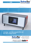
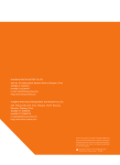
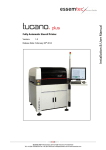
PCU1000 user manual Handbuch PCU1000 Display and readout system PCU1000 Vögtlin Instruments AG – flow technology Langenhagstrasse 1 | 4147 Aesch (Switzerland) Tel. 41 (0)61 756 63 00 | Fax +41 (0)61 756 63 01 www.voegtlin.com | [email protected] PCU1000 PCU1000 user manual Version: pcu1000_E1_3 For the latest information on our products, see our website at www.voegtlin.com © 2009 Vögtlin Instruments AG, Switzerland Manual Version PCU1000 pcu1000_E1_3 Page © Vögtlin Instruments AG 02 PCU1000 Table of revision Datum Version 08.06.09 pcu1000_E1_3 pcu1000_E1_2 MRZ 07.06.09 pcu1000_E1_2 Manual Version PCU1000 pcu1000_E1_3 Ersetzt Autor Notiz Deviation alarm Page © Vögtlin Instruments AG 03 PCU1000 Contents Introduction 5 Benefits to the user 5 Service and Quality 5 Warranty 6 Instructions and warnings 6 Contents of the manual 6 General information 7 Design of the electronic analysis system 7 Technical data 8 Power supply units 8 Storage of the settings 9 Pin configuration of the panel mount device 9 Pin configuration of the desktop device 9 Assembly and installation 10 General instructions 10 Environment 10 Installation instructions 10 Power supply units 10 Panel mounting 10 Functions 11 Introduction 11 Status indicators 11 Operating modes 11 Display and setting functions 12 Mixer configuration 17 Channel configuration 18 Commissioning 20 Entering the password 20 Selecting languages 20 Allocating channels 20 Channel configuration 21 Setting the set value in the „Individual‟ operating mode 21 Mixer operation 21 Appendix 22 Desktop device dimensions 22 Control panel cut-out dimensions 23 Manual Version PCU1000 pcu1000_E1_3 Page © Vögtlin Instruments AG 04 PCU1000 Introduction The Process Control Unit PCU1000 complements the red-y smart device series. It enables users to control and visualize mass flow meters and controllers in situations where control via a PC or PLC is neither desired nor available. This manual will familiarize you with the installation and operation of the PCU1000. Read the manual carefully before commissioning the device. Please contact your distribution partner if anything is not clear. We have taken great care in compiling this manual. However, we can accept no responsibility for any mistakes. Benefits to the user Ultimately, technology is only ever a means to an end. For this reason one thing remains paramount in all our developments: The user who is working with the measuring device. All our efforts are directed towards meeting the needs and requirements of the users and their measuring or control task: Compact, easy to install electronic analysis system Connection to up to 10 mass flow meters and controllers or pressure controllers Automatic recognition of connected devices Numerical set point presetting Display of the process variable and total flow Gas mixer function with up to 12 recipes LCD display (backlit) Touch screen operation Menu-driven user interface in several languages Panel mount or desktop versions Service and Quality We are continually improving the quality and provision of our products and services. In the end, whether the right product was selected only becomes apparent once the product is in use. Therefore we make every effort not just to preach but also to live by top quality and service. Manual Version PCU1000 pcu1000_E1_3 Page © Vögtlin Instruments AG 05 PCU1000 Warranty Warranty for products in the „red-y for gasflow‟ range extends to material and manufacturing defects. Maximum warranty covers product replacement free of charge. All claims are excluded in the event of improper use, external interference in general, heat or accidental fall. We are always grateful for information on any existing defects, suggestions for improvement and criticism. Instructions and warnings Read all of the operating instructions thoroughly before commissioning a device. Incorrect use, misunderstandings and the consequences of these can result in destroying the device and even endangering people. Commissioning and maintenance must only be carried out by appropriately qualified personnel. Proper use of the products is a necessary precondition for their smooth operation. Electrostatic discharges can destroy the electronic components of the electronic analysis system. Contents of the manual This manual will instruct you on how to use the PCU1000 electronic analysis system safely. Manual Version PCU1000 pcu1000_E1_3 Page © Vögtlin Instruments AG 06 PCU1000 General information Design of the electronic analysis system The PCU1000 was specially developed for use with red-y smart series controllers and meters. It enables easy display and control of these devices in situations where neither a PC nor a PLC is available or desired. The PCU1000 communicates with up to 10 meters or controllers in any combination via an RS485 interface. Operation is menu-driven via an LCD backlit touch screen. The operating interface is available in several languages and designed so that the user will be able to cope easily straight after a short introduction. In addition, password-protected access levels can prevent operating errors. The PCU1000 is available in two versions as panel mount or desk-top device. The electrical connections are pluggable and accessible from the back in either version. The power supply for the device and connected red-y smart is 24 Vdc. Power supply unit and bus cables are included in delivery with the desk-top version. Manual Version PCU1000 pcu1000_E1_3 Page © Vögtlin Instruments AG 07 PCU1000 Technical data General device specifications Display LCD display (monochrome) with integrated backlighting Keypad Touch screen Number of channels 10 channels, each for controlling a red-y smart series device Housing Panel mounting: Dimensions: 173 x 114 x 50mm Desktop housing: Dimensions: 252 x 190 x 197mm Power supply 24 Vdc +/-5% Power consumption Type 350 mA Temperature range Operation: 0 – 50°C Storage: -10 – 60°C Panel mounting: Front IP64, depending on mount Protection class Desktop device: IP50 EMC EN50081-2, EN50082-2 Connections Panel mounting: Pluggable screw terminals Power supply Desktop device: Socket for power supply unit RS-485, Modbus protocol Panel mounting: Pluggable screw terminals Desktop device: Sub D 9-pin Power supply units Panel mounting: The PCU1000 and connected devices can be powered from the same 24 V source. Desktop device: The devices connected via the bus cable are powered by the PCU1000. Warning: Do not exceed the maximum number of devices according to the red-y smart series manual (approx. 10 devices incl. PCU can be powered by the 2.2 A power supply unit). Manual Version PCU1000 pcu1000_E1_3 Page © Vögtlin Instruments AG 08 PCU1000 Storage of the settings In the event of outage, the set parameters are powered by a back-up lithium battery. In regular operation, the battery lasts approx. 10 years. Pin configuration of the panel mount device RS232 (Service connection, not used) RS485 A+ BBlank (screen) Rx A+ Rx BTx A+ Tx B- USB (Service connection, not used) Power supply 24 Vdc + Ground Blank (screen) Pin configuration of the desktop device Power supply 24 Vdc, GND + (Tip) - (Ring) RS485 (9-pin Sub D connector, neg.) 1 not used 2 - 24Vdc 3 + 24Vdc 4 not used 5 not used 6 Rx+, RS485 (A) 7 Rx-, RS485 (B) 8 Tx-, RS485 (B) 9 Tx+, RS485 (A) Manual Version PCU1000 pcu1000_E1_3 Page © Vögtlin Instruments AG 09 PCU1000 Assembly and installation General instructions Check the package for external damage and contact us immediately if there is visible damage. Check the package contents against the delivery note to see that they are complete and conform to the technical specifications. This product is a top-quality electronic display unit. We would like to point out that you should take due care when choosing the installation site and following these suggestions and instructions. Environment The electronic analysis system is so designed that it can be used in a variety of ways. The devices must not be used under the following environmental conditions: Environments with a high degree of conductive dust, mist, rain, direct solar radiation, great heat, strong shock waves and vibrations. Take care to prevent water and foreign objects getting into the electronics. Install the electronics as far away as possible from high tension cables and inductive consumers. Installation instructions We recommend that you use our connecting cables. If you assemble the cables yourselves, please observe the national regulations and safety regulations in force. Make sure the cable has a sufficient cross-section, especially with longer cables. An appropriately shielded twisted signal cable must be used for the bus cable. Avoid ground loops and do not lay the cables parallel to mains leads if possible. Leads which may interfere with the device should be crossed at an angle of 90 °. Power supply units The PCU1000 can only be powered by a regulated power supply unit with 24 Vdc. The connected measuring and control devices must have the same reference potential to avoid damage from electrical surge. Panel mounting For information on control panel cut-out and mounting holes, see appendix. Manual Version PCU1000 pcu1000_E1_3 Page © Vögtlin Instruments AG 10 PCU1000 Functions Introduction After the self-test, the PCU1000 always starts up with the main display window, so that the connected measuring and control devices and their operating status are visible at once. If no devices are connected, the last device connected to the relevant channel is shown and „?????‟ is displayed in place of the actual value. Tapping on the relevant fields on the touch screen brings you to the submenus provided these are not password-protected. A touchs creen keypad for inserting numerical values or IDs will appear automatically. The device can operate up to 10 controllers and meters at the same time. The individual channels are referenced with V1-V10 and an individual measuring point ID. Status indicators The following status indicators are displayed on the front of the device: POWER A green light lights up when the device is switched on. MIXER A green light lights up when the „Mischung ein/aus‟ (Mixer on/off) key is switched to „ein‟ (on). ALARM A red light lights up when a fault or alarm status has been registered in the PCU1000 or a connected device. Operating modes Individual: Each channel, i.e. each connected device is separately operated. Fixed value mixer: The channels (controllers) included in a recipe are controlled according to the percentage of the main set value allocated to them. Master/slave mixer: The channels included in a recipe are controlled according to the percentage of the measured value of the reference channel allocated to them. The reference channel (the reference device) can also be a meter. Manual Version PCU1000 pcu1000_E1_3 Page © Vögtlin Instruments AG 11 PCU1000 Display and setting functions Main display window Shows the following data per channel (connected device): Measuring point ID or device ID Measured value Set value (if the connected device is a controller) If a „!‟ appears in front of the channel number, this means that there is a fault in the relevant control loop or communication with the device or that alarm status has been registered. For details, see „Detailed display of a channel‟. If more than 5 devices are connected, the next page with channels V6-V10 can be displayed by tapping the „weiter‟ (Next) key. Tapping the „weiter‟ (Next) key again displays the totalizer values of the connected devices. Tapping the „init Vn‟ key resets the totalizer T1 of the relevant device to zero. The operating control bar contains the following key fields: MENU: next into the submenus Name of the chosen mix MIX on and off: Starts and stops a mixing process in the mixer operation or starts and stops the control of the connected controllers when the „Synchro‟ function is selected in individual operation. Manual Version PCU1000 pcu1000_E1_3 Page © Vögtlin Instruments AG 12 PCU1000 Detailed display of a channel Tapping the „Vn‟ key opens the detailed window of the appropriate channel with the following functions: (These settings are only possible with level 2 or 3 passwords) Setting the set value of the connected controller: Tapping the set value field opens the window with a numerical keypad, for setting the desired value and confirming this with „Ent.‟. Touch „Korr‟ (Corr) to erase an incorrectly entered value. Press „Annull‟ (Cancel) to leave the menu item without changing the set value. Error messages: „No communication‟ between the PCU1000 and the connected device. „Deviation from measured value‟, i.e. the difference between the set value and the actual value is above the set limits and the control function will not work. This error message can be acknowledged by tapping the „Quittieren‟ (Acknowledge) key. ‘Synchro’ function The channels where the „Synchro‟ function is switched on are always switched on and off at the same time in the individual and mixer operations. For this, press the „Mixer on/off‟ key in the main display window. If one channel is not operating, the other channels will be switched off as well. If „/Synchro‟ appears in the field, the function is switched off. Details of the connected device, such as: Measuring point ID, type code, serial number, measuring range and gas type. In addition, the „Internal set value‟, i.e. the set value set in the controller and the „Sensor temperature‟ of the controller are displayed. Manual Version PCU1000 pcu1000_E1_3 Page © Vögtlin Instruments AG 13 PCU1000 Configuration menu Pressing the „MENU‟ key in the main display window brings up the following submenu list: Configuration access code System configuration Mixer configuration Channel configuration In addition, the alarm list can be viewed with the „Warnungen‟ (Warnings) key. Configuration access code Tapping this field brings up the numerical keypad for entering the password. This must be confirmed with „Ent.‟ or canceled with „Annul‟ (Cancel). After entering the password successfully, „Niv.2‟ or „Niv.3‟ (Level 2 or Level 3) appears according to the password level released. After 15 minutes the device returns to blocked status again, unless the password 0 was configured. Only the following settings are possible without entering a password: Mixer „on‟ or „off‟ Acknowledge alarm Select screen saver Time and date Password allocation: See password levels under „System configuration‟. Manual Version PCU1000 pcu1000_E1_3 Page © Vögtlin Instruments AG 14 PCU1000 System configuration Tapping system configuration enables the following settings: Activate the screen saver, by tapping the „Schaltet nach 1 Stunde aus‟ (Switches off after 1 hour) field. Setting the time and date. If password level 3 was activated, 2 more fields appear. Init.BD: With this the internal database can be reset to the original settings. Warning: If the entry is confirmed by tapping „Init.BD‟ again, all data relating to the connected devices, recipes etc. will be lost and must be re-entered once more. Next: This allows the following settings: Language: Tapping the field enables switching between German, English and French. Bus size: This defines the number of active channels, so that no empty lines are shown in the main display window. Maximum bus size and therefore maximum number of connected devices: 10 Pass level 2: The level 2 password is defined here. Factory setting: 1234 Pass level 3: The level 3 password is defined here. Factory setting: 561 Manual Version PCU1000 pcu1000_E1_3 Page © Vögtlin Instruments AG 15 PCU1000 Find new red-y: Every device must be individually connected to the bus, so that it can be detected by the PCU1000 and allocated to a channel. Tapping the „Suche‟ (Find) field scans the bus and displays the located device with its bus address, serial number etc. The device must now be defined as „Mass flow controller‟, „Mass flow meter‟ or „Pressure controller‟. The measuring point ID is entered in the „Text‟ field. The desired channel is identified in the „Kanal‟ (Channel) field and allocated to the connected red-y by tapping the „Zuteilung‟ (Allocation) field. Successful allocation is confirmed with „ ok‟. Manual Version PCU1000 pcu1000_E1_3 Page © Vögtlin Instruments AG 16 PCU1000 Mixer configuration One of the maximum 12 recipes can be selected with the level 2 password and activated with „Rezept aktivieren‟ (Activate recipe). The recipes can be issued and changed with the level 3 password: The recipe name is entered in the field next to the recipe number. Selecting the operating mode: Tapping the „Betriebsart …‟ (Operating mode) field switches between the different operating modes: Individual Even when operating individually, the connected devices form part of a recipe. All the devices appear in the main display window automatically, provided they are not suppressed by the number of displayed channels. The set point presetting is individual. Fixed value mixer Tapping the „Zuordnung der Kanäle‟ (Allocating the channels) field selects the channels belonging to this mix and identifies the appropriate percentage of the total flow. The sum must add up to 100% exactly. The set value of the total flow can be set with the level 2 password. Master/Slave mixer Tapping the „Zuordnung der Kanäle‟ (Allocating the channels) field selects the channels belonging to this mix and identifies the appropriate percentage of the master‟s measured flow. The leading set value is that of the „Master‟, i.e. of channel 1, and can also be set with the level 2 password. Manual Version PCU1000 pcu1000_E1_3 Page © Vögtlin Instruments AG 17 PCU1000 Channel configuration Further details of the selected channel can also be configured with the level 3 password. Zero suppression The minimum displayed value is defined in the „Mini x%‟ field. Below this value, the connected controller is considered to have stopped. In „Master/Slave‟ mode, the master‟s flow must be above the minimum value to enable the mixer to start. Deviation alarm The set/actual difference is defined in the „Abw. M/S = x%‟ (Deviation M/S = x%) and „=> y sec‟ field, also the delay after which the deviation alarm for this channel will be activated. If the following fields show „Val‟ and „Stop‟, the channel is stopped, i.e. the set value is set at 0. „/Stop‟ deactivates this function. The calculation of the deviation range is shown in the formula below DeviationRange Range Dev.M / S 100 DeviationRange 60 ln/ min 5% 100 3l / min Example: -> using the calculation above with a 60ln/min device, a setpoint of 10ln/min is valid in the range of 7ln/min to 13ln/min. If measurements are outside this band a Message will occur „Messwertabweichung”(Measurement deviation) and if Val“ et „Stop“ is activated the setpoint will be set to zero after the delay time has expired. Manual Version PCU1000 pcu1000_E1_3 Page © Vögtlin Instruments AG 18 PCU1000 Communication errors The time delay for a communication error with the connected device is set in the „Komm.Fehler=xsec‟ (Comm. errors=x sec) and „Stop‟ field. If the field shows „Stop‟, a mix is stopped. Multi LUT switching If a connected red-y has several data sets for fields (Multi LUT), these can be selected with the „Fluid n‟ field. Manual Version PCU1000 pcu1000_E1_3 Page © Vögtlin Instruments AG 19 PCU1000 Commissioning Preparing the red-y smart series devices to be connected by means of get red-y software, i.e. setting the bus address correctly and optimizing the control loop beforehand if necessary, is recommended. Given the correct bus address (1 to 10 max.); the PCU1000 will recognize the devices immediately, so that each device need not be connected individually. Entering the password After switching on the PCU1000, the main display screen appears which may already contain data from the channels being used depending on its configuration status. The flashing alarm LED need not be heeded. Adjustments to the configuration can be made after entering the level 3 password. Press the „Menu‟ key, then „Configuration access code‟, enter the code (factory setting 561) and press „Ent‟ to confirm. Changing passwords: see System configuration. Warning: The PCU1000 returns to blocked status after 15 minutes. Selecting languages Switching between d (German), f (French) and e (English) is possible if required. Press the „Menu‟ key, „Systemkonfiguration‟ (System configuration), „Weiter‟ (Next) and then set the „Sprache: ...‟ (Language) field. Allocating channels If the device addresses were not configured, then each device will have to be connected to the bus and allocated to a channel separately. Press the „Menu‟ key, „Systemkonfiguration‟ (System configuration), „Weiter‟ (Next), and „Find new red-y‟. Enter the number of red-ys to be connected in the „Busgrösse: ...‟ (Bus size) field. Enter the desired channel (= bus address) in the 'Kanal' (Channel) field. Select the device type, i.e. select Mass Flow Meter, Mass Flow Controller or Pressure Controller. Enter the measuring point ID in the „Text‟ field. Press the „- Zuteilung„ (Allocation) key. If the address of the located device matches the channel number, the field switches to „- ok‟; if not, „- run‟, the scanned address and „Keine Kommunikation‟ (No communication) appear. Press the „Suche‟ (Find) key: If the channel and address number match, press the „- Zuteilung„ (Allocation) key again. Manual Version PCU1000 pcu1000_E1_3 Page © Vögtlin Instruments AG 20 PCU1000 Channel configuration Press the „Menu‟ key, „Kanalkonfiguration‟ (Channel configuration), „Kanalnummer‟ (Channel number) and carry out the following adjustments if necessary: Choice of calibration curve in Multi LUT devices: Press „Fluid y‟ key Setting the bottom level in the measuring range: „Mini x%‟ field Setting the deviation alarm function Setting the communication error function Setting the set value in the ‘Individual’ operating mode For this, level 2 or level 3 passwords must be entered. In the main display window select the desired channel with the „Vn‟ key and enter the desired set value in the „Set value‟ field. The Synchro function is also activated in this submenu. Mixer operation The level 2 password must be entered to select a recipe and the level 3 password to identify a recipe. Identifying a recipe: Press the „Menu‟ key, then „Mischerkonfiguration‟ (Mixer configuration). Enter the recipe number in the „Rezept n/12‟ (Recipe n/12) field, select 1/12 to 12/12 and enter the recipe name in the next field. Select the operating mode in the „Betriebsart ...‟ (Operating mode) field, then „... Mischer fix‟ (Fixed value mixer) or „... Master/Slave‟. Press the 'Zuordnung der Kanäle' (Allocating the channels) key and enter the appropriate channels with the corresponding % proportions. Enter the set value in the „Gesamtfluss‟ (Total flow) field in the „Mischer fix‟ (Fixed value mixer) operating mode. Press the „Rezept aktivieren‟ (Activate recipe) key. The name of the activated recipe now appears in the main display and the mix can be switched on or off with the „Mischung ein aus‟ (Mixer on off) keys. The LED „MIXER‟ lights up when the mixer is running. The set value must be entered in channel 1 (= Master) in the „Master/Slave‟ operating mode. The channels allocated as slaves follow the master according to their configured percentage of the measured value. For this reason the master can also be a meter instead of a controller. Manual Version PCU1000 pcu1000_E1_3 Page © Vögtlin Instruments AG 21 PCU1000 Appendix Desktop device dimensions Manual Version PCU1000 pcu1000_E1_3 Page © Vögtlin Instruments AG 22 PCU1000 Control panel cut-out dimensions Manual Version PCU1000 pcu1000_E1_3 Page © Vögtlin Instruments AG 23