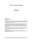
1
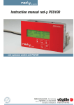
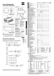
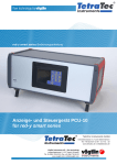
Instruction manual red-y PCU800
red-y process control unit PCU800
Vögtlin Instruments AG – flow technology
Langenhagstrasse 1 | 4147 Aesch (Switzerland)
Phone +41 (0)61 756 63 00 | Fax +41 (0)61 756 63 01
www.voegtlin.com | [email protected]
Instruction manual red-y PCU800
process control unit PCU800
Copyright © 2006 Vögtlin Instruments AG, Switzerland
Version: pcu800_E2_0
Text: Daniel Walliser, Christian Mahrer
Translation: Hans Etter, P.T.S GmbH
Design: Michael Huber
The latest news about our products you will find on www.red-y.com
Vögtlin Manual
red-y PCU800
Version
pcu800_E2_0
Chapter
Page
00
2
Table of Contents
01 Introduction
4
User Benefits
Service & Quality
Warranty Services
02 General Information
6
Design of the Readout & Control System
03 Technical Specifications
7
General Device Specifications
Inputs & Outputs
Power Supply
Saving the Settings
Connector Pin Assignments
04 Mounting & Installation
10
General Remarks
Environment
Installation Tips
05 Functions
11
Introduction
Keyboard Functions
Menu Structure Overview
List of Functions
06 Operation & Service
22
Turning the System On
Procedure at First PowerUp
Warm-up Time
Operation
Replacing the Battery
07 Troubleshooting
08 Dimensions
23
24
Front Panel Installation
Table Casing
Vögtlin Manual
red-y PCU800
Version
pcu800_E2_0
© Vögtlin Instruments AG
Chapter
Page
00
3
Introduction
01 Welcome
The electronic process control unit red-y PCU800 is a high-end readout and control system for flow
measurement. A modular concept with various connection options offers you the highest possible
degree of integration and safeguard for the future.
This manual will familiarize you with the installation and operation of your red-y PCU800. Please
read this manual carefully and contact your sales partner for questions or clarifications.
We took great care in compiling this manual to offer you correct and accurate information and
instructions. However, we cannot be held responsible for possible errors.
User Benefits
Ultimately, technology is always a means to an end. Therefore, our priority in development is always
the same: the user operating the measuring equipment. All our efforts are guided by the needs and
requests of the users and their measuring and control tasks:
- Compact electronic readout and control system that is easy to install
- Intuitive operation with numeric keyboard
- Large, easily readable, back-lit display
- Integrated help function
- CE certified
- Optional field bus connection
- Optional freely configurable digital inputs and outputs
- Implements the full functionality of the connected measuring and control devices
- Easy to maintain and service
- Easy functionality expansion
- 3 years guarantee
- Adapted options and accessories
Service & Quality
We are continuously improving the quality and the service of our products and performances. Only
when using a product, you will see if you chose the right product. For this reason, we strive to not
only propagate good service and high quality, but to live it every day.
Warranty Services
The warranty for the 'red-y for gasflow' product line covers material and manufacturing faults. The
maximum amount covered by the warranty services is limited to free replacement of the device.
Improper use, general external damages and damages due to heat or falls void all warranty claims.
We welcome reports of possible errors, suggestions for improvement and criticisms.
Vögtlin Manual
red-y PCU800
Version
pcu800_E2_0
© Vögtlin Instruments AG
Chapter
Page
01
4
Introduction
Suggestions & Warnings
This user manual should be read in full before start-up of the device. Improper use,
misunderstandings and their consequences may destroy the device and even cause bodily harm.
Commissioning and maintenance must be performed by appropriately qualified staff. Proper use of
the products is essential for their trouble-free operation.
Electrostatic discharges may destroy electronic components of the red-y PCU800.
Content of the Manual
This manual will instruct you in the safe use of the readout and control system red-y PCU800.
Vögtlin Manual
red-y PCU800
Version
pcu800_E2_0
© Vögtlin Instruments AG
Chapter
Page
01
5
General Information
02 General Information
Design of the Readout & Control System
The red-y PCU800 is specifically designed for use with thermal mass flow meters and controllers.
The electronic system offers the user the full functionality of the connected measuring and control
devices and supplements it with selected additional options.
The PCU800 powers up to eight attached measuring and control devices and communicates through
the included RS-485C interface.
Its basis is an optimized I/O control panel, which is already being used successfully in the field. A
high-end, graphic back-lit LC-display and the keyboard create the interface with the user operating
the devices in the field.
An integrated help function assists the user. Together with this manual, it is easy to make full use of
the functions of the red-y mass flow meters and controllers and the PCU800.
The operation of the individual menus and settings is the same as the standard Windows user
interface.
The electronic system includes a CAN interface. This enables your red-y mass flow meter and
controller to communicate with the world of fieldbus communication. Optionally, the system may
additionally be equipped with a complete range of I/O modules.
The highly compact casing can be easily integrated into a control panel. All connections are
accessible from the back and are pluggable. There is therefore no need to wire the device before
installation.
A tabletop case with a power pack is available as an option. This reduces the effort for the start-up
to a minimum.
The digital communication between the mass flow or controller and the PCU800 also significantly
reduces the programming efforts. The only settings that the user may need to define are the limit
settings or the function of the I/O channels. All other required parameters are automatically queried
from the mass flow meter or controller by the PCU800.
Vögtlin Manual
red-y PCU800
Version
pcu800_E2_0
© Vögtlin Instruments AG
Chapter
Page
02
6
Technical Specifications
03 Technical Specifications
General Device Specifications
Display
Keyboard
Case
Dimensions
Voltage supply
Power consumption
Temperatures
Storage
Operation
Protection class
EMC regulations
Graphic LC-display (monochrome)
with integrated back-lighting
Numeric keys with double assignment
for text input or control
Additional keys for controlling the cursor
Suitable for control panel installation with locking bolt
Control panel cut-out: min. 187 x 79 mm
195 x 120 x 45 mm (W x H x D), see appendix
24 Vdc with reverse polarity protection
4–7W
-10 °C to 60 °C
0 °C to 50 °C
According to EN61131-2/VDE0631, part 1,
protective low voltage
EN50081-2 and EN50082-2
Inputs and Outputs
RS-485C Modbus
Flow meter or controller
CAN interface
Field bus connection (ISO 11898)
Voltage supply
Sub-D 9-pin, female
Sub-D 9-pin, male
3-pole plug connector with inverse-polarity protection
Power Supply
If the PCU800 is powered with +24 Vdc, the mass flow meter or controller is automatically supplied
with power without additional wiring (galvanically separated).
Saving the Settings
The memory components are supplied by an auxiliary battery in case of a power loss. The lifetime is
typically 5 years. The battery can be purchased in specialized stores and can be replaced by the
user.
Vögtlin Manual
red-y PCU800
Version
pcu800_E2_0
© Vögtlin Instruments AG
Chapter
Page
03
7
Technical Specifications
Connector Pin Assignment Modbus/RS-485C Interface
This connector powers the mass flow meter or controller and provides data communication with the
PCU800.
5
4
3
2
9
8
7
6
1
Pin
Assignment
1
2
3
4
5
6
7
8
9
not used
GND
Supply +24 Vdc
not used
not used
Rx+ RS485 (A)
Rx- RS485 (B)
Tx- RS485 (Z)
Tx+ RS485 (Y)
Connector Pin Assignment CAN-ISO 11898 Interface
This connector can be used to connect the PCU800 to a superordinated CAN fieldbus. The
connection is designed with galvanic separation and an integrated terminating resistor pursuant to
ISO 11898. If the device is to be used as the last segment in a CAN network, contact your sales
partner (activation of terminating resistor).
5
4
3
2
9
8
7
6
1
Pin
Assignment
1
2
3
4
5
6
7
8
9
not used
CAN data low dominant
GND (Signal Ground)
not used
Shielded wire
GND (Signal Ground)
CAN data high dominant
not used
not used
Connector Pin Assignment Supply Voltage
The connector is secured with the clips on the side. To remove the connector, both clips must be
pressed at the same time and the connector must be removed towards the top. The strands are
clamped in by a spring mechanism. This mechanism can be operated with a screw driver in the
respective opening beside it.
1
2
3
Vögtlin Manual
red-y PCU800
Version
pcu800_E2_0
© Vögtlin Instruments AG
Pin
Assignment
1
2
3
+ 24 Vdc
not used
GND
Chapter
Page
03
8
Technical Specifications
Connector Pin Assignment for Digital inputs and Outputs (optional)
Each port is assigned an LED. For the inputs, the LEDs illuminate if the signal level is high. For the
outputs, they illuminate if the output is active.
1
2
3
4
5
6
7
8
9
Pin
Assignment
1
2
3
4
5
6
7
8
9
10
Load GND 0 V
Input 4
Input 3
Input 2
Input 1
Output 4
Output 3
Output 2
Output 1
Load voltage supply, typically 24 Vdc
(18...30 Vdc) residual ripple max. 5%
10
Connection Diagram for Digital Outputs
1
2
3
4
5
6
7
8
9
10
7
8
9
10
–
ULast +
Connection Diagram for Digital Inputs
1
2
3
4
5
6
–
ULast +
Vögtlin Manual
red-y PCU800
Version
pcu800_E2_0
© Vögtlin Instruments AG
Chapter
Page
03
9
Mounting & Installation
04 Mounting & Installation
General Remarks
Check the package for external damages and contact us in case of visible damages. Compare the
contents of the package with the delivery note and check for completeness and technical
agreement.
This product is a high-end electronic display unit. We recommend that you choose the installation
location carefully and observe the following suggestions and remarks.
Environment
The PCU800 has been designed for manifold uses. Under the following environmental conditions, the
device may not be operated:
Environments with a high degree of conductive dust, mist, rain, direct sun, excessive heat, strong
blast waves, and vibrations. Make sure that no water or foreign objects can enter the casing.
Install the PCU800 as far away as possible from high-voltage wires and inductive loads.
Installation Tips
Connection and installation of the PCU800 must be performed by an electrical specialist. National
rules and applicable safety regulations must be observed.
All connection wires must be insulated to prevent contact with live parts.
The input and output wires must not be located close to high-voltage lines.
Observe voltage drops and interferences if the input and output lines are laid across large distances.
Ensure that correctly gauged wires are used for the connections.
If the PCU800 is used in an environment according to EMC directive EN55011-Class B, ferrite cores
must be installed in the power supply line as well as in the CAN network connection. Please contact
your sales partner.
Specification of the Connection Wires
For the input and output connections, use wires with a size of 0.5 mm2 - 2.5 mm2. Strip 7 mm off the
wire endings. Open the pinch clamp before inserting the conductors. Insert the conductors into the pinch
clamp so that a secure connection is ensured.
Re-tighten the pinch clamp so that the conductor cannot be pulled out. Do not exceed a torque of 5 Nm
to avoid damaging the conductors. Use wire end sleeve for flexible leads.
Power Supply
The devices must be operated with suitable 24 Vdc power supply units (see technical
specifications). They must not be connected directly to the mains line!
Control Panel Installation
To attach the PCU800, it is pressed together with the control panel, using 4 locking bolts. It is
therefore not necessary to drill mounting holes.
Vögtlin Manual
red-y PCU800
Version
pcu800_E2_0
© Vögtlin Instruments AG
Chapter
Page
04
10
Functions
05 Functions
Introduction
All functions are embedded in a menu structure. Based on the Microsoft Windows standard, the
submenus are selected and inputs are made. After PowerUp (turning on the supply voltage) and the
execution of various test functions, the main display (main menu) appears. Depending on the display
settings and the bus size, this window shows the most important operational values. This window is
the basis window. From here you can access all available submenus.
The PCU800 can control up to 8 mass flow meters or controllers simultaneously. These devices are
identified by the numbers 1-8. These numbers also correspond to the bus address.
Keyboard Functions
The keys C, OK and the four arrow keys are used for navigating within the menu structure. The
numeric key block can be used to enter numerical values easily. Depending on the entry field, the
numeric key block can also be used to enter letters. This is done similarly to entering letters on a
phone keypad.
In addition, the 9 (symbol = ? ) can be held down to access a context help menu.
Within a menu there are different data fields:
Information is shown in information fields and cannot not be changed (e.g. serial numbers, etc.)
Entry fields that provide a pre-defined selection. These values are listed in a pull-down menu
and can be selected with the arrow keys and . To confirm the selection, press the OK key.
Entry fields that require a value. This value is entered with the numeric keypad and likewise
confirmed with the OK key.
The active data field is always shown inverted (black background).
Vögtlin Manual
red-y PCU800
Version
pcu800_E2_0
© Vögtlin Instruments AG
Chapter
Page
05
11
Functions
Menu Structure Overview
Vögtlin Manual
red-y PCU800
Version
pcu800_E2_0
© Vögtlin Instruments AG
Chapter
Page
05
12
Functions
List of Functions
Main menu
The main menu is the basis for the menu structure. All
operating steps and settings are accessible from here. When
the device is turned on, this menu is shown automatically.
In the Display Mode menu, the contents of the Main Menu can
be defined. Depending on the system size (number of devices)
and application, entirely different contents may be displayed
here. The left column shows two samples.
Enabled Settings
C
OK
1-8
This key opens a menu, which allows making settings for the
corresponding device.
Open Setpoint Menu
If only one device is shown in the main menu (e.g. graph
display), these keys can be used to display another device.
When selecting the device directly, identified by its bus
address, the Settings Menu for the selected device is shown
directly.
Set points
Settings menu for the flow set point. After opening this menu,
the setpoint can be modified.
Enabled Settings
Set point: 365.0 mln/min
Entering the set point in the corresponding resolution
Settings
The C key is used to go to the Selection Menu, where the
device is selected, for which the settings are to be changed.
After selection and confirmation with OK , the cursor jumps to
the menu option [smart].
Under the menu point [PCU800], you can adjust the settings
for the display unit.
Enabled Settings
OK
Vögtlin Manual
red-y PCU800
Version
pcu800_E2_0
© Vögtlin Instruments AG
Select the active device
Activate the menu or an entry
Chapter
Page
05
13
Functions
Flow meter or controller settings
You can move around in the selection with the cursor (arrow
keys). The selection is confirmed with the OK key.
Enabled Settings
Set points
Control functions
Totalizer
Limits
Information
Settings menu for the set point
Submenu for making adjustments to control parameter,
setpoint source and PowerUp setpoint
Read and reset the totalizer and the sub-total
Settings for the two alarm values and zero suppression
Display of the most important parameters of the meter or
controller
Display unit settings
You can move around in the selection with the cursor (arrow
keys). The selection is confirmed with the OK key.
Enabled Settings
Event list
System
Inputs and outputs (optional)
Gas Mixer (Optional)
Display of alarms and status messages
Customize the display form in the main menu, change the bus
structure and activate the password protection
Settings for the optional I/O module
Mixer functions
Control mode
Define the set point presetting. Use the and key to
switch between the individual set values. The OK key confirms
the selection.
Enabled Settings
auto
digital (default)
analog
closed
Flush
Vögtlin Manual
red-y PCU800
Version
pcu800_E2_0
© Vögtlin Instruments AG
The control device disregards any analog set point presettings
that are fed externally directly into the red-y PCU800
The set point is defined by the red-y PCU800
In this mode, the device only uses set point presettings that
are directly fed to the device as analog values
The valve is held closed
The control is disabled and the valve is opened to the
maximum. This can create a large flow that exceeds the
measuring capacity. It is used for flushing or flooding
processes for example
Chapter
Page
05
14
Functions
Control parameters
Six entry fields in total are available for selection. Five control
parameters are stored per control parameter set. For the sets
User 1 and User 2, they can be individually adapted to the
application. After opening the menu, use the or key to
select the corresponding set and confirm it with the OK key.
Use the or key to go to the next entry fields. For
numerical values, use these keys to select the position first
and change the value with the or key. Confirm the entry
with the OK key.
With setpoint step, you can adjust the setpoint in 10% steps.
Enabled Settings
Set: Fast
Set: Medium
Set: Slow
Set: User 1
Set: User 2
Kp:
Tn:
S:
N1:
F:
%step
Fast response time with corresponding overshooting (fast
response)
Medium response time with slight tendency to overshoot
Slow response time without overshooting
Can be adjusted individually by customer
Can be adjusted individually by customer
Amplification factor of the controller
Time constant of the controller
Search speed PWM
Offset compensation
Feed forward rate of the controller
Setting the set point in 10% steps. Upon confirmation with the
OK key, the selected % value is converted to the technical unit
and saved as the set point. The entry field % step shows 'off'
again.
Power up Setpoint
Defines the set point when the controller is powered up.
Important:
The set point is only used in the digital control mode
Enabled Settings
activate: on
Set: 100.00 mln/min
Turns the function on or off
Determines the set point automatically used after a power
loss.
Sub Total
The sub total is a subset of the total. With every reset, the
current totalizer value is stored and subsequently deducted
from the current totalizer value. This could be compared to the
trip odometer in a vehicle. The PCU800 will recognize a newly
connected red-y device and clears the stored totalizer value to
calculate the sub total.
As the sub total is displayed in the main menu, the sub total
can be synchronized with the totalizer.
Enabled Settings
0 = clear
OK = adapt
Vögtlin Manual
red-y PCU800
Version
pcu800_E2_0
© Vögtlin Instruments AG
The sub total is synchronized with the total
Reset the sub total
Chapter
Page
05
15
Functions
Totalizer
Total quantity of gas since the last reset
Enabled Settings
0 = clear
Pressing the [0] clears the total and the counter is reset to
zero
Creep quantity
Set a threshold value. Below this value, zero is displayed for
the flow.
Enabled Settings
OK = confirm value
Set the treshold value and confirm it with OK
Alarm 1/2
Select the mode of operation of the alarm and set the alarm
value, the hysteresis, the delay time and the reset type.
The following settings options are the same for both alarms.
Enabled Settings
Function: low
Function: high
Alarm: 30.00 mln/min
Hysteresis: 00.0%
Delay: 0s
Reset auto
Reset manu
Vögtlin Manual
red-y PCU800
Version
pcu800_E2_0
© Vögtlin Instruments AG
Flow values below the threshold value are interpreted as an
alarm
Flow values above the threshold value are interpreted as an
alarm
Setting the threshold value. Depending on the function,
current flow values above or below this value are interpreted
as an alarm
If the current flow and the set threshold value are close
together, the hysteresis setting can prevent the alarm from
turning on and off continuously. The value may be between
0 - 10% of the maximum end value
The time can be set between 0 and 180 seconds and
represents the time the alarm state must persist for the alarm
contact to be triggered. This prevents the alarm from being
triggered if the measured value drops below, or exceeds the
threshold values briefly
The alarm state is automatically reset after the current flow
returns to the corresponding desired range
The alarm state remains active until it is either acknowledged
in the event list or reset by a correspondingly defined external
input
Chapter
Page
05
16
Functions
Information
Information about the selected red-y
Event List Settings
Settings for the display of the event list
Enabled Settings
OK = show list
Alarm List Auto
Alarm List Manu
Opens the window with the event list
If an event occurs, the window with the event list is displayed
automatically
The events are stored in the background
Event list/status messages
The messages listed give information on important events or
error messages generated by the devices directly. The digit
shown after the word Status corresponds to the sum of the
possible errors listed in the following:
Enabled Settings
1
2
4
8
16
32
64
128
256
512
1024
PowerUp Alarm
Analog input alarm
Gas flow even with set point 0%
No gas flow even with set point 100%
No flow change even with set point change
Communication error with sensor
RAM access fault
EEPROM access fault
Totalizer error
No parameter values
Current input error
A status of 1040 therefore corresponds to the errors
1024 and 16
Vögtlin Manual
red-y PCU800
Version
pcu800_E2_0
© Vögtlin Instruments AG
Chapter
Page
05
17
Functions
Gas Mixer (optional)
Set point
Settings menu for the mixer setpoint and display of the total
gas flow.
Mixer Type
Function
Gas mixture fixed:
Master-Slave:
Setpoint for the total gas mixture
Setpoint of the master controller
(if available)
This window can also be accessed directly from the main
menu with [0].
Enabled Settings
Set point: 20.0 mln/min
Enter setpoint
Mixer
Selection menu for the recipe to be used.
The right half of the display shows the current recipe.
Enabled Settings
Recipe n
Mixer: inactive
Mixer: Gas mixture fixed
Mixer: Master-Slave
Select from 9 saved recipes
No automatic control for the attached controllers
A pre-defined gas mixture is regulated
smart 1 is the master in this case. The other controllers are
adjusted according to the master
Recipes
Menu for defining and saving individual recipes.
Enabled Settings
Recipe n
Recipe values
Select from 9 saved recipes The name of the recipe can be
selected freely (only uppercase letter)
In the right half of the display, the individual proportions of the
gas mixture can be defined.
If a fixed gas mixture is to be set, it must be made sure that
the sum of the parts is 100%
Totalizer
Total quantity of the gas mixture.
Resetting this totalizer does not change the individual Sub
Totals and Totals of the attached red-y devices.
Enabled Settings
0 = löschen
Vögtlin Manual
red-y PCU800
Version
pcu800_E2_0
© Vögtlin Instruments AG
Pressing the [0] key clears the mixer total and the counter is
reset to zero
Chapter
Page
05
18
Functions
Inputs (optional)
Assignment of the individual functions for the 4 external
inputs. Each input is permanently assigned to a channel or a
red-y smart device. Use [1] – [4] to select the input to be
modified.
All inputs have the same options. For this reason, the
following explanations refer exclusively to input 1.
Enabled Settings
Channel 1: off
Channel 1: Valve open
Channel 1: Valve closed
Channel 1: Alarm reset
External control input is deactivated
The control valve is opened 100%
The control valve is closed completely
Resets the limit alarms. This function corresponds to the
acknowledgement in the event list
Outputs (optional)
Assignment of the individual functions for the 4 external
outputs. Each output is permanently assigned to a channel or
a red-y smart device. Use [1] – [4] to select the input to be
modified.
All outputs have the same options. For this reason, the
following explanations refer exclusively to output 1.
Enabled Settings
Channel 1: off
Channel 1: Limit 1
Channel 1: Limit 2
External output is deactivated
If there is an alarm state for limit 1, output 1 is triggered
If there is an alarm state for limit 2, output 1 is triggered
System/Display mode
Depending on the bus size or the application needs, the main
menu will display different information. This applies to both,
the contents and the number of devices shown at the same
time.
Enabled Settings
All with Total
Individual with Total
All with Setpoint
Individual with Setpoint
Graph 2 min
Graph 8 h
Vögtlin Manual
red-y PCU800
Version
pcu800_E2_0
© Vögtlin Instruments AG
All attached devices are shown in a table. The information
displayed is the respective Sub Total, the Actual Value and the
Medium
The Actual Value and the Sub Total are shown in large digits. If
several devices are attached, they can be displayed by using
the or keys
All attached devices are shown in a table. The information
displayed is the respective Setpoint, the Actual Value and the
Medium
The Actual Value and the Setpoint are shown in large digits. If
several devices are attached, they can be displayed by using
the or keys
The display shows a diagram of the actual value. The time
basis is 2 minutes and the display range is 0-100%. If several
devices are attached, they can be displayed by using the or keys
Similar to graph 2 min. However, the time basis is 8 hours
Chapter
Page
05
19
Functions
System/Settings
Setting in the PCU800 area
Enabled Settings
Language German
Language English
Language French
Date 02/26/2003
Time 19:26
User interface and all help texts in German
User interface and all help texts in English
User interface and all help texts in French
Date entry
Time entry
System/Bus Size
Defines the number of red-y smart devices that are attached,
or are to be attached, to the bus system. This parameter must
be determined before actually attaching and setting up the
devices. The correct set-up of the system is described in more
detail in the chapter Operation and Maintenance.
System/New Device
If an additional device is attached or a replacement device is
integrated into the bus, this red-y smart must be added as a
new device. First define the address and start the search for
the device on the bus with the OK key. If the device is found
on the bus, its serial number is shown. With the display of the
serial number, the system has already made all necessary
internal settings.
Passwords
The different functions can be protected by passwords in 5
levels of protection.
After the password protection has been activated, the
corresponding menu can only be accessed with the correct
password. Each protection level contains also the lower levels.
Enabled Settings
No protection
Passwords
Totalizer
Settings
Set points
All settings and menus are freely accessible
Only the activation or modification of the password protection
is protected by a password
Password: 4321
Resetting of the totalizer is protected
Password: 1232
The entire settings menu is password-protected
Password: 1221
This settings permits maximum protection. All settings and the
set point menu are password-protected
Password: 1111
If the password protection is activated, an entry field is
displayed at the corresponding position (cf. next page).
Vögtlin Manual
red-y PCU800
Version
pcu800_E2_0
© Vögtlin Instruments AG
Chapter
Page
05
20
Functions
Entering the password
Enter the four-digit number using the numeric keys. Use the
OK key to confirm the entry. If the password is entered
correctly, the desired menu opens. If not, the display goes
back.
The password for the authorization remains stored for 15
minutes after the last time a key is pressed. After this, the
password must be re-entered to access the protected menu
point.
Vögtlin Manual
red-y PCU800
Version
pcu800_E2_0
© Vögtlin Instruments AG
Chapter
Page
05
21
Operation & Service
06 Operation & Service
Turning the System On
We recommend the following procedure for turning on the system:
- Connect the red-y smart with the included cable or according to
the connection diagram.
- Connect and turn on the supply voltage
Procedure at First PowerUp (Defining the Bus Structure)
If you ordered a complete system, consisting of PCU800, wiring and various red-y smart, the system
supplied by the factory will be ready for PowerUp. If you do your own installation or replace/extend
the bus structure, the following procedure must absolutely be observed.
The bus structure should be set up according to the following principles:
- Always begin with address 1 in the set-up of the bus structure. All other devices
(up to a maximum of 8 devices) should be attached in order. Do not leave an empty address
between two addresses
- The defined number of devices (bus size) should correspond to the actual number
- When installing/assigning address numbers, only one device may be connected at a time.
Only after the last device address is assigned, the entire bus may be powered up
Procedure:
- Under Menu -> Display Unit -> System -> Bus Size, define the total number of red-y smart
that you would like to integrate into the bus structure
- Connect the red-y smart to which you wish to assign an address to the PCU800.
In the menu -> Display Unit -> System -> New device, enter the
corresponding address. Use the OK key to store this address in the red-y smart.
A few seconds after storing the address successfully, the serial number will be shown as
acknowledgement
- You can then disconnect the programmed device from the bus and attach the next device.
If the serial number does not appear, the first measure should be to disconnect the measuring
controller briefly from the PCU800 and try again.
Warm-up Time
The system is ready for flow measuring and controlling immediately after it is turned on. For most
precise measurements, the red-y system is ready after approx. 30 minutes. Before turning on the
system, make sure that the wiring is connected correctly and according to the connection diagram.
Operation
The PCU800 is nearly maintenance-free. Only the battery, which makes sure that the programmed
data is saved to memory if the power supply is cut, must be replaced.
If the front of the device is soiled, it is recommended to clean it with a damp cloth. Do not use any
solvents or other cleaning agents, which may damage the front panel and may allow liquids to
penetrate into the device.
Replacing the Battery
The battery used is a commercially available button cell of the type CR _ AA. Please observe the
correct polarity when installing the battery. The typical battery life is approx. 5 years.
If the PCU800 is never operated with regular supply voltage, the battery must be changed after 2
years.
ATTENTION
To avoid data loss during the battery change, the device must be supplied with 24 Vdc while changing
the battery.
Vögtlin Manual
red-y PCU800
Version
pcu800_E2_0
© Vögtlin Instruments AG
Chapter
Page
06
22
Troubleshooting
07 Troubleshooting
In the following table, we put together possible symptoms, their cause and possible measures. If the
symptoms of your red-y PCU800 are not listed, or if the suggested measure are unsuccessful, contact
your sales partner or return the device to us.
Error
Possible Causes
Measures
Display is blank
Electrical connection
Check supply voltage. Is the supply attached and
working properly (+ 24 V dc +/- 10%)?
Error message on the
display
Connection with
measuring controller
Check for proper connection between the red-y
smart and the PCU800
Communication
Compare the defined bus size to the existing
number of devices. Recreate the bus structure.
Double-assignment of a bus address will lead to
communication problems.
Error message in the
event list
Various
Compare the status value with the possible errors
listed. It may be an important source of information
for troubleshooting by your sales partner or the
factory.
Devices do not
respond to setpoint
specification
Electrical connection
Check for correct wiring and the presence of supply
voltage. Please watch out for voltage tolerances
and avoid problems caused by power packs with
high ripple.
Gas present
Are the devices under pressure and are all valves
opened, as necessary for proper operation? To
further narrow down the error, consult the help
section in the manual for the red-y smart.
Returns
When returning a PCU800, use the original packaging, if possible, or other appropriate packaging.
Please let us know the reason for the return. This avoids unnecessary phone calls and delays.
If you suspect that the problem may be caused by a red-y smart, please return both units, if possible,
with the cable connection used. Please consult our separate recommendations regarding the return of
red-y devices.
If you have further questions, your sales partner will be happy to assist you.
Vögtlin Manual
red-y PCU800
Version
pcu800_E2_0
© Vögtlin Instruments AG
Chapter
Page
07
23
Dimensions
07 Dimensions
4.5
Notwendiger Platz für Stecker
Room Requirement for Plugs
120
73
97
70
min. 71
77
22.1
(27.5)
10.6
24VDC(+)
leer
(-)
35
79.4
15.5
193.5
10
10
92
138.5
10
186.5
17
Notwendiger Platz für Stecker
Room Requirement for Plugs
61.5
13.7
39
36
12
11.7
Fronttafeleinbau / Front Panel Installation
79±0.2
Frontplatte PCU 800
Front Panel PCU 800
187±0.2
Vögtlin Manual
red-y PCU800
Version
pcu800_E2_0
© Vögtlin Instruments AG
Chapter
Page
08
24
Dimensions
Table Casing
17
156.64
240.7
233.7
196.9
10°
196.9
189.6
251.7
233.7
240.7
251.7
Vögtlin Manual
red-y PCU800
Version
pcu800_E2_0
© Vögtlin Instruments AG
Chapter
Page
08
25