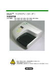
1
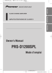
Manual
TTX 300/COBRA Online
Manual
TTX 300 Online
Cobra Online
03/02
Rev. 1.11
1
Manual
TTX 300/COBRA Online
Contents
General notes.......................................................................................................................... 4
Copyright............................................................................................................................... 4
Overview ............................................................................................................................... 4
Setup....................................................................................................................................... 5
Unpacking of printer ............................................................................................................... 5
Setting and connecting of printer............................................................................................. 5
Serial interface connection...................................................................................................... 6
Card slot ............................................................................................................................... 6
Inserting the thermal transfer ribbon........................................................................................ 7
Inserting the label material...................................................................................................... 8
Narrow material web adjustment ............................................................................................. 9
Removal of material and ribbon............................................................................................. 10
Operation .............................................................................................................................. 11
Front panel .......................................................................................................................... 11
Start / connection to computer .............................................................................................. 11
Functions of keys................................................................................................................. 11
Functions of LED elements ................................................................................................... 12
Adjustment of DIP switches .................................................................................................. 12
Adjustment of print head temperature.................................................................................... 13
Maintenance.......................................................................................................................... 14
Overview ............................................................................................................................. 14
Changing and cleaning the print head.................................................................................... 14
Cleaning the feed roller ........................................................................................................ 15
Cleaning the gap sensor....................................................................................................... 15
Cleaning the material and ribbon guides ................................................................................ 15
Tag / Label material ............................................................................................................. 15
Ribbon ................................................................................................................................ 15
Troubleshooting .................................................................................................................... 16
Errors.................................................................................................................................. 16
Status printout ..................................................................................................................... 17
Sensor check routine............................................................................................................ 17
Gap sensor test - ON/OFF key........................................................................................ 18
Head position sensor test - FEED key.............................................................................. 18
Ribbon sensor test - CUT key ......................................................................................... 18
Service .................................................................................................................................. 19
Rear housing ....................................................................................................................... 19
Dismount Mechanics / Electronics from base plate................................................................. 19
Dismount inner, vertical base plate........................................................................................ 20
Remove board ..................................................................................................................... 21
Transformer......................................................................................................................... 21
Power supply (input filter) ..................................................................................................... 22
Fuses of power supply and board.......................................................................................... 22
Gap / Material Sensor .......................................................................................................... 23
Sensor / Ribbon unwinder..................................................................................................... 23
Micro switch / print head pressure lever ................................................................................. 24
Motor, round belt and feed roller ........................................................................................... 24
03/02
Rev. 1.11
2
Manual
TTX 300/COBRA Online
Print head............................................................................................................................ 25
Print head mounting and adjustment ..................................................................................... 25
Head pressure ..................................................................................................................... 26
Ribbon un- and rewind ......................................................................................................... 27
Brake value of ribbon unwind .......................................................................................... 27
Single Start Switch (optional) ................................................................................................ 27
Sensor check routine ............................................................................................................ 28
Gap sensor - ON / OFF key.................................................................................................. 28
Micro switch / print head lever - FEED key............................................................................. 28
Ribbon sensor - CUT key ..................................................................................................... 28
Reflex Sensor (optional) ....................................................................................................... 29
Single Start Switch (optional) ................................................................................................ 29
Factory reset ....................................................................................................................... 29
Appendix ............................................................................................................................... 30
Option: Rewinder ................................................................................................................. 30
Option: Dispenser ................................................................................................................ 31
Dispenser threading detail .................................................................................................... 32
ON/OFF Key - Fonts and Checkerboard Pattern .................................................................... 33
FEED Key - Notched stock test ON/OFF & FEED – Notchless stock test ............................... 34
Bar codes, Lines .................................................................................................................. 35
Technical Specification......................................................................................................... 37
Cable Drawings ................................................................................................................... 39
Internal Cables............................................................................................................... 40
RS232 Interface Cable.................................................................................................... 41
Circuit Diagrams .................................................................................................................. 42
Component Diagram............................................................................................................ 47
Board Layout ....................................................................................................................... 48
Index...................................................................................................................................... 49
03/02
Rev. 1.11
3
Manual
TTX 300/COBRA Online
General notes
Copyright
This User Manual and its contents are subject to copyright. T he publisher’s prior written
consent must be obtained for reproduction of the manual as a whole or part thereof.
Names are generally given without any reference to existing patents, registered patterns or
designs, or trademarks. T he omission of a corresponding note does not imply that the names
can be used freely. All trademarks are acknowledged.
The manufacturer reserves the right to technical and other alterations without prior notice.
The publisher cannot warrant the accuracy of the content of this manual.
Attention : The following sign is used to mark up - that this is an important point !
Note: Please follow the notes shown in this text - it will help to cover all
situations and keep your engine working. .
Overview
The TTX-300 is a feature rich printer offering a wide variety of choices for text, barcode, and
graphic print. T he printer combines quality thermal transfer print with ease of operation in a
space saving package.
To maintain proper performance, use original parts and accessories. T he use of parts not in
compliance with our exacting standards may result in unnecessary problems.
The housing of the unit may only be opened by authorised personnel. Loading of foil, tags,
and labels should be carried out only by trained personnel
Warning: Do not operate the printer with the cover open. Fingers, hair, clothes,
jewellery, etc. may be caught in the printer mechanism.
If the printer will not be used for an extended period of time, relieve pressure on the
printhead by opening the locking lever.
Wait at least 10 seconds after switching the unit “OFF” before switching it back "ON".
Wait at least 60 seconds after switching the printer “OFF” before removing or inserting
PLUG IN CARDS.
Wait at least 3 minutes after switching the printer “OFF” before disconnecting the printhead.
03/02
Rev. 1.11
4
Manual
TTX 300/COBRA Online
Setup
Unpacking of printer
Exercise care when unpacking the printer.
1. Remove top foam packing.
2. Take printer out of cardboard box.
Always carry the printer by the base plate. Never use the front cover, reel holder, or
printhead as carrying handles.
Setting and connecting of printer
Warning: Unplug the printer before checking/changing voltage or fuses!
Check the main voltage setting and fuses. The main voltage setting is visible through a
window in the fuse carrier. If necessary, change the main voltage by removing and turning
the insert. The fuses can be replaced by removing the fuse carrier.
03/02
Rev. 1.11
5
Manual
TTX 300/COBRA Online
Serial interface connection
Caution:
Before connecting or disconnecting the interface cable, switch " OFF"
all dev ices.
A serial interface V.24/DB 25 (RS232) is the standard printer connection.
Card slot
This unit is designed for use with optional font and logo cards.
Cards with maximum of 128 KB may be used.
Caution:
Turn the printer “OFF” and wait at least 60 seconds before
inserting and removing cards. Use only approved cards.
Take care of the card direction (move in).
Card Slot
Dip Switches
Voltage Indicator
Fuse Holder
Locking Tab
Printhead
Temperature
Adjustment
ON / OFF Switch
Power Cord Connector
Communication Interface Connector
03/02
Rev. 1.11
6
Manual
TTX 300/COBRA Online
Ribbon Rewind
Ribbon Supply
Feed Roller
Label Supply
Head Locking Lever
Notch Sensor Adjustment
Material Shaft and Guide (red)
Inserting the thermal transfer ribbon
03/02
Slip a ribbon onto the supply shaft on the right-hand side so that it unwinds in
a counter clockwise direction.
Attach an empty cardboard core onto the rewind shaft on the left-hand side.
Unlock the head by raising the head locking lever.
Thread ribbon as shown. Guide ribbon around rollers and fasten self adhesive
ribbon end counter clockwise at the cardboard core. Tighten the ribbon by
turning the ribbon rewind in a counter clockwise direction.
Rev. 1.11
7
Manual
TTX 300/COBRA Online
Inserting the label material
.
Warning:
Hang label material in label supply reel so that it unwinds in a counter
clockwise direction.
Adjust the red material guide to full width.
Thread the material as shown. T hread past the material guide (red), through
the gap sensor and between printhead and feed roller.
Set the red material guide to the correct width
Position Narrow Web Adjustment according to material width
Close the head locking lever.
Close the cover.
Switch "ON" printer - the Green/Power LED glows.
Press “FEED” to feed material until the ribbon is free of wrinkles. Punched
material feeds one label length each time the “FEED” is pressed. Continuos
material is fed as long as ”FEED” is operated. When using punched or Imark
material, adjust the sensor by moving the metal tab on the Material Shaft until
the tickets feed correctly.
When the cover is open, fingers, hair, clothing, jewellery, etc. may be
caught by the printing mechanism.
head locking lever (red)
in unlocked position
Narrow web adjustment (red)
Ribbon over round bar
ribbon
feed roller
printhead
03/02
Rev. 1.11
8
Manual
TTX 300/COBRA Online
Narrow material web adjustment
Push the Narrow Material Web adjustment IN for narrow material, less than 40mm /
1.575in.
Pull the Narrow Material Web adjustment OUT for wide material, greater than or equal to
40mm / 1.575in.
Note:
Do not adjust the printhead thumbscrews.
Printhead Thumbscrew
Push in for materials less than
40mm / 1.575in.
Pull out for materials greater
than or equal to 40mm /
1.575in.
Red Handle
Printhead Thumbscrew
Narrow Material Web Adjustment - Top View
03/02
Rev. 1.11
9
Manual
TTX 300/COBRA Online
Removal of material and ribbon
Material and ribbon can be removed after opening the head locking lever.
03/02
Rev. 1.11
10
Manual
TTX 300/COBRA Online
Operation
Front panel
The front panel consists of 3 push-button switches and 3 LED’s.
The 3 switches:
ON/OFF
FEED
CUT
The 3 LED’s:
Power - Green
Error - Red
Data - Yellow
Start / connection to computer
Connect interface cable from computer to the printer.
Switch “ON” the printer, the Green/Power LED glows.
Press “ON/OFF”, the printer is switched to "ONLINE mode", the Yellow/Data LED
glows and the printer is ready to receive data and print labels.
Functions of keys
ON / OFF:
Switch to ONLINE or OFFLINE mode. ONLINE mode is indicated by
the Yellow/Data LED, the unit is ready to receive data.
If a print job is interrupted, the Yellow/Data LED flashes rapidly
indicating that a quantity remains. Resume print by pressing the FEED
key.
If an error is indicated (Red/Error LED), the error will be cleared by
pressing “ON/OFF”.
FEED:
In the OFFLINE mode material is advanced. If punched material is
used, one label length is advanced. For continuos material, stock is
fed as long as “FEED” is pressed.
If a print job is interrupted, “FEED” resumes print.
CUT:
03/02
Reserved for optional f unctions.
Rev. 1.11
11
Manual
TTX 300/COBRA Online
Functions of LED elements
The front panel has 3 LED's that indicate the printer’s status.
POWER
green
Power is “ON”
ERROR
red
Error, see “Troubleshooting” section
DATA
yellow
LED glows if printer is “ONLINE”
LED flashes as unit prints, receives data, or builds an image.
LED blinks rapidly if a print job is interrupted. This indicates that
there is a quantity remaining.
LED displays error code with 5 short/long flashes.
Adjustment of DIP switches
Below the interface connection are DIP switches.
Use these switches to adjust the following parameters.
The new DIP switch setting will take effect the next time the printer is turned “ON”.
Switch
Function
1
On = 1 Stop Bit
Select Stop Bits
Switch 2
OFF
ON
OFF
ON
Off = 2 Stop
Bits
Switch 3
OFF
OFF
ON
ON
2-3
4-5
Switch 4
OFF
ON
OFF
ON
Switch 5
OFF
OFF
ON
ON
Baud R ate
19200
9600
4800
2400
6
ON =
XON/XOFF
ON = Online
ON = Direct
T hermal
OFF =
Hardware
OFF = Offline
OFF = T hermal
Transfer
Handshaking Protocol
7
8
Switch position:
03/02
ON
OFF
Select Parity
NONE
SPACE
ODD
EVEN
Power-up Mode
Print Mode
Rev. 1.11
12
Manual
TTX 300/COBRA Online
Adjustment of print head temperature
The printhead temperature can be adjusted by turning the knob located below the interface
connection.
Turning clockwise raises the temperature, turning counter clockwise
lowers it.
Print appearance related to temperature setting
Correct temperature:
Print is sharp and crisp
Low temperature:
Faint print
High temperature:
Smeared print, characters too bold
Extremely high temperature:
Ink particles evaporate, causing faint print.
Printhead is overheated. Damage to
printhead is possible.
minimum
03/02
Rev. 1.11
maximum
13
Manual
TTX 300/COBRA Online
Maintenance
Overview
Careful and regular maintenance will raise the performance and longevity of the printer.
Regular cleaning of the printhead is especially important. A clean printhead ensures high
print quality and extended head life.
Periodically remove any deposits of paper, adhesive and ribbon from the feed roller and gap
sensor.
Changing and cleaning the print head
Warning:
Unplug the printer before cleaning or changing the printhead!
Caution:
Static electricity can destroy electronic components, including the
printhead. Make sure you are properly grounded before servicing
the printer.
Wait at least 3 minutes after switching the printer “OFF” before
disconnecting the printhead.
After changing the print head – the new resistor value has to be
downloaded into the printer (see print head).
Switch unit off and unplug the printer!
Open head locking lever.
Remove material and ribbon.
Unscrew 2 knurled thumbscrews on the printhead holder.
Carefully remove the printhead.
Disconnect printhead plug. Wait at least 3 minutes after switching “OFF” the unit!
Clean print head with dust-free cloth and Avery Dennison cleaning fluid. Metal
objects must never get into contact with printhead surface! Never use knives or o
objects with sharp edges for cleaning. Be aware of static electricity.
Reconnect the printhead plug.
Fasten the printhead using the 2 knurled thumbscrews.
Re-insert the ribbon and labels.
Lower the head locking lever.
03/02
Rev. 1.11
14
Manual
TTX 300/COBRA Online
Cleaning the feed roller
Warning: Unplug the printer before cleaning!
Switch unit OFF and unplug the power cord.
Remove material and ribbon.
Clean print roller with a dust-free cloth and Avery Dennison cleaning fluid. Never
use knives or objects with sharp edges for cleaning.
Cleaning the gap sensor
Use compressed air to clean the gap sensor.
If the sensor is extremely dirty, use a dust-free cloth and Avery Dennison cleaning fluid.
Cleaning the material and ribbon guides
Contaminated surfaces cause poor feeding and reduce print quality. Regularly clean the
material and ribbon guides.
Tag / Label material
The printer may be used for direct thermal and thermal transfer printing.
Use Avery Dennison tags and labels to ensure high quality print.
If the tag/label material is extremely abrasive, the printhead will wear faster than usual.
The width of the ribbon should exceed the width of the tag/label material. T his protects the
printhead from unnecessary wear.
Ribbon
Use Avery Dennison ribbon to ensure high quality print.
IInferior quality ribbons reduce printer performance, print quality, and printhead life.
03/02
Rev. 1.11
15
Manual
TTX 300/COBRA Online
Troubleshooting
Errors
Errors during operation are indicated by the Red/Error front panel LED.
Press the FEED key to display the error code with the Yellow/Data LED.
After the error is corrected, press the ON/OFF key to set the printer back online. After
switching the printer to ONLINE, the job will be continued.
Error Code
Long Flash
Short Flash
Condition
Corrective Action
Head locking lever is raised
End of tag/labels
Ribbon end
NOVRAM read error
NOVRAM write error
No notch/gap found
RS232 - Framing error
RS 232 - Receive Buffer
Overflow
RS232 - Parity
Memory Allocation Error
Font Allocation Error
Unknown Interrupt
Speedo Font Error
03/02
Rev. 1.11
Lower the lever. Press FEED to re
initialise top of form.
Load more tags/labels. Press FEED to
re initialise top of form.
Load more ribbon. Press FEED to re
initialise top of form.
Call service technician
Call service technician
Check that correct material is inserted.
Check that sensor is clean.
Check material guide and position of
sensor.
Check that the label size in the print job
is correct.
Check baud rate, stop bits, and word
length. Correct them at the computer or
printer.
Check handshaking/flow control
Check Parity DIP switch
Call service technician
Call service technician
Call service technician
Call service technician
16
Manual
TTX 300/COBRA Online
Status printout
Status printouts show internal printer fonts, and test patterns. Access the printouts by holding
down different key combinations while switching the power “ON”. Please use material with
width of approximately 100 mm / 4 inches.
Different status print out
STA1
ON / OFF
Fonts and check pattern
STA2
FEED
Version number – dot pattern and a
position
pattern (used for notched media)
STA3
ON/OFF +
Version number – dot pattern and a
position
FEED
pattern (used for notchless media)
To activate:
Press and hold the desired key(s).
While pressing the key(s), switch the power ON.
When the Green/Power LED flashes, release the key(s). T he printer will build the
test image and print the test.
To stop:
Press and hold the ON/OFF key until print stops.
Sensor check routine
Using the keypad and LED’s it is possible to test the operation of the sensors.
There are 3 sensor in the printer:
Gap sensor determines top-of-form and out-of-labels.
Head Position sensor checks if the head is raised or lowered.
Ribbon sensor detects out-of-ribbon.
To access a sensor test:
03/02
Rev. 1.11
17
Manual
TTX 300/COBRA Online
Press and hold the CUT key.
While pressing the CUT key, switch the power ON. T he DATA LED will light.
Release the Cut key.
Press the key required to activate the desired test.
Gap sensor test - ON/OFF key
LED
Status
Green/Power
Air or very translucent backing paper is detected.
Red/Error
Backing paper, liner, or thin paper is detected.
Orange
Cardboard, heavy paper is detected.
Head position sensor test - FEED key
Locking and unlocking the printhead lights the Power or Data LED’s:
Power LED ON:
Head lever locked
Data LED ON:
Head lever unlocked
Ribbon sensor test - CUT key
All LED’s flash as the ribbon supply shaft is rotated.
Note: The ribbon sensor test can also be used to check the operation of the LED’s.
03/02
Rev. 1.11
18
Manual
TTX 300/COBRA Online
Service
Attention: Unplug mains lead before starting any service !
Rear housing
loosen 3 screws (allen key 2.5)
1 pcs upper, left, 2 pcs up (covered half by the disc of material unwinder)
tip housing backwards, bend left side slightly away.
Following the housing may be removed completely backwards
for releasing the cable of the operators panel lift plug 3 mm away from the
board
mounting in reverse order
Connection of cable: Plug in the cable with the contact side forward and press
plug
Dismount Mechanics / Electronics from base plate
This step is necessary when doing services at:
feed roller, material and ribbon guidance, ribbon un- and rewind, print head
pressure axle, printhead fixation and belt
loosen 4 screws at lower side of base plate and remove complete block upwards
03/02
Rev. 1.11
19
Manual
TTX 300/COBRA Online
Dismount inner, vertical base plate
remove pressure lever,
dismount connection of support axle/feed roller
remove print head fixation screws (2 pcs)
remove grounding cable
loosen 4 screws and draw inner base plate backwards
disconnect cables to print head, gap sensor and micro switch (pressure lever)
off the board
remove print head carrier plate complete with square fixation axle (1 screw
from inner side)
remove ribbon end sensor
03/02
Rev. 1.11
20
Manual
TTX 300/COBRA Online
Remove board
For the TTX 300 board with the number 99670-xx-0 are used (different to the OFFLINE
board number 99671-xx-0 the IC’s 13,16,7 and 6 are not placed). Older versions of the
TTX 300 may use different board types.
unplug cables
pull board from the plastic snapper ( 1pcs ), loosen 2 screws from metal angle
and pull up the board
check new board to voltage adjustment
Pin 1
Pin 2
Pin 3
Pin 4
voltage to motor ~ 36 V (not adjustable)
Vcc 5 V (not adjustable)
voltage to print head (adjust with Pot P1 and Pot RV6 to 22V)
GND
Pin 1 Motor ~ 36 V
Pin 2 Vcc 5 V
Pin 3 Kopfsp. 22 V
Masse (Ground)
Transformer
for mounting / dismounting fix the inner metal bolt with a pair of pliers in order to
avoid twisting
03/02
Rev. 1.11
21
Manual
TTX 300/COBRA Online
Power supply (input filter)
before switching on the unit after exchange of the power supply check setting
of
voltage and the corresponding fuses and correct if necessary
Fuses of power supply and board
The fuses can be replaced by removal of the f use element
Mains voltage set up is possible by rotating the insert
Attention :
Unplug mains power plug before checking / changing mains
voltage or fuses.
Power supply
Board
2 x T 2A at 220-240 V
2 x T 4A at 110/115 V
1 x T 10A at bracket
10 AT
03/02
Rev. 1.11
22
Manual
TTX 300/COBRA Online
Gap / Material Sensor
remove complete material guide ( 1 screw inner side)
remove gap / material sensor slide from material guidance
for setting see description of sensor test “CK01”
Sensor / Ribbon unwinder
Accessible after removal of board, twist timing wheel which must not contact sensor.
To check this function see description of sensor check “CK01”.
03/02
Rev. 1.11
23
Manual
TTX 300/COBRA Online
Micro switch / print head pressure lever
Accessible after removal of transformer. Screw micro switch so that the lever can still be
moved 5 –10 mm in direction of closing after the contact has been reached
(clicking noise).
To check this function see sensor check “CK01”.
Motor, round belt and feed roller
Accessible after dismounting the inner, vertical base plate and printhead fixation.
the motors cable guides up and direction forward around the motor and than
below
it. Please regard this routing, otherwise the housing will not fit anymore
between feed roller and motor a gap of 1 mm is necessary
perform status printout “STA4” after mounting a new feed roller
03/02
Rev. 1.11
24
Manual
TTX 300/COBRA Online
Print head
To adjust the optimal print quality the resistance of the print head has to fit with the
adjustments of the board itself.
Action:
Adjust Pot P1 to the maximum (clockwise until block)
Action:
Adjust with Pot RV6 a value of 22 V – measured between Pin 4 (GND)
and Pin 3 (head voltage)
Send the head resistor via Easy Plug command to the printer. T he DATA LED will blink one
time.
#HRn (n 0 resistor of the print head written on the head)
Example:Head resistance - 502 Ohm
#!A1#HR502#G
Attention:To send a wrong value can result in bad print quality or damaging
the head.
To check your work do status print out STA1 after you have changed the print head (or the
board) .
Print head mounting and adjustment
To adjust the print head use the two headless screws at the front of the print head
mounting. The two screws are used to fine adjust the print head to an optimum of print
quality (therefore use the status print out STA1) .
headless screw
knurled screw
headless screw
insert media and ribbon
open the knurled head screws slightly
take care of an optimal media guiding – otherwise the postion grid on the test
label will not be correct
03/02
Rev. 1.11
25
Manual
TTX 300/COBRA Online
start status print out STA1 and adjust with the head less screws the best print out
check your work by using the status print out STA 1 again. The pattern should be
clear on both sides of the print out – as well the angle should be 90 degrees.
finishing the adjustment – secure the headless screws with security paint and fix the
knurled screws again
Head pressure
The adjustment for the head pressure is done by moving the three spring loaded screws
mounted in the axle above the print head spring blades. To adjust the pressure move the
small label device to the outer side (wide media)
To measure the pressure – we are using the friction supplied to a grease free spring blade
(thickness 0.1 mm) and a spring balance of 50 N.
put in grease free backing paper between the spring blade and the print head
to take care not to damage the print head
for the first step move the spring blade to the inner side of the print axle and
adjust a value of 18 – 20 N (value before the blade is starting to move)
second step move the blade to the outer side of the print axle and repeat step
one – but adjust a value of around 16 N only
do status print out STA1 or STA2 to control your work
move the small label device into the inner position and check with STA1 that only
the half of the print is done
03/02
Rev. 1.11
26
Manual
TTX 300/COBRA Online
Ribbon un- and rewind
Accessible after removal of transformer.
put printer side wards before dismounting in order not to loose or jam the shims at
the inner end of the unwinder axle. T his would lead to a leaning position of the
shaft.
Note: There are no shims at the ribbon rewinder
Brake value of ribbon unwind
measured with a cardboard core (wall thickness 3.5 mm) and spring balance 5
N
setting value:
3.6 – 3.8 N (measured in unwind direction)
Single Start Switch (optional)
If the optional single start switch should be used an additional cable must be assembled to
the printer.
Connect the cable to J6 at the main board the other end fits into the hole at the rear side of
the printer (older model of printer may not have this hole at the rear side).
To activate the single start switch send the Easy Plug command #!Dn
n = 0 switch OFF
n = 1 switch ON
03/02
Rev. 1.11
27
Manual
TTX 300/COBRA Online
Sensor check routine
Access to routine
press and keep pressed CUT key for 3 seconds – simultaneously switch on
the unit. T he function is indicated by means of the LED’s. The sensor / switch
can be selected by pressing the corresponding keys.
If the value of the pot (depending to the sensor) is not enough use the pot in
the sensor wires to extend the value.
Gap sensor - ON / OFF key
Adjustment
Adjust with Pot RV3 the sensor connected to J8 in a way that the sensor is sensing
the backing paper (standard) and the red LED is illuminated. Follow this way: turn the
pot until the green LED is illuminated – then turn until the red LED is starting to be
illuminated. Move the pot a little bit of way in the same direction until the red LED is
bright illuminated.
Test
green
red
orange
air or very light backing paper is measured
backing paper or thin paper is measured
card board etc. is measured
Micro switch / print head lever - FEED key
Adjustment
adjust with pot RV5 that the orange LED is illuminated when the lever is open
As soon as the lever is closed, the greed LED is illuminated (the sensor is
connected to J5)
Test
green (closed) or orange (open) are illuminated when opening or closing the
lever
Ribbon sensor - CUT key
Adjustment
adjust with pot RV4 the sensor in a way that all 3 LED’s are illuminated as soon
as the ribbon unwind axle is rotated
Test
when rotating the ribbon mandrel all 3 LED’s become illuminated
03/02
Rev. 1.11
28
Manual
TTX 300/COBRA Online
Reflex Sensor (optional)
Adjustment
Activate the reflex sensor via Easy Plug command #RX n
n = 0 normal punch sensor is used
n = 1 reflex sensor is used
Adjust with pot RV2 a maximum difference (voltage) measured between the two lower
pins (cable color green and black) on connector J7. By using the sensor with white
and black media (paper and black mark).
Test
Test is done by paper feed
Single Start Switch (optional)
Adjustment
not necessary – connected to J 6
Test
use of switch
Factory reset
All parameters are preset ex works to specific values. This factory setting can be reproduced
at any time as follows:
1. Hold the ON/OFF and CUT buttons pressed and switch on the printer.
2. Hold the buttons pressed until all three LEDs start blinking.
3. Release the buttons and switch off the printer.
The Factory reset takes effect after the next powering on.
03/02
Rev. 1.11
29
Manual
TTX 300/COBRA Online
Appendix
Option: Rewinder
The rewind disk has 2 positions: raised and lowered. Make sure the disk is in the
raised position. If necessary, push up on the disk to adjust it.
Insert material according to the following diagram. Fasten the labels to the rewind
using the metal clip.
Remove rewound materials periodically by pulling out the metal clip and sliding the
material off the shaft.
Ribbon
Metal Clip
Label
Rewind Disk
03/02
Rev. 1.11
30
Manual
TTX 300/COBRA Online
Option: Dispenser
Connect the foot pedal to the plug on the back of the printer.
The rewind disk has 2 positions: raised and lowered. Make sure the disk is in the
lowered position. If necessary, push down on the disk to adjust it.
Remove enough labels to expose 1 ft / 40 cm of backing paper.
Thread the liner according to the following diagrams. Tighten liner by rotating the
rewind disk.
Each activation of the foot pedal will dispense one label. One or more blank labels
may dispense before printed labels are available.
Remove rewound liner periodically by pulling out the metal clip and sliding the liner
off the shaft.
Note: By defining the Punch Offset in the label format, the position of the label at the
dispensing edge may be varied. The length defined via Punch Offset must be
regarded as a non-printing area.
Ribbon
Printed
See detail on
following page
Metal Clip
Liner
Foot Switch
03/02
Rev. 1.11
31
Manual
TTX 300/COBRA Online
Dispenser threading detail
Ribbon Over Round Bar
Head Locking Lever
in Unlocked Position
Dispensed Label
Printhead
Liner Over Dispense Bar
Liner Behind this Roller
Ribbon
Label and
Liner Material
Liner Behind and
Under Roller
To Liner
Rewinde
03/02
Rev. 1.11
32
Manual
TTX 300/COBRA Online
ON/OFF Key - Fonts and Checkerboard Pattern
White lines show
bad printhead
elements
03/02
Rev. 1.11
33
Manual
TTX 300/COBRA Online
FEED Key - Notched stock test ON/OFF & FEED –
Notchless stock test
The notched stock test and notchless stock test are very similar. The only difference is that
the notchless stock test does not require a notch to print. The notched stock test does
require a notch, and will not print if no notches are sensed.
Firmware Version Number
Each vertical line represents 1 printhead element (dot).
White gaps indicate failed printhead
This bar is 11mm from the edge. It represents X =10mm.
The bottom of this bar represents the Y =2mm position.
The bottom of this bar represents the Y = 1mm position.
The bottom of this bar represents the Y = 0mm position.
This bar is 6mm in from the edge of ticket. It
represents the X = 5mm position on the ticket.
This bar is 1mm in from the edge of ticket. For notched stock, it rests at the top edge of
the notch. There is always a 1mm inside margin at the edge of the ticket. The bottom
left corner of the bar represents the X = 0mm, Y = 0mm position on the ticket.
03/02
Rev. 1.11
34
Manual
TTX 300/COBRA Online
Bar codes, Lines
03/02
Rev. 1.11
35
Manual
TTX 300/COBRA Online
03/02
Rev. 1.11
36
Manual
TTX 300/COBRA Online
Technical Specification
Print technology
Thermal and Thermal transfer with T hinfilm print head
Resolution
7,56 d/mm – standard
Print width
40 to 105,6 mm
Emulation
Easy Plug
Print speed
100 mm/sec
Interface
Serial Port RS 232
Cards
1 slot for RAM card or PROM card up to 128 KB
Memory
512 KB dynamic RAM
Print ratio
100 % 1:1
Gap recognition
gap dimensions
Self-initialising gap sensor with 0-12 mm variable adjusting
range,
length of punch :
0.8 to 14 mm,
width of punch :
min. 4mm
Reflex marking sensor (only via NISTAN with 2-12 mm variable
adjusting range
Marker length :
4 mm
width :
min 10 mm
Fonts
17 fonts including OCR -A and OCR-B
Character modification
Magnification in X/Y direction up to factor 8
Rotation 90, 180, 270, 360 degree
Barcodes
Barcode Modification
Graphics
Graphic Modification
03/02
EAN 8, EAN 13 with ADD ON 2 and 5, UPC-A, UPC-E,
Code 39, Code 93, Code ITF, Codabar, Code 128,
Code 2/5M, Code 2/5I, Code 2/5 % bar, EAN 128
Magnification in x-direction up to factor 8
in Y-direction from 1 to 100 mm
rotation 90, 180, 270, 360 Grad
Download is supported
Magnification in X/Y direction up to factor 8
Rev. 1.11
37
Manual
TTX 300/COBRA Online
Rotation 90, 180, 270, 360 degree
Material stock
width of media:
Inner roll diameter:
Media Material
Self adhesive, plastics and card boards compatible to
Thermal and Thermal transfer print with a weight of
70 up to 180 gr/sqm and a thickness of 0.05 up to 0.25mm
Label size
width:
110 mm
1.5 “, 2”, 3”, 4”
40 – 110 mm
5 to ~350 mm
length:
Ribbon
Outer diameter:
Electric specification
110, 220, 240 Volt +/- 10% at 48/63 Hz
Power consumption
230 VA
Environmental
Specification
Operating temperature:
Storage temperature:
Humidity:
Noise emission
< 75 dbA
Weight
8,5 kg
Dimensions
Construction
03/02
max. 80 mm
+5 to + 35 degree C
-20 to + 70 degree C
45 to 75% not condensing
245x242x350 mm (WxHxD)
Compact and light weight construction in especially
shielded housing, all mobile axles pivoted, open assembly
of parts and components for easy operating and service
Rev. 1.11
38
Manual
TTX 300/COBRA Online
Cable Drawings
03/02
Rev. 1.11
39
Manual
TTX 300/COBRA Online
Internal Cables
03/02
Rev. 1.11
40
Manual
TTX 300/COBRA Online
RS232 Interface Cable
CN1
CN2
1
6
2
7
3
8
4
9
5
1
6
2
7
3
8
4
9
5
D-SUB BUCHSE 9 POL.
D-SUB STECKER 9 POL.
AVERY Datendruck-Systeme GmbH
Volker Hoefner
Title
TTX 300 Serielles Kabel 9pol auf 9pol
Size
Document Number
B
Date:
03/02
Rev. 1.11
July 31, 1996
REV
98940-00-6
Sheet
1
of
1
41
Manual
TTX 300/COBRA Online
Circuit Diagrams
03/02
Rev. 1.11
42
Manual
TTX 300/COBRA Online
03/02
Rev. 1.11
43
Manual
TTX 300/COBRA Online
03/02
Rev. 1.11
44
Manual
TTX 300/COBRA Online
03/02
Rev. 1.11
45
Manual
TTX 300/COBRA Online
03/02
Rev. 1.11
46
Manual
TTX 300/COBRA Online
Component Diagram
03/02
Rev. 1.11
47
Manual
TTX 300/COBRA Online
J16 offline display
J10 PC keyboard
J12 TPP ext.
J11 floppy power connector
Board Layout
JP 1/ 2 / 5 not used (should be open)
JP 6 step width of stepper (should be open)
JP 7 select kind of RAM - S RAM or PSRAM
SRAM =open
IC 14 real time clock
J5 head switch
J13 online display
Pot RV5 head
IC 6 / 7 / 13 / 16
only if board is used
as OFFLINE
J6 single start
F1 fuse 10 AT
CN1 card connector
JP 5
Pot RV1 single
JP 2
J7 reflex sensor
JP 1
JP 7
J15 floppy data connector
watch P IN 1 at floppy
Pot RV2 reflex
J8 gap sensor
JC 15 only ONLINE
JP 6
Pot RV3 gap
SW1 switch
J9 foil sensor
Poti P1 head voltage fine adjust
J2 test connector:
upside down
PIN 1 – motor ~36V
J14 serial interface
PIN 2 – 5 V logic
J3 stepper motor
J4 printhead data
PIN 3 – head 22V
J17 frame Ground
Pot RV6 head power
03/02
Pot RV4 foil
J1 AC in
Rev. 1.11
48
Manual
TTX 300/COBRA Online
Index
A
F
Adjustment of DIP switches..................12
Adjustment of print head temperature..13
Appendix ...............................................30
Factory reset......................................... 29
FEED ........................8, 11, 16, 18, 28, 34
FEED Key............................................. 34
feed roller........................8, 14, 19, 20, 24
Fonts ............................................... 33, 38
Front panel............................................ 11
Functions of keys.................................. 11
Functions of LED elements .................. 12
Fuses .................................................... 22
Fuses of power supply.......................... 22
B
Barcodes...............................................38
base plate .............................5, 19, 20, 24
C
Cables, internal.....................................41
Card slot..................................................6
Cards.................................................6, 38
Changing and cleaning the print head .14
Character modification..........................38
CK01 ...............................................23, 24
Cleaning the feed roller.........................15
Cleaning the gap sensor.......................15
Cleaning the material and ribbon guides15
Condition...............................................16
Construction..........................................39
Contents..................................................2
Copyright.................................................4
Corrective Action ..................................16
CUT.....................................11, 12, 18, 28
G
Gap / Material Sensor........................... 23
gap dimensions..................................... 38
Gap recognition .................................... 38
Gap sensor test .................................... 18
Graphics................................................ 39
H
Head position sensor test..................... 18
I
input filter .............................................. 22
Inserting the label material ..................... 8
Inserting the thermal transfer ribbon...... 7
Interface Cable ..................................... 42
D
DATA ..............................................12, 18
Diagram.................................................43
Dimension.............................................39
Dismount inner, vertical base plate ......20
Dismount Mechanics ............................19
Dispenser..............................................32
Dispenser threading detail....................32
L
Label size.............................................. 39
M
Maintenance ......................................... 14
Material stock........................................ 39
Media Material ...................................... 39
Memory........................................... 16, 38
Micro switch.................................... 24, 28
Motor..................................................... 24
E
Electric specification.............................39
Emulation..............................................38
Environmental Specification.................39
ERROR .................................................12
Errors ....................................................16
03/02
Rev. 1.11
N
Narrow material web adjustment............ 9
49
Manual
TTX 300/COBRA Online
resolution .............................................. 38
Ribbon.............. 15, 16, 17, 18, 27, 28, 39
Ribbon rewind....................................... 27
Ribbon sensor test................................ 18
Ribbon unwind...................................... 27
round belt.............................................. 24
RS232 Interface Cable ......................... 42
Noise emission .....................................39
Notched stock .......................................34
Notchless stock.....................................34
O
ON/OFF............ 11, 16, 17, 18, 28, 33, 34
Operation ..............................................11
Option
Dispenser .....................................31
rewinder........................................30
Overview...........................................4, 14
S
POWER ................................................12
Power consumption ..............................39
Power supply ........................................22
Print head..............................................25
print head fixation ...........................20, 25
print head pressure lever.....................24
Print ratio...............................................38
Print speed............................................38
Print technology ....................................38
Print width .............................................38
T
Sensor / Ribbon unwinder .................... 23
Sensor check routine...................... 17, 28
Serial interface connection..................... 6
Service.................................................. 19
Setting and connecting of printer ........... 5
Setup....................................................... 5
Start / connection to computer ............. 11
Status print out...................................... 17
P
R
Tag / Label material.............................. 15
Technical Specification......................... 38
Transformer .......................................... 21
Troubleshooting.............................. 12, 16
W
Rear housing.........................................19
Removal of material and ribbon ...........10
Remove board ......................................21
03/02
Rev. 1.11
Weight................................................... 39
Wiring.................................................... 40
50