1
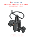
Installation Manual
12x12 Complete Pergola Room
Kit
Revised 04/11/2012
(1.99m)
Customer Support: 1-888-784-0878
(3.37m)
[email protected]
© Quality Edge
2712 Walkent Dr. NW Walker, MI 49544
www.insideoutunderdeck.com
(1.99m)
Height:
8’ 2” or 2.49m
(3.37m)
1
!Important Safety Notice!
•
Components are intended for privacy, decorative and ornamental use only. Product is NOT INTENDED for
the following:
- A safety barrier to prevent unsupervised access to pools, hot tubs, spas, or ponds.
- Safety railings for elevated platforms or decks.
- As load bearing support for a building, structure, heavy objects or swings. - Used in structures that trap
wind, rain or snow that would create extra load on the product.
•
Permanent structures may require a building permit. As the purchaser and or installer of this product you
are advised to consult local planning, zoning, and building inspection departments for guidance on applicable
building codes and or zoning requirements.
•
Wood is NOT flame retardant and will burn. Grills, fire pits and chimneys are a fire hazard if placed too
close to the structure. Consult user’s manual of the grill, fire pit or chimney for safe distances from combustible
materials.
•
During installation, follow all safety warnings provided with your tools and use OHSA approved safety
glasses.
•
Some structures may require two or more people to install safely. Check for underground utilities
before digging or driving stakes into the ground!
General Information: Wood components are manufactured with Cedar (C. Lanceolata) which is protected with
factory applied water-based stain. Knots,
small
(cracks) and
weathering are naturally occurring and do
Keys
tochecks
Assembly
Success
not
affect
the
strength
of
the
product.
Annual
application
of
a
water-based
water repellent sealant or stain will help
Tools Required
reduce weathering and checks.
• Tape Measure
• Carpenters Level
• Carpenters Square
• Claw Hammer
• Standard or Cordless Drill
• Tape Measure
• #1, #2 & #3 Phillips
• Open End Wrench
or Robertson Bits
(7/16”, 1/2” & 9/16”)
or Screwdriver
• Adjustable Wrench
• Ratchet with extension Tools Required
• 1/8” & 3/16” Drill Bits
(1/2” & 9/16” sockets)
• Pencil
• #2 Phillips or Robertson
Bits or Screwdriver
• 3/16” Hex Key
• 8’ Step Ladder
• Safety Glasses
• Adult Helpers
• Safety Glasses
• Adjustable Wrench
Part
Identification
Key
• Carpenters
• 1/8” Drill Bit
Level
On each page, you will find the parts
and
2X A1 Post 2 x 4 x83”
with extension
• Ratchet
• Carpenters
Square
• Pencil
quantities
required
to complete the assembly
(7/16” sockets)
step illustrated on that page. Here is a sample.
• Adult Helpers
• Standard or Cordless
Drill
Symbols
• 3/16” Key
Hex
Key
Number
Part Description, Part Size
• Open End WrenchQuantity
• 8’ Step Ladder
(7/16”)
Throughout these instructions symbols are provided
as
important
reminders
for proper and safe assembly.
Keys To Assemble Success
This identifies information that requires special
attention. Improper assembly could lead to an
unsafe or dangerous condition.
Use
Help
Measure
Distance
Use
Help
Check that set or assembly is properly level
before proceeding.
Pre-drill 1/8” & 3/16” Bit
Where this is shown, 2 or 3
people are required to safely
complete the step. To avoid
injury or damage to the
assembly make sure to get help!
Check that assembly is square
before tightening bolts.
Pre-drill a pilot hole
before fastening screw
or lag to prevent
splitting of wood.
Square
Assembly
Tighten
Bolts
This indicates time to tighten bolts, but
not too tight! Do not crush the wood.
This may create splinters and cause
structural damage.
Use a measuring tape to assure
proper location.
No
CAUTION – Protrusion Hazard
Use
Level
2
Yes
If Bolt protrudes
beyond T-Nut
Material List
A
Nominale
2" x 6"
Normal
2" x 3"
2” x 6”
1" x 6"
Y50113-020
(4) 2 x 6 x 13½"
B
2” x 3”
1” x 6”
Y50113-034
(4) 2 x 6 x 36-13/16"
C
Y50113-036
(4) 2 x 6 x 37"
D
Y50113-037
(4) 2 x 6 x 81Ǭ"
E
Y50113-032
(2) 1 x 6 x 80½"
F
Y50113-022
(4) 2 x 6 x 21ǫ"
G
Y50113-024
(4) 2 x 6 x 80ǩ"
H
I
Y50113-035
(22) 2 x 3 x 34¾"
Y50113-033
(11) 2 x 3 x 83½"
(20) 1/4"
WT
(42) 1/4" x 2"
WL
(22) 1/4"
S1
S2
S3
(44) #10 x 1"
(64) 1/4"
2x3
(8) #8 x 1½"
(22) 2 x 3 (Y70813-001)
(34) #8 x 3½"
2
3
Actuel
1½"
x 5½"
Actual
1½" x 2½"
1 1/2” x 5 1/2”
ǫ" x 5½"
1 1/2” x 2 1/2”
5/8” x 5 1/2”
Post must be securely
installed to support stru
Consult local building
codes and ground con
for required footing des
Material List
R
S4
PX1
S5
B > 24"
S4
S4
(16) Top and Bottom Rail
Cut - Corte - Couper
S4
S7
S7
#8 x 2 1/4” Wood Screw
S7
S5
S5
!
Check for underground
utilities before digging or
driving stakes into the
ground!
¡Verifique
las tuberías
#10laxubicación
1” Pan de
Head
Screw
subterráneas antes de excavar o de
clavar estacas en el suelo!
(8) One High X Topper
S6 S6
S5Vérifiez la présence d'installations de
S6
publics souterraines avant de
S4 services
creuser ou d'enfoncer des piquet dans
le sol!
S7
P
S6
S7
#10 x 1 1/2” Pan Head Screw
#8 x 1 1/2” Wood Screw
4 x 4 Posts a
4 x 4 Postes
4 x 4 Poteau
S5
S6
PX3
4 x 4 Post
4 x 4 con
4 x 4 con
4 x 4 Pos
(12) Post Top Connector With
WH 7/16” Hex Bolt Assembly
(8) Three High X Panel
(12) 4x4 Post
4
(48) Panel Clips
4 x 4 Poste
4 x 4 Potea
tion
n
.
reforzar el ensamblado.
fixations pour panneaux afin de fixer et
de renforcer l'assemblage.
39½"
Assemble Panels
side by side.
Step
Panels
2 1- Assemble
Three Wide
Ancho triple
59
Conecte los paneles lado a lado.
Assemblez les panneaux côte à côte.
1. Remove the upper metal connectors on both sides of PX3 - Three High X Panel. Reattach the metal
Four Wide
Ancho cuádru
connectors to PX3 by securing the bottom two holes of the metal connectors to the top two holes on PX3 so
that the metal connectors stick out from the top. Slide PX1 – One High X Topper between the two protruding
metal connectors on the top of PX3. Attach the metal connectors to the factory drilled holes in PX1.” (Fig. 1A)
*Ensure Panels are oreinted correctly! (Fig. 1B)
2. Secure panels with a S4 - 2 1/4” Wood
Screw the location indicated by the large
R
arrow in the direction of the arrow.
3. Secure R-Top and Bottom Rails to
Note PX1
orientation of keyhole.
Panel Assembly with S4 - 2 1/4” Wood
d reattach
usingInsert
Screws locations
indicated
arrows
in until flush with adjacent panel.
Tenga en cuenta la orientación
male into by
female.
Slide down
del agujero de la cerradura.
n panel.
the direction of the arrow. *R- Top and
Introduzca el extremo macho en el extremo hembra.
Deslícelo
hacia
3. Connect
last assembled
panels to make a fence section.
Bottom Rails will
overhang
1/4”
ondel panel adyacente.
abajo
hasta que quede
al ras
Notez l'orientation de l'encoche
either
side
of
panel.
y vuelva a
Insérez les pièces de raccordement mâles dans les pièces
Instructions en
de trou
basedeserrure.
3 Cut and attach Top and
epeat until
eight
panel
assemblies
are
Pautas
básicas
para
eros 4.de Rraccordement
femelles. Faites glisser le panneau
elniveau
ensamblado
de
created.
Basic
Guidelines
vers
le bas
jusqu'à ce qu'il soit au même
que
for
Panel
Assembly los paneles
le panneau
adjacent.
Las ilustraciones muestran
configuraciones con topes. También
se pueden conectar 2 y 3 paneles
altos
a medida que se adquieran.
Pilot holes to
the right
*Use
los tornillos de acero inoxidable
*Use 2 1/4" stainless steel screws
de
2
1/4"
que se incluyen en el juego
included in the Panel Clip set to
de
sujetadores
de paneles para
secure and strengthen the assembly.
reforzar el ensamblado.
accordement
et using
tors. Shown here are configurations
a Topper. 2 and 3 High Panels can
n des
deux trous
also be connected together as
été
percés à
purchased.
es
2
by side.
Conecte los paneles lado a lado.
Corte
fijewill
los rieles
su
Los rieles
Top and
Bottomy Rail
overhang 1/4"on either side. a cada la
et fixez la en
main
los agc
AttachTaillez
Top with Screws*
through factory drilled holes. inferior, d
One
Wide
Anchotornillos*
sencillo
On Bottom,
space
Screws*
4" from edges of panels.
20"
Two Wide
Ancho doble
39½"
1/4"
Three Wide
Ancho triple
59"
1/4"
Assemblez les panneaux côte à côte.
Screws* are 2 1/4" stainless
steel included in Panel Clip set.
Four Wide
Ancho cuádru
Los tornillos* son de acero inoxidable de 2 1/4"
y se incluyen en el juego de sujetadores de paneles.
}
x8
*Les vis sont celles de 2-1/4 po en acier inoxydable qui sont fournies dans le nécessaire de fixations pour panneaux.
on
s
Les assemblages illustrés comportent des
pièces supérieures. Il est possible
également d'assembler des panneaux
à deux ou à trois carreaux de hauteur
(vendus séparément).
*Utilisez les vis en acier inoxydable de
2-1/4 po fournies dans le nécessaire de
fixations pour panneaux afin de fixer et
de renforcer l'assemblage.
Fig. 1B - Filler Strips on Bottom
of Panel!Panels side
Assemble
les.
dos.
sine.
ors.
pour l'assemblage
des panneaux
4
Fig. 1A
Do not remove Small Connector
PX3
No retire los conectores
Insert male into female. Slide down until flush with adjacent panel.
Ne retirez pas les petites pièces d
Introduzca el extremo macho en el extremo hembra.
Deslícelo
hacia
3. Connect
last assembled
panels to make a
fence section.
raccordement.
abajo hasta que quede al ras del panel adyacente.
Insérez les pièces de raccordement mâles dans les pièces
de raccordement femelles. Faites glisser le panneau
vers le bas jusqu'à ce qu'il soit au même niveau que
le panneau adjacent.
8x
PX1
One High X Topper
8x
PX3
Three High X Panel
16x
R
R
32x
Top & Bottom Rail
5
S4
Top and Bottom Rail will
overhang 1/4"on either side.
#8- 2 1/4” Wood Screws Attach Top with Screws*
through factory drilled holes.
On Bottom, space Screws*
4" from edges of panels.
Los rieles s
a cada lad
en los agu
inferior, de
tornillos* y
Step 2- Attach Panel Clips to posts
1. On a flat surface place P- 4x4 Post
on its side and position Panel Clips in
locations indicated in Figures 1 and
1A. Ensure Panel Clips are oriented
as shown in Diagrams!
Fig. 1
Fig. 1A Side View
Front View
A
B
C
A
2. Panel Clips should be placed in the
centre of the post or the leading edge
of the clip should be 1 3/8” or 3.5cm
away from the side of the post as
shown in Fig. 2.
3. With Panel Clips in place, mark screw
holes with a pencil and pre-drill holes
with a 1/8” drill bit. (Not provided)
4x A
4x B
4x C
4. Secure Panel Clips in locations
indicated in figure 1 and 1A with S7- #8
x 1 1/2” wood screws.
5. Repeat for each post configuration (4
in total).
75”
(190.5cm)
Fig. 2
40”
(101.6cm)
1 3/8”
(3.5cm)
Pre-drill holes and secure with S7- #8 x
1 1/2” Wood Screws
(25.3cm)
Top View
12x
P
4x4 Post
48x - Panel Clips
48x S5 #8 x 1 1/2” Wood Screw
6
Step 3 -Attach Panels to Posts
1. Place panel assemblies on posts as shown (Fig.1) allowing a 4” gap between the bottom of the post and the
bottom edge of the bottom rail on the panel assembly. Assemble with the help of another adult.
2. With a 1/8” drill bit, predrill holes as shown in figure 2.
3. Fasten the panel assembles to the post and Panel Clips with a S5- 1” Pan Head Screw provided in location of
arrows. (Fig. 1)
4. R
epeat until all four pergola bases are assembled.
Fig. 1
x4
Front View
Side View
Fig. 2. Predrill Holes and Fasten
with S5- 1” Pan Head Screw
(10.2cm)
48x
S5
1” Pan Head Screw
7
(10.2cm)
20"
This identifies information that requires special
attention. Improper assembly could lead to an
unsafe or dangerous condition.
Check that set or assembly is properly level
before proceeding.78½"
Step 4- Layout Posts and
Connectors
Use
2
Use
Where this is shown, 2 or 3
1. Layout pergola bases inHelp
configuration
Help shown in figure 1. *Posts must
people are required to safely
be securely installed to support structure. Consult local building
complete the step. To avoid
codes and ground conditions for required
footing
design.
injury
or damage
to theIt is
recommended the structure be secured to
existing
stone,
assembly make sure toconcrete
get help! or
deck with the 4 x 4 Post Base or equivalent hardware.
Measurewith Check
Square
is square
2. Install Post Top Connectors
S6- 1that
1/2”assembly
Pan Head
Screws provided.
Distance
Assembly
before
tightening
bolts.
(Fig. 2) Ensure the direction of the Post Top Connector is the same
direction as indicated by the arrows in figure 1.
Pre-drill 1/8” & 3/16” Bit
Pre-drill a pilot hole
before fastening screw
or lag to prevent
splitting of wood.
This indicates time to tighten bolts, but
not too tight! Do not crush the wood.
This may create splinters and cause
structural damage.
Use a measuring tape to assure
proper location.
No
Once the assembly is tightened, watch for exposed
(199.4cm)
threads. If a thread protrudes from the T-Nut, remove
the bolt and add washers to eliminate this condition.
Extra washers have been provided for this purpose.
Use an extra
Flat Washer
Lag Assembly
Fig. 1
Proper Hardware Assembly
Lag screws require drilling pilot
Lag Screw
Install on a flat
holes to avoid splitting wood. Only
and level surface!
a flat washer is required. For ease of
installation liquid soap can be used
on all lag-type screws.
(199.4cm)
Note: Wafer head bolts with blue lock
tight or a bolt with a Ny-Lok nut do
NOT require a lock washer.
Before mounting
use factory drille
guides to drill 1/8
Flat Washer
Bolt Assembly
Hex Bolt
Lock
Washer
(451.8cm)
Flat
Washer
6
(318.8cm)
48x
S6
Ye
Fig. 2 - Attach Post
Topprotrudes
Connectors
If5 Bolt
with S6- 1 1/2” Pan
Head Screws.
beyond T-Nut
CAUTION – Protrusion Hazard
For bolts, tap T-Nut into hole with
hammer. Insert the hex bolt through
lock washer first then flat washer then
hole. Because the assemblies need to
be squared do not completely tighten
until instructed. Pay close attention to
diameter of the bolts. 5/16” is slightly
larger than 1/4”.
Tig
Bo
1 1/2” Pan head Screws
12x - Post Top Connector
8
T-Nut
(Hammer
Do not c
Assemble 2 DDE Beams. Attach D to D and E to create 2 DDE .
Step 5- Assemble Extended Beam
20X WT
Ensamble 2 vigas (DDE). Una (D) con (D) y (E) para crear 2 (DDE).
Assembler 2 (DDE) Poteau, Fixer (D) a (D) et (E) pour créer 2 (DDE).
2
8X S2
1. Assemble 2 DDE- Extended Beam by securing two D-2 x 6 x 81 7/8” Beams and E-1
x 6 x 80 1/2” Board with WT- Wafer Bolt assembly and S2- #8 x1 1/2” Wood Screws
D 2 DDE Beams. Attach as
Assemble
2 DDE
.
E to create
D toshown.
D and Note:
Wafer
Bolt assembly
in diagram below.
Ensamble 2 vigas (DDE). Una (D) con (D) y (E) para crear 2 (DDE).
20X WT
Assembler 2 (DDE) Poteau, Fixer (D) a (D) et (E) pour créer 2 (DDE).
8X S2
Wafer Bolt Assembly
Wa fer
Bolt
D
T- Nut
Flat
Washer
x2
E
E
WT
WT
X10
X10
D
WT
WT
S2
2
S2
6
20x WT 1/4 x 2” Wafer Bolt Assembly w/ T-Nut
4x
D
2 x 6 x 81 1/2” Beam
8x
2x
E
1 x 6 x 80 1/2” Board
S2
S2
#8- 1 1/2” Wood Screw
6
9
D
3
Attach (4) A (4) C (4) F and (2) DDE . Attach (4) C to (4) D .
12X S3
Una 4 (A) 4 (C) 4 (F) y 2 (DDE). Una 4 (C)con 4 (D).
Attaché 4 (A) 4 (C) 4 (F) et 2 (DDE). Attaché 4 (C) a 4 (D).
Step
Beams
Connectors
Attach Mounting
(4) A (4) C (4) F and
(2) DDE .to
Attach
(4) C to (4) D .
3 6AA
F
12X S3
Una 4 (A) 4 (C) 4 (F) y 2 (DDE). Una 4 (C)con 4 (D).
Attaché 4 (A) 4 (C) 4 (F) et 2 (DDE). Attaché 4 (C) a 4 (D).
F
A
C
F
A
F
C
DDE
A
C
DDE
C
C
C
A
A
F
C
C
F
A
F
A
Fig. 2
1. Attach C to DDE with 3 S3 #8 X 3 1/2”
Wood Screws.
S3
C
2. Attach C to post with 3 WH-Hex Bolts.
Connect the other side to DDE with 3 S3
#8 X 3 1/2” Wood Screws.
D
S3
C
F
3. Attach A to post with 2 WH-Hex Bolts.
Attach F to Post with 2 WH-Hex Bolts,
and the other side to DDE with 2 S3 #8 X
3 1/2” Wood Screws.
D
F
4. Repeat assembly for both beams.
A
A
4x
A
2 x 6 x 13 1/2” Beam End
4x
C
2 x 6 x 37” Beam
12x7S3 #8 x 3 1/2” Wood Screw
56x WH Hex Bolt w/ Nut
7
4x F
2 x 6 x 21 5/8” Beam
10
F
Step 6B- Mounting Beams to Connectors
4
Attach (4) B and (4) G
Una 4 (B) con 4 (G).
Attaché 4 (B) et 4 (G).
B
G
B
G
4
Attach (4) B and (4) G
Una 4 (B) con 4 (G).
Attaché 4 (B) et 4 (G).
B
B
G
B
G
B
G
G
G
G
B
B
1. Connect both DDE panels with 2 G- 2X 6 X 80
1/2 Beams with Hex bolts provided (2 per post
joint).
2. Attach remaining 2 G- 2 X 6 X 80 1/2 Beams
between outside posts (as shown in diagram).
Secure with Hex bolts provided (2 per post).
3. Place 4 B-2 X 6 X 36 13/16” Beams between
A & F and attach to C Beams (as shown in
diagram). Attach with 2 Hex Bolts per post.
4x
E
2 x 6 x 80 1/2” Beams
4x B
2 x 6 x 36 13/16” Beams
8
48x WH Hex Bolt W/ Nuts
118
Step 7- Installing Pergola Roof
5
Attach (22) H and (11) I .
Una 22 (H) con 11 (I).
Attaché 22 (H) et 11 (I).
Wa fer
Bolt
Fig. 2
Wa fer Bolt Assembl
22Xy S3
T- Nut
44X S1
Flat
Washer
5
22X WL
Attach (22) H and (11) I .
Una 22 (H) con 11 (I).
Attaché 22 (H) et 11 (I).
22X S3
22X
2x3
44X S1
22X WL
22X
S1
2x3
S1
Fig. 1
1. Assemble roof by fastening H-2
x 3 x 34 3/5” Trellis Ends to I-2 x
3 x 83 1/2” Trellis Middle using 2x3- Metal Bracket and WLWafer bolts as shown in Fig. 1
WL
WL
S3
H
X22
I
x11
IX11
Fig. 3
3. Allow for a 10 1/4” or 26cm
gap between each trellis
assembly and 4 1/4” or 11cm
gap between the outside trellis
assemblies and the outside
beam side. Fig. 3.
4. Fasten roof to beams with
S3- #8 x 3 1/2” Wood Screw at
pre-drilled hole 10¼"
on trellis end
and S1- #10 x 1” Pan Screw on
2x3-Metal Bracket.
2x3
I
2. Layout the roof on the beams
as shown in figure 2.
S3
H
X22
X22
X22
WL
10¼"
(26cm)
WL
(11cm)
4¼"
4¼"
22x
H
2 x 3 x 34 3/4” Trellis End
22x
11x
I
2 x 3 x 83 1/2” Trellis Middle
44x S1 #10 x 1” Screw
S3
#8 x 3 1/2” Wood Screws
22x - 2x3 Bracket
9
12
9
2x3
22x
WL 1/4 x 2” Wafer Bolt Assembly
w/ Nut
X11