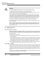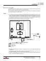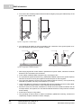
1
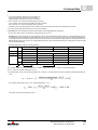
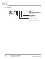
Mono Power Unit BUM 60-30 / BUM 60-31 Manual E 5.01031.02a Title Manual Product Mono Power Unit BUM 60-30 / BUM 60-31 Version 5.01031.02a Status 2004-07-12 Copyright These operating instructions may be copied by the owner in any quantity but only for internal use. For other purposes these operating instructions and extracts thereof must not be copied or reproduced. Use and disclosure of information contained in these operating instructions are not permitted. Designations and company marks contained in these operating instructions may be brand names, the use of which by third parties for their own purposes may violate the rights of the holders. Obligatory These operating instructions are part of the equipment/machine. These operating instructions must be available to the operator at all times and must be in a legible condition. If the equipment/machine is sold or moved to a different location these operating instructions must be passed on by the owner together with the equipment/machine. After any sale of the equipment/machine this original and all copies must be handed over to the buyer. After disposal or any other end of use this original and all copies must be destroyed. When the present operating instructions are handed over, corresponding sets of operating instructions of a previous version are automatically invalidated. Please notice that specifications/ data/information are current values according to the printing date. These statements are not legally binding according to the measurement, computation and calculations. Baumüller Nürnberg GmbH reserves the right, in developing its products further, to change the technical specifications and the handling of the products concerned without prior notice. No liability can be accepted concerning the correctness of the operating instructions unless otherwise specified in the General Conditions of Sale and Delivery. Manufacturer Baumüller Nürnberg GmbH Ostendstr. 80 - 90 D-90482 Nürnberg Germany Tel. +49 9 11 54 32 - 0 Fax: +49 9 11 54 32 - 1 30 www.baumueller.de Table of Contents 1 Safety Notes . . . . . . . . . . . . . . . . . . . . . . . . . . . . . . . . . . . . . . . . . . . . . . . . . . . . . . . . . . . . . 5 Qualified personnel . . . . . . . . . . . . . . . . . . . . . . . . . . . . . . . . . . . . . . . . . . . . . . . . . . . . Application as directed . . . . . . . . . . . . . . . . . . . . . . . . . . . . . . . . . . . . . . . . . . . . . . . . . Voltage test . . . . . . . . . . . . . . . . . . . . . . . . . . . . . . . . . . . . . . . . . . . . . . . . . . . . . . . . . . 6 7 7 Introduction . . . . . . . . . . . . . . . . . . . . . . . . . . . . . . . . . . . . . . . . . . . . . . . . . . . . . . . . . . . . . . 9 1.1 1.2 1.3 2 2.1 2.1.1 2.1.2 General . . . . . . . . . . . . . . . . . . . . . . . . . . . . . . . . . . . . . . . . . . . . . . . . . . . . . . . . . . . . . 9 Description of function . . . . . . . . . . . . . . . . . . . . . . . . . . . . . . . . . . . . . . . . . . . . . . . . 9 Block diagram. . . . . . . . . . . . . . . . . . . . . . . . . . . . . . . . . . . . . . . . . . . . . . . . . . . . . . 10 3 Transportation, Unpacking . . . . . . . . . . . . . . . . . . . . . . . . . . . . . . . . . . . . . . . . . . . . . . . . 4 Assembly . . . . . . . . . . . . . . . . . . . . . . . . . . . . . . . . . . . . . . . . . . . . . . . . . . . . . . . . . . . . . . . 13 Dimensions [mm] . . . . . . . . . . . . . . . . . . . . . . . . . . . . . . . . . . . . . . . . . . . . . . . . . . . . Assembly information . . . . . . . . . . . . . . . . . . . . . . . . . . . . . . . . . . . . . . . . . . . . . . . . . 14 14 Installation . . . . . . . . . . . . . . . . . . . . . . . . . . . . . . . . . . . . . . . . . . . . . . . . . . . . . . . . . . . . . . 17 4.1 4.2 5 5.1 5.2 5.3 5.4 5.5 5.5.1 5.5.2 5.6 6 11 Danger information . . . . . . . . . . . . . . . . . . . . . . . . . . . . . . . . . . . . . . . . . . . . . . . . . . . EMC information . . . . . . . . . . . . . . . . . . . . . . . . . . . . . . . . . . . . . . . . . . . . . . . . . . . . . Connection diagram . . . . . . . . . . . . . . . . . . . . . . . . . . . . . . . . . . . . . . . . . . . . . . . . . . Connection information . . . . . . . . . . . . . . . . . . . . . . . . . . . . . . . . . . . . . . . . . . . . . . . . Pin assignments . . . . . . . . . . . . . . . . . . . . . . . . . . . . . . . . . . . . . . . . . . . . . . . . . . . . . Power terminals . . . . . . . . . . . . . . . . . . . . . . . . . . . . . . . . . . . . . . . . . . . . . . . . . . . . Control terminals . . . . . . . . . . . . . . . . . . . . . . . . . . . . . . . . . . . . . . . . . . . . . . . . . . . Accessories . . . . . . . . . . . . . . . . . . . . . . . . . . . . . . . . . . . . . . . . . . . . . . . . . . . . . . . . 17 18 25 26 28 28 29 29 Commissioning . . . . . . . . . . . . . . . . . . . . . . . . . . . . . . . . . . . . . . . . . . . . . . . . . . . . . . . . . . 31 6.1 6.2 6.3 6.3.1 6.3.2 Danger information . . . . . . . . . . . . . . . . . . . . . . . . . . . . . . . . . . . . . . . . . . . . . . . . . . . Operation . . . . . . . . . . . . . . . . . . . . . . . . . . . . . . . . . . . . . . . . . . . . . . . . . . . . . . . . . . Messages and warnings . . . . . . . . . . . . . . . . . . . . . . . . . . . . . . . . . . . . . . . . . . . . . . . Monitoring facilities of the feed current converter. . . . . . . . . . . . . . . . . . . . . . . . . . . Monitoring facilities on motor-end inverter . . . . . . . . . . . . . . . . . . . . . . . . . . . . . . . 31 33 33 33 34 Maintenance . . . . . . . . . . . . . . . . . . . . . . . . . . . . . . . . . . . . . . . . . . . . . . . . . . . . . . . . . . . . 37 Maintenance information . . . . . . . . . . . . . . . . . . . . . . . . . . . . . . . . . . . . . . . . . . . . . . Environmental conditions . . . . . . . . . . . . . . . . . . . . . . . . . . . . . . . . . . . . . . . . . . . . . . Recommissioning . . . . . . . . . . . . . . . . . . . . . . . . . . . . . . . . . . . . . . . . . . . . . . . . . . . . Disposal . . . . . . . . . . . . . . . . . . . . . . . . . . . . . . . . . . . . . . . . . . . . . . . . . . . . . . . . . . . 37 38 38 39 Appendix A - Abbreviations . . . . . . . . . . . . . . . . . . . . . . . . . . . . . . . . . . . . . . . . . . . . . . . . . . 41 Appendix B - Technical Data . . . . . . . . . . . . . . . . . . . . . . . . . . . . . . . . . . . . . . . . . . . . . . . . . 43 B.1 B.2 B.3 B.4 43 44 44 46 7 7.1 7.2 7.3 7.4 Environmental requirements . . . . . . . . . . . . . . . . . . . . . . . . . . . . . . . . . . . . . . . . . . . Mechanical Data . . . . . . . . . . . . . . . . . . . . . . . . . . . . . . . . . . . . . . . . . . . . . . . . . . . . . Electrical Data. . . . . . . . . . . . . . . . . . . . . . . . . . . . . . . . . . . . . . . . . . . . . . . . . . . . . . . Type Code . . . . . . . . . . . . . . . . . . . . . . . . . . . . . . . . . . . . . . . . . . . . . . . . . . . . . . . . . Manual BUM 60-30 / BUM 60-31 Document-No.: 5.01031.02a 3 of 54 Table of contents Appendix C - Declaration of Conformity / by Manufacturer . . . . . . . . . . . . . . . . . . . . . . . . . 47 C.1 C.2 C.3 C.4 C.5 C.6 What is an EU directive? . . . . . . . . . . . . . . . . . . . . . . . . . . . . . . . . . . . . . . . . . . . . . . . What the CE symbol indicates . . . . . . . . . . . . . . . . . . . . . . . . . . . . . . . . . . . . . . . . . . . Definition of the term Declaration of Conformity. . . . . . . . . . . . . . . . . . . . . . . . . . . . . . Definition of the term Declaration by Manufacturer . . . . . . . . . . . . . . . . . . . . . . . . . . . Declaration of conformity . . . . . . . . . . . . . . . . . . . . . . . . . . . . . . . . . . . . . . . . . . . . . . . Declaration by manufacturer . . . . . . . . . . . . . . . . . . . . . . . . . . . . . . . . . . . . . . . . . . . . 47 47 48 48 49 50 Index . . . . . . . . . . . . . . . . . . . . . . . . . . . . . . . . . . . . . . . . . . . . . . . . . . . . . . . . . . . . . . . . . . . . . . 51 Table of figures . . . . . . . . . . . . . . . . . . . . . . . . . . . . . . . . . . . . . . . . . . . . . . . . . . . . . . . . . . . . . . 53 4 Manual BUM 60-30 / BUM 60-31 of 54 Document-No.: 5.01031.02a Baumüller Nürnberg GmbH SAFETY NOTES 1 Preliminary remarks During operation, the principles on which the converter and motor work, lead to leakage currents to earth which are dissipated via specified protective earth connections and which may result in a current-operated e.l.c.b. on the input side blowing prematurely. A DC component in the fault current may occur in the event of a short-circuit to frame or earth fault which makes a triggering of the higher-level current-operated e.l.c.b. more difficult or even impossible. The connection of the current controller to the mains using only the current-operated e.l.c.b. is prohibited (standard EN 50178 / VDE 0160 /4.98, sections 5.2.11 and 5.3.2.1) The units are protected against direct contact by being installed into common switching cabinets which meet the minimum protection requirements according to EN 50178 / VDE 0160 / 4.98, section 5.2.4. The protective measures and safety regulations according to DIN/VDE are binding for personal security. Neglecting to fit PE connections on the unit or the motor will result in serious personal injury and/ or considerable damage to material assets. General information These operating instructions contain all the information necessary for correct operation of the products described. The document is intended for specially trained, technically qualified personnel who are well-versed in all warnings and commissioning activities. The unit is manufactured using state-of-the-art technology and is safe in operation. It can safely be installed and commissioned and functions without problems if the information in this documentation is followed. WARNING The following may occur if you do not observe the danger information given: f considerable damage to material assets f severe personal injury f death When operating electrical equipment, some parts of the equipment always carry dangerous voltages. Only qualified personnel who are familiar with the safety information, assembly, operation and maintenance instructions may carry out work on this equipment. Manual BUM 60-30 / BUM 60-31 Document-No.: 5.01031.02a 5 of 54 1.1 Qualified personnel Danger information On the one hand, the information below is for your own personal safety and on the other to prevent damage to the described products or to other connected equipment. In the context of the operating instructions and the information on the products themselves, the terms used have the following meanings: DANGER The following will occur if you do not observe the danger information given: f considerable damage to material assets f severe personal injury f death WARNING The following may occur if you do not observe the danger information given: f considerable damage to material assets f severe personal injury f death NOTE This note is very important information. 1.1 Qualified personnel Qualified personnel in the sense of the safety-relevant information in this document or on the products themselves, are considered to be persons who are familiar with setting up, assembling, commissioning and operating the product and who have qualifications appropriate to their activities. f Trained or instructed or authorised to commission, ground and mark circuits and equipment in accordance with recognised safety standards. f Trained or instructed in accordance with recognised safety standards in the care and use of appropriate safety equipment. 6 Manual BUM 60-30 / BUM 60-31 of 54 Document-No.: 5.01031.02a Baumüller Nürnberg GmbH Safety Notes 1.2 1 Application as directed WARNING You may only use the unit/system for the purposes specified in the operating instructions and in conjunction with the third-party equipment and components recommended or authorised by Baumüller Nürnberg GmbH. For safety reasons, you must not change or add components on/to the unit. The operator must report immediately any changes that occur which adversely affect the safety of the unit/system. 1.3 Voltage test Baumüller Nürnberg GmbH carries out a voltage test according to EN 50178 / VDE 0160 /4.98, Section 9.4.5 for each unit. Subsequent high-voltage tests must only be carried out by Baumüller Nürnberg GmbH. WARNING If you want to carry out high-voltage tests for complete switch cabinet installations, disconnect all cables from Baumüller units prior to the test. Manual BUM 60-30 / BUM 60-31 Document-No.: 5.01031.02a 7 of 54 8 Manual BUM 60-30 / BUM 60-31 of 54 Document-No.: 5.01031.02a Baumüller Nürnberg GmbH INTRODUCTION 2 2.1 General The mono power unit BUM 60 complements the Baumüller Modular System in the medium performance range. Plug-in analog controller cards are supposed to be used for closed-loop control. NOTE The controller is fitted as plug-in card and the description, which is available separately, contains the respective properties and technical data. The mono power unit BUM 60 consists of the feed current converter on the mains side and the motor-end inverter. 2.1.1 Description of function The whole unit BUM 60 consists of the three parts feed current converter on the mains side, motor-end inverter and controller plug-in card. This documentation does not refer to the available controllers. Each controller comes with its own documentation. f Feed current converter on the mains side The feed current converter is an non-controllable B6 rectifier with starting current load relief and ballast circuit. f Starting current load relief Because of the intermediate circuit capacity without starting current load relief, a direct switch-on of the unit would lead to an inadmissibly high level of impulse current. To avoid this impulse current, the starting current is limited by a resistor. f Ballast circuit In certain operation modes feeds the motor energy to the unit. This energy is stored and leads to a higher intermediate circuit voltage. To avoid reaching the over voltage switch-off threshold, the feed-back energy is transformed to heat in an internal or external ballast resistor. f Motor-end inverter The motor-end inverter comprises the IGBT power unit and the accompanying detectors. The detectors supply on the one hand measurement signals and on the other hand the self-protection facilities of the power electronic. The control of the inverter is run by the controller. Manual BUM 60-30 / BUM 60-31 Document-No.: 5.01031.02a 9 of 54 2.1 General With this power module - in connection with units, containing feed current converters - multi axle systems can be built, that enable a power transfer via the intermediate circuit. 2.1.2 Block diagram Illustration 1: BUM 60-30/BUM 60-31 - 0000 10 Manual BUM 60-30 / BUM 60-31 of 54 Document-No.: 5.01031.02a Baumüller Nürnberg GmbH TRANSPORTATION, UNPACKING 3 The units are packed at the factory in accordance with the order. h You should avoid jolting or dropping the package in transit, e.g. when putting the unit down. You can start assembly after unpacking the equipment and checking that it is complete and undamaged . The equipment is packed in cardboard, corrugated sheeting and/or wooden packaging that you should dispose of in accordance with local regulations. h Report any damage that has occurred in transit immediately. DANGER The following will occur if you do not observe the danger information given: f considerable damage to material assets f severe personal injury f death If the unit was damaged in transit, a qualified person must check, repair and test it before it may be connected. Manual BUM 60-30 / BUM 60-31 Document-No.: 5.01031.02a 11 of 54 12 Manual BUM 60-30 / BUM 60-31 of 54 Document-No.: 5.01031.02a Baumüller Nürnberg GmbH ASSEMBLY 4 WARNING The following may occur if you do not observe the danger information given: f considerable damage to material assets f severe personal injury f death The user is responsible for the assembly of the unit described, the motor, and the other devices according to the safety regulations (e.g. EN, DIN, VDE) and all other relevant national or local regulations concerning the conductor ratings and protection, grounding, disconnectors, overcurrent protection, etc. Ensure that there is no blockage of cooling air flowing into and out of the unit and that there is enough space above and below the equipment to prevent overheating. Manual BUM 60-30 / BUM 60-31 Document-No.: 5.01031.02a 13 of 54 4.1 Dimensions [mm] 4.1 Dimensions [mm] 4.2 Assembly information WARNING The following may occur if you do not observe the danger information given: f considerable damage to material assets f severe personal injury f death Lifting incorrectly can result in personal injury or damage to property. The device should only be lifted by appropriately qualified personnel using the proper equipment. h Install the units vertically in a switching cabinet. If there are several units, mount them next to one another. WARNING The following may occur if you do not observe the danger information given: f considerable damage to material assets f severe personal injury f death It is crucial to comply with the ventilation measures listed below. Ignoring these measures can lead to the unit overheating. h Ventilation must be from the bottom to the top. h Ensure that the flow of air is not restricted. h Ensure that there is a minimum clearance of at least 50 mm above and below the unit and ensure that there is enough cooling air that can circulate freely! 14 Manual BUM 60-30 / BUM 60-31 of 54 Document-No.: 5.01031.02a Baumüller Nürnberg GmbH Assembly 4 h The temperature of the coolant 50 mm below the devices may be up to 40° C. At higher temperatures (up to a maximum of 55° C), reduce the power of the devices by 3 % per degree Celsius. h Do not locate any additional sources of heat above or below the devices. h Avoid degrees of contamination 3 and 4 according to standard EN 50178:4.98 Section 5.2.15.2. The devices are suitable for use in enclosed workshops (VDE 0558 Part 1a, Sections 5.4.3.2.1 and 5.4.3.2.2). DANGER The following will occur if you do not observe the danger information given: f considerable damage to material assets f severe personal injury f death The live parts take more than one minute to discharge. Manual BUM 60-30 / BUM 60-31 Document-No.: 5.01031.02a 15 of 54 16 Manual BUM 60-30 / BUM 60-31 of 54 Document-No.: 5.01031.02a Baumüller Nürnberg GmbH INSTALLATION 5 5.1 Danger information WARNING The following may occur if you do not observe the danger information given: f considerable damage to material assets f severe personal injury f death This device carries dangerous voltage and contains dangerous rotating parts (fans). The user is responsible for the assembly of the converter, the motor, the mains choke and the other devices according to the safety regulations (e.g. DIN, VDE) and all other relevant national or local regulations concerning the conductor ratings and protection, grounding, disconnectors, overcurrent protection, etc. The protective measures and safety regulations according to DIN/VDE are binding for personal security. If there are no PE connections on the unit, the commutation choke or the motor, personal injury may be caused since the surface may carry hazardous voltage. During operation, the principles on which the unit and motor work, lead to leakage currents to earth which are dissipated via specified protective earth connections and which may result in a current-operated e.l.c.b. on the input side blowing prematurely. A DC component in the fault current may occur in the event of a short-circuit to frame or earth fault which makes a triggering of the higher-level current-operated e.l.c.b. more difficult or even impossible. Make the PE connection according to DIN EN 60204 / VDE 0113 Part 1 / 1997, Section 8.2.2. considering EN 50178 / VDE 0160/4.98, Sections 5.3.2.1 and 8.3.4.4. When an error occurs, the drive is de-energised and the motor coasts to stop. This fact must be taken into account particularly for hoist and lifting drives. Prior to connecting the drive, carefully check all higher-level safety equipment for perfect functioning, to avoid personal injury. Malfunction of the drive During the initial commissioning, a faulty or uncontrolled movement of the driven machine elements cannot be excluded. Therefore, proceed with particular care. Manual BUM 60-30 / BUM 60-31 Document-No.: 5.01031.02a 17 of 54 5.2 EMC information WARNING The following may occur if you do not observe the danger information given: f considerable damage to material assets f severe personal injury f death Protection against contact according to Paragraph 4 Section 4 VBG 4 Protection against direct contact comprises all measures against danger which can result from touching the active parts of electrical equipment. Switch cabinet must have emergency stop facilities using which all voltages causing dangerous situations, can be switched off. This does not include equipment which, if switched off, would cause another dangerous situation. The releasing element for the emergency stop facility must be arranged such that it can easily be reached in case of danger. In the event of work which is considerably more dangerous that usual, another person must be present. The operator must ensure that unauthorised persons do not work on the machine. The operator must report immediately any changes that occur which adversely affect the safety of the unit/system. Before dismantling safety equipment during commissioning, repair and maintenance, ensure that the machine is taken out of commission in accordance with applicable regulations. Remount and check the safety equipment immediately after completing commissioning, repair and maintenance work. 5.2 EMC information General information on converters Baumüller converters are equipped with IGBTs. The power loss in the converter is minimized by fast switching operation of the IGBTs. The size of the power modules is thus decreased. The fast switching operation of the IGBTs causes electromagnetic influences, which may influence other components. Interferences may be caused by: f capacitive fault currents. This is caused by high voltage peaks and switching of bipolar transistors and IGBTs. f high currents and current peaks in the motor cables. The interfering energy bound in magnetic fields reaches frequencies of a few Hertz up to approx. 30 MHz. Due to the high voltage peaks, additional electromagnetic fields occur with frequencies of up to approx. 600 MHz. f high chopping rates and fast logic circuits (electromagnetic field with 16 MHz…1 GHz). f Mains feedbacks and harmonics. These are caused by commutations and non-sinusoidal mains loading, particularly for mains-commutated controllers (100 Hz ... 20kHz). German EMC Law (EMVG) This converter corresponds to § 6 Section 9 of EMVG (German EMC Law) dated 18 Sept. 1998. "Devices, systems and components according to section 3 which are exclusively manufactured or stocked as vendor parts or spare parts for further processing by industrial companies or craftsmen with proficient knowledge of in the field of electromagnetic compatibility do not have to comply neither with the safety standards nor with the demands of § 4 Section. 1 No. 1 to 3 and 5. This takes into account that EMC is essentially dependent on the subassemblies of the individual modules and components in the switch cabinet. 18 Manual BUM 60-30 / BUM 60-31 of 54 Document-No.: 5.01031.02a Baumüller Nürnberg GmbH Installation 5 Measures for ensuring EMC To minimize the electromagnetic influences mentioned above, certain requirements have to be fulfilled for cabling, grounding, screening and filter assembly. The information on the next pages is intended to help you to plan the installation according to the latest knowledge in the field of EMC. Cabling f To suppress noise emission outside the converter always screen all connected cables. If the switch cabinet has a sufficient screening attenuation (see limit value for suppression of interference according to EMVG for the installation planned) and the compatibility is guaranteed inside the switch cabinet (you can make this assumption when all configuring aids given in this chapter are observed) the control lines can be mounted unshielded. Also observe the items in Section ZScreening– from page 22. Figure 2: Cabling unit f You may presume that limit values are complied with only if you use Baumüller cables and components. f The maximum length of the cable is limited. The maximum length depends on the cross section of the cable (e.g. 100 m for 1,5 mm2, 30 m for 35 mm2). f The motor cable between power unit and motor has to be in one piece. Do not break the cable by e.g. terminals, contactors, fuses etc. Manual BUM 60-30 / BUM 60-31 Document-No.: 5.01031.02a 19 of 54 5.2 EMC information f You achieve the smallest possible effective antenna height by laying the cable directly on the ground of the metallic rack. Figure 3: Laying cable - antenna height f You should lay all cables as close as possible to the conductors of the ground system to reduce the effective loop area for magnetic coupling. Figure 4: Laying cable - effective loop area f When laying signal and control cables in parallel across power cables, maintain a minimum distance of 20 cm between the conductors. f Cross cables of different EMC categories only at an angle of 90°. f For symmetrical signal transmission (e.g. differential amplifier inputs for the speed setpoint), twist the conductors of each pair together and twist the pairs of wires together. f The connection between converter and ground plate should be as short (< 30 cm) and finely stranded as possible. Use large cross-sections (> 10 mm2) f connect the filters PE connection on the load side with low impedance to the mounting plate. Using a galvanized angle metal or a RF earthing strip would be ideal. f Sources of noise such as fuses, transformers, chokes and noise-sensitive modules such as microprocessors, bus systems, etc. should be located at least 20 cm away from the converter and its cabling. f Avoid reserve loops on long cables. f The grounding of reserve wires in cables is mandatory (additional screening, avoidance of capacitively coupled, hazardous contact voltages). 20 Manual BUM 60-30 / BUM 60-31 of 54 Document-No.: 5.01031.02a Baumüller Nürnberg GmbH Installation 5 f Do not connect mains filters in parallel. f Do not connect identical mains filters in series - the attenuation response will not improve. f Do suppress every mono power unit individually. If it is absolutely necessary to suppress all units collectively - do not break any of the shields between units and mains filter. That is that shielded cables may not be broken by fuses, shunts or other components. Grounding f The classical star grounding is no longer sufficient to reduce the noise of high frequencies caused by converter operation. Better results can be achieved by a reference surface which must be linked to the units’ ground (e.g. bare metal mounting plate and housing parts) covering an large area. f Apply all ground connectors and screens as close as possible above the ground to avoid earth loops. f If it is possible to ground the controller reference potential of the power unit, make the connection with as large a cross-section as possible and a short cable (< 30 cm). f Remove insulating layers such as paint, adhesives, etc. from the ground connections. If necessary, use serrated lock washers (DIN 6798) to penetrate the surface and thereby ensure a permanent, conductive contact. To prevent corrosion on ground connections, use suitable metal combinations (electrochemical series of metals) and keep conductive electrolytes away from the connection by a protective coating (e.g. grease). f Always connect screens at both ends over a large surface and conductive to ground. This is the only way to suppress the effects of magnetic or high-frequent noise. If earth loops occur (e.g. double insulation of the setpoint conductor screen), apply the receiver side galvanically and the transmitter side capacitively. f When laying external cable screens through panels separating different EMC areas, make contact to the cable screens. Cables which are passed through the panels of screening housings without special measures (e.g. filtering), may impair the screening effect of these housings. For this reason, you must make a conductive connection of the cable screens at the point at which the cable enters the housing. The distance of the last screen contact point to the exit of the cabinet must be as short as possible. Figure 5: Laying cable - exit of the cabinet Manual BUM 60-30 / BUM 60-31 Document-No.: 5.01031.02a 21 of 54 5.2 EMC information Screening f The screen is effective against magnetic fields when it is connected to ground at both ends. With electrical fields, the screening is effective if the screen is connected to ground at one end. Fields with high frequencies (depending on the cable length) always are electromagnetic fields. It is not of importance if the field is electrical or magnetic - always apply the screen at both ends. Figure 6: Laying cable - apply the screen If you apply the screen to ground at both ends, the cable does not leave the screening ”system housing”. f Even if you connect cable screens to ground at both ends, the effect of earth loops (potential difference on the ground system) cannot be totally excluded. However, these are very rare if you observe the measures of the chapters ZCabling– from page 19 and ZGrounding– from page 21. The HF connection of a screen to ground can also be capacitive. This prevents low-frequent noise caused by earth loops. Screen cables passing through different EMC areas must not be separated at the terminals, otherwise the screening would be reduced considerably. They should be led to the next module without interruption. The screen connection must be of low impedance and over a large surface. Cable tails with a length of only 3 cm (1 cm wire = 10 nH) reduce the screening of up to 30 dB when noise occur in the MHz range! NOTE The screen braid must have a coverage of at least 85 %. The following cables have a particularly high interference potential: f Motor cable f Cable to external regenerative resistors f Cable between mains filter and converter (if longer than 30 cm) 22 Manual BUM 60-30 / BUM 60-31 of 54 Document-No.: 5.01031.02a Baumüller Nürnberg GmbH Installation 5 Figure 7: Proposal for the screen connection Manual BUM 60-30 / BUM 60-31 Document-No.: 5.01031.02a 23 of 54 5.2 EMC information cable diameter ∅ (mm) Article no. 2 x 2 - 6 mm 226752 3 - 8 mm 226741 4 - 13,5 mm 226745 10 - 20 mm 226749 larger diameters on request Figure 8: Screen terminals for grounding 24 Manual BUM 60-30 / BUM 60-31 of 54 Document-No.: 5.01031.02a Baumüller Nürnberg GmbH Installation 5.3 5 Connection diagram 1) option only for BUM 60 - 30/60 - 31 - B - 2) When using an external ballast resistor, remove wire bridge between RBint and BA- and connect the external ballast resistor to X1:2 and X1:4 If UL508C has to be observed: the external ballast resistor must protect itself from overheating Manual BUM 60-30 / BUM 60-31 Document-No.: 5.01031.02a 25 of 54 5.4 5.4 Connection information Connection information Closed-loop controller Refer to separate controller descriptions K1 Main contactor with auxiliary contact for controller enable DANGER The following will occur if you do not observe the danger information given: f considerable damage to material assets f severe personal injury f death A controller enable on the controller may not be issued until the intermediate circuit capacitors have been completely charged, i.e. 1 sec at the earliest after switching on the main contactor. F Circuit breaker according to VDE 0100, slow blow fuse, 2...2.3 times the rated current or motor protective switch matched to the power requirements of the drive and to the peak switch on current. T Isolating transformer for additional feed UZ, special version, power 70 VA; uk 4 ... 6%, one transformer per unit! Option „additional feed“ makes troubleshooting easier 1U2, 1V2, 1W2, PE2 Motor connections, cross-section according to VDE 0113/0298. Use shielded cables. For installation, see ZEMC information– from page 18. Cross-sections: 1,5 mm2 up to 14 A, 2,5 mm2 up to 19 A, 4 mm2 up to 25 A, 6 mm2 above 25 A rated motor current. Observe the assignment to the connections in the terminal box. 1U1, 1V1, 1W1, PE1 Connection to mains (transformer). Cross-section according to VDE 0113/0298. For installation, see ZEMC information– from page 18. NOTE One of the terminals is not connected when single-phase power feeding RBint Connection of an internal ballast resistor BA- Connection of a ballast transistor; Connection of an external ballast resistor between ZK+ and BAIf UL508C has to be observed: the external ballast resistor must protect itself from overheating 26 Manual BUM 60-30 / BUM 60-31 of 54 Document-No.: 5.01031.02a Baumüller Nürnberg GmbH Installation 5 DANGER The following will occur if you do not observe the danger information given: f considerable damage to material assets f severe personal injury f death When using an external ballast resistor, you must remove the wire bridge between RBint and BA-. Otherwise, the ballast transistor is overloaded and destroyed. ZK+, ZK- Connections for checking DC Link current. Discharging the DC Link capacitor takes at least one minute. If necessary, the DC Link can be rapidly discharged via a resistor. Connect an external ballast resistor between ZK+ and BA-. If UL508C has to be observed: the external ballast resistor must protect itself from overheating DANGER The following will occur if you do not observe the danger information given: f considerable damage to material assets f severe personal injury f death Parallel switching several devices via the DC Link connections is not allowed. This overloads the starting current limitation device and destroys it. Manual BUM 60-30 / BUM 60-31 Document-No.: 5.01031.02a 27 of 54 5.5 Pin assignments 5.5 Pin assignments 5.5.1 Power terminals 1U1, 1V1, 1W1, PE (connections 4 mm2 maximum) 1U1, 1V1, 1W1 Device input voltage NOTE One of the terminals is not connected when single-phase power feeding. PE Switching cabinet ground 1U2, 1V2, 1W2, PE (connections 4 mm2 maximum) 1U2, 1V2, 1W2 Motor connections PE Motor ground connection ZK+, ZK- (connections 4 mm2 maximum) Connections for checking DC Link current or for rapid discharge or for connecting an external ballast resistor (ZK+ / Ba-). DANGER The following will occur if you do not observe the danger information given: f considerable damage to material assets f severe personal injury f death Parallel switching several devices via the DC Link connections is not allowed. RBint, BAWith internal ballast bridge With external ballast, refer to ZBlock diagram– from page 10 and ZConnection diagram– on page 25. If UL508C has to be observed: the external ballast resistor must protect itself from overheating 28 Manual BUM 60-30 / BUM 60-31 of 54 Document-No.: 5.01031.02a Baumüller Nürnberg GmbH Installation 5.5.2 5 Control terminals NOTE All control voltages applied externally must comply with the regulations for PELV or SELV. Sub-unit Terminal X5 BUM 60 - 30 / 60 - 31 - B - ... (optionally) Terminal No. Assignment 1 230 VAC via isolating transformer at 70 VA minimum and at least 4% short-circuit voltage 2 5.6 Accessories EMC Package can be supplied on request: f EMC filter f Screened cables f Connecting pieces Manual BUM 60-30 / BUM 60-31 Document-No.: 5.01031.02a 29 of 54 5.6 Accessories 30 Manual BUM 60-30 / BUM 60-31 of 54 Document-No.: 5.01031.02a Baumüller Nürnberg GmbH COMMISSIONING 6 6.1 Danger information WARNING The following may occur if you do not observe the danger information given: f considerable damage to material assets f severe personal injury f death This device carries dangerous voltage and contains dangerous rotating parts (fans). Ignoring the safety and warning information may result in death, severe personal injury and/or damage to material assets. The user is responsible for the assembly of the converter, the motor, the mains choke and the other devices according to the safety regulations (e.g. DIN, VDE) and all other relevant nations or local regulations concerning the conductor ratings and protection, grounding, disconnectors, overcurrent protection, etc. The protective measures and safety regulations according to DIN/VDE are binding for personal security. If there are no PE connections on the unit or the motor, personal injury may be caused since the surface may carry hazardous voltage. The power connections of the converter carry potential! The parts of the converter carry hazardous voltage even if the main contactor has released. During operation, the principles on which the converter and motor work, lead to leakage currents to earth which are dissipated via specified protective earth connections and which may result in a current-operated e.l.c.b. on the input side blowing prematurely. A DC component in the fault current may occur in the event of a short-circuit to frame or earth fault which makes a triggering of the higher-level current-operated e.l.c.b. more difficult or even impossible. Make the PE connection according to DIN EN 60204 / VDE 0113 Part 1 / 1997, Section 8.2.2. considering EN 50178 / VDE 0160/4.98, Sections 5.3.2.1 and 8.3.4.4 Malfunction of the drive During the initial commissioning, a faulty or uncontrolled movement of the driven machine elements cannot be excluded. Therefore, proceed with particular care. Prior to connecting the drive, carefully check all higher-level safety equipment for perfect functioning, to avoid personal injury. Manual BUM 60-30 / BUM 60-31 Document-No.: 5.01031.02a 31 of 54 6.1 Danger information WARNING The following may occur if you do not observe the danger information given: f considerable damage to material assets f severe personal injury f death Special care must be taken when touching the drive shaft directly or indirectly (by hand). This is permissible only when the shaft is at standstill and the converter is de-energised. Machine parts which are freely accessible during operation (shafts, fans, etc.) must be covered. Protection against contact according to Paragraph 4 Section 4 VBG 4 Protection against direct contact comprises all measures against danger which can result from touching the active parts of electrical equipment. The active parts must therefore be protected from direct contact by insulation, design, position, arrangement or firmly installed facilities. Protection refers to common covers, barriers and procedures which ensure that persons are prevented from touching live, active parts. Switch cabinets must have emergency stop facilities using which all voltages causing dangerous situations, can be switched off. This does not include equipment which, if switched off, would cause another dangerous situation. The releasing element for the emergency stop facility must be arranged such that it can easily be reached in case of danger. In the event of work which is considerably more dangerous that usual, another person must be present. The operator must ensure that unauthorised persons do not work on the machine. Subsequent high-voltage tests must only be carried out by Baumüller Nürnberg GmbH. If you want to carry out high-voltage tests for complete switch cabinet installations, disconnect all cables from the units prior to the test. When an error occurs, the drive is de-energised and the motor coasts to stop. This fact must be taken into account particularly for hoist and lifting drives. The operator must report immediately any changes that occur which adversely affect the safety of the unit/system. When dismantling safety equipment during commissioning, repair and maintenance, ensure that the machine is taken out of commission in accordance with applicable regulations. Remount and check the safety equipment immediately after completing commissioning, repair and maintenance work. This list does not claim to be complete for the safe operation of the unit. If you should need further information or if special problems arise please contact Baumüller Nürnberg GmbH or a sales agency. Please observe the warnings in Chapter ZSafety Notes– from page 5. NOTE Prior to touching the modules, the user must discharge electrostatically to protect electronic components from high voltages caused by electrostatic charge. This can simply be achieved by touching a conductive, grounded part immediately before touching the electronic component. Devices with electrostatically endangered components or modules are marked using this label at a visible position. 32 Manual BUM 60-30 / BUM 60-31 of 54 Document-No.: 5.01031.02a Baumüller Nürnberg GmbH Commissioning 6.2 6 Operation The device is operated using the controller (refer to the description of the controller). Messages stored in the feed current converter / motor-end inverter can be reset by a reset signal from the controller. 6.3 Messages and warnings 6.3.1 Monitoring facilities of the feed current converter For the monitoring facilities to function, the 230-V additional voltage or the supply voltage must be available. Ballast overload monitoring Ballast overload monitoring prevents inadmissibly high loading of the internal brake resistor (ED < 3 %). Mains failure / phase failure monitoring (optional) Phase failure monitoring detects a single-phase or three-phase failure of the supply voltage and prevents an internal ready for use. NOTE The message can be resetted by a RESET on X1 after 2 s after a renewed connecting of the supply voltage if the 230 V additional power supply remains. For a normal switch-on a simultaneously switch of the power supplies on X1 and X5 is recommended. Manual BUM 60-30 / BUM 60-31 Document-No.: 5.01031.02a 33 of 54 6.3 Messages and warnings 6.3.2 Monitoring facilities on motor-end inverter The following monitoring facilities exist: f Overcurrent in motor lines f Earth-fault current f DC Link overvoltage f Disturbance of power transistors (IPM) f Auxiliary power supply Overcurrent message The system monitors the motor current in the motor phases and generates an overcurrent message if a phase current goes out of the upper range by 30% of the allowed peak current. This message is saved and results in a pulse disable. The overcurrent message can be resetted by a reset signal from the controller. For display and resetting of the message, refer to the description of the controller. NOTE The overcurrent message is intended as protection; the controller ensures limitation of the allowed peak current of the motor phase currents. Earth fault monitoring The system monitors the earth fault current to detect a motor earth fault. An earth fault current error message is generated if the fault current exceeds 10 % of the allowed peak current of the power unit. Earth fault monitoring can be reset by a reset signal from the controller. For display and resetting of the message, refer to the description of the controller. DC link monitoring The system monitors the level of the DC link voltage in the motor-end inverter. A message is issued if the DC link voltage reaches a value that is critical for the power unit. DC link monitoring can be reset by a reset signal from the controller. For display and resetting of the message, refer to the description of the controller. NOTE The DC link voltage can rise until switch off if the drive brakes and the ballast power of the ballast circuit on the DC link is either too small or no ballast circuit exists. Monitoring power transistors For the duration of the power transistors' switch-on command, the system monitors the collectoremitter saturation voltage. If too high a saturation voltage is detected in conducting status, overcurrent of the power transistor is present; this can be due to a short circuit of the motor terminals, for example, and a controlled shutdown is being carried out that switches off the transistor and generates a message. In addition, the junction region temperature is monitored. The system issues a message if the junction region temperature exceeds 110 °C. This message can be reset by a reset signal from the controller. For display and resetting of the message, refer to the description of the controller. 34 Manual BUM 60-30 / BUM 60-31 of 54 Document-No.: 5.01031.02a Baumüller Nürnberg GmbH Commissioning 6 Monitoring the auxiliary voltage supply The system monitors the auxiliary voltage supply of the power unit and issues a message if an undervoltage occurs. This message can be reset by a reset signal from the controller. For display and resetting of the message, refer to the description of the controller. Monitoring the heatsink temperature The power unit does not have its own temperature monitoring facility, since the temperature of the heatsink is not a time-critical variable. Manual BUM 60-30 / BUM 60-31 Document-No.: 5.01031.02a 35 of 54 36 Manual BUM 60-30 / BUM 60-31 of 54 Document-No.: 5.01031.02a Baumüller Nürnberg GmbH MAINTENANCE 7 WARNING The following may occur if you do not observe the danger information given: f considerable damage to material assets f severe personal injury f death This power unit carries dangerous voltage and contains dangerous rotating parts (fans). Ignoring the safety and warning information may result in death, severe personal injury or damage to material assets. All maintenance and service work must only be carried out when the unit is de-energised. Do not begin work on the power unit until you have made sure that neither potential nor voltage (residual charge) is applied. Before dismantling safety equipment during commissioning, repair and maintenance, ensure that the machine is take out of commission in accordance with applicable regulations. Remount and check the safety equipment immediately after completing commissioning, repair and maintenance work. After carrying out any work on the machine – regardless of whether this involves the motor, the actual value detection or the power unit – the owner must carry out acceptance testing of the entire drive and document this chronologically in the machine log. Failure to do this may result in the owner being faced with consequences relating to liability. 7.1 Maintenance information The supplied power unit is free of maintenance. Prohibition of unauthorised modifications For safety reasons, you must not modify or add components on/to the drive. Manual BUM 60-30 / BUM 60-31 Document-No.: 5.01031.02a 37 of 54 7.2 7.2 Environmental conditions Environmental conditions If you keep to the environmental conditions during the entire period of storage, you can assume, that the device will not be damaged. WARNING The following may occur if you do not observe the danger information given: f considerable damage to material assets f severe personal injury f death From six months storage period on, the capacitors are destroyed during commissioning, if they are not reformed beforehand. Reform the capacitors by supplying the device ready-for use for at least 48 hours with supply voltage, but no impulse enable. 7.3 Recommissioning Carry out commissioning as with a new device. WARNING The following may occur if you do not observe the danger information given: f considerable damage to material assets f severe personal injury f death From six months storage period on, the capacitors are destroyed during commissioning, if they are not reformed beforehand. Reform the capacitors by supplying the device ready-for use for at least 48 hours with supply voltage, but no impulse enable. 38 Manual BUM 60-30 / BUM 60-31 of 54 Document-No.: 5.01031.02a Baumüller Nürnberg GmbH Maintenance 7.4 7 Disposal The units consist essentially of the following components and materials: Component Material Spacers, housing of the current transformer and the fan, etc. Plastic PCB on which the entire control electronic is located. Basic material: Epoxy resin glass fibre material, copper-plated on both sides and interconnected; electronic components such as capacitors, resistors, relays, semiconductor elements, etc. Electronic elements may contain dangerous material. If the components are used as directed, there is no danger for human beings or to the environment. Hazardous materials may be created or released in case of fire. Electronic components must not be opened, since beryllium oxide is used as internal insulation e.g. in diverse semiconductors. The beryllium dust set free when the components are opened, is dangerous to your health. You must dispose of or recycle equipment or components according to national regulations as well as any applicable local or regional ordinances. Manual BUM 60-30 / BUM 60-31 Document-No.: 5.01031.02a 39 of 54 7.4 Disposal 40 Manual BUM 60-30 / BUM 60-31 of 54 Document-No.: 5.01031.02a Baumüller Nürnberg GmbH APPENDIX A - ABBREVIATIONS AC Alternating current AM Asynchronous motor a.m.s.l. above mean sea level BB Ready for use BUC Baumüller Converter Feed/Feed Back Unit BUG Baumüller Converter Basic Feed Unit BUM Baumüller Mono Power Unit BUS Baumüller Power Module DC Direct current DIN Deutsches Institut für Normung e.V. (German Standardization Authority) EMC Electromagnetic compatibility EN European Standard FBS BEDAS missing FLG Fault in position encoder signal FPH Missing phase FTO Fault in tachometer generator signal HS Main contactor MC Main contactor IPM Intelligent power module IZK Overcurrent in intermediate circuit NMX Maximum RPM exceeded PE Protective earth PELV Protective extra-low voltage RS Controller disable SELV Safe extra-low voltage SGR Current limit reached SM Synchronous motor TBA Overtemperature of ballast resistor TKK Overtemperature of heat sink TMO Overtemperature of motor UVS Supply voltage too low UZK DC link voltage ZK DC link Manual BUM 60-30 / BUM 60-31 Document-No.: 5.01031.02a 41 of 54 A 42 Manual BUM 60-30 / BUM 60-31 of 54 Document-No.: 5.01031.02a Baumüller Nürnberg GmbH APPENDIX B - TECHNICAL DATA B.1 Environmental requirements Ambient operating temp. range TB 0 ... 45° C (with power reduction (3% / degree C) up to 55° C) Coolant temperature range TK 0 ... 45° C (with power reduction (3% / degree C) up to 55° C) Reduction for rated output current (TK = 45°... 55° C) Maximum elevation for site at rated loading Relative humidity 3% / deg. C 1) 1000 m above MSL 15% ... 85% no condensation Storage temperature range 1) -30° C ... +70° C The ambient temperature is measured as follows: y determine several measurement points, that cover the entire marked range with a space of 10 cm y measure the temperature at this measurement point The highest value represents the ambient temperature 2) Loading Values in Dependence on the Site Elevation for elevations greater than 1000 m Manual BUM 60-30 / BUM 60-31 Document-No.: 5.01031.02a 43 of 54 B.2 B.2 Mechanical Data Mechanical Data Dimensions (B x H x T) 108 x 315 x 270 mm Weight without controller cassette B.3 7 kg Electrical Data Closed-loop control Analog controller Connection voltages 1) 8) 3 x 230 VAC, 50 - 60 Hz, ±10 % Semiconductor fuses (external) 9) 25 A Type of protection IP 20 Rated DC Link voltage 2) 310 V DC DC Link capacitor 880 µF ≤ 1.5 s Switch-on: Ready for operation after Frequency to switch on mains 7) 10) 11) Output voltage unlimited 3 x 0 VAC ... 95 % of Connection voltage power 3) 11) 12) 9 kVA Typical motor power 3) 4.5 kW Output 4) 5) 11) 30 A 4) 5) 6) 11) 60 A Rated output current Peak output current Low-voltage supply optional 230 V external, potential-free Ballast resistor RB peak power of ballast resistor internal ballast resistor external ballast resistor 8) 10 kW 15 Ω / 250 W min. 15 Ω Max. switch-on time / ratio 1.5 s / 1 : 33 Power loss in rated operation without low-voltage supply, without ballast 170 W * WARNING The following may occur if you do not observe the danger information given: f considerable damage to material assets f severe personal injury f death With a single-phase connection, neither of the lines must have ground potential! 1) Single-phase connection possible. Voltage difference between phases must not exceed +/- 3,0 % 2) All nominal values refer to a connection voltage of 230 V With a single-phase connection, the rated intermediate circuit voltage is reduced by 35% 3) With a single-phase connection, the value is reduced by 66% 4) With a single-phase connection, the value is reduced by 50% 44 Manual BUM 60-30 / BUM 60-31 of 54 Document-No.: 5.01031.02a Baumüller Nürnberg GmbH Technical Data 5) The current information depends on the controller type Analog controller: DC value for block commutation Digital controller: effective value for sinus commutation 6) For a maximum of 10 s without preloading using A-controller For a maximum of 200 ms without preloading using E/V-controller For a maximum of 1 s without preloading using V-controller The load cycle must be dimensioned, that the effective value of the output current does not exceed the rated current. 7) A minimum break time after switch-off of 2 min. must be observed 8) If UL508C has to be observed: the external ballast resistor must protect itself from overheating. 9) Do use fuses, which have a I2t-value at the working point of max. 510 A2s . B If UL508C has to be observed: do use fuses 32A/1000V: 3NE4 101 manufactured by Siemens (Item-No. 101 940 Baumüller). The corresponding fuse-carrier is available from Baumüller (Item-No. 101 960). You may even use UL-approved fuses listed in the table below. In the table below we have listed UL-approved fuses and fuses that are not UL-approved. Please observe, that the listed fuses are of different design and that you have to use corresponding fuse-carriers. Not all fuses listed below can be inserted into the above listed fuse-carrier from Baumüller! Full range fuses (semiconductor and line protection) Bussmann 00 16A/690V: 170M2692 20A/690V: 170M2693 25A/690V: 170M2694 32A/690V: 170M2695 40A/690V: 170M2696 Gould 0 40A/690V: A0-69E40 D8 50A/1250V: A0-125E50 D1 SIBA 00 16A/690V: 2047734-16 20A/690V: 2047734-20 25A/690V: 2047734-25 Siemens 000 16A/690V: 3NE1 813-0 20A/690V: 3NE1 814-0 25A/690V: 3NE1 815-0 00 20A/660V: 3NE8 714 25A/660V: 3NE8 715 25A/660V: 3NE8 015 32A/660V: 3NE8 701 35A/660V: 3NE8 003 35A/690V: 3NE8 003-1 32A/1000V: 3NE4 101 40A/1000V: 3NE4 102 0 size 10) The bold: no UL output voltage is a pulse-commutated DC. The setting range refers to the r.m.s. value of the fundamental wave. 11) R.m.s. 12) 25A/690V: 3NE8 015-1 value at an ambient temperature of 45 °C. The rated output current must be reduced between 45 °C and 55 °C. The rated output current is calculated according the following formula: temperature – 45°C- ⋅ 0, 03 I A = I A ( 45°C ) ⋅ 1 – ambient ---------------------------------------------------------------------------- °C For example: rated output current = 30 A, ambient temperature = 47° C: 47°C – 45°C I A = 30A ⋅ 1 – ---------------------------------- ⋅ 0, 03 = 30A ⋅ 0, 94 °C The output current must be reduced to: 28,2 A Manual BUM 60-30 / BUM 60-31 Document-No.: 5.01031.02a 45 of 54 B B.4 Type Code 46 Manual BUM 60-30 / BUM 60-31 of 54 Document-No.: 5.01031.02a Baumüller Nürnberg GmbH APPENDIX C - DECLARATION OF CONFORMITY / BY MANUFACTURER In this section we provide general information about EU directives, the CE symbol and the Declaration of Conformity/by Manufacturer. C.1 What is an EU directive? EU directives specify requirements. The directives are written by the relevant bodies within the EU and are implemented by all the member countries of the EU in national law. In this way the EU directives guarantee free trade within the EU. An EU directive only contains essential minimum requirements. You will find detailed requirements in standards, to which references are made in the directive. C.2 What the CE symbol indicates a) The CE marking symbolizes conformity to all the obligations incumbent on manufacturers for the product by virtue of the Community directives providing for its affixing. … b) The CE marking affixed to industrial products symbolizes the fact that the natural or legal person having affixed or been responsible for the affixing of the said marking has verified that the product conforms to all the Community total harmonization provisions which apply to it and has been the subject of the appropriate conformity evaluation procedures. … Council Decision 93/465/EEC, Annex I B. a) + c) We affix the CE mark to the equipment and to the documentation as soon as we have established that we have satisfied the requirements of the relevant directives. All converters and control systems supplied by the Baumüller Nürnberg GmbH satisfy the requirements of 73/23/EEC (Low Voltage Directive). As all converters and control systems comply with the requirements of the harmonized standards EN50178, EN 60204-1, EN 60529 and HD625.1 S1, the protection targets of 73/23/ EWG are reached. With specified application of this Baumüller equipment in your machinery, you can act on the assumption that the equipment satisfies the requirements of 98/37/EG (machinery directive). Manual BUM 60-30 / BUM 60-31 Document-No.: 5.01031.02a 47 of 54 C.3 Definition of the term Declaration of Conformity Therefore the equipment is developed and constructed in such a way, that the requirements of the harmonized standard EN 60204-1 can be met by the electrical installation. Compliance with 89/336/EEC (EMC Directive) depends on how the equipment is installed. Since you are performing installation yourself, it is you who are responsible for complying with 89/336/EEC. A declaration of conformity on the EMC directive therefore cannot be issued. We will provide you with support in the form of EMC information. You will find this information in the operating manual and in “filters for main applications”. When you have complied with all the requirements we impose in this documentation, you can assume that the drive satisfies the requirements of the EMC Directive. The limit values and requirements for variable-speed electrical drives are determined in the harmonized product standard EN61800-3. If you are erecting an installation, for which a declaration of conformity on the EMC directive must be generated, it may be necessary to specify several harmonized standards, which you have used for the compliance of the protection targets of the directive. The harmonized product standard EN 61800-3 has to be used with electrical drives. To enable you to market your machine within the EU, you must be in possession of the following: m Conformity mark (CE mark) m Declaration(s) of Conformity regarding the directive(s) relevant to the machine C.3 Definition of the term Declaration of Conformity A Declaration of Conformity as defined by this documentation is a declaration that the electrical equipment brought into circulation conforms to all the relevant fundamental safety and health requirements. By issuing the Declaration of Conformity in this section the Baumüller Nürnberg GmbH declares that the equipment conforms to the relevant fundamental safety and health requirements resulting from the directives and standards which are listed in the Declaration of Conformity. C.4 Definition of the term Declaration by Manufacturer A Declaration by Manufacturer as defined by this documentation is a declaration that the machine/safety component brought into circulation conforms to all the relevant fundamental safety and health requirements. By issuing the Declaration of Conformity in this section the Baumüller Nürnberg GmbH declares that the equipment conforms to the relevant fundamental safety and health requirements resulting from the directives and standards which are listed in the Declaration of Conformity . The Baumüller equipment is integrated into a machine. For health and safety, of the users for example, it is important for the entire machine to conform to all the relevant fundamental safety and health requirements. For this reason the Baumüller Nürnberg GmbH draws attention in the Declaration by Manufacturer to the fact that it is prohibited to put the machine as a whole into operation before it has been declared that the machine conforms to the provisions of the Machinery Directive. 48 Manual BUM 60-30 / BUM 60-31 of 54 Document-No.: 5.01031.02a Baumüller Nürnberg GmbH Declaration of Conformity / by Manufacturer C.5 C Declaration of conformity EG-Konformitätserklärung Declaration of conformity gemäß EG-Richtlinie 72/23/EG (Niederspannung) vom 19.02.1973 geändert durch: 93/68/EWG vom 22.07.1993 in accordance with EC directive 72/23/EG (low voltage) dated 19.02.1973 changed by: 93/68/EWG dated 22.07.1993 Einzel-Leistungs-Einheit BUM 60 - 30/60 - 31 - B - XXX Mono Power Unit BUM 60 - 30/60 - 31 - B - XXX Das obige Gerät wurde entwickelt und konstruiert sowie anschließend gefertigt in Übereinstimmung mit o.g. EG-Richtlinie und u.g. Normen in alleiniger Verantwortung von: the unit specified above was developed and constructed as well as manufactured in accordance with the above mentioned directive and the standards mentioned below under liability of: Baumüller Nürnberg GmbH, Ostendstr. 80 - 90, 90482 Nürnberg, Germany Berücksichtigte Normen - standards complied with: Norm / standard EN 50178 Ausrüstung von Starkstromanlagen mit elektrischen Betriebsmitteln Electronic equipment for use in power installations EN 60204-1 Sicherheit von Maschinen - Elektrische Ausrüstung von Maschinen Safety of machinery - Electrical equipment of machines EN 60529 Schutzarten durch Gehäuse (IP Code) Degrees of protection provided by enclosures (IP Code) HD 625.1 51 Isolationskoordination für elektrische Betriebsmittel in Niederspannungsanlagen Insulation coordination for equipment within low-voltage systems Nürnberg, 24.01.2005 _________________________ Andreas Baumüller Geschäftsleitung Head Division _________________________ ppa. Dr. Peter Heidrich Entwicklungsleiter Head of Development Manual BUM 60-30 / BUM 60-31 Document-No.: 5.01031.02a 49 of 54 C.6 C.6 Declaration by manufacturer Declaration by manufacturer EG-Herstellererklärung Declaration by manufacturer gemäß EG-Richtlinie 98/37/EG (Maschinen) vom 22.06.1998 geändert durch: 98/79/EG vom 27.10.1998 in accordance with EC directive 98/37/EG (machinery) dated 22.06.1998 changed by: 98/79/EC dated 27.10.1998 Einzel-Leistungs-Einheit BUM 60 - 30/60 - 31 - B - XXX Mono Power Unit BUM 60 - 30/60 - 31 - B - XXX Das obige Bauteil wurde entwickelt und konstruiert sowie anschließend gefertigt in Übereinstimmung mit o.g. EG-Richtlinie und u.g. Normen in alleiniger Verantwortung von: The part specified above was developed and constructed as well as manufactured in accordance with the above mentioned directive and the standards mentioned below under liability of: Baumüller Nürnberg GmbH, Ostendstr. 80 - 90, D- 90482 Nürnberg Berücksichtigte Normen - standards complied with: Norm / standard EN 60204-1 Sicherheit von Maschinen - Elektrische Ausrüstung von Maschinen Safety of machinery - Electrical equipment of machines Die Inbetriebnahme der Maschine, in die dieses Bauteil eingebaut wird, ist untersagt bis die Konformität der Maschine mit der obengenannte Richtlinie erklärt ist. The machinery into which this part is to be incorporated must not be put into service until the machinery has been declared in conformity with the provisions of the directive mentioned above. Nürnberg, 24.01.2005 ________________________ Andreas Baumüller _________________________ ppa. Dr. Peter Heidrich GeschäftsleitungEntwicklungsleiter Head Division Head of Development 50 Manual BUM 60-30 / BUM 60-31 of 54 Document-No.: 5.01031.02a Baumüller Nürnberg GmbH Index Numerics 73/23/EWG 47 A Accessories Additional sources of heat 29 15 B Ballast circuit Block diagram 9 10 C Cable screens Cabling EMC information EMC law EMC package Environmental conditions Environmental requirements 15 R 18 18 29 38 43 S F Feed current converter Functions Fuses 9 9 45 21 H High-voltage tests 34 33 Personnel qualified Recommissioning Screening Starting current load relief Sub-unit terminal 33 5 38 22 9 29 T Temperature of coolant Transportation Transportation damage Type code 15 11 11 46 U G Grounding Operation P E 35 33 34 33 34 O 21 19 D Degrees of contamination heatsink temperature mains failure overcurrent message phase failure power transistors Monitoring facilities motor-end inverter requirements Unpacking Use appropriate 11 7 7 I Inverter motor end 9 J Junction region temperature 34 L Low Voltage Directive 47 M Maintenance information Monitoring auxiliary voltage ballast overload DC Link earth fault feed current converter 37 35 33 34 34 33 Manual BUM 60-30 / BUM 60-31 Document-No.: 5.01031.02a 51 of 54 52 Manual BUM 60-30 / BUM 60-31 of 54 Document-No.: 5.01031.02a Baumüller Nürnberg GmbH Table of figures Table of figures BUM 60-30/BUM 60-31 - 0000................................................................................................... Cabling unit ................................................................................................................................ Laying cable - antenna height .................................................................................................... Laying cable - effective loop area .............................................................................................. Laying cable - exit of the cabinet................................................................................................ Laying cable - apply the screen ................................................................................................. Proposal for the screen connection............................................................................................ Screen terminals for grounding .................................................................................................. Manual BUM 60-30 / BUM 60-31 Document-No.: 5.01031.02a 10 19 20 20 21 22 23 24 53 von 54 54 Manual BUM 60-30 / BUM 60-31 of 54 Document-No.: 5.01031.02a Baumüller Nürnberg GmbH Baumüller Nürnberg GmbH Ostendstraße 80-90 90482 Nürnberg T: +49(0)911-5432-0 F: +49(0)911-5432-130 www.baumueller.de All information given in this manual is customer information, subject to change without notice. We reserve the right to futher develop and actualize our products continuously using our permanent revision service. Please notice, that specifications/data/information are current values according to the printing date. These statements are not legally binding according to the measurement, computation and calculations. Before you make any information given in this manual to the basis of your own calculations and/or applications, please make sure that you have the latest edition of the information in hand. No liability can be accepted concerning the correctness of the information.