1
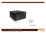
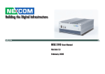
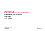
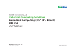
NEXCOM International Co., Ltd.
Mobile Computing Solutions
Fanless Railway Computer
nROK 500
User Manual
NEXCOM International Co., Ltd.
Published March 2014
www.nexcom.com
Contents
Contents
Preface
Chapter 3: Jumpers and Connectors
Copyright ..................................................................................................... iv
Disclaimer ..................................................................................................... iv
Acknowledgements....................................................................................... iv
Regulatory Compliance Statements ............................................................... iv
Declaration of Conformity.............................................................................. iv
RoHS Compliance........................................................................................... v
Warranty and RMA........................................................................................ vi
Safety Information ........................................................................................vii
Installation Recommendations........................................................................vii
Safety Precautions.........................................................................................viii
Technical Support and Assistance................................................................... ix
Conventions Used in this Manual................................................................... ix
Global Service Contact Information................................................................. x
Package Contents..........................................................................................xii
Ordering Information....................................................................................xiii
Before You Begin ...........................................................................................8
Precautions ....................................................................................................8
Jumper...........................................................................................................9
Locations of the Jumpers and Connectors.....................................................10
Connectors...................................................................................................11
LAN Connector (J8) ...................................................................................11
LAN LINK / ACT LED (J9).............................................................................11
Power / HDD ACCESS LED (J6) ...................................................................12
Mic-in Pin Header (J3) ................................................................................12
Line-out Pin Header (J4)..............................................................................13
DC Input Connector (CON1).......................................................................13
VGA Power Input Connector (CON2)..........................................................14
USB 2/3 Connector (J2)...............................................................................14
REAR USB connector (USB1) ......................................................................15
SATA Power Connector (CN1).....................................................................15
SATA Connector (CN2)...............................................................................16
GPIO Pin Header (J1)...................................................................................16
Clear CMOS Pin Header (J12).....................................................................17
SMBus Pin Header (J5)................................................................................17
System RESET Pin Header (JP1)....................................................................18
Disable EEPROM Write Protection (JP2).......................................................18
Thermal Sensor (Reserved Function) (JP3)....................................................19
Power Up Signal Detection Pin Header (JP7) (Reserved Feature)...................19
Power Up Manner Pin Header (JP8) (Reserved Feature)................................20
Chapter 1: Quick Reference Guide
1
Chapter 2: Product Introduction
Overview........................................................................................................3
Key Features.................................................................................................3
Hardware Specifications..................................................................................5
Copyright © 2013 NEXCOM International Co., Ltd. All rights reserved
ii
nROK 500 User Manual
Contents
MCU Debugging Pin Header (JP5).............................................................. 20
MCU Download Port (JP6)......................................................................... 21
Input Voltage Selection (SW1).................................................................... 21
GAL Download Port (JP4)........................................................................... 22
CF Connector (IDE1).................................................................................. 23
COM Port Connector (COM1 / COM2)...................................................... 24
VGA connector (VGA1)............................................................................. 24
Monitor Power Connector (J11)................................................................. 25
LED Status................................................................................................. 25
Appendix A: GPI/O Programming Guide
26
I/O Address Function.....................................................................................26
Appendix B: Watchdog Timer
Copyright © 2013 NEXCOM International Co., Ltd. All rights reserved
27
iii
nROK 500 User Manual
Preface
Preface
Copyright
Regulatory Compliance Statements
This publication, including all photographs, illustrations and software, is
protected under international copyright laws, with all rights reserved. No
part of this manual may be reproduced, copied, translated or transmitted
in any form or by any means without the prior written consent from
NEXCOM International Co., Ltd.
This section provides the FCC compliance statement for Class A devices and
describes how to keep the system CE compliant.
Declaration of Conformity
FCC
Disclaimer
This equipment has been tested and verified to comply with the limits for
a Class A digital device, pursuant to Part 15 of FCC Rules. These limits are
designed to provide reasonable protection against harmful interference when
the equipment is operated in a commercial environment. This equipment
generates, uses, and can radiate radio frequency energy and, if not installed
and used in accordance with the instructions, may cause harmful interference
to radio communications. Operation of this equipment in a residential area
(domestic environment) is likely to cause harmful interference, in which
case the user will be required to correct the interference (take adequate
measures) at their own expense.
The information in this document is subject to change without prior notice
and does not represent commitment from NEXCOM International Co.,
Ltd. However, users may update their knowledge of any product in use by
constantly checking its manual posted on our website: http://www.nexcom.
com. NEXCOM shall not be liable for direct, indirect, special, incidental, or
consequential damages arising out of the use of any product, nor for any
infringements upon the rights of third parties, which may result from such
use. Any implied warranties of merchantability or fitness for any particular
purpose is also disclaimed.
CE
Acknowledgements
The product(s) described in this manual complies with all applicable
European Union (CE) directives if it has a CE marking. For computer systems
to remain CE compliant, only CE-compliant parts may be used. Maintaining
CE compliance also requires proper cable and cabling techniques.
nROK 500 is a trademark of NEXCOM International Co., Ltd. All other product
names mentioned herein are registered trademarks of their respective owners.
Copyright © 2013 NEXCOM International Co., Ltd. All rights reserved
iv
nROK 500 User Manual
Preface
RoHS Compliance
How to recognize NEXCOM RoHS Products?
NEXCOM RoHS Environmental Policy and Status Update
For existing products where there are non-RoHS and RoHS versions, the
suffix “(LF)” will be added to the compliant product name.
NEXCOM is a global citizen for building the digital
infrastructure. We are committed to providing green
products and services, which are compliant with
European Union RoHS (Restriction on Use of Hazardous
Substance in Electronic Equipment) directive 2011/65/
EU, to be your trusted green partner and to protect
our environment.
All new product models launched after January 2013 will be RoHS compliant.
They will use the usual NEXCOM naming convention.
RoHS restricts the use of Lead (Pb) < 0.1% or 1,000ppm, Mercury (Hg)
< 0.1% or 1,000ppm, Cadmium (Cd) < 0.01% or 100ppm, Hexavalent
Chromium (Cr6+) < 0.1% or 1,000ppm, Polybrominated biphenyls (PBB) <
0.1% or 1,000ppm, and Polybrominated diphenyl Ethers (PBDE) < 0.1% or
1,000ppm.
In order to meet the RoHS compliant directives, NEXCOM has established an
engineering and manufacturing task force in to implement the introduction
of green products. The task force will ensure that we follow the standard
NEXCOM development procedure and that all the new RoHS components
and new manufacturing processes maintain the highest industry quality
levels for which NEXCOM are renowned.
The model selection criteria will be based on market demand. Vendors and
suppliers will ensure that all designed components will be RoHS compliant.
Copyright © 2013 NEXCOM International Co., Ltd. All rights reserved
v
nROK 500 User Manual
Preface
Warranty and RMA
Repair Service Charges for Out-of-Warranty Products
NEXCOM Warranty Period
NEXCOM will charge for out-of-warranty products in two categories, one is
basic diagnostic fee and another is component (product) fee.
NEXCOM manufactures products that are new or equivalent to new in
accordance with industry standard. NEXCOM warrants that products will
be free from defect in material and workmanship for 2 years, beginning on
the date of invoice by NEXCOM. HCP series products (Blade Server) which
are manufactured by NEXCOM are covered by a three year warranty period.
System Level
?? Component fee: NEXCOM will only charge for main components such as
SMD chip, BGA chip, etc. Passive components will be repaired for free,
ex: resistor, capacitor.
NEXCOM Return Merchandise Authorization (RMA)
?? Items will be replaced with NEXCOM products if the original one cannot
be repaired. Ex: motherboard, power supply, etc.
?? Customers shall enclose the “NEXCOM RMA Service Form” with the
returned packages.
?? Replace with 3rd party products if needed.
?? If RMA goods can not be repaired, NEXCOM will return it to the customer
without any charge.
?? Customers must collect all the information about the problems
encountered and note anything abnormal or, print out any on-screen
messages, and describe the problems on the “NEXCOM RMA Service
Form” for the RMA number apply process.
?? Customers can send back the faulty products with or without accessories
(manuals, cable, etc.) and any components from the card, such as CPU
and RAM. If the components were suspected as part of the problems,
please note clearly which components are included. Otherwise, NEXCOM
is not responsible for the devices/parts.
?? Customers are responsible for the safe packaging of defective products,
making sure it is durable enough to be resistant against further damage
and deterioration during transportation. In case of damages occurred
during transportation, the repair is treated as “Out of Warranty.”
?? Any products returned by NEXCOM to other locations besides the
customers’ site will bear an extra charge and will be billed to the customer.
Copyright © 2013 NEXCOM International Co., Ltd. All rights reserved
vi
nROK 500 User Manual
Preface
Board Level
▪▪ When
?? Component fee: NEXCOM will only charge for main components, such
as SMD chip, BGA chip, etc. Passive components will be repaired for free,
ex: resistors, capacitors.
▪▪ Avoid using the system near water, in direct sunlight, or near a heating
replacing parts, ensure that your service technician uses parts
specified by the manufacturer.
device.
▪▪ The
load of the system unit does not solely rely for support from the
rackmounts located on the sides. Firm support from the bottom is highly
necessary in order to provide balance stability.
If RMA goods can not be repaired, NEXCOM will return it to the customer
without any charge.
The computer is provided with a battery-powered real-time clock circuit.
There is a danger of explosion if battery is incorrectly replaced. Replace
only with the same or equivalent type recommended by the manufacturer.
Discard used batteries according to the manufacturer’s instructions.
Warnings
Read and adhere to all warnings, cautions, and notices in this guide and
the documentation supplied with the chassis, power supply, and accessory
modules. If the instructions for the chassis and power supply are inconsistent
with these instructions or the instructions for accessory modules, contact
the supplier to find out how you can ensure that your computer meets
safety and regulatory requirements.
Installation Recommendations
Ensure you have a stable, clean working environment. Dust and dirt can get
into components and cause a malfunction. Use containers to keep small
components separated.
Cautions
Electrostatic discharge (ESD) can damage system components. Do the
described procedures only at an ESD workstation. If no such station is
available, you can provide some ESD protection by wearing an antistatic
wrist strap and attaching it to a metal part of the computer chassis.
Adequate lighting and proper tools can prevent you from accidentally
damaging the internal components. Most of the procedures that follow
require only a few simple tools, including the following:
Safety Information
•
•
•
•
Before installing and using the device, note the following precautions:
?? Read all instructions carefully.
?? Do not place the unit on an unstable surface, cart, or stand.
?? Follow all warnings and cautions in this manual.
Copyright © 2013 NEXCOM International Co., Ltd. All rights reserved
A Philips screwdriver
A flat-tipped screwdriver
A grounding strap
An anti-static pad
Using your fingers can disconnect most of the connections. It is recommended
that you do not use needlenose pliers to disconnect connections as these
can damage the soft metal or plastic parts of the connectors.
vii
nROK 500 User Manual
Preface
Safety Precautions
12. If the equipment is not used for a long time, disconnect it from the
power source to avoid damage by transient overvoltage.
1.
2. Keep this User Manual for later reference.
13. Never pour any liquid into an opening. This may cause fire or electrical
shock.
3. Disconnect this equipment from any AC outlet before cleaning. Use a
damp cloth. Do not use liquid or spray detergents for cleaning.
14. Never open the equipment. For safety reasons, the equipment should
be opened only by qualified service personnel.
4. For plug-in equipment, the power outlet socket must be located near
the equipment and must be easily accessible.
15. If one of the following situations arises, get the equipment checked by
service personnel:
5. Keep this equipment away from humidity.
a. The power cord or plug is damaged.
6. Put this equipment on a stable surface during installation. Dropping it
or letting it fall may cause damage.
b. Liquid has penetrated into the equipment.
c. The equipment has been exposed to moisture.
7.
d. The equipment does not work well, or you cannot get it to work
according to the user’s manual.
e. The equipment has been dropped and damaged.
f. The equipment has obvious signs of breakage.
Read these safety instructions carefully.
Do not leave this equipment in either an unconditioned environment
o
or in a above 40 C storage temperature as this may damage the
equipment.
8. The openings on the enclosure are for air convection to protect the
equipment from overheating. DO NOT COVER THE OPENINGS.
16. Do not place heavy objects on the equipment.
9. Make sure the voltage of the power source is correct before
connecting the equipment to the power outlet.
17. The unit uses a three-wire ground cable which is equipped with a third
pin to ground the unit and prevent electric shock. Do not defeat the
purpose of this pin. If your outlet does not support this kind of plug,
contact your electrician to replace your obsolete outlet.
10. Place the power cord in a way so that people will not step on it. Do
not place anything on top of the power cord. Use a power cord that
has been approved for use with the product and that it matches the
voltage and current marked on the product’s electrical range label.
The voltage and current rating of the cord must be greater than the
voltage and current rating marked on the product.
18. CAUTION: DANGER OF EXPLOSION IF BATTERY IS INCORRECTLY
REPLACED. REPLACE ONLY WITH THE SAME OR EQUIVALENT TYPE
RECOMMENDED BY THE MANUFACTURER. DISCARD USED BATTERIES
ACCORDING TO THE MANUFACTURER’S INSTRUCTIONS.
11. All cautions and warnings on the equipment should be noted.
Copyright © 2013 NEXCOM International Co., Ltd. All rights reserved
19. The computer is provided with CD drives that comply with the
appropriate safety standards including IEC 60825.
viii
nROK 500 User Manual
Preface
Technical Support and Assistance
Conventions Used in this Manual
Warning: Information about certain situations, which if not
observed, can cause personal injury. This will prevent injury to
yourself when performing a task.
1. For the most updated information of NEXCOM products, visit NEXCOM’s
website at www.nexcom.com.
2. For technical issues that require contacting our technical support team or
sales representative, please have the following information ready before
calling:
CAUTION!
– Product name and serial number
– Detailed information of the peripheral devices
– Detailed information of the installed software (operating system,
version, application software, etc.)
– A complete description of the problem
– The exact wordings of the error messages
Caution: Information to avoid damaging components or losing
data.
Note: Provides additional information to complete a task easily.
Battery - Safety Measures
Warning!
1. Handling the unit: carry the unit with both hands and handle it with
care.
2. Maintenance: to keep the unit clean, use only approved cleaning
products or clean with a dry cloth.
3. CompactFlash: Turn off the unit’s power before inserting or removing a
CompactFlash storage card.
Caution
• Risk of explosion if battery is replaced by an incorrect type.
• Dispose of used batteries according to the instructions.
Safety Warning
This equipment is intended for installation in a Restricted Access
Location only.
Resetting the Date and Time
Note: Remember to reset the date and time upon receiving the
product. You can set them in the AMI BIOS. Refer to chapter 4
for more information.
Copyright © 2013 NEXCOM International Co., Ltd. All rights reserved
ix
nROK 500 User Manual
Preface
Global Service Contact Information
Headquarters
Japan
NEXCOM Japan
15F, No. 920, Chung-Cheng Rd.,
ZhongHe District, New Taipei City, 23586,
Taiwan, R.O.C.
Tel: +886-2-8226-7786
Fax: +886-2-8226-7782
www.nexcom.com
9F, Tamachi Hara Bldg., 4-11-5, Shiba Minato-ku,
Tokyo, 108-0014, Japan
Tel: +81-3-5419-7830
Fax: +81-3-5419-7832
Email: [email protected]
www.nexcom-jp.com
America
China
NEXCOM China
NEXCOM International Co., Ltd.
USA
NEXCOM USA
2F, Block 4, Venus Plaza, Bldg. 21,
ZhongGuanCun Software Park, No. 8,
Dongbeiwang West Rd., Haidian District,
Beijing, 100193, China
Tel: +86-10-8282-6599
Fax: +86-10-8282-5955
Email: [email protected]
www.nexcom.cn
2883 Bayview Drive,
Fremont CA 94538, USA
Tel: +1-510-656-2248
Fax: +1-510-656-2158
Email: [email protected]
www.nexcom.com
Asia
Shanghai Office
Taiwan
Central Taiwan Office
Room 603/604, Huiyinmingzun Plaza Bldg., 1,
No.609, Yunlin East Rd.,
Shanghai, 200062, China
Tel: +86-21-5278-5868
Fax: +86-21-3251-6358
Email: [email protected]
www.nexcom.cn
16F, No.250, Sec. 2, Chongde Rd., Beitun Dist., Taichung City 406, R.O.C.
Tel: +886-4-2249-1179
Fax: +886-4-2249-1172
Email: [email protected]
www.nexcom.com.tw
Copyright © 2013 NEXCOM International Co., Ltd. All rights reserved
x
nROK 500 User Manual
Preface
Europe
Shenzhen Office
Room1707, North Block, Pines Bldg.,
No.7 Tairan Rd., Futian Area,
Shenzhen, 518040, China
Tel: +86-755-8332-7203
Fax: +86-755-8332-7213
Email: [email protected]
www.nexcom.cn
Italy
NEXCOM ITALIA S.r.l
Via Gaudenzio Ferrari 29,
21047 Saronno (VA), Italia
Tel: +39 02 9628 0333
Fax: +39 02 9286 9215
Email: [email protected]
www.nexcomitalia.it
Wuhan Office
1-C1804/ 1805, Mingze Liwan,
No. 519 South Luoshi Rd.,
Hongshan District, Wuhan, 430070, China
Tel: +86-27-8722-7400
Fax: +86-27-8722-7400
Email: [email protected]
www.nexcom.cn
United Kingdom
NEXCOM EUROPE
10 Vincent Avenue,
Crownhill Business Centre,
Milton Keynes, Buckinghamshire MK8 0AB,
United Kingdom
Tel: +44-1908-267121
Fax: +44-1908-262042
Email: [email protected]
www.nexcom.eu
Chengdu Office
9F, Shuxiangxie, Xuefu Garden,
No.12 Section 1, South Yihuan Rd.,
Chengdu, 610061, China
Tel: +86-28-8523-0186
Fax: +86-28-8523-0186
Email: [email protected]
www.nexcom.cn
Copyright © 2013 NEXCOM International Co., Ltd. All rights reserved
xi
nROK 500 User Manual
Preface
Package Contents
Before continuing, verify that the package that you received is complete. Your package should have all the items listed in the following table.
Item
P/N
Name
Specification
Qty
1
50311F0110X00
FLAT HEAD SCREW
F3x5 NI NYLOK
4
2
60233SAM17X00
GSM/UMTS/HSDPA ANTENNA
ETEK:EEN-501 53.5(H)x16.8(W)mm
1
3
602DCD0375X00
CD DRIVER
4
60233PW237X00
POWER CABLE
3W3 FEMALE TO CABLE 18 AWG L=1000mm
1
Copyright © 2013 NEXCOM International Co., Ltd. All rights reserved
1
xii
nROK 500 User Manual
Preface
Ordering Information
The following provides ordering information.
• nROK 500 (P/N: 10A00050000X0)
-- Intel® Atom™ D525 1.8GHz Fanless Railway Computer with 2G
memory pre-installed and Isolated 24VDC Input
Copyright © 2013 NEXCOM International Co., Ltd. All rights reserved
xiii
nROK 500 User Manual
Chapter 1: Quick Reference Guide
Chapter 1: Quick Reference Guide
CON2
1
H10
2
1
6
1
1
1
3
JP8
JP8: Power up manner
Pin
1
3
5
1
2
3
4
5
6
CON1
6
Definition
+12VS
GND
GND
Pin
2
4
6
2
A1
R293
J12
JP5
1
3
3
1
JP7
JP6
3
JP4
1
H9
5
CON1: DC INPUT
A2
E
B
L6
SW1
2
1
2
9
1
H8
36
7
8
37
25
1
1
11
USB1
5
1
13
48
Pin
1
2
3
4
4
3
2
1
4
12
8
D1
B1
C1
H7
Definition
Normal
Clear CMOS
U16
ON
Pin
* 1-2 ( Default)
3-4
4
3
Definition
Ignition detection
Power in detection
4
3
2
1
Pin
1
2
3
4
Definition
LED_LINK#
+3.3V
LED_ACT#
+3.3V
J6: Power / HDD Status LED
Definition
12V input voltage level
not recommend
4
3
2
1
1
25
100
JP4: GAL Download Port
9
D110
C110
5
5
C54
50
B110
15
51
75
VGA1
76
A110
1
2
3
4
5
6
Pin
1
3
5
Definition
+3.3V
TCK
TDI
Pin
* 1-2
2-3
Definition
Normal
Clear CMOS
R70
U14
H6
H4
37
6
1
COM1
2
4
6
8
10
H2
1
4
C6
J3
J4
1
4
2
CE1
JP2
1
J5
10
9
J6
1
1
JP1
2
J1
1
4
CN1
2
1
CN2
1
6
+
1
+
C2
FB3
Copyright © 2013 NEXCOM International Co., Ltd. All rights reserved
Pin
1
3
5
7
9
1
Pin
1
2
3
4
Definition
Power ON#
+5V
HDD ACCESS#
+5V
J3: MIC in pin head
4
3
2
1
Pin
1
2
3
4
Definition
MIC1-L
GND
GND
MIC1-R
Write Protection
1
2
9 6
5 1
U11
C27
1
48
U4
13
H3
C10
24
B
C9
4
25
1
36
H5
1
3
5
7
9
R14
H1
Definition
GND
TDO
TMS
Pin
1
2
J1: GPIO pin head
M5
R33
12
COM2
R65
J2
Pin
2
4
6
JP2: Disable EEPROM
JP1: Reset
1
2
Definition
Ignition & Push button
Push button only
J9: LAN LINK / ACT LED
Definition
LAN1_M0P
LAN1_M0N
LAN1_M1P
LAN1_M1N
SW1: Input Voltage Selection
1
2
J7
Pin
* 1-2
2-3
1
2
3
J8: 10/100 Ethernet LAN
4
J10
CT4
J9
4
1
1
2
J11
J8
JP3
CN3
LAN1
A1
Pin
* 1-2
2-3
Pin
* 1-2
2-3
1
2
3
JP7: Power up Signal Detection
J12: Clear CMOS
1
2
3
Definition
+12VS
GND
IGNITION
Definition
EEPROM_WP
GND
J4: Line out pin head
Definition
+5V
GPIO20(Pin84)Out0
GPIO21(Pin70)Out1
GPIO22(Pin66)Out2
GPIO23(Pin48)Out3
Pin
2
4
6
8
10
Definition
GND
GPIO24(Pin36)In0
GPIO25(Pin34)In1
GPIO26(Pin33)In2
GPIO27(Pin32)In3
4
3
2
1
Pin
1
2
3
4
Definition
FRONT_OUT_LC
GND
GND
FRONT_OUT_RC
nROK 500 User Manual
Chapter 1: Quick Reference Guide
Pin No
3 4
2
1
Wire Color
Pin Out (10/100 LAN)
1
Yellow
Tx+
2
White
Rx+
3
Orange
Tx-
4
Blue
Rx-
2X Antenna
PWR HDD LNK ACT
3 4
COM2
COM1
2
1
-
+
12V OUT
SIM
+
-
IG
FUSE
CF card
24V DC IN
DC Input: 24V DC output (range:16.8V~30V)
Pin-out:
A1: + input (24V nominal)
A2: - GND
A3: Ignition Signal Input (24V,nominal;0~10.5V=off,test=on)
Copyright © 2013 NEXCOM International Co., Ltd. All rights reserved
2
nROK 500 User Manual
Chapter 2: Product Introduction
Chapter 2: Product Introduction
Overview
Front View
Rear View
Key Features
• Built-in Intel® Atom™ D525 Dual Core 1.8GHz processor
• Fanless and rugged design
• 1x M12 LAN port
• 1x external CF socket and one external SIM card holder
Copyright © 2013 NEXCOM International Co., Ltd. All rights reserved
• DC power input with 500V isolated protection
• Support ignition signal for delay-time control
• Support WoL & PXE function
• Certified by EN50155
3
nROK 500 User Manual
Chapter 2: Product Introduction
nROK 500 fanless computer with EN50155 certified is specially designed for
transportation computing solution especially in railway related applications.
Based on Intel® Atom™ D525 processor, nROK 500 is designed with isolated
DC input protection to ensure stable operation in harsh environments.
Adopting lock concept, all connectors, for example M12 Ethernet connector,
on nROK 500 are designed against vibration. Equipped with a SIM card
holder, CF socket and mini-PCIe socket for optional 3G wireless module,
nROK 500 allows data to be transmitted over network and stored in a
convenient SSD (Solid-State Drive) or CF card for better vibration and shock
protection. EN50155 certified nROK 500 is a reliable accredited solution for
railway applications.
Copyright © 2013 NEXCOM International Co., Ltd. All rights reserved
4
nROK 500 User Manual
Chapter 2: Product Introduction
Hardware Specifications
CPU
-- 1x Mic-in, Dia. 3.5mm phone jack, covered with plastic cover to
against the dust
• 1x 10/ 100 M12 LAN Port
-- LAN Controller: Intel® WG82574L LAN controller x 1
-- Support wake on LAN and boot from LAN function
• Wireless communication
-- 1x External accessible SIM card socket
-- 1x Mic-in for wireless communication use
-- 1x Speaker-out for wireless communication use
-- 2x Antenna holes (for 3G/ 3.5G mobile wireless module)
• LEDs
-- 1x LED for power status
-- 1x LED for HDD status
-- 1x LED for 10/ 100 LAN link
-- 1x LED for 10/ 100 LAN active
• DC Input
-- Nominal Voltage: 24V (Range: 16.8V ~ 30V)
-- Ignition signal input (24V, nominal; 0~10.5V = off, rest = on)
-- 500V Isolated design on DC Input
-- 1x External fuse
• Intel® Atom™ D525 Dual Core 1.8GHz
Main Chipset
• Intel® ICH-8M
Memory
• 2GB DDR2 667MHz SODIMM (up to 2GB)
Storage
• CF Card socket: External accessible type, screwed with CF card cover
• 1x 2.5” SSD drive bay
Expansion
• 1x Mini-PCIe socket (for 3.5G module option)
I/O Interface-Front
• 1x VGA Output
-- DB15 x 1, support analog monitor with pixel resolution up to 2048 x
1536@75 Hz
• 2x RS-232 COM Port
-- DB9 x 2, support 115.2 Kbps baud rate
• 2x USB Port
-- 2x USB 2.0 ports, 500mA per port, covered with plastic cover to
against the dust
• 1x Mic-in & 1 x Speaker-out
-- Audio controller: High definition audio controller, Realtek: ALC888-GR
-- 1x Speaker-out, Dia. 3.5mm phone jack, covered with plastic cover to
against the dust
Copyright © 2013 NEXCOM International Co., Ltd. All rights reserved
Operating System
• Windows Embedded Standard 2009
• Windows Embedded Standard 7
System Dimension
• 264mm (W) x 142mm (D) x 65.5mm (H)
5
nROK 500 User Manual
Chapter 2: Product Introduction
Environment
• Operating temperature
• Ambient with air: -25°C to 55°C (EN50155 Class T1)
• Storage temperature: -40°C to 80°C
• Damp heat test: 95% at 55 °C, compliance with EN50155
• Relative humidity: 0% to 90% (non-condensing)
• Vibration (Random): Compliance with EN61373 Category 1, Class B
• Shock: Compliance with EN61373 Category 1, Class B
Ingress Protection
• IP52
Certifications
• CE
• EN50155
Copyright © 2013 NEXCOM International Co., Ltd. All rights reserved
6
nROK 500 User Manual
Chapter 2: Product Introduction
142.00
94.00
115.00
60.00
25.00
nROK 500
263.50
275.60
287.60
PWR HDD LNK ACT
-
IG
FUSE
68.60
+
62.60
SIM
COM1
65.50
71.50
COM2
CF card
24V DC IN
Copyright © 2013 NEXCOM International Co., Ltd. All rights reserved
7
nROK 500 User Manual
Chapter 3: Jumpers and Connectors
Chapter 3: Jumpers and Connectors
This chapter describes how to set the jumpers on the motherboard.
Before You Begin
Precautions
▪▪ Ensure you have a stable, clean working environment. Dust and dirt can
Computer components and electronic circuit boards can be damaged by
discharges of static electricity. Working on the computers that are still
connected to a power supply can be extremely dangerous.
get into components and cause a malfunction. Use containers to keep
small components separated.
▪▪ Adequate lighting and proper tools can prevent you from accidentally
Follow the guidelines below to avoid damage to your computer or yourself:
damaging the internal components. Most of the procedures that follow
require only a few simple tools, including the following:
▪▪ Always disconnect the unit from the power outlet whenever you are
working inside the case.
• A Philips screwdriver
▪▪ If possible, wear a grounded wrist strap when you are working inside the
• A flat-tipped screwdriver
computer case. Alternatively, discharge any static electricity by touching
the bare metal chassis of the unit case, or the bare metal body of any
other grounded appliance.
• A set of jewelers Screwdrivers
• A grounding strap
▪▪ Hold electronic circuit boards by the edges only. Do not touch the
• An anti-static pad
components on the board unless it is necessary to do so. Don’t flex or
stress the circuit board.
▪▪ Using your fingers can disconnect most of the connections. It is
recommended that you do not use needle-nosed pliers to disconnect
connections as these can damage the soft metal or plastic parts of the
connectors.
▪▪ Leave all components inside the static-proof packaging that they shipped
with until they are ready for installation.
▪▪ Use correct screws and do not over tighten screws.
▪▪ Before working on internal components, make sure that the power is off.
Ground yourself before touching any internal components, by touching
a metal object. Static electricity can damage many of the electronic
components. Humid environment tend to have less static electricity than
dry environments. A grounding strap is warranted whenever danger of
static electricity exists.
Copyright © 2013 NEXCOM International Co., Ltd. All rights reserved
8
nROK 500 User Manual
Chapter 3: Jumpers and Connectors
Jumper
A jumper is the simplest kind of electric switch. It consists of two metal
pins and a cap. When setting the jumpers, ensure that the jumper caps are
placed on the correct pins. When the jumper cap is placed on both pins, the
jumper is short. If you remove the jumper cap, or place the jumper cap on
just one pin, the jumper is open.
Refer to the illustrations below for examples of what the 2-pin and 3-pin
jumpers look like when they are short (on) and open (off).
Two-Pin Jumpers: Open (Left) and Short (Right)
Three-Pin Jumpers: Pins 1 and 2 Are Short
1
2
3
Copyright © 2013 NEXCOM International Co., Ltd. All rights reserved
1
2
3
9
nROK 500 User Manual
Chapter 3: Jumpers and Connectors
Locations of the Jumpers and Connectors
H1
H5
H6
H7
A1
A110
J10
The figure below is the main board which is the board used in the nROK 500 system. It shows the locations of the jumpers and connectors.
H9
2
1
J2
J2
6
B110
B1
C110
C1
D110
CN2
6
JP4
1
D1
J7
JP6
JP4
5
1
1
3
JP5
CN2
JP7
3
JP5
JP7
1
1
JP6
1
1
J3
1
25
36
51
37
SW1
3
J12
1
JP8
B
E
CON1
CON1
25
75
C54
1
U16
CT4
24
JP8
1
JP2
J12
3
JP3
13
100
1
JP2
4
48
1
76
1
2
J5
2
1
JP1
L6
13
25
2
C10
J5
1
10
9
1
JP1
50
C9
H3
J1
J1
JP3
B
CN1
R293
SW1
J6
2
4
CN1
J6
4
12
6
36
J4
U4
C27
H8
U11
2
CON2
J9
9 6
COM2
VGA1
5
VGA1
5
1
9
11
15
Copyright © 2013 NEXCOM International Co., Ltd. All rights reserved
10
A2
9
4
1
4
USB1
1
12
J8
COM2
5 1
1
USB1
COM1
6
8
J9
R70
J8
5
H10
4
8
2
7
1
J11
A1
J11
U14
R65
COM1
1
H4
H2
1
CON2
48
2
1
CN3
C2
FB3
+
1
1
37
M5
R33
+
4
R14
C6
CE1
LAN1
J3
J4
nROK 500 User Manual
Chapter 3: Jumpers and Connectors
Connectors
LAN Connector (J8)
LAN LINK / ACT LED (J9)
A. Connector size: 1 X 4 = 4 Pin, 2.5mm, 180°, JST Connector
B. Connector location:
A. Connector size: 1 X 4 = 4 Pin, 2.0mm, 180°, JST Connector
B. Connector location:
4
4
1
Connector pin definition
1
Connector pin definition
Pin
Definition
Pin
Definition
1
LAN1_M0P
1
LED_LINK#
2
LAN1_M0N
2
+3.3V
3
LAN1_M1P
3
LED_ACT#
4
LAN1_M1N
4
+3.3V
Copyright © 2013 NEXCOM International Co., Ltd. All rights reserved
11
nROK 500 User Manual
Chapter 3: Jumpers and Connectors
Power / HDD Access LED (J6)
Mic-in Pin Header (J3)
A. Connector size: 1 X 4 = 4 Pin, 2.0mm, 180°, JST Connector
B. Connector location:
A. Connector size: 1 X 4 = 4 Pin, 2.0mm, 180°, JST Connector
B. Connector location:
4
4
1
Connector pin definition
1
Connector pin definition
Pin
Definition
Pin
Definition
1
Power ON#
1
MIC1-L
2
+5V
2
GND
3
HDD ACCESS#
3
GND
4
+5V
4
MIC1-R
Copyright © 2013 NEXCOM International Co., Ltd. All rights reserved
12
nROK 500 User Manual
Chapter 3: Jumpers and Connectors
Line-out Pin Header (J4)
DC Input Connector (CON1)
A. Connector size: 1 X 4 = 4 Pin, 2.0mm, 180°, JST Connector
B. Connector location:
A. Connector size: 1 X 6 = 6 Pin, 3.96mm, 180°, Power Connector
B. Connector location:
4
1
1
Connector pin definition
6
Connector pin definition
Pin
Definition
Pin
Definition
Pin
Definition
1
FRONT_OUT_LC
1
+12VS
2
+12VS
2
GND
3
GND
4
GND
3
GND
5
GND
6
IGNITION
4
FRONT_OUT_RC
Copyright © 2013 NEXCOM International Co., Ltd. All rights reserved
13
nROK 500 User Manual
Chapter 3: Jumpers and Connectors
VGA Power Input Connector (CON2)
USB 2/3 Connector (J2)
A. Connector size: 1 X 2 = 2 Pin, 3.96mm, 180°, Power Connector
B. Connector location
A. Connector size: 1 X 6 = 6 Pin, 2.0mm, 180°, JST Connector
B. Connector location
1
1
2
Connector pin definition
Pin
6
Connector pin definition
Definition
Pin
Definition
Pin
Definition
1
+12VSD
1
+5V
2
Data 2N
2
GND
3
Data 2P
4
Data 3N
5
Data 3P
6
GND
Copyright © 2013 NEXCOM International Co., Ltd. All rights reserved
14
nROK 500 User Manual
Chapter 3: Jumpers and Connectors
REAR USB connector (USB1)
SATA Power Connector (CN1)
A. Connector size: double layer standard USB, edge connector
B. Connector location
A. Connector size: 1 X 4 = 4 Pin, 2.54mm, 180°, JST Connector
B. Connector location
1
4
1
5
4
8
Connector pin definition
Connector pin definition
Pin
Definition
Pin
Definition
Pin
Definition
1
+5V
5
+5V
1
+12V
2
Data 0N
6
Data 1N
2
GND
3
Data 0P
7
Data 1P
3
GND
4
GND
8
GND
4
+5V
Copyright © 2013 NEXCOM International Co., Ltd. All rights reserved
15
nROK 500 User Manual
Chapter 3: Jumpers and Connectors
SATA Connector (CN2)
GPIO Pin Header (J1)
A. Connector size: 1 X 7 = 7Pin, 1.27mm, 180°, standard SATA connector
B. Connector location
A. Connector size: 2 X 5 = 10 Pin, 2.0mm, 180°, pinhead
B. Connector location
1
7
Connector pin definition
2
10
1
9
Connector pin definition
Pin
Definition
Pin
Definition
Pin
Definition
Pin
Definition
1
GND
2
TXP0
1
+5V
2
GND
3
TXN0
4
GND
3
GPIO20(Pin84)Out0
4
GPIO24(Pin36)In0
5
RXN0
6
RXP0
5
GPIO21(Pin70)Out1
6
GPIO25(Pin34)In1
7
GND
7
GPIO22(Pin66)Out2
8
GPIO26(Pin33)In2
9
GPIO23(Pin48)Out3
10
GPIO27(Pin32)In3
Copyright © 2013 NEXCOM International Co., Ltd. All rights reserved
16
nROK 500 User Manual
Chapter 3: Jumpers and Connectors
Clear CMOS Pin Header (J12)
SMBus Pin Header (J5)
A. Connector size: 1 X 3 = 3 Pin, 2.54mm, 180°, pinhead
B. Connector location
A. Connector size: 1 X 3 = 3 Pin, 2.54mm, 180°, pinhead
B. Connector location
1
3
1
Connector pin definition
3
Connector pin definition
Pin
Setting
Pin
Definition
1-2
Normal
1
I2C CLK
2-3
Clear CMOS
2
I2C DATA
3
GND
1-2 On: default
Copyright © 2013 NEXCOM International Co., Ltd. All rights reserved
17
nROK 500 User Manual
Chapter 3: Jumpers and Connectors
System RESET Pin Header (JP1)
Disable EEPROM Write Protection (JP2)
A. Connector size: 1 X 2 = 2 Pin, 2.54mm, 180°, pinhead
B. Connector location
A. Connector size: 1 X 2 = 2 Pin, 2.54mm, 180°, pinhead
B. Connector location
1
2
1
Connector pin definition
2
Connector pin definition
Pin
Definition
Pin
Definition
1
RSET
1
EEPROM_WP
2
GND
2
GND
Copyright © 2013 NEXCOM International Co., Ltd. All rights reserved
18
nROK 500 User Manual
Chapter 3: Jumpers and Connectors
Thermal Sensor (Reserved Function) (JP3)
Power Up Signal Detection Pin Header (JP7) (Reserved Feature)
A. Connector size: 1 X 2 = 2 Pin, 2.54mm, 180°, pinhead
B. Connector location
A. Connector size: 1 X 3 = 3 Pin, 2.54mm, 180°, pinhead
B. Connector location
1
2
1
Connector pin definition
3
Connector pin definition
Pin
Definition
Pin
Setting
1
Sensor
1-2
Ignition detection
2
GND
2-3
Power in detection
1-2 On: default
Copyright © 2013 NEXCOM International Co., Ltd. All rights reserved
19
nROK 500 User Manual
Chapter 3: Jumpers and Connectors
Power Up Manner Pin Header (JP8) (Reserved Feature)
MCU Debugging Pin Header (JP5)
A. Connector size: 1 X 3 = 3 Pin, 2.54mm, 180°, pinhead
B. Connector location
A. Connector size: 1 X 3 = 3 Pin, 2.54mm, 180°, pinhead
B. Connector location
1
3
1
Connector pin definition
3
Connector pin definition
Pin
Setting
Pin
Definition
1-2
Ignition & Push button
1
TX0
2-3
Push button only
2
RX0
3
GND
1-2 On: default
Copyright © 2013 NEXCOM International Co., Ltd. All rights reserved
20
nROK 500 User Manual
Chapter 3: Jumpers and Connectors
Input Voltage Selection (SW1)
A. Connector size: 1 X 5 = 5 Pin, 2.54mm, 180°, pinhead
B. Connector location
A. Connector size: 1 X 2 = 2 Pin DIP Switch
B. Connector location
O
N
MCU Download Port (JP6)
5
1
2
1
Connector pin definition
Connector pin definition
Pin
Definition
Pin
Definition
Pin
Definition
1
+3.3ALW
2
C2D
1-2
12V input voltage level
3
MRST
4
C2CK
2
Wide range 8~60V voltage input (reserved feature)
5
GND
Copyright © 2013 NEXCOM International Co., Ltd. All rights reserved
1-2 On: default
21
nROK 500 User Manual
Chapter 3: Jumpers and Connectors
GAL Download Port (JP4)
A. Connector size: 1 X 6 = 6 Pin, 2.54mm, 180°, pinhead
B. Connector location
1
6
Connector pin definition
Pin
Definition
Pin
Definition
1
+3.3V
2
GND
3
TCK
4
TDO
5
TDI
6
TMS
Copyright © 2013 NEXCOM International Co., Ltd. All rights reserved
22
nROK 500 User Manual
Chapter 3: Jumpers and Connectors
CF Connector (IDE1)
A. Connector size: Standard TYPE 2 connector with ejection
B. Connector location
Connector pin definition
Pin
Definition
Pin
Definition
Pin
Definition
Pin
Definition
1
GND
26
CF_CD1#
11
GND
36
VCC
2
SDD3A
27
SDD11A
12
GND
37
HDIRQ14
3
SDD4A
28
SDD12A
13
VCC
38
VCC
4
SDD5A
29
SDD13A
14
GND
39
CF_SEL#
5
SDD6A
30
SDD14A
15
GND
40
NC
6
SDD7A
31
SDD15A
16
GND
41
IDERST#
7
SDCS#1
32
SDCS#3
17
GND
42
SIORDY
8
GND
33
NC
18
SDA2A
43
SDREQ
9
GND
34
SDIOR#
19
SDA1A
44
SDDACK#
10
GND
35
SDIOW#
20
SDA0A
45
IDEACTP#
11
GND
36
VCC
21
SDD0A
46
DIAG#
12
GND
37
HDIRQ14
22
SDD1A
47
SDD8A
13
VCC
38
VCC
23
SDD2A
48
SDD9A
14
GND
39
CF_SEL#
24
NC
49
SDD10A
15
GND
40
NC
25
CF_CD2#
50
GND
Copyright © 2013 NEXCOM International Co., Ltd. All rights reserved
23
nROK 500 User Manual
Chapter 3: Jumpers and Connectors
COM Port Connector (COM1 / COM2)
VGA connector (VGA1)
A. Connector size: Standard COM DB9, 90°
B. Connector location
A. Connector size: Standard VGA connector DB 15, 90°
B. Connector location
6
1
1
5
11
15
5
9
Connector pin definition (COM1)
Connector pin definition (COM1)
Pin
Definition
Pin
Definition
Pin
Definition
Pin
Definition
1
DCD2
6
DSR#2
1
RED_VGA
9
VGA_VCC
2
RX2
7
RTS#2
2
GREEN_VGA
10
GND
3
TX2
8
CTS#2
3
BLUE_VGA
11
NC
4
DTR#2
9
RI#2
5
GND
Connector pin definition (COM2)
Pin
Definition
Pin
Definition
1
DCD1
6
DSR#1
2
RX1
7
RTS#1
3
TX1
8
CTS#1
4
DTR#1
9
RI#1
5
GND
Copyright © 2013 NEXCOM International Co., Ltd. All rights reserved
24
4
NC
12
VGA_DDC_DATA
5
GND
13
G_HSYNC
6
GND
14
G_VSYNC
7
GND
15
VGA_DDC_CLK
8
GND
nROK 500 User Manual
Chapter 3: Jumpers and Connectors
Monitor Power Connector (J11)
LED Status
A. Connector size: FCI Power connector , 90°
B. Connector location
LED5: COMEXPRESS TYPE2 ID identification
C
LED5
A
LED_G_0603
A2
A1
LED 1~4 / 6~9 : BIOS POST Display (Port 80)
LED 1~4 : High Byte
LED 6~9 : Low Byte
Connector pin definition (COM1)
Pin
Definition
A1
+12V
A2
GND
Copyright © 2013 NEXCOM International Co., Ltd. All rights reserved
25
nROK 500 User Manual
Appendix A: GPI/O Programming Guide
Appendix A: GPI/O Programming Guide
I/O Address Function
Digital I/O (Digital Input/Output) pins are provided for custom system design.
This appendix provides definitions and its default setting for the Digital I/O
pins in the nROK 500. The pin definition is shown in the following table:
Pin
Definition
Pin
Bit0 : GPO20
Bit1 : GPO21
Bit2 : GPO22
Bit3 : GPO23
Bit4 : GPI 24
Bit5 : GPI 25
Bit6 : GPI 26
Bit7 : GPI 27
Definition
1
+5V
2
GND
3
GPIO20(Pin84)Out0
4
GPIO24(Pin36)In0
5
GPIO21(Pin70)Out1
6
GPIO25(Pin34)In1
7
GPIO22(Pin66)Out2
8
GPIO26(Pin33)In2
9
GPIO23(Pin48)Out3
10
GPIO27(Pin32)In3
Copyright © 2012 NEXCOM International Co., Ltd. All rights reserved
IO base address : 800h
1. Read/Write GPIO data by I/O port 801h
26
nROK 500 User Manual
Appendix B: Watchdog Timer
Appendix B: Watchdog Timer
nROK 500 Watch Dog Function Configuration Sequence Description:
Start
Step1. See “SetupWDT” procedure
#Setup Watchdog Timer Environment
Step2. See “TimeBaseWDT” procedure
#Initial Watchdog Timer.
Users can select second or minute.
Step3. See “TimeCountWDT” procedure
#Set Watchdog Timer Time-out Value.
Users can set time-out value.
Step4: See ExitSetup procedure
#Exit Setup Environment
End
Copyright © 2012 NEXCOM International Co., Ltd. All rights reserved
27
nROK 500 User Manual
Appendix B: Watchdog Timer
out
2fh, al
ret
TimeBaseWDTENDP
===============================================
SetupWDTPROC
mov
dx, 2eh
mov
al, 087h
out
dx, al
nop
nop
mov
al, 01h
out
dx, al
nop
nop
mov
al, 55h
out
dx, al
nop
nop
out
dx, al
;Write operations to special address
port (2E) for entering MB PnP Mode.
===============================================
TimeCountWDTPROC
mov
al, 73h ;WDT Time-out register.
out
2eh, al
mov
al, 03h ;Here!! Set count 3.
out
2fh, al
ret
TimeCountWDTENDP
===============================================
ExitSetup
PROC
mov
dx, 2eh
mov
al, 0AAh
out
dx, al
ExitSetup
ENDP
===============================================
mov
al, 07h
out
2eh, al
mov
al, 08h ;Select logical device for Watch Dog.
out
2fh, al
ret
SetupWDTENDP
c:\>debug [enter]
-o 2e 87 ;Enter the Extended Function Mode
-o 2e 01
-o 2e 55
-o 2e 55
-o 2e 07 ;Logical Device Number Reg
-o 2f 07 ;LDN=7
-o 2e 72 ;Watch dog configuration
-o 2f XX ;minute mode (-o 2f 00 second mode)
-o 2e 73 ;LSB for Watch dog tme out value
===============================================
TimeBaseWDT
PROC
mov
al, 72h
out
2eh, al
mov
al, 40h ;Set WDT reset upon KBRST#
or
al, 00h ;Here!! set 00h for second, set 80h for minute
Copyright © 2012 NEXCOM International Co., Ltd. All rights reserved
28
nROK 500 User Manual
Appendix B: Watchdog Timer
-o 2f YY
-o 2e 74 ;MSB for Watch dog tme out value
-o 2f ZZ
XX: DO : Second mode with KRST (Bit 6)
50 : minute mode with KRST (Bit 6)
ex:
10 second timeout:
xx=D0
yy=0a
zz=00
Copyright © 2012 NEXCOM International Co., Ltd. All rights reserved
29
nROK 500 User Manual