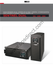
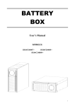
1
Uninterruptible Power Supply ON LINE MULTISTANDARD 6500 VA - 8000 VA - 10000 VA Manuale d’uso - User’s Manual - Bedienungsanleitung Manuel d’utilisateur - Manual de Usuario 4 GB SAFETY GB This part of the manual contains precautions that must be adhered to strictly since they regard SAFETY. a) THE UPS MUST NOT OPERATE WITHOUT AN EARTH CONNECTION. The first connection to be carried out is the earth conductor, which has to be connected to the terminal marked . b) Avoid connecting the output neutral to the input neutral or to earth as this could cause malfunctions. c) DANGEROUS electrical voltages are generated inside the UPS. All installation and maintenance operations must be carried out EXCLUSIVELY by authorized personnel. d) The UPS contains an internal power source: the batteries. The terminals and the output sockets may be powered even when the UPS is not connected to the mains. e) The total battery voltage can generate an electric shock. Replaced batteries should be considered as TOXIC WASTE and treated as such. Do not throw the battery packs into fire: they may explode. Do not try to open the battery packs: they do not require any maintenance. Furthermore the electrolyte is dangerous if it comes into contact with the skin or the eyes and may be toxic. f) Do not switch the UPS on if there is any leak of liquid, or if a residual white powder is noted. g) Do not allow water, liquids in general and/or other foreign bodies to get into the UPS. h) In the event of dangerous conditions switch the UPS off with the switch located on the front panel and open the magneto-thermal protection installed upstream of the UPS. Isolate the battery by removing the lower part of the front panel and disconnecting the two battery pack connectors. i) The UPS generates a leakage current of less than 2 mA. Warning: the leakage current of the load is added to that of the UPS on the earth protection conductor. j) For battery expansion use exclusively connectors supplied by or authorized by the manufacturers. k) The UPSs of this series have been designed for professional use and are therefore not suitable for use in a domestic environment. 6 GB USER MANUAL GB 51 INTRODUCTION Thank you for choosing our product. The manufacturers are highly specialized in the development and production of uninterruptible power systems (UPS). The UPSs of this series are high quality products, designed and manufactured to ensure optimum performance. This device can be used by anyone, provided that they READ THIS MANUAL CAREFULLY AND THOROUGHLY BEFOREHAND. This manual contains detailed instructions for the use and installation of the UPS. For information on use and in order to get the most out of this device, this manual should be kept close to the UPS and CONSULTED BEFORE CARRYING OUT ANY OPERATIONS ON IT. © No part of this manual may be reproduced, even partially, without the manufacturer’s authorization. For purposes of improvements the manufacturer reserves the right to modify the described product at any time and without notice. CONTENTS PRESENTATION UPS VIEWS BATTERY BOX VIEWS DISPLAY MASK VIEW INSTALLATION OPENING THE PACKAGING AND CHECKING ITS CONTENTS TOWER VERSION RACK VERSION INSTALLATION PROCEDURES CONNECTING THE UPS TO THE BATTERY BOX USE CONNECTIONS 54 55 56 57 58 58 60 61 62 63 64 64 8-10kVA single phase version 65 Three phase version 66 Version with external Bypass remote control FIRST START-UP START-UP FROM MAINS START-UP FROM BATTERY UPS SHUTDOWN DISPLAY PANEL INDICATIONS 67 69 69 69 69 70 UPS status indicators 70 Measurements display area 71 Single phase version 71 Three phase version 72 Configuration area OPERATING MODES R.E.P.O. PROGRAMMABLE AUXILIARY SOCKET (POWER SHARE) UPS CONFIGURATION COMMUNICATION PORTS RS232 and USB connectors Communication Slot SOFTWARE 73 74 74 74 75 77 77 77 78 Monitoring and control software 78 Configuration software 78 TROUBLESHOOTING 79 ALARM CODES TECHNICAL DATA TABLE SINGLE/SINGLE PHASE UPS TECHNICAL DATA TABLE THREE/SINGLE PHASE UPS TECHNICAL DATA TABLE BATTERY BOX TECHNICAL DATA TABLE TABLE OF OVERLOAD TIMES 81 83 83 84 85 85 53 PRESENTATION This new family of UPSs has been designed with versatility in mind. These UPSs can in fact be installed either in a tower version or in a rack version, according to requirements. The 2 different versions of the product are shown below: Tower Rack 6500 (three phase only) Nominal power Nominal voltage Dimensions H x L x D Weight (1) [VA] [Vac] [mm] [Kg] 6500 approx 28 + 63 8000 10000 8000 220/230/240 2 x [455 x 175 x 660] (1) approx 29 + 65 10000 approx 30 + 65 The H dimension is different in the rack version with handles mounted: 483mm x 175mm x 660mm (H x L x D) Note: 175mm = 4U 483mm = 19” PRESENTATION UPS VIEWS Release slots Rotatable display mask Manual bypass switch General switch Removable front panel Front view (with front panel removed) (with front panel) Battery expansion connector Cooling fan Remote emergency power off (R.E.P.O.) COMMUNICATION expansion slot RS232 communication port IEC 10 A Power share sockets Cooling fan USB communication port Power share sockets thermal protection IN/OUT connections drawer Rear view 55 PRESENTATION BATTERY BOX VIEWS Release slots Extractable/rotatable mask Removable front panel Front view Ventilation grille Connectors for battery expansion Fuse-holder disconnecting switches Rear view PRESENTATION DISPLAY MASK VIEW “SEL / SET” button “ON” button “STBY” button 11 9 10 8 1 2 LCD Display 3 4 5 6 7 1 Normal operation 7 Configuration area 2 Operation from mains 8 Maintenance request 3 Operation from battery 9 Timer 4 Load powered by the bypass 10 Measurement display area 5 Battery back up time indicator 11 Stand-by/alarm 6 Load level indicator 57 INSTALLATION OPENING THE PACKAGING AND CHECKING ITS CONTENTS After opening the packaging, first check the contents. The packaging should contain the following: UPS Battery box 1 cable guide + 2 seal stops 6 plastic covers (upper panels UPS and Battery box) Ferrules for cables - terminal board connection 2 plastic keys to release display 2 Handles kits RS232 serial cable INSTALLATION UPS-Battery box connection cable 2 Fuses for Battery box - 14x51 mm, 50A, 400V User manual + CD-ROM software User's manual 59 INSTALLATION WARNING: this UPS product conforms to the current electromagnetic compatibility (EMC) regulations (C2 class). It may cause radio interference in the home environment. The user may have to adopt supplementary measures. TOWER VERSION This chapter describes the operations required to prepare the UPS and the Battery box for use in the tower version. WARNING: for your safety and that of your product, the information set out below should be followed carefully. BEFORE CARRYING OUT THE FOLLOWING SEQUENCE OF OPERATIONS, ENSURE THAT THE UPS IS COMPLETELY SWITCHED OFF AND NOT CONNECTED TO THE ELECTRICITY MAINS OR TO ANY LOAD Once removed from the packaging, the UPS and the Battery box are ready for installation in a tower configuration. All that is needed to complete this configuration is to mount the six plastic covers provided, three in the upper part of the UPS and the other three in the upper part of the Battery box, as described below: The three covers have an interlocking system: locate the cover mounting holes in the upper part of the UPS and of the Battery box and very carefully engage them by exerting gentle pressure (see figure at side). INSTALLATION RACK VERSION The sequence of operations required to convert the UPS and the Battery box into the rack version is described below. WARNING: for your safety and that of your product, the information set out below should be followed carefully. BEFORE CARRYING OUT THE FOLLOWING SEQUENCE OF OPERATIONS, ENSURE THAT THE UPS IS COMPLETELY SWITCHED OFF AND NOT CONNECTED TO THE ELECTRICITY MAINS OR TO ANY LOAD 1 - First remove the feet at the base of the UPS and Battery box. Put the UPS and the Battery box into a horizontal position very carefully, and with a small slotted screwdriver carefully lift the pin at the centre of the foot. Once it has been lifted, remove the foot from the bases of the UPS and Battery box. Repeat these operations for the remaining feet. The exact sequence to follow is shown at the side: 1 2 2 - Once all the feet have been removed, the display mask must then be rotated. Insert the keys provided in the release slots located at the sides of the display mask and exert enough gentle pressure to release the mask from the UPS, as shown in the figure at the side. Repeat the same operations to release the mask from the Battery box. 3 - WARNING: The display mask is connected to the UPS by means of a cable. The mask must therefore be removed very carefully, without pulling or exerting undue force, in order to avoid damaging the display and/or the UPS. DO NOT TRY TO SEPARATE THE DISPLAY MASK FROM THE UPS IN ANY WAY. 4 - Rotate the mask 90° anticlockwise and reengage it in the UPS by carefully inserting it in the housing until a slight click is heard with the mask remaining in position. Do the same to rotate and reengage the mask to the Battery box. NOTE: The pressure must be exerted near the release slots 5 - Rotate the UPS and the Battery box 90° clockwise taking the utmost care 61 INSTALLATION 6 - At this point, with the UPS and the Battery box in a horizontal position, fasten the handles to the sides of the UPS and Battery box with the screws as shown in the figures below. NOTE: The UPS and Battery box are compatible for mounting in standard rack cabinets of 600mm x 800mm or more (in width). Support brackets (guides with L-shaped support) must be used in rack installations due to the weight of the UPS and of the Battery box. It is recommended to install the UPS above the Battery box and in the lower part of the rack cabinet for the same reason. The manufacturers cannot accept liability for damage caused by wrong connections or by operations other than those described in this manual. INSTALLATION PROCEDURES Before connecting the UPS to the Battery box, ensure compliance with the following points: ¾ Install the UPS and the Battery box on a flat, stable surface. ¾ Avoid placing in positions exposed to direct sunlight or hot air ¾ Maintain room temperature between 0°C and 40°C N.B.: the UPS can operate with an ambient temperature of between 0°C and 40°C. The optimal operating temperature for the batteries inside the Battery box is between 20 and 25°C. If the operational lifetime of the batteries is an average of 4 years with an ambient temperature of 20°C, this will be halved if the temperature goes up to 30°C. ¾ The ambient humidity rate must not exceed 90%. ¾ Avoid dusty environments. ¾ Ensure that the UPS and the Battery box are placed with the front and the rear at least 10 cm away from walls. Do not place objects on top of the ventilation holes in order to allow adequate ventilation. ¾ The cable connecting the UPS to the Battery box must not be extended by the user. Contact the supplier in case of need. INSTALLATION CONNECTING THE UPS TO THE BATTERY BOX ¾ Connect the UPS to the Battery box by means of the expansion cable provided (see figure below) ¾ Insert the two fuses provided into the fuse-holder disconnecting switches at the back of the Battery box. Close the disconnecting switches. ¾ The cable can be connected to either of the two sockets located at the back of the Battery box. ¾ The remaining unused expansion socket at the back of the Battery box can be used for the cascade connection of further Battery boxes to increase UPS autonomy. WARNING: Only one UPS can be connected for each Battery box or for several cascade-connected Battery boxes. 63 USE CONNECTIONS INSTALLATION MUST BE CARRIED OUT EXCLUSIVELY BY QUALIFIED PERSONNEL. THE FIRST CONNECTION TO BE CARRIED OUT IS THE PROTECTION CONDUCTOR (EARTH CABLE), TO BE INSERTED IN THE TERMINAL MARKED . THE UPS MUST NOT BE OPERATED WITHOUT BEING CONNECTED TO THE EARTHING SYSTEM. Warning: if the neutral (N) and phase (F) instructions are observed for the plugs and sockets, the UPS will not change the existing neutral arrangements when inserted in a system. The resistance on the neutral connection is less than 0.1 ohm. A differential switch placed upstream will also be triggered for a fault occurring downstream of the UPS. The sensitivity of this switch has to take into account the leakage current of the unit (approx. 2 mA) and of the load which are added together on the UPS earth conductor. The neutral arrangements will only be changed if an isolation transformer is connected or when the UPS is operating with the neutral isolated upstream. Avoid connecting the output neutral to the input neutral or to earth as this could damage the UPS . For the mains and load connections follow the instructions below: 1. Install a 63A magneto-thermal switch with B or C trip curve (4 poles for three phase versions, 2 poles for single phase versions) upstream of the device. 2. The terminals to be used for the connection of the input and output lines are located inside the IN/OUT connections drawer. Undo the screw securing the connections drawer located on the right-hand side of the drawer (see figure at side). 3. Pull the drawer out as much as is needed for the terminals to be easily accessible (see figure at side). WARNING: the drawer has a locking system to prevent it being pulled out completely. Do not try to remove the drawer completely. USE 8-10kVA single phase version 1. Use 3 cables with 10 mm2 section (EARTH, N and L) in input, and 3 cables with 10 mm2 section for the output (EARTH, N and L). With reference to the figure shown at the side: - Insert the cables from the 63A magneto-thermal switch into seal stop P2 (input line). - Insert the cables from the load into seal stop P1 (output line). - Strip the cables observing the measurements provided. - Insert the part that has just been stripped into the ferrules provided. 2. Connect the wires to the relative terminals strictly following the instructions set out below: Input line a - Ensure that the magneto-thermal switch upstream is open. b - Connect the earth wire to terminal 3. c - Connect the neutral wire to terminal 1. d - Connect the phase wire to terminal 2. Output line a - Connect the earth wire to terminal 6. b - Connect the neutral wire to terminal 7. c - Connect the phase wire to terminal 8. Bypass line a - Ensure that a jumper is connected at terminals 9 and 10; this is needed for the correct operation of the UPS. 3. Secure the cable guides to the flange, close the drawer and secure it with the screw removed previously. 65 USE Three phase version 1. (8-10kVA THREE PHASE VERSION): Use 3 cables with 6 mm2 section (EARTH, L2 and L3) and 2 with 10 mm2 section (N, L1) in input (N.B.: L1 and N have a greater section because in operation from bypass they have to carry all the input current). For the output use 3 cables with 10 mm2 section (EARTH, N and L). With reference to the figure shown at the side: - Insert the cables from the 63A magneto-thermal switch into seal stop P2 (input line). - Insert the cables from the load into seal stop P1 (output line). - Strip the cables observing the measurements provided. - Insert the part that has just been stripped into the ferrules provided. (6,5kVA THREE PHASE VERSION): Use 3 cables with 4 mm2 section (EARTH, L2 and L3) and 2 with 6 mm2 section (N, L1) in input (N.B.: L1 and N have a greater section because in operation from bypass they have to carry all the input current). For the output use 3 cables with 6 mm2 section (EARTH, N and L). With reference to the figure shown at the side: - Insert the cables from the 63A magneto-thermal switch into seal stop P2 (input line). - Insert the cables from the load into seal stop P1 (output line). - Strip the cables observing the measurements provided. - Insert the part that has just been stripped into the ferrules provided. 2. Connect the wires to the relative terminals strictly following the instructions set out below: Input line a - Ensure that the magneto-thermal switch upstream is open. b - Connect the earth wire to terminal 5. c - Connect the neutral wire to terminal 1. d - Connect the phase wires to terminals 2, 3 and 4 (use the red wire for L1). Output line a - Connect the earth wire to terminal 6. b - Connect the neutral wire to terminal 7. c - Connect the phase wire to terminal 8. Bypass line a - Ensure that a jumper is connected at terminals 9 and 10; this is needed for the correct operation of the UPS. 3. Secure the cable guides to the flange, close the drawer and secure it with the screw removed previously. USE Version with external Bypass remote control If it is required to make the Bypass remote maintenance control external, follow points 1, 2 and 3 as described above. Then continue as shown below: 1. Remove the plug from the first hole at the top of the removable drawer and mount the cable guide provided. 2. Follow the instructions described above for the connection, number and section of the cables to be used, passing through seal stops P1 and P2. Use a 2x0.75 mm2 cable for connection with the remote Bypass terminals. With reference to the figure shown at the side: - Insert the Bypass external control cable to the inside of cable guide P3. - Strip the cables observing the measurements provided. - Insert the part that has just been stripped into the ferrules provided. 3. Connect the wires to the relative terminals strictly following the instructions described above. The Bypass line can be connected to the UPS in single phase or three phase connection. Connect the wires of the Bypass line as follows: Bypass line a - Connect the two wires of the cable to terminals 9 and 10 for the external control of the remote Bypass. 67 USE Secure the cable guide and the seal stop to the flange, close the drawer and secure it with the screw removed previously. A WARNING LABEL MUST BE AFFIXED TO ALL MAINS POWER ISOLATING SWITCHES INSTALLED FAR FROM THE UPS AREA, IN ORDER TO REMIND SUPPORT SERVICE PERSONNEL THAT THE CIRCUIT IS CONNECTED TO A UPS. THE LABEL MUST CARRY THE FOLLOWING MESSAGE: ISOLATE THE UNINTERRUPTIBLE POWER SYSTEM (UPS) BEFORE WORKING ON THIS CIRCUIT USE FIRST START-UP 1) Ensure that all the operations described in the paragraph above, “Connections”, have been carried out correctly. 2) Close the magneto-thermal switch located upstream of the UPS. 3) Press the general switch located on the front panel. 4) The UPS will start up after a few seconds; the display will come on, a beep will be emitted and the icon will flash. The UPS is now in stand-by state: this means that the UPS is in a minimum consumption condition. The microcontroller is powered and carries out monitoring and autodiagnostics tasks; the batteries are charging; everything is ready to activate the UPS. There is also a stand-by state during operation from battery if the timer is activated. 5) Check the settings on the display (see paragraph: Configuration area) START-UP FROM MAINS 1) Press the “ON” button. When this is pressed all the icons on the display will light up for 1 second and the UPS will emit a beep. 2) Switch on the equipment connected to the UPS. Only for the first start-up: after approx. 30 sec., check that the UPS is operating correctly: 1. Simulate a black-out by opening the switch connected upstream of the UPS. 2. The load must continue to be powered, the icon should appear on the display and a beep should be heard every 4 seconds. 3. If the switch upstream is closed again the UPS must go back to operating from the mains. START-UP FROM BATTERY 1) Press the general switch located on the front panel. 2) Keep the “ON” button pressed for at least 5 seconds. All the icons on the display will light up for 1 second and the UPS will emit a beep. 3) Switch on the equipment connected to the UPS. UPS SHUTDOWN To switch the UPS off, keep the “STBY” key pressed down for at least 1.5 seconds. The UPS will return to icon will start to flash: the stand-by condition and the a) If the mains is present, the general switch must be pressed so that it returns to its original position (raised position) to switch the UPS off completely. b) If the UPS is operating from battery and the timer has not been set, it will automatically switch off completely after 5 seconds. If however the timer has been set, the “STBY” key has to be pressed for at least 5 seconds to switch off the UPS. If it is required for the UPS to stay completely switched off when mains power returns, the general switch has to be pressed (see point a.). WARNING: the UPS is equipped with an emergency redundant power supply which, in the event of a UPS failure, will act to avoid the load being shut off by switching it on to the bypass. If you switch the UPS off simply be pressing the main switch (without first putting it in stand-by as explained in the manual), the load will still be powered by the bypass. 69 USE DISPLAY PANEL INDICATIONS This section describes in detail all the information that can be shown on the LCD display. In order to make it clearer, all the information displayed can be divided into three main groups: ¾ UPS status indicators ¾ Measurements display area ¾ Configuration area UPS status indicators ICON STATUS DESCRIPTION Constant Indicates a fault Flashing The UPS is in stand-by state Constant Indicates regular operation Constant The UPS is operating from the mains Flashing The UPS is operating from the mains, but the output voltage is not synchronized with the mains voltage Constant The UPS is operating from the battery. When it is in this state the UPS emits an acoustic signal (beep) at regular intervals of 4 sec. Flashing End of discharge prealarm. Indicates that the battery back up time is coming to an end. In this condition the UPS emits a beep at regular intervals of 1 sec. Constant Indicates that the loads connected to the UPS are powered from the bypass Dynamic Indicates the estimated percentage of back-up time Dynamic Indicates the % of load applied to the UPS with respect to the nominal value Flashing A maintenance operation is required Constant Flashing Indicates that the timer is activated (programmed start-up or shutdown). The timer can be activated/deactivated via the software provided 1 minute to go before the UPS starts up or 3 minutes before it shuts down USE Measurements display area The most important measurements relating to the UPS can be shown in sequence on the display. When the UPS is started up, the display shows the value of the mains voltage. To go to a different display press the “SEL/SET” button repeatedly until the required measurement is displayed. If a fault/alarm (FAULT) or a lock (LOCK) should occur, the type and corresponding alarm code is automatically shown on the display. Single phase version Some examples are shown below: GRAPHIC EXAMPLE (1) DESCRIPTION GRAPHIC EXAMPLE (1) DESCRIPTION Mains voltage Total battery voltage Mains frequency Percentage of the applied load Voltage output from the UPS Current absorbed by the load Output voltage frequency Temperature of the cooling system for the UPS internal electronics Residual battery back up time Fault/Alarm (2): the corresponding code is displayed Percentage of battery charge Lock (2): the corresponding code is displayed (1) The values shown in the images in the table are purely indicative. (2) The FAULT/LOCK codes can only be displayed if they are active (i.e., if there is a fault/alarm or a lock). 71 USE Three phase version Some examples are shown below: GRAPHIC EXAMPLE (1) DESCRIPTION GRAPHIC EXAMPLE (1) DESCRIPTION Percentage of battery charge Voltage phase 1 (2) Total battery voltage Percentage of the applied load Voltage phase 2 (2) Current absorbed by the load Temperature of the cooling system for the UPS internal electronics Voltage phase 3 (2) Fault/Alarm (3): the corresponding code is displayed Output voltage frequency Lock (3): the corresponding code is displayed Residual battery back up time (1) The values shown in the images in the table are purely indicative. (2) Alternative indication Phase No./Voltage. (3) The FAULT/LOCK codes can only be displayed if they are active (i.e., if there is a fault/alarm or a lock). USE Configuration area The configuration area groups together the main UPS operating parameters and displays its current status. The parameters contained in this area can be changed directly from the display panel. SETTABLE PARAMETERS: Frequency: Output voltage frequency Frequency Voltage: Output voltage Mode: UPS operating mode Voltage Mode The image at the side shows the display zone for the settings (configuration area) showing the three settable parameters. How to change the settings: To access the configuration area, hold the “SEL/SET” button down for at least 2 sec. The word “SET” will light up and an arrow ( ► ) will appear to the left of Frequency. The arrow shows the selected setting. To select a different parameter press the “SEL/SET” button. To change the selected item, press the “ON” button. To exit from the configuration area, hold the “SEL/SET” button down for at least 2 sec. POSSIBLE SETTINGS Frequency: □ 50 Hz □ 60 Hz □ Off (frequency auto-sensing) Voltage: □ 220 V □ 230 V □ 240 V Mode: □ ON LINE □ ECO □ SMART □ STBYOFF NOTE: Changes in the output frequency configuration will only become effective when the UPS has been completely shut down and restarted (via the general switch). THE OUTPUT FREQUENCY AND VOLTAGE PARAMETERS MUST BE COMPATIBLE WITH THE PARAMETERS OF THE LOAD POWERED BY THE UPS 73 USE OPERATING MODES The mode that ensures maximum protection to the load is ON LINE mode (default), where the energy for the load undergoes a double conversion and is reconstructed fully sinusoidal in output with frequency and voltage set by accurate digital microprocessor control independently of the input (V.F.I.). * The following modes can be set in addition to the conventional ON LINE double conversion operating mode: ¾ ECO (LINE INTERACTIVE) ¾ SMART (SMART ACTIVE) ¾ STBYOFF (STAND-BY OFF) The load is normally powered from the bypass in ECO mode, in order to optimize efficiency. If the mains goes out of the admitted tolerances, the UPS switches to normal ON LINE double conversion operation. About five minutes after the mains returns within tolerance, the load is once again switched onto the bypass. If the user cannot decide which operating mode is the most suitable (ON LINE or ECO), this decision can be left to SMART ACTIVE mode. In this mode, the UPS decides autonomously which mode to configure on the basis of statistics collected on the quality of the mains power supply. STAND-BY OFF mode is used for operation as a back-up unit: when the mains is present, the load is unpowered while if a blackout occurs, the load is powered from the inverter via the batteries. R.E.P.O. This isolated input is used to remotely switch off the UPS in an emergency. Any “Remote Emergency Power Off” (R.E.P.O.) switch that is normally closed must be connected to the connector located at the back of the UPS. The UPS is supplied ex-works with the R.E.P.O. terminals short circuited: remove the short circuit if this contact is connected to the auxiliary of a remote emergency switch. The R.E.P.O. circuit is self-powered with SELV type circuits. No external power supply voltage is therefore required. When it is closed (normal condition) there is a current of 10mA max. PROGRAMMABLE AUXILIARY SOCKET (POWER SHARE) The UPS is provided with an output socket that allows the automatic disconnection of the load applied to it under certain operating conditions. The events that determine the automatic cut-out of the Power share socket can be user-selected by means of the UPSTools configuration software (see paragraphs Configuration software and UPS Configuration). It is possible for example to select cut-out after a certain time of operation from battery, or on reaching the end of the battery discharging prealarm threshold, or in the event of an overload. * The rms value of the output voltage is fixed by accurate microprocessor control independently of the input voltage while the frequency of the output voltage is synchronized (within a user-selectable tolerance) with that of the input to enable use of the bypass. The UPS will desynchronize outside of this tolerance, returning to nominal frequency, and the bypass can no longer be used (free running mode). USE UPS CONFIGURATION The following table shows all the possible configurations available to adapt the UPS to the user’s requirements. KEY: = Indicates that the configuration can be changed from the display panel as well as by means of the configuration software. = Indicates that the configuration can only be changed via the configuration software. FUNCTION DESCRIPTION Output frequency To select the nominal output frequency PREDEFINED POSSIBLE CONFIGURATIONS Auto • 50 Hz • 60 Hz • Auto: automatic sensing from the input frequency • • • • 220V 230V 240V 220 ÷ 240 in 1V steps (only via software) • • • • ON LINE ECO SMART ACTIVE STAND-BY OFF Output voltage To select the nominal output voltage Operating mode To select one of the 4 different operating modes ON LINE Start-up delay Delay before automatic restart after the mains returns 5 sec. Shutdown due to minimum load Automatic shutdown of the UPS in operation from the battery if the load is less than 5% Disabled • Enabled • Disabled Back up time limit Maximum time of operation from the battery Disabled • Disabled (full battery discharge) • 1 ÷ 65000 in 1 sec. steps End of discharge alert Estimated remaining back up time for the end of discharge alert 3 min. 1 ÷ 255 in 1 min. steps Battery test Time interval for the automatic battery test 40 hours • Disabled • 1 ÷ 1000 in 1 hour steps 230V MODE • Disabled • 1 ÷ 255 in 1 sec. steps 75 USE FUNCTION DESCRIPTION PREDEFINED Alarm threshold for maximum load Selects the user overload limit Disabled Display brightness Selects the level of brightness of the LCD display Maximum Minimum ÷ Maximum in 20 steps Acoustic alarm Selects the operating mode of the acoustic alarm Low • Normal • Low: does not sound for momentary bypass intervention Always connected • Always connected • Disconnection after n seconds of operation from battery • Disconnection after n seconds from the end of discharge prealarm signal • ... (see UPSTools manual) Auxiliary socket (power share) Selects the operating mode of the auxiliary socket POSSIBLE CONFIGURATIONS • Disabled • 0 ÷ 103 in 1% steps ADVANCED SETTINGS Input frequency tolerance Selects the allowed input frequency range for the passage onto bypass and for synchronization of the output ± 5% Bypass voltage thresholds Selects the allowed voltage range for the passage onto bypass Low: 180V High: 264V Low: 180 ÷ 200 in 1V steps High: 250 ÷ 264 in 1V steps Bypass voltage thresholds for ECO Selects the allowed voltage range for operation in ECO mode Low: 200V High: 253V Low: 180 ÷ 220 in 1V steps High: 240 ÷ 264 in 1V steps Sensitivity of intervention for ECO Selects the sensitivity of intervention during operation in ECO mode Normal Power supply of the load in standby Power supply of the load on bypass with UPS switched off (stand-by state) Disabled (load • Disabled (not powered) NOT powered) • Enabled (powered) Selects the mode of use of the bypass line • Enabled/High sensitivity • Enabled/Low sensitivity Enabled / • Disabled with input/output High sensitivity synchronization • Disabled without input/output synchronization Bypass operation • • • • ± 0.25% ± 0.5% ± 0.75% ± 1 ÷ ±10 in 1% steps • Low • Normal • High MODE USE COMMUNICATION PORTS The following communication ports are located at the back of the UPS (see UPS Views): ¾ Serial port, available with RS232 connector and USB connector. NOTE: use of one connector automatically excludes the other. ¾ Expansion slots for additional COMMUNICATION SLOT interface cards. RS232 and USB connectors RS232 CONNECTOR USB CONNECTOR 6 7 8 9 4 3 1 2 1 2 3 4 5 PIN # 1 2 3 4 5 6 7 8 9 SIGNAL Contact closed: UPS locked * TXD RXD PIN # 1 2 3 4 SIGNAL VBUS DD+ GND GND Interface power supply input +12Vdc Contact closed: end of discharge prealarm * Contact closed: operation from battery * * Optoisolated contact max. +30Vdc/10mA Communication Slot The UPS is provided with an expansion slot for optional communication cards (see figure at the side) which enable the device to dialog using the main communication standards. Some examples: • Second RS232 port • Serial duplexer • Ethernet network agent with TCP/IP, HTTP and SNMP protocol • RS232 port + RS485 with JBUS/MODBUS protocol • Signalling relay card Refer to the manufacturer’s website for more information on the accessories that are available. 77 USE SOFTWARE Monitoring and control software NetworkMonitor3 software ensures effective and intuitive UPS management by displaying the most important information such as input voltage, applied load and battery capacity. It can also automatically perform programmed shutdown operations and send e-mails, SMS and network messages when certain user-defined events occur. Installation Operations: • Connect the RS232 communication port on the UPS to a COM communication port on the PC using the serial cable provided* or connect the USB port on the UPS to a USB port on the PC using a standard USB cable*. • Insert the CD-Rom and select the required operating system. • Follow the installation instructions. • For more detailed information on installing and using the software, refer to the software manual in the Manuals folder on the CD-Rom provided. Visit the manufacturer’s website to check whether a more recent version of the software is available. Configuration software UPSTools software allows the user to configure the UPS and provides a full view of the UPS parameters and status through the RS232 serial port Refer to the UPS Configuration paragraph for a list of the possible configurations available. Installation operations: • Connect the RS232 communication port on the UPS to a COM communication port on the PC using the cable provided*. • Follow the installation instructions given in the software manual in the UPSTools folder on the CD-Rom provided. Visit the manufacturer’s web site to check whether a more recent version of the software is available. * It is recommended to use a cable with a max. length of 3 metres. TROUBLESHOOTING Irregular functioning of the UPS is most often not an indication of a fault but due simply to trivial problems, minor difficulties or carelessness. We therefore recommend that you refer to the table below which gives a summary of useful information to solve the most common problems. PROBLEM POSSIBLE CAUSE GENERAL SWITCH NOT PRESSED THE BATTERY BOX CONNECTOR IS DISCONNECTED THE DISPLAY DOES NOT SWITCH ON NO CONNECTION TO THE ELECTRICITY MAINS MAINS VOLTAGE FAILURE (BLACKOUT) THE DISPLAY IS ON BUT THE LOAD IS NOT POWERED THE UPS IS OPERATING FROM BATTERY EVEN THOUGH THE MAINS VOLTAGE IS PRESENT THE UPS DOES NOT SWITCH ON AND THE DISPLAY SHOWS ONE OF THESE CODES: A06, A08 THE DISPLAY SHOWS THE CODE: A11 SOLUTION Press the general switch located on the front panel. Connect the battery box connector. Check the connection to the electricity mains. Check the presence of the electricity mains voltage. UPSTREAM PROTECTION TRIGGERED Reset the protection. WARNING: Check that there is no overload in output to the UPS. THE UPS IS IN STAND-BY MODE Press the “ON” key located on the front panel to power the loads. STAND-BY OFF MODE HAS BEEN SELECTED The mode has to be changed. The STAND-BY OFF mode (back-up) in fact only powers the loads in the event of a blackout. NO CONNECTION TO THE LOAD Check the connection to the load. UPSTREAM PROTECTION TRIGGERED Reset the protection. WARNING: Check that there is no overload in output to the UPS. THE INPUT VOLTAGE IS OUTSIDE THE ALLOWED TOLERANCE FOR OPERATION FROM MAINS Problem dependent on the mains. Wait for the input mains to return within tolerance. The UPS will automatically go back to operation from mains. Check the temperature of the environment where the THE TEMPERATURE OF THE UPS is located; if it is too low, bring it to above the UPS IS LOWER THAN 0°C minimum threshold (0°C). INPUT RELAY BLOCKED The fault does not cause any particular malfunctions. If the problem should occur again on a subsequent startup, contact the support service centre. 79 TROUBLESHOOTING PROBLEM THE BUZZER SOUNDS CONTINUOUSLY AND THE DISPLAY SHOWS ONE OF THESE CODES: A54, F50, F51, F52, F55, L50, L51, L52 POSSIBLE CAUSE SOLUTION THE LOAD APPLIED TO THE Reduce the load to within the threshold of 100% (or UPS IS TOO HIGH user threshold in the case of code A54). THE DISPLAY SHOWS THE CODE: A61 BATTERIES SHOULD BE REPLACED THE DISPLAY SHOWS THE CODE: A62 BATTERY BOX NOT PRESENT OR NOT CONNECTED Check that the battery box is inserted and connected correctly. THE DISPLAY SHOWS THE CODE: A63 THE BATTERIES ARE DISCHARGED; THE UPS IS WAITING FOR THE VOLTAGE OF THE BATTERIES TO GO OVER THE SET THRESHOLD Wait for the batteries to recharge or force start-up manually by keeping the “ON” key pressed for at least 2 sec. Replace the battery box. THE BUZZER SOUNDS CONTINUOUSLY AND THE A MALFUNCTION OF THE If power can be removed from the load, switch the UPS DISPLAY SHOWS ONE OF UPS HAS BEEN VERIFIED; off and then on again; if the problem should occur THESE CODES: F03, F05, PROBABLY ABOUT TO STOP again, contact the support service centre. F07, F10, F13, F21, F40, F41, F42, F43 THE BUZZER SOUNDS THE TEMPERATURE OF THE Check that the temperature of the environment where CONTINUOUSLY AND THE DISSIPATORS INSIDE THE DISPLAY SHOWS ONE OF the UPS is located does not exceed 40°C. UPS IS TOO HIGH THESE CODES: F04, L04 THE BUZZER SOUNDS CONTINUOUSLY AND THE DISPLAY SHOWS ONE OF THESE CODES: F53, L53 A FAULT HAS BEEN DETECTED ON ONE OR MORE APPLICATIONS POWERED BY THE UPS THE BUZZER SOUNDS CONTINUOUSLY AND THE DISPLAY SHOWS ONE OF THESE CODES: F60, L03, L05, L07, L10, L13, L20, L21, L40, L41, L42, L43 A UPS MALFUNCTION HAS BEEN VERIFIED If power can be removed from the load, switch the UPS off and then on again; if the problem should occur again, contact the support service centre. A REMOTE CONTROL HAS BEEN ACTIVATED If this is not required, check the position of the manual bypass switch or the status of the control inputs of any optional contacts card. Check the closing of the R.E.P.O. contact at the back of the UPS. THE DISPLAY SHOWS ONE OF THESE CODES: C01, C02, C03 Disconnect all the applications and reconnect them one by one to identify the faulty one. TROUBLESHOOTING ALARM CODES Using a sophisticated self check system, the UPS can verify and indicate on the display panel any faults and/or malfunctions that may occur during the normal operation of the device. In the event of a problem, the UPS indicates this by displaying the code and the type of alarm (FAULT and/or LOCK). FAULT FAULT signals can be subdivided into three categories. ¾ Faults: these are “minor” problems that do not stop the UPS but reduce performance or prevent the use of some of its functions. CODE DESCRIPTION A06 A08 A11 A54 A61 A62 A63 Sensor1 temperature less than 0°C Sensor2 temperature less than 0°C Input relay locked (does not open) Load > preset user threshhold Batteries to be replaced No Battery box or not connected Waiting to recharge batteries ¾ Alarms: these are more critical problems than faults since if they persist, even for a very short time, they may cause the UPS to stop. CODE DESCRIPTION F03 F04 F05 F07 F10 F13 F21 F40 F41 F42 F43 F50 F51 F52 F53 F55 F60 Auxiliary power supply not correct Dissipators overtemperature Temperature sensor1 faulty Temperature sensor2 faulty Input fuse broken or input relay locked (does not close) Condenser precharge failed Condenser bank overvoltage Inverter overvoltage Direct voltage in output Inverter voltage not correct Inverter undervoltage Overload: load > 103% Overload: load > 125% Overload: load > 150% Short circuit Waiting for reduction of load to return onto inverter Batteries overvoltage 81 TROUBLESHOOTING ¾ Active controls: indicate the presence of an active remote control. CODE DESCRIPTION C01 C02 C03 C04 Shutdown remote control Load on bypass remote control Startup remote control Battery test underway LOCK LOCK signals are usually preceded by an alarm signal and, due to their significance, cause the inverter to shut down and the load to be powered via the bypass line (this procedure does not include locks from strong and persistent overloads or locks due to short circuits). CODE DESCRIPTION L03 L04 L05 L06 L07 L10 L13 L20 L21 L31 L40 L41 L42 L43 L50 L51 L52 L53 Auxiliary power supply not correct Dissipators overtemperature Temperature sensor1 faulty Temperature sensor3 faulty Temperature sensor2 faulty Input fuse broken or input relay locked (does not close) Condenser precharge failed Condenser bank undervoltage Condenser bank overvoltage Bypass fault Inverter overvoltage Direct voltage in output Inverter voltage not correct Inverter undervoltage Overload: load > 103% Overload: load > 125% Overload: load > 150% Short circuit TECHNICAL DATA TABLE 2- SINGLE/SINGLE PHASE UPS TECHNICAL DATA TABLE MODELS INPUT Nominal voltage Accepted range Voltage range for non-intervention of battery Nominal frequency Maximum current (1) Nominal current (2) Power factor Current distortion @ max load BYPASS Voltage range accepted for switching Frequency range accepted for switching Switching time BATTERY Recharge time (8) OUTPUT Nominal voltage Static variation (3) Dynamic variation (4) Waveform Voltage distortion @ linear load Voltage distortion @ distorting load Frequency (5) Current crest factor Nominal power (VA) Nominal power (W) Short circuit current SUNDRY Leakage current to earth AC/AC performance Ambient temperature (6) Humidity Protections Hold-up time Noise Dimensions H x L x D (mm) Weight in Kg (estimated) 8000VA 10000VA 220/230/240 Vac 0 - 280 Vac Maximum voltage 276Vac Minimum voltage: from 184 to 138 Vac from 100% to 50% of the linear load Return of operation from mains at 190Vac 50 - 60 Hz ±5Hz 38A 46A 29.5A 36A ≥ 0.98 ≤ 6% 180 – 264 Vac Frequency selected ±5% 0.1ms 6-8 h 220/230/240 Vac selectable ±1.5% 1.5% (7) ≤ 5% in 20ms Sinusoidal ≤ 3% ≤ 5% 50 or 60 Hz selectable ≥3:1 8000 10000 6400 8000 1.5 x In for t= 0.5sec ≤ 10mA 92% 0 – 40 °C < 90% non condensing excessive battery discharge - overcurrent - short circuit - overvoltage undervoltage - thermal ≥ 30msec < 45 dB(A) at 1mt. 2 x [455mm (19”) x 175mm (4U) x 660mm (26”)] approx 29 + 65 Kg approx 30 + 65 Kg (1) (2) (3) (4) (5) @ nominal load, minimum voltage of 180Vac, battery charging @ nominal load, nominal voltage of 230Vac, battery charging Mains/Battery @ load 0% -100% @ Mains/battery/mains @ resistive load 0%/100%/0% If the mains frequency is within ±5% (user definable) of the selected value, the UPS is synchronized with the mains. If the frequency is out of tolerance or in operation from battery, the frequency is the selected value ±0.1% (6) 20 - 25 °C for extended battery life (7) Recalibration may be necessary after a long period of operation, in order to maintain the output voltage within the indicated range. (8) Time needed to reach 90% of charge (after a full discharge at load ≥80%) 83 TECHNICAL DATA TABLE THREE/SINGLE PHASE UPS TECHNICAL DATA TABLE MODELS INPUT (3 Ø + N star-configured voltages) Nominal voltage Accepted range Voltage range for non-intervention of battery Nominal frequency Maximum current (1) Nominal current (2) Power factor Current distortion @ max load BYPASS (on L1) Voltage range accepted for switching Frequency range accepted for switching Switching time BATTERY Recharge time (8) OUTPUT Nominal voltage Static variation (3) Dynamic variation (4) Waveform Voltage distortion @ linear load Voltage distortion @ distorting load Frequency (5) Current crest factor Nominal power (VA) Nominal power (W) Short circuit current SUNDRY Leakage current to earth AC/AC performance Ambient temperature (6) Humidity Protections Hold-up time Noise Dimensions H x L x D (mm) Weight in Kg (estimated) (1) (2) (3) (4) (5) 6500VA 8000VA 10000VA 220/230/240 Vac 0 - 280 Vac Maximum voltage 276Vac Minimum voltage: from 184 to 138 Vac from 100% to 50% of the linear load Return of operation from mains at 190Vac 50 - 60 Hz ±5Hz 12 14 17 8 10 12 ≥ 0.95 ≤ 26% 180 - 264 Vac Frequency selected ±5% 0.1ms 6-8 h 6500 5200 220/230/240 Vac selectable ±1.5% 1.5% (7) ≤ 5% in 20ms Sinusoidal ≤ 3% ≤ 6% 50 o 60 Hz selectable ≥3:1 8000 6400 1.5 x In for t= 0.5sec 10000 8000 ≤ 10mA 92% 0 – 40 °C < 90% non condensing excessive battery discharge - overcurrent - short circuit - overvoltage undervoltage - thermal ≥ 40msec < 45 dB(A) at 1mt. 2 x [455mm (19”) x 175mm (4U) x 660mm (26”)] approx 28 + 63 Kg approx 29 + 65 Kg approx 30 + 65 Kg @ nominal load, minimum voltage of 180Vac, battery charging @ nominal load, nominal voltage of 230Vac, battery charging Mains/Battery @ load 0% -100% @ Mains/battery/mains @ resistive load 0%/100%/0% If the mains frequency is within ±5% (user definable) of the selected value, the UPS is synchronized with the mains. If the frequency is out of tolerance or in operation from battery, the frequency is the selected value ±0.1% (6) 20 - 25 °C for extended battery life (7) Recalibration may be necessary after a long period of operation, in order to maintain the output voltage within the indicated range. (8) Time needed to reach 90% of charge (after a full discharge at load ≥80%) TECHNICAL DATA TABLE BATTERY BOX TECHNICAL DATA TABLE BASIC MODELS BATTERY Nominal voltage End of charge voltage No. of batteries/V SUNDRY Ambient temperature (2) Humidity Protections Dimensions H x L x D Weight BX04P240007-[Vdc] [Vdc] (1) BX04P240009-- (1) 240 273 20 / 12 [°C] 0 – 40 < 90% non condensing overcurrent - short circuit 455 x 175 x 660 [mm] [Kg] 63 65 (1) The symbol “-” replaces an alphanumeric code for internal use (2) 20-25°C for extended battery life TABLE OF OVERLOAD TIMES OPERATION FROM OVERLOAD TIMES BYPASS 100% < Load ≤ 125% 125% < Load ≤ 150% Load > 150% Bypass active after 2 sec Locked after 120 sec Bypass active after 2 sec Locked after 4 sec Bypass active instantly Locked after 1 sec INVERTER Locked after 60 sec Locked after 4 sec Locked after 0.5 sec 85 0MNUTM3NPB