1
Web Administration Guide
Release 1.0
November 2010
THIS PAGE INTENTIONALLY LEFT BLANK.
Vertical Communications, Inc. reserves the right to revise this publication and to make
changes in content without notice.
© 2010 by Vertical Communications, Inc. All rights reserved.
This publication contains proprietary and confidential information of Vertical Communications, Inc. The contents of this document may not be disclosed, copied or translated by third
parties, in any form, or by any means known, or not now known or conceived, without prior
explicit written permission from Vertical Communications, Inc.
LIMIT OF LIABILITY/DISCLAIMER OF WARRANTY
Vertical Communications, Inc. makes no representation or warranties with respect to the
accuracy or completeness of the content of this publication and specifically disclaims any
implied warranty of merchantability or fitness for any particular purpose, and shall not be
liable for any loss of profit or any other commercial damage, including but not limited to,
special, incidental, or consequential.
TRADEMARKS
Vertical Communications and the Vertical Communications logo and combinations thereof
are trademarks of Vertical Communications, Inc. All other brand and product names are
used for identification only and are the property of their respective holders.
RESTRICTED RIGHTS LEGEND
Use, duplication, or disclosure of the technical data contained in this document by the Government is subject to restrictions as set forth in subdivision (c) (1) (ii) of the Rights in Technical Data and Computer Software clause at DFARS 52.227-7013 and/or in similar or
successor clauses in the FAR, or in the DOD or NASA FAR Supplement. Unpublished
rights reserved under the Copyright Laws of the United States. Contractor/manufacturer is
Vertical Communications, Inc., 10 Canal Park, Suite 602, Cambridge, MA 02141-2249.
Release 1.0
November 2010
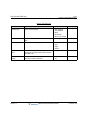
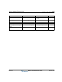
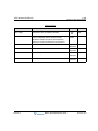
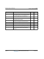
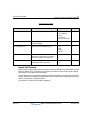
REVISION HISTORY
Release
Date
1.0
07-10
Release 1.0
Documentation Changes
Initial Release
Page No.
--
November 2010
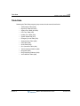
Contents
Chapter 1
Web Service
General - - - - - - - - - - - - - - - - - - - - - - - - - - - - - - - - - - - - - - - PC/Browser - - - - - - - - - - - - - - - - - - - - - - - - - - - - - - - - - Environment for LAN Connection - - - - - - - - - - - - - - - - - - Web Browser Setting - - - - - - - - - - - - - - - - - - - - - - - - - - - Web Home Page - - - - - - - - - - - - - - - - - - - - - - - - - - - - - - - - Browser Access - - - - - - - - - - - - - - - - - - - - - - - - - - - - - - User Guide - - - - - - - - - - - - - - - - - - - - - - - - - - - - - - - - - - Station Program - - - - - - - - - - - - - - - - - - - - - - - - - - - - - - Web Admin & Maintenance - - - - - - - - - - - - - - - - - - - - - - Web Admin Data Modification & Access - - - - - - - - - - - - - - - - Web Admin Data Modification - - - - - - - - - - - - - - - - - - - - Maintenance & Admin ID & Password - - - - - - - - - - - - - - - Password Encryption - - - - - - - - - - - - - - - - - - - - - - - - - - - Web Admin & Maintenance Overview - - - - - - - - - - - - - - - - - -
Chapter 2
1-1
1-1
1-1
1-2
1-3
1-3
1-4
1-5
1-5
1-6
1-6
1-6
1-8
1-9
Web Administration
Pre-Programmed Data - - - - - - - - - - - - - - - - - - - - - - - - - - - - - 2-2
Location Program (PGM 100) - - - - - - - - - - - - - - - - - - - - - - 2-2
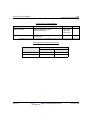
Slot Assignment (PGM 101) - - - - - - - - - - - - - - - - - - - - - - - 2-3
Logical Slot Assignment (PGM 103) - - - - - - - - - - - - - - - - - 2-5
DECT Phone/SIP Phone Max Port (PGM 104) - - - - - - - - - - 2-8
IP Phone Registration (PGM 106) - - - - - - - - - - - - - - - - - - - 2-9
DTIM/SLTM Registration (PGM 107) - - - - - - - - - - - - - - - 2-10
IP Address Plan (PGM 108-109) - - - - - - - - - - - - - - - - - - 2-11
Numbering Plan - - - - - - - - - - - - - - - - - - - - - - - - - - - - - - - - - 2-13
Numbering Plan Type (PGM 110) - - - - - - - - - - - - - - - - - - 2-13
System Numbering Plan (PGM 111) - - - - - - - - - - - - - - - - 2-14
Release 1.0
MBX IP Web Administration Guide
November 2010
Contents
TOC-2
Flexible Station Numbering Plan (PGM 112) - - - - - - - - - - Flexible Numbering Plan (PGM 113-118) - - - - - - - - - - - - CO Group Access Code (PGM 114) - - - - - - - - - - - - - - - - Station Group Number (PGM 115) - - - - - - - - - - - - - - - - - ACD Group Number (PGM 118) - - - - - - - - - - - - - - - - - - Station Port Data - - - - - - - - - - - - - - - - - - - - - - - - - - - - - - - - Station Type (PGM 120) - - - - - - - - - - - - - - - - - - - - - - - - Station Port Attributes (PGM 121-124) - - - - - - - - - - - - - - Flexible Button Assignment (PGM 126) - - - - - - - - - - - - - CTI IP Address Assignment - - - - - - - - - - - - - - - - - - - - - Station Number Data - - - - - - - - - - - - - - - - - - - - - - - - - - - - - Station DN (Directory Number) Assignment (PGM130) - - Station Directory Number Attribules (PGM 131-135 - - - - - Station COS Assignment (PGM 137) - - - - - - - - - - - - - - - Station Auto Dial Attribute (PGM 138) - - - - - - - - - - - - - - Preset Call Forward (PGM 142) - - - - - - - - - - - - - - - - - - - Call Forward (PGM 143) - - - - - - - - - - - - - - - - - - - - - - - - VMIB Attribute (PGM 145) - - - - - - - - - - - - - - - - - - - - - - - Mobile Phone Attribute (PGM 146) - - - - - - - - - - - - - - - - - CO/IP Group Access (PGM 150) - - - - - - - - - - - - - - - - - - Internal Page Group Access (PGM 151) - - - - - - - - - - - - - Command Conference Group Access (PGM 152) - - - - - - CO Line Data - - - - - - - - - - - - - - - - - - - - - - - - - - - - - - - - - - CO Line Attribute (PGM 160-163) - - - - - - - - - - - - - - - - - Incoming CO Attributes (PGM 165-166) - - - - - - - - - - - - - CO Ring Assignment (PGM 167) - - - - - - - - - - - - - - - - - - Incoming CO Normal/DISA Attributes (PGM 168) - - - - - - CO Incoming Alternate Destination (PGM 169) - - - - - - - - CO Outgoing Attribute (PGM 170-171) - - - - - - - - - - - - - - CO Outgoing Alternate Destination (PGM 173) - - - - - - - - CO Outgoing Inter Digit Timer (PGM 174) - - - - - - - - - - - CO DTMF Sending Delay Timer (PGM 175) - - - - - - - - - - CO COS Assignment (PGM 177) - - - - - - - - - - - - - - - - - - -
Release 1.0
MBX IP Web Administration Guide
2-15
2-16
2-21
2-22
2-23
2-24
2-24
2-25
2-29
2-31
2-32
2-33
2-36
2-42
2-43
2-44
2-45
2-47
2-49
2-51
2-52
2-53
2-54
2-55
2-60
2-64
2-66
2-68
2-71
2-75
2-77
2-79
2-81
November 2010
Contents
TOC-3
CO to CO Transfer Attributes (PGM 179) - - - - - - - - - - - - 2-82
CO Group Access Code Attribute (PGM 180) - - - - - - - - - 2-84
Aternate Ring Assignment (PGM 181) - - - - - - - - - - - - - - 2-86
Station Group Data - - - - - - - - - - - - - - - - - - - - - - - - - - - - - - - 2-87
Station Group Assignment (PGM 200) - - - - - - - - - - - - - - 2-88
Station Group Attributes (PGM 201-202) - - - - - - - - - - - - - 2-90
Voice Mail Group Attributes (PGM 203) - - - - - - - - - - - - - - 2-96
Pick Up Group (PGM 204) - - - - - - - - - - - - - - - - - - - - - - - 2-98
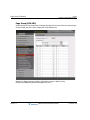
Page Group (PGM 205) - - - - - - - - - - - - - - - - - - - - - - - - 2-100
Command Conference Group (PGM 206) - - - - - - - - - - - 2-102
PTT Group (PGM 208) - - - - - - - - - - - - - - - - - - - - - - - - 2-104
Interphone Group (PGM 209) - - - - - - - - - - - - - - - - - - - - 2-105
Pilot Hunt Group (PGM 210-211) - - - - - - - - - - - - - - - - - 2-107
ACD Group Assignment (PGM 212) - - - - - - - - - - - - - - - 2-109
ACD Group Attributes (PGM 213-214) - - - - - - - - - - - - - 2-112
ACD Group Announcement (PGM 215) - - - - - - - - - - - - - 2-116
System Data - - - - - - - - - - - - - - - - - - - - - - - - - - - - - - - - - - 2-118
System Timers I to III (PGM 220-222) - - - - - - - - - - - - - - 2-119
System Attributes (PGM 223) - - - - - - - - - - - - - - - - - - - - 2-122
System Password (PGM 226) - - - - - - - - - - - - - - - - - - - 2-124
Alarm Attributes (PGM 227) - - - - - - - - - - - - - - - - - - - - - 2-126
External Control Contacts (PGM 228) - - - - - - - - - - - - - - 2-128
Music Source (PGM 229) - - - - - - - - - - - - - - - - - - - - - - - 2-129
RS-232 Port Settings (PGM 230) - - - - - - - - - - - - - - - - - 2-131
Serial Port Function Selections (PGM 231) - - - - - - - - - - 2-132
SMDR Attributes (PGM 232) - - - - - - - - - - - - - - - - - - - - 2-134
System Date, Time (PGM 233) - - - - - - - - - - - - - - - - - - - 2-137
Button LED Flash Rate (PGM 234) - - - - - - - - - - - - - - - - 2-139
PPP Attributes (PGM 235) - - - - - - - - - - - - - - - - - - - - - - 2-144
Mobile Attributes (PGM 236) - - - - - - - - - - - - - - - - - - - - 2-146
Intercom Busy One-Digit Attributes (PGM 237) - - - - - - - 2-147
Dummy Dial-Tone Table (PGM 240) - - - - - - - - - - - - - - - 2-149
Executive/Secretary Assign (PGM 241) - - - - - - - - - - - - - 2-150
Release 1.0
MBX IP Web Administration Guide
November 2010
Contents
TOC-4
Executive-Executive Access (PGM 242) - - - - - - - - - - - - PPTP Attribute - - - - - - - - - - - - - - - - - - - - - - - - - - - - - - Web Access Authorization - - - - - - - - - - - - - - - - - - - - - Table Data - - - - - - - - - - - - - - - - - - - - - - - - - - - - - - - - - - - Toll Exception Tables (PGM 250) - - - - - - - - - - - - - - - - Digit Conversion Tables (PGM 251-252) - - - - - - - - - - - System Time Tables (PGM 253-254) - - - - - - - - - - - - - - LCR Time Table (PGM 255) - - - - - - - - - - - - - - - - - - - - Holiday Time Table (PGM 256) - - - - - - - - - - - - - - - - - - System Speed Table (PGM 257) - - - - - - - - - - - - - - - - - Emergency Code Table (PGM 258) - - - - - - - - - - - - - - - VMIB Announcement Table (PGM 259) - - - - - - - - - - - - Customer Call Routing Table (PGM 260) - - - - - - - - - - - ICLID Route Table (PGM 262) - - - - - - - - - - - - - - - - - - - CLI Conversion Table (PGM 263) - - - - - - - - - - - - - - - - Tone Frequency/Cadence Table (PGM 264) - - - - - - - - - Ring Table (PGM 265) - - - - - - - - - - - - - - - - - - - - - - - - Ring Frequency/Cadence Table (PGM 266) - - - - - - - - - Voice Mail Dialing Table (PGM 269) - - - - - - - - - - - - - - - Tenant Data - - - - - - - - - - - - - - - - - - - - - - - - - - - - - - - - - - Attendant Group Assignment (PGM 270) - - - - - - - - - - - Attendant Group Attributes (PGM 271-272) - - - - - - - - - Night Attendant Group Assignment (PGM 275) - - - - - - - Night Attendant Group Attributes (PGM 276-277) - - - - - Tenant Attributes (PGM 280-281) - - - - - - - - - - - - - - - - Tenant Group Access (PGM 283) - - - - - - - - - - - - - - - - CO Call Restriction (PGM 284-285) - - - - - - - - - - - - - - - Local Call Prefix Tables (PGM 286) - - - - - - - - - - - - - - - Long Distance Call Prefix Tables (PGM 287) - - - - - - - - International Call Prefix Tables (PGM 288) - - - - - - - - - - Tenant Tone Tables (PGM 290) - - - - - - - - - - - - - - - - - Board Data - - - - - - - - - - - - - - - - - - - - - - - - - - - - - - - - - - - ISDN Board Attribute (PGM 300) - - - - - - - - - - - - - - - - - -
Release 1.0
MBX IP Web Administration Guide
2-152
2-153
2-154
2-155
2-156
2-157
2-158
2-160
2-162
2-163
2-164
2-165
2-166
2-168
2-170
2-171
2-173
2-175
2-177
2-179
2-180
2-181
2-186
2-187
2-192
2-195
2-196
2-199
2-200
2-201
2-202
2-207
2-208
November 2010
Contents
TOC-5
ISDN Board Clock Priority (PGM 301) - - - - - - - - - - - - - VOIB/VMIB Board Attribute (PGM 305) - - - - - - - - - - - - Reset Board (PGM 310) - - - - - - - - - - - - - - - - - - - - - - Networking Data - - - - - - - - - - - - - - - - - - - - - - - - - - - - - - Net Basic Attribute (PGM 320) - - - - - - - - - - - - - - - - - - Net Numbering Plan Table (PGM321) - - - - - - - - - - - - - T-Net Data - - - - - - - - - - - - - - - - - - - - - - - - - - - - - - - - - - - T-Net Attribute (PGM 330) - - - - - - - - - - - - - - - - - - - - - CM Attribute (PGM 331) - - - - - - - - - - - - - - - - - - - - - - FoPSTN Attribute (PGM 333) - - - - - - - - - - - - - - - - - - - T-Net Board Attribute (PGM 334) - - - - - - - - - - - - - - - - IP-Phone T-Net Enable (PGM 335) - - - - - - - - - - - - - - - H.323 Data - - - - - - - - - - - - - - - - - - - - - - - - - - - - - - - - - - H.323 Routing Attributes (PGM360) - - - - - - - - - - - - - - H.323 Call Setup Attribute (PGM 361) - - - - - - - - - - - - - H.323 Incoming Attributes (PGM 362) - - - - - - - - - - - - - GateKeeper Attributes (PGM 363) - - - - - - - - - - - - - - - SIP CO Data - - - - - - - - - - - - - - - - - - - - - - - - - - - - - - - - - SIP CO Basic Registration - - - - - - - - - - - - - - - - - - - - - SIP CO Additional Registration - - - - - - - - - - - - - - - - - - SIP CO Codec - - - - - - - - - - - - - - - - - - - - - - - - - - - - - SIP CO User ID Table - - - - - - - - - - - - - - - - - - - - - - - - SIP Station Data - - - - - - - - - - - - - - - - - - - - - - - - - - - - - - SIP Station Basic Registration - - - - - - - - - - - - - - - - - - SIP Station Additional Registration - - - - - - - - - - - - - - - SIP Station Service - - - - - - - - - - - - - - - - - - - - - - - - - - Zone Data - - - - - - - - - - - - - - - - - - - - - - - - - - - - - - - - - - - Zone Attributes (PGM 395) - - - - - - - - - - - - - - - - - - - - Zone RTP Relay Group (PGM 396) - - - - - - - - - - - - - - Inter-Zone Attribute (PGM 397) - - - - - - - - - - - - - - - - - Station Zone Attribute (PGM 399) - - - - - - - - - - - - - - - - SNMP Data - - - - - - - - - - - - - - - - - - - - - - - - - - - - - - - - - - DECT Data - - - - - - - - - - - - - - - - - - - - - - - - - - - - - - - - - - -
Release 1.0
MBX IP Web Administration Guide
2-210
2-211
2-212
2-213
2-213
2-215
2-217
2-218
2-219
2-221
2-223
2-224
2-225
2-225
2-227
2-229
2-230
2-232
2-232
2-234
2-236
2-237
2-238
2-238
2-239
2-241
2-243
2-244
2-246
2-247
2-249
2-251
2-254
November 2010
Contents
TOC-6
DECT Registration - - - - - - - - - - - - - - - - - - - - - - - - - - - DECT Attributes (PGM 491) - - - - - - - - - - - - - - - - - - - - Green Mode - - - - - - - - - - - - - - - - - - - - - - - - - - - - - - - - - - Green Mode Activation - - - - - - - - - - - - - - - - - - - - - - - - Green Mode Time Setting - - - - - - - - - - - - - - - - - - - - - - Initialization - - - - - - - - - - - - - - - - - - - - - - - - - - - - - - - - - - - Initialization (PGM 499) - - - - - - - - - - - - - - - - - - - - - - - - -
Chapter 3
2-254
2-258
2-259
2-259
2-261
2-262
2-262
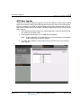
File Upload & Upgrade
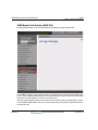
Fle Uploadi - - - - - - - - - - - - - - - - - - - - - - - - - - - - - - - - - - - 3-2
G/W Upgrade - - - - - - - - - - - - - - - - - - - - - - - - - - - - - - - - - - 3-3
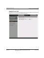
Upgrade Process View - - - - - - - - - - - - - - - - - - - - - - - - - - - 3-5
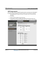
VMIB Prompt Upgrade - - - - - - - - - - - - - - - - - - - - - - - - - - - 3-6
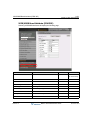
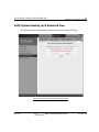
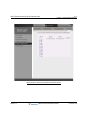
AAFU System Greeting Up & Download View - - - - - - - - - - - - - 3-7
WTIB Base Upgrade - - - - - - - - - - - - - - - - - - - - - - - - - - - - 3-11
MBX IP System Upgrade Process - - - - - - - - - - - - - - - - - - 3-12
Chapter 4
System Management
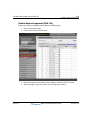
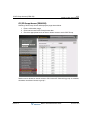
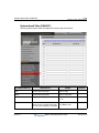
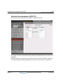
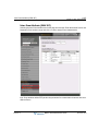
Database - - - - - - - - - - - - - - - - - - - - - - - - - - - - - - - - - - - - - - - 4-2
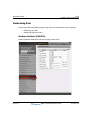
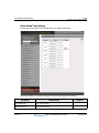
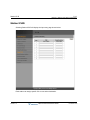
Database Download - - - - - - - - - - - - - - - - - - - - - - - - - - - - - 4-2
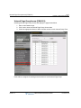
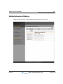
Database Upload - - - - - - - - - - - - - - - - - - - - - - - - - - - - - - - 4-4
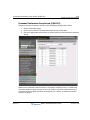
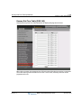
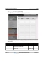
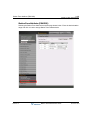
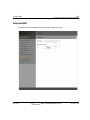
SMDR - - - - - - - - - - - - - - - - - - - - - - - - - - - - - - - - - - - - - - - - - 4-5
Chapter 5
Station User Web Programming
Introduction - - - - - - - - - - - - - - - - - - - - - - - - - - - - - - - - - - - - - - 5-1
Station Port Attributes - - - - - - - - - - - - - - - - - - - - - - - - - - - - - - 5-2
Station DN Attributes - - - - - - - - - - - - - - - - - - - - - - - - - - - - - - - 5-4
Call Forward - - - - - - - - - - - - - - - - - - - - - - - - - - - - - - - - - - - - - 5-6
Preset Call Forward - - - - - - - - - - - - - - - - - - - - - - - - - - - - - 5-7
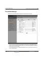
Pre-selected Message - - - - - - - - - - - - - - - - - - - - - - - - - - - - - - 5-8
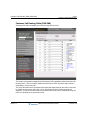
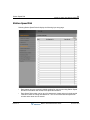
Station Speed Dial - - - - - - - - - - - - - - - - - - - - - - - - - - - - - - - - - 5-9
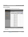
Station Flex Buttons - - - - - - - - - - - - - - - - - - - - - - - - - - - - - - - 5-10
Station ICLID - - - - - - - - - - - - - - - - - - - - - - - - - - - - - - - - - - - - 5-12
Mobile Extension Attributes - - - - - - - - - - - - - - - - - - - - - - - - - 5-13
Internal SMS - - - - - - - - - - - - - - - - - - - - - - - - - - - - - - - - - - - - 5-15
Release 1.0
MBX IP Web Administration Guide
November 2010
Contents
TOC-7
Station Logout - - - - - - - - - - - - - - - - - - - - - - - - - - - - - - - - - - 5-16
Index
Release 1.0
MBX IP Web Administration Guide
November 2010
THIS PAGE INTENTIONALLY LEFT BLANK.
General
1-1
Chapter 1: Web Service
Chapter 1
Web Service
General
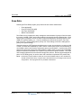
MBX IP incorporates a Web Server located in the MBX IP, which is employed by the system's
Web Service. Using a Web browser to access the system Web Server and the database
managed in a user-friendly environment. In addition to modifying the system database, the
MBX IP Web Admin provides for system file upload, remote upgrade, and database download.
The MBX IP default database includes assignment of a private IP address to the system. This
address (10.10.10.1) may be used to access the system from the LAN. However, a routable IP
address must be assigned for access from a remote location refer to "Browser Access" on
page 1-3.
To access the MBX IP Web Server requires the following:
-
Operating MBX IP system
-
Known IP address assigned in MPB
-
Known TCP port assigned in MPB
-
MBX IP connected to an accessible LAN
-
MBX IP ID & password (Maint, Admin, User), where applicable
PC/Browser
-
MS Internet Explorer (IE) 5.5 is recommended.
-
Windows PC, containing at least 32MB RAM free (64MB or more RAM is
recommended)
-
Network Interface Card (NIC).
Environment for LAN Connection
Release 1.0
-
IEEE 802.3, 10/100 Base T
-
Static/DHCP addressing
-
Firewall, requires Network Administrator to allow access.
-
Remote access requires a routable public/private IP address for the MBX IP system
Web server (must be assigned to the system prior to access).
MBX IP Web Administration Guide
November 2010
General
1-2
Chapter 1: Web Service
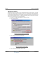
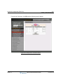
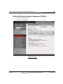
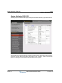
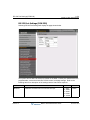
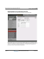
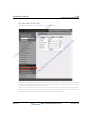
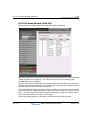
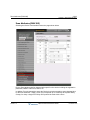
Web Browser Setting
Web browsers may store (cache) a copy of the MBX Web pages in cache memory. The Web
browser may use these copies to provide a "quick view". If the Web page has been Saltered
by data entered in Station Admin or a file upgrade, the cached copy will be out-of-date and could
cause unexpected system operation. To assure proper page views and data entry, the browser
can be set to eliminate the use of the cached pages:
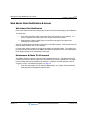
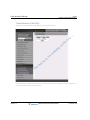
1. On your PC, run MS Internet Explore 5.5 and click "Tools."
2. Click "Internet Options."
MS Internet Explore Options General Menu
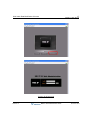
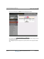
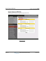
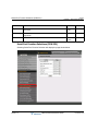
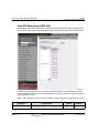
3. Click “Settings” in Temporary Internet files.
MS Internet Explore Settings Menu
4. Check “Every visit to the page” and click “OK.”
Release 1.0
MBX IP Web Administration Guide
November 2010
Web Home Page
1-3
Chapter 1: Web Service
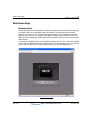
Web Home Page
Browser Access
During initialization, a default database is established. While the system will function employing
the defaults, there are several data entries, which MUST be completed to assure proper
operation of the system. The system employs the Country Code to establish tone and gain
plans specific to the country. In addition, the MPB IP address, sub-net mask and Router IP
address must be assigned for proper external IP call operation, Remote services, and Remote
Admin access.
In the browser ‘ADDRESS’ field, enter the MPB IP address and TCP port. Select GO; the Web
server returns the MBX IP Web Services Home page. On the Home page, one of two services
may be selected, the brief User Guide, Station Program or Admin & Maintenance.
MBX IP Home Page
Release 1.0
MBX IP Web Administration Guide
November 2010
Web Home Page
1-4
Chapter 1: Web Service
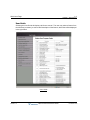
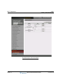
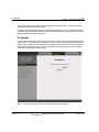
User Guide
Selecting the User Guide will display a brief user manual. The user may select a feature from
the left frame (as shown); to select a brief description of the feature, which then will be displayed
in the right frame.
User Guide
Release 1.0
MBX IP Web Administration Guide
November 2010
Web Home Page
1-5
Chapter 1: Web Service
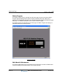
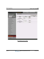
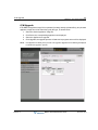
Station Program
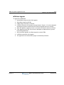
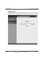
If the Station Program item is selected from the Home page, the user receives the Station
Program displays starting with the Station Program password Web page. Note that if a
password is not assigned for the station, the user will not be able to log in to the Station Program
Web page. For detailed descriptions, refer to section ‘Station Program’
If the Station Program is selected from the Home page, the Station Program will display, as
described further in the following section.
Station Password
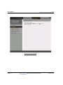
Web Admin & Maintenance
If the Admin & Maintenance item is selected from the Home page, the Admin & Maintenance
manual will display, as described further in the following section.
Release 1.0
MBX IP Web Administration Guide
November 2010
Web Admin Data Modification & Access
1-6
Chapter 1: Web Service
Web Admin Data Modification & Access
Web Admin Data Modification
Each of the system’s data entry Web pages includes a frame for data display and modification.
To modify data:
1. Click in the data field; either a drop-down menu will appear for entry selection, or a
cursor will appear in the field for the user to type in the data required.
2. When finished, click the SAVE button to send the new page to the system and
including the modified data.
Some of the Web pages include blue colored text in the table headers. Selecting this text will
order the table based on the column selected.
In some cases, where mentioned, it may be necessary to reset the system. The system can
be reset manually as described in the MBX IP Hardware & Installation Guide or by selecting the
Reset System button on the Initialization Web page.
Maintenance & Admin ID & Password
The MBX IP System supports a multi-level ID & password structure. The Maintenance ID &
Password controls the access rights of the Admin and User level id & passwords. It is highly
recommended that an ID & password be assigned. In addition, the Web password can be
encrypted, refer to "Password Encryption" on page 1-8.
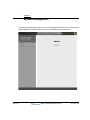
1. From the Home page, click on Admin & Maintenance, the System ID and password
Web page will be displayed as shown below:
Release 1.0
MBX IP Web Administration Guide
November 2010
Web Admin Data Modification & Access
1-7
Chapter 1: Web Service
System ID & Password
Release 1.0
MBX IP Web Administration Guide
November 2010
Web Admin Data Modification & Access
1-8
Chapter 1: Web Service
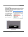
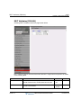
Password Encryption
When enabled, the MBX IP can implement decryption of a password employing RC-6 block
encryption (PGM223).The MBX IP employs a Sun Java Virtual Machine applet to implement
AES encryption. The PC entering the Password must have a JAVA Virtual Machine and the
JRE (Java Runtime Environment) Explorer option enabled to properly handle encrypted
passwords. The Sun JVM is downloaded from the Java home page (www.java.com). Once
downloaded, execute the downloaded file.
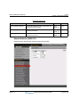
To enable the Explorer JRE option:
1. From the Explorer menu select
Internet Options>Advanced.
2. Click the checkbox to activate the
“Use JRE….” Option.
3. After Restarting the computer,
access the MBX IP Web ID &
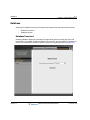
Password page; the Applet Vertical
Pwd started message will display in
the bottom-left corner of the screen to
indicate password encryption is active
(shown in the following graphic).
Web Admin Login Screen
Release 1.0
MBX IP Web Administration Guide
November 2010
Web Admin & Maintenance Overview
1-9
Chapter 1: Web Service
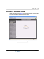
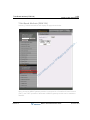
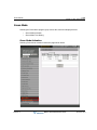
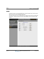
Web Admin & Maintenance Overview
In the Web Admin initial screen on page 1-8, enter the password and click on the Login button
to access the MBX IP Admin & Maintenance Main Page below:
Admin & Maintenance Main Page
Release 1.0
MBX IP Web Administration Guide
November 2010
Web Admin & Maintenance Overview
1-10
Chapter 1: Web Service
Based on the password entered, access to database items and maintenance functions is
determined. The Admin & Maintenance Main Page is comprised of three sections:
•
Menu bar - Upper frame
•
Web site directory & navigation section - Left frame
•
Info and Entry section - Central frame
Items in the Menu bar are mouse-clickable for selections of:
Release 1.0
•
Administration -access to system database
•
File Upload & Remote Upgrade -permits upload of operating files to the MBX IP
system and board.
•
Maintenance -permits databases to be downloaded, including all data.
MBX IP Web Administration Guide
November 2010
2-1
Chapter 2: Web Administration
Chapter 2
Web Administration
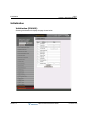
To enter the system database, select the MBX IP Administration item in the menu bar. The
Administration Navigation frame will be displayed on the left.
Admin Menu
Release 1.0
MBX IP Web Administration Guide
November 2010
Pre-Programmed Data
2-2
Chapter 2: Web Administration
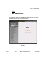
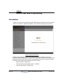
Pre-Programmed Data
Selecting a Pre-Programmed Data program group will display the sub-menus shown and
described in the following sections.
•
•
•
•
•
•
•
Location Program - PGM 100
Slot Assignment - PGM 101
Logical Slot Assignment - PGM 103
DECT/IP/SIP Max Port - PGM 104
IP-Phone Registration - PGM 106
DTIM/SLTM Registration - PGM 107
IP Address Plan - PGM 108-109
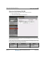
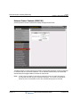
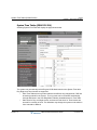
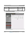
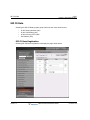
Location Program (PGM 100)
Selecting Location Program will display the following Input Entry page:
Under Location Program, the country is identified using international dial codes (Nation Code).
A 24-character Site Name may be defined. This information is used to set gain, frequencies and
other system characteristics specific to the country and regional regulatory requirements. The
Site Name is primarily useful for the installer/programmer as a reference to the customer.
Release 1.0
MBX IP Web Administration Guide
November 2010
Slot Assignment (PGM 101)
2-3
Chapter 2: Web Administration
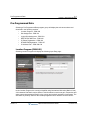
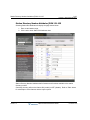
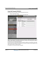
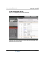
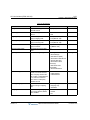
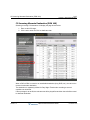
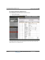
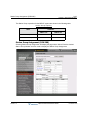
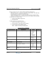
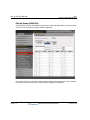
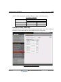
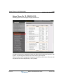
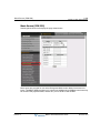
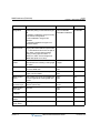
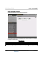
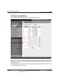
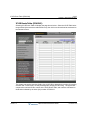
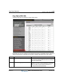
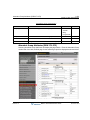
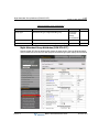
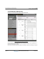
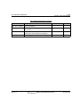
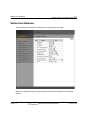
Slot Assignment (PGM 101)
Selecting Slot Assignment will display the following page:
Release 1.0
MBX IP Web Administration Guide
November 2010
Slot Assignment (PGM 101)
2-4
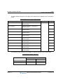
Chapter 2: Web Administration
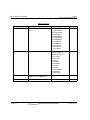
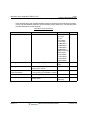
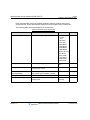
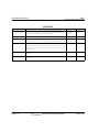
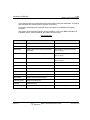
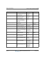
ATTRIBUTE
DESCRIPTION
Slot No.
The slot number -0: The virtual slot for AAFU or VOIU in MPB
1: DSIU slot on MPB
2-18: The real slot no.
19-56: Slot no for MBX IP Gateway(DTIM/SLTM)
88: The virtual slot for SIP Phone
99: The virtual slot for proprietary phone(IP Phone or Phontage)
Logical No.
Display logical number of device
Type
Display the board type. Select the board type to add new board.
Connection
Display the board connection status
No. of Port
Display the port number of board
State
Display the device status on board
MAC Address
Display the MAC address of gateway
IP Address
Display the IP Address of board or gateway
Version
Display the version of board or gateway
CPU
Display the CPU type of board or gateway
Release 1.0
MBX IP Web Administration Guide
November 2010
Logical Slot Assignment (PGM 103)
2-5
Chapter 2: Web Administration
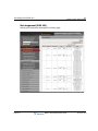
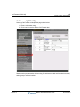
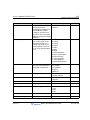
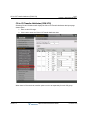
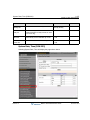
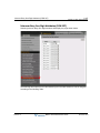
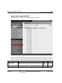
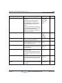
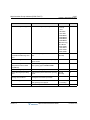
Logical Slot Assignment (PGM 103)
Selecting Logical Slot Assignment and clicking COL at the top of this page will display the
following page:.
Logical Slot Assignment of CO Board
Release 1.0
MBX IP Web Administration Guide
November 2010
Logical Slot Assignment (PGM 103)
2-6
Chapter 2: Web Administration
From the top of this page, click STA and the following page will display.
Logical Slot Assignment of Station Board
Release 1.0
MBX IP Web Administration Guide
November 2010
Logical Slot Assignment (PGM 103)
2-7
Chapter 2: Web Administration
From the top of this page, click VMIB and the following page will display:
Logical Slot Assignment of VMIB Board
The CO/Station/VMIB logical order can be changed by adding a new board, deleting a board or
re-arranging the slot order.
After changing the logical slot assignment, the system should be reset to apply the updated
order.
Release 1.0
MBX IP Web Administration Guide
November 2010
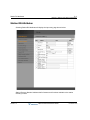
DECT Phone/SIP Phone Max Port (PGM 104)
2-8
Chapter 2: Web Administration
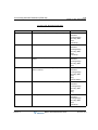
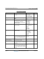
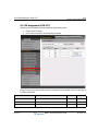
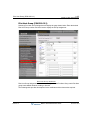
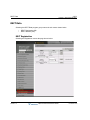
DECT Phone/SIP Phone Max Port (PGM 104)
Selecting DECT/IP/SIP will display the following page:
The DECT, Proprietary Phone (IP Phone or Phontage) and SIP Phone number to be registered
can be assigned. After making the necessary updates, reset the system to apply the changes.
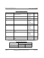
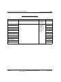
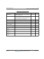
Maximum Port Assignment Attributes
ATTRIBUTE
DESCRIPTION
DEFAULT
Maximum Number of DECT
MAX No of DECT that can be registered to the System.
8
Maximum Number of IP Phone
MAX No of IP Phone that can be registered to the System.
32
Maximum Number of SIP Phone
MAX No of SIP Phone that can be registered to the System.
32
Release 1.0
MBX IP Web Administration Guide
November 2010
IP Phone Registration (PGM 106)
2-9
Chapter 2: Web Administration
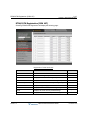
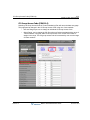
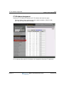
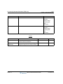
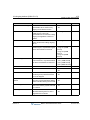
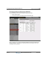
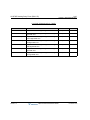
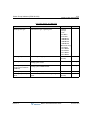
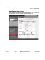
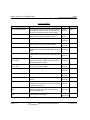
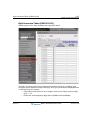
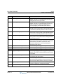
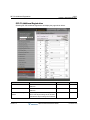
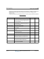
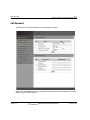
IP Phone Registration (PGM 106)
Selecting IP-Phone Registration will display the following page:
When the desired Index is selected on the screen, the range is shown above (ex.,
[1-50],[51-100],[101-150]).
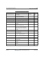
Registration Table Attributes
ATTRIBUTE
Release 1.0
DESCRIPTION
DEFAULT
Index
The index of theIP phone
-
MAC Address
MAC Address of IP phone registered
-
ID
ID of Phontage registered
-
Password
Password of Phontage registered
-
Station Number
Displays the station number if IP phone/Phontage is registered
-
IP Address
Displays the IP Address of the IP phone/Phontage
-
Firewall IP Address Displays the Firewall IP Address of the IP phone/Phontage
-
Type
Displays the model name of the IP phone/Phontage
-
RTP Security
Enable or disable RTP Security of the IP phone
-
State
Displays the connection status of the IP phone/Phontage
-
Mode
Displays the mode of the IP phone/Phontage
-
Version
Displays the version of the IP phone/Phontage
-
MBX IP Web Administration Guide
November 2010
DTIM/SLTM Registration (PGM 107)
2-10
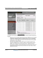
Chapter 2: Web Administration
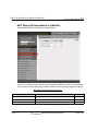
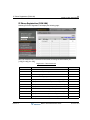
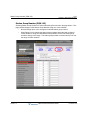
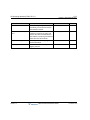
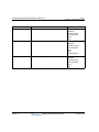
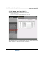
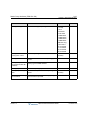
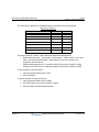
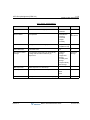
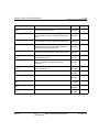
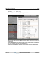
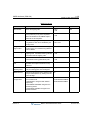
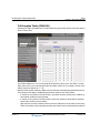
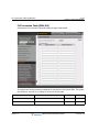
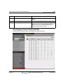
DTIM/SLTM Registration (PGM 107)
Selecting DTIM/SLTM Registration will display the following page:
Registration Table Attributes
ATTRIBUTE
Release 1.0
DESCRIPTION
DEFAULT
Slot No.
Slot number of DTIM/SLTM
-
MAC Address
MAC Address of gateway
-
IP Address
Displays the IP Address of the gateway
-
Firewall IP Address
Displays the Firewall IP Address of the gateway
-
RTP Security
Enables or disables RTP Security of the gateway
-
Type
Displays the gateway type
-
State
Displays the connection status of the gateway
-
Mode
Displays the mode of the IP phone/Phontage
-
Version
Displays the version of the IP phone/Phontage
-
MBX IP Web Administration Guide
November 2010
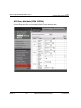
IP Address Plan (PGM 108-109)
2-11
Chapter 2: Web Administration
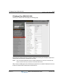
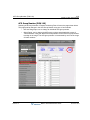
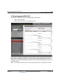
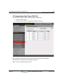
IP Address Plan (PGM 108-109)
Selecting IP Address Plan will display the following page:
The System IP Address Plan sets several IP addresses including the IP address required for
external VoIP calls and the IP address for the router.
NOTE:
The IP and Router addresses must be routable IP addresses for access to an external VoIP
network, remote access by an IP Phone and remote Web access.
When used, the VOIB (Voice Over IP Board) must also have a routable IP address for access
to/from an external VoIP network and a remote device.
Release 1.0
MBX IP Web Administration Guide
November 2010
IP Address Plan (PGM 108-109)
2-12
Chapter 2: Web Administration
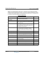
MBX IP can be installed behind a NAPT server, if the NAPT server provides fixed address
translation and port forwarding to the system. In this case, the system will employ the “Firewall
IP address” as the fixed IP address for communication with remote devices. This address must
be assigned as the MFIM address in the remote device.
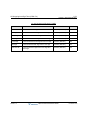
System IP Address Plan
ATTRIBUTE
DESCRIPTION
DEFAULT
IP Address
Public IP Address required for remote user and external
VoIP network access (IPv4 format).
10.10.10.1
Subnet Mask
--
255.255.255.0
Router IP Address
IP Address of router for external network (WAN/IP)
access. Required for shared voice and data LAN and
remote Web access.
10.10.10.254
Firewall IP Address
When the system is installed behind a NAPT server, the
fixed IP Address provided by the NAPT server must be
assigned in this field. Also, use this IP address for the
MFIM address in remote devices.
--
DNS IP Address
IP Address of Domain Name Server, which MBX IP will
use to resolve URLs to an IP address. The DNS
provides the resolution after receiving the name from
Vertical.
--
H.323 Port (0-9999)
H.323 UDP Port
1720
SIP Port (0-9999)
SIP UDP Port
5060
DHCP Usage
If this field is set to "ON", the system obtains the
IP-address from the DHCP Server when it is booting.
Off
Diffserv (0-63)
Diff-Serv pretag value
4
MAC Address
Display the MAC Address of MPB
IPKTS Protocol Port
Display UDP Port for communicating between MPB and
Boards (or, IP Phone)
5588
Private Subnet Mask
Private Subnet Mask
-
Application Release Version Display system version
-
Application Release Date
Display the released date of system software
-
Boot Version
Display system boot version
-
Boot Release Date
Display the released date of system boot
-
Release 1.0
MBX IP Web Administration Guide
November 2010
Numbering Plan
2-13
Chapter 2: Web Administration
Numbering Plan
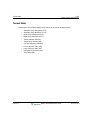
Selecting the Numbering Plan program group displays the following sub-menus:
•
Numbering Plan Type (110)
•
System Numbering Plan (111)
•
Flexible Station Number (112)
•
Feature Numbering Plan (113 / 114 / 115 / 118)
Numbering Plan Type (PGM 110)
Selecting Numbering Plan Type will display the following page:
The MBX IP system provides default Numbering plan set. One of any numbering plans can be
installed or every numbering plan can be cleared.
If numbering plan type 7 (Delete All Numbering) is selected, all numbering codes are deleted.
After deleting, the user should first assign the "System Numbering Plan".
After configuring the system numbering plan, the user can assign the other numbering plan
code. This is useful when the user wants to reconfigure all the numbering codes without default
values.
Release 1.0
MBX IP Web Administration Guide
November 2010
System Numbering Plan (PGM 111)
2-14
Chapter 2: Web Administration
System Numbering Plan (PGM 111)
Selecting System Numbering Plan will display the following page:
To assign a numbering plan code, its type should be matched with a System Numbering Plan,
which consists of a prefix, and additional digits. Prefix means the leading digits of the numbering
plan code, and digits means number of following digits of that Prefix code. The maximum length
of each numbering plan code is 8, and up to 4 additional digits.
When a System Numbering Plan covers numbering plan codes of more than 4 digits, the
preceding digits of the prefix code placed at more than 4th digits from end digit called Master
Prefix Digits; Maximum 3 in the MBX IP-100 system and 5 in MBX IP-300 system Master Prefix
Digits can exist.
NOTE:
A System Numbering Plan conflict is not allowed; if there’s Prefix "1" and more digit 4, then there
cannot be other prefix "10" with more digit 4.
ATTRIBUTE
DESCRIPTION
DEFAULT
Prefix Code
Prefix Code
-
More Digit (0-4)
More Digit
-
Release 1.0
MBX IP Web Administration Guide
November 2010
Flexible Station Numbering Plan (PGM 112)
2-15
Chapter 2: Web Administration
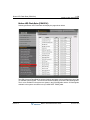
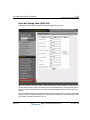
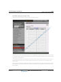
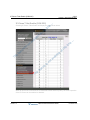
Flexible Station Numbering Plan (PGM 112)
Selecting Flexible Station Number will return the page shown. This page permits changes in
the Station Numbering Plan using one of three methods:
•
Not Use Range Input: use to change an individual station number.
•
Order Range: use to change the station numbers associated with a range of “Order
Numbers” using the “Start Station Number” as the first station number to assign in the
range. The station number is incremented by one over the range of Order numbers.
•
Station Range: use to change station numbers over a range of stations using the “Start
Station Number” as the first station number to assign range. The station number is
incremented by one for each successive station in the range.
•
Station Number Search: use to search station number. If station number is searched, the
station number table is updated and the searched station number is displayed to red.
Selecting a Station Order Range, blue text in the table header, will display the Station
Numbering Plan information for the selected Order Range.
Release 1.0
MBX IP Web Administration Guide
November 2010
Flexible Numbering Plan (PGM 113-118)
2-16
Chapter 2: Web Administration
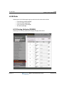
Flexible Numbering Plan (PGM 113-118)
Selecting Feature Numbering of Feature Numbering Plan will return the following page:
Feature dial codes for the system can be assigned using the system Flexible Number Plan.
Feature codes should be matched "System Numbering Plan" and must not conflict. The system
will not update the database until correct data is entered.
Release 1.0
MBX IP Web Administration Guide
November 2010
Flexible Numbering Plan (PGM 113-118)
2-17
Chapter 2: Web Administration
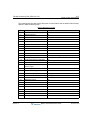
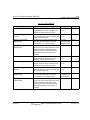
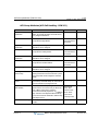
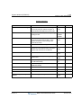
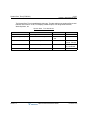
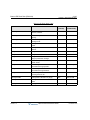
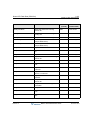
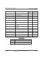
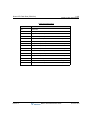
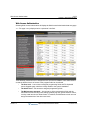
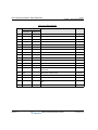
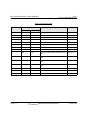
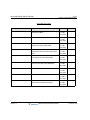
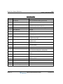
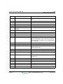
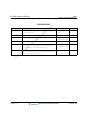
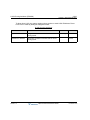
The following table provides a brief description for each feature and the default codes as they
appear in base Numbering Plan 1.
Feature Numbering Codes
NO
Release 1.0
FEATURE NAME
CODE
1
Attendant Call
0
2
Conference Room 1
571
3
Conference Room 2
572
4
Conference Room 3
573
5
Conference Room 4
574
6
Conference Room 5
575
7
Conference Room 6
576
8
Conference Room 7
577
9
Conference Room 8
578
10
Conference Room 9
579
11
Internal Page
543 + 00 (All Call Page), xx (Page Group #)
12
Personal VM Page
544
13
Announcement Page For Attendant
545
14
Page Auto Answer
546
15
Internal Page Answer
(Meet-Me Page)
547
16
External Page
548
17
Internal-External Page All
549
18
Call Forward Register
554 + Type + Destination
19
Pilot Hunt Call Forward Register
514 + Type + Destination
20
Pilot Hunt Call Forward Cancel
515
21
DND Status Change
516
22
DND Delete
517
23
Account Code
550
24
CO Flash
551
25
Last Number Redial
552
26
Station Speed PGM
553
27
Speed Dial
555
28
MWI Register
557
MBX IP Web Administration Guide
November 2010
Flexible Numbering Plan (PGM 113-118)
2-18
Chapter 2: Web Administration
NO
Release 1.0
FEATURE NAME
CODE
29
MWI Answer
558
30
MWI Cancel
559
31
Call Back Register
518
32
Call Back Cancel
519
33
Group Call Pickup
564
34
Direct Call Pickup
7
35
Walking COS
520
36
Call Parking Location
541 + xx (Parking Location 00-49)
37
PGM Mode Access
521
38
Two-Way Record
522
39
VMIB Access
523
40
AME Access
524
41
CO Line Access
888 + CO Line # (001-200: MBX IP-300, 01-80: MBX
IP-100)
42
VM MWI Enable
*8
43
VM MWI Cancel
*9
44
MCID Request
*0
45
Unsupervised Conf Extend
5##
46
PTT Group Access
524 + PTT Group # ( 0-9) + * (Log out)
47
Hot Desk Log In/Log out
525
48
Name Register
526
49
Create Conf Room
527 + Conf. Room #
50
Delete Conf Room
528 + Conf. Room #
51
Wake Up Register
529 + HH:MM
52
Wake Up Cancel
530
53
Temporarily COS Down
531
54
Cancel Temp COS Down
532
55
Password Change
533
56
Inter-Phone Group Access
534
57
Call Wait Request
535
58
Preselected MSG PGM
536
59
Forced Handsfree Call
537
MBX IP Web Administration Guide
November 2010
Flexible Numbering Plan (PGM 113-118)
2-19
Chapter 2: Web Administration
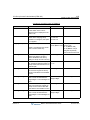
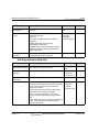
60
Call Based CLIR
NO
Release 1.0
582
FEATURE NAME
CODE
61
CLIR Access
583
62
COLR Access
584
63
Pilot Hunt Call
585
64
Command Call Oneway
581
65
Command Call Conf
580
66
Intrude Register
589
67
Camp On Register
590
68
OHVO Register
591
69
Mobile Num Register
592
70
Mobile CLI Register
593
71
Mobile Access
594
72
Announcement table
670
73
Announcement table and Drop
671
74
System Hold
560
75
Return Held CO
8**
76
Sys Memo
675
77
DISA Tone Service
678
78
All Feature Cancel
679
79
Add Conf Member
680
80
System Alarm Reset
565
81
Fault Alarm Reset
566
82
Door Open
#*1
83
Keypad Facility
##*
84
T-Net Log-In/Out
586
85
Universal Answer
587
86
USB Call Record
588
87
Delete All VM Message
681
88
VM Page Message Record
682
89
Direct VM Transfer
683
90
Loop Key
684
91
Call Log
685
MBX IP Web Administration Guide
November 2010
Flexible Numbering Plan (PGM 113-118)
2-20
Chapter 2: Web Administration
92
NO
Release 1.0
ACD Agent Log-In/Out
500
FEATURE NAME
CODE
93
ACD Agent DND
501
94
ACD Agent Word Mode
502
95
ACD Agent Auto Work
503
96
ACD Agent Auto Answer
504
97
ACD Call Indication
508
98
Non-ACD Call Indication
509
99
ACD Supervisor Group Forward
890
100
ACD Supervisor Night
891
101
ACD Supervisor Holiday
892
102
ACD Supervisor Queued Call Answer 893
103
ACD Supervisor Agent State Check
894
104
ACD Supervisor Silent Monitor
895
105
ACD Supervisor Call Traffic Check
896
106
ACDAnnouncement Play & Check
899
107
Day/Night/Timed Mode Change
513
108
DID/DISA Restriction
685
MBX IP Web Administration Guide
November 2010
CO Group Access Code (PGM 114)
2-21
Chapter 2: Web Administration
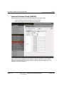
CO Group Access Code (PGM 114)
Selecting CO Group Access Code of Feature Numbering Plan will return the data entry page.
This page permits changes in the CO Group Access Code using one of two methods:
Release 1.0
•
Not Use Range Input: use to change an individual CO Group Access Code.
•
Order Range: use to change the CO Group Access Codes associated with a range of
“Order Numbers” using the “Start CO Group Access Code” as the first number to
assign in the range. The CO group access code is incremented by one over the range
of Order numbers.
MBX IP Web Administration Guide
November 2010
Station Group Number (PGM 115)
2-22
Chapter 2: Web Administration
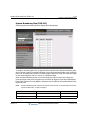
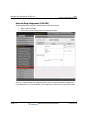
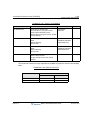
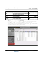
Station Group Number (PGM 115)
Selecting Station Group Number of Feature Numbering Plan will return the page shown. This
page permits changes in the Station Group Number using one of two methods:
Release 1.0
•
Not Use Range Input: use to change an individual station group number.
•
Order Range: use to change the station group numbers associated with a range of
“Order Numbers” using the “Start Station Group Number” as the first station group
number to assign in the range. The station group number is incremented by one over
the range of Order numbers.
MBX IP Web Administration Guide
November 2010
ACD Group Number (PGM 118)
2-23
Chapter 2: Web Administration
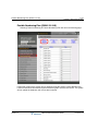
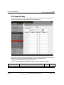
ACD Group Number (PGM 118)
Selecting ACD Group Number of Feature Numbering Plan will return the page shown below.
This page permits changes in the ACD Group Number using one of two methods:
Release 1.0
•
Not Use Range Input: use to change an individual ACD group number.
•
Order Range: use to change the ACD group numbers associated with a range of
“Order Numbers” using the “Start ACD Group Number” as the first ACD group number
to assign in the range. The ACD group number is incremented by one over the range
of Order numbers.
MBX IP Web Administration Guide
November 2010
Station Port Data
2-24
Chapter 2: Web Administration
Station Port Data
Selecting the Station Port Data program group returns the following sub-menus:
•
Station Type - PGM 120
•
Station Port Attribute - PGM 121-124
•
Flexible Button Assignment - PGM 126
•
CTI IP Address
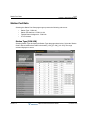
Station Type (PGM 120)
Selecting Station Type will display the Station Type data page shown below. Select the "Station
Order" desired shown above table in the header, [1-50], [51-100], [101-150]. The range
selected displays on screen.
Release 1.0
MBX IP Web Administration Guide
November 2010
Station Port Attributes (PGM 121-124)
2-25
Chapter 2: Web Administration
The SLT sub-type can be assigned a type used by the system to recognize the station’s
capability. Additionally, for DSS consoles the associated station is identified.
STATION TYPE
ATTRIBUTE
DESCRIPTION
DEFAULT
Station Number Station Number
-
Slot (ch#)
-
Displays board name, slot number, and channel (port) index at the board.
Main Type
Displays main type of station
-
Sub Type
Displays the station’s type or select SLT type.
-
DSS Map
DSS associated station number or LIP Serial DSS type.
-
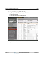
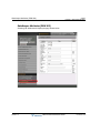
Station Port Attributes (PGM 121-124)
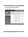
Selecting Station Port Attributes will display the Station Port Attributes page: Enter a valid
station range and click Load to enter Station Port Attributes data.
Release 1.0
MBX IP Web Administration Guide
November 2010
Station Port Attributes (PGM 121-124)
2-26
Chapter 2: Web Administration
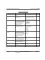
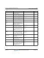
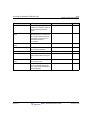
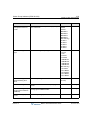
Station Port Attributes define the specific features and functions available to the installed
terminal. Generally, the entry will turn the feature ON (enable) or OFF (disable). Refer to thr
following table for a description of the features and the input required.
ATTRIBUTE
DESCRIPTION
RANGE
DEFAULT
Auto Speak Selection Enables [SPEAKER] activation when a CO/IP,
DSS or other feature button is pressed, no need to
lift handset.
0: Off
1: On
On
Headset Mode
Determines if Speakerphone mode, Headset mode
or Ear Mic Mode will be used.
0: Speaker
1: Headset
2: E-MIC
Speaker
Headset Ring
In Headset mode, this item selects device to
receive incoming ring signals.
0: Speaker
1: Headset
2: Both
Speaker
Group Listening
Enables Group Listen feature, audio is sent to both
the handset and speaker with the handset
microphone active and speakerphone microphone
OFF.
0: Off
1: On
Off
Keyset Admin
Enables station access to the System Database.
0: Disable
1: Enable
Disable
No Touch Answer
Enables No-touch answer; this will automatically
connect transferred calls to the station’s
speakerphone.
0: OFF
1: ON
Off
Howling Tone
Permits Howler tone to be sent to a SLT when left
off-hook.
0: Off
1: On
On
Dummy Terminal
Determines whether a station is used as a Hot
Desk terminal (must be set to "ON").
0: Off
1: On
Off
Port Blocking
If this value is set to ON, Station is blocked so it is
impossible to use that station.
0: Off
1: On
Off
Gain Table Index
Determines Gain Table for each station.
Table 1-Table 3
Table 1
SLT Line Length
This feature is used to distinguish the line length
when the distance between SLT station and SLIB
board is too variable.
(Short: 0km, Long: 0-3km, Far: 3-7.5km)
0: Short
1: Long
2: Far
Short
System Alarm Report
Enable to receive system alarm signal.
0: Disable
1: Enable
Disable
Door Open Access
Enable to use door open feature.
0: Disable
1: Enable
Disable
Release 1.0
MBX IP Web Administration Guide
November 2010
Station Port Attributes (PGM 121-124)
2-27
Chapter 2: Web Administration
ATTRIBUTE
DESCRIPTION
RANGE
DEFAULT
LCD language
Display Mode
Sets the Language used in the Station’s LCD.
00-14
00 (English)
LCD Date Display
Mode
Sets the Station Date display as month/day or
day/month.
1: MMDDYY
0: DDMMYY
DDMMYY
LCD Time Display
Mode
Sets the Time display mode as 12 hour or 24-hour
(military) time.
1: 24 Hour Mode
0: 12 Hour Mode
12 Hour
Backlight Usage
If a station can support LCD backlight, you can set
backlight usage option.
0: Always Off
1: Busy Only
2: Always On
Busy Only
IP-8000 Phone Font
Determines if Times New Roman or Gothic font is
used.
0: Times New
Roman
1: Gothic
Times New
Roman
IP-8000 Phone LCD
Brightness
LIP 8000 Series terminal can adjust LCD
brightness.
01-15
07
Prime Number Button
(1-48)
Among My-DN and several Sub-DNs which are
assigned to station flex buttons, determines the
first-seized DN when the user initiates a call.
If set, the system scans sequentially from FLEX
1-48 and takes the unused and valid flexible button
as prime button.
NOTE: DN buttons on an associated DSS box
cannot be a prime number button.
01-48
01
Zone Number (1-9)
Determines the zone where a station belongs.
1-9
1
Automatic Hold
Enables Auto Hold for the station. With Auto Hold
enabled, the system will place an active external
call on hold if the user presses a CO/IP or DSS
button.
0: Off
1: On
Off
Enblock Dial Mode
If set to All, user-dialed digits are stored at the
Digital Phone until explicitly sent by the user.
When sent, all dialed digits are sent to the system
in a bloc (only available to Digital Phones with soft
keys).
0: Off
1: All
2: On Hook Dialing
Only
Off
Intercom Answer
Mode
Selects Handsfree, Privacy or Tone ring ICM
Signaling mode.
1: Handfree
2: Tone
3: Privacy
Tone
Data Line Security
Disables override and camp-on tones to the station 0: Off
to avoid encountering an error when sending data. 1: On
Release 1.0
MBX IP Web Administration Guide
Off
November 2010
Station Port Attributes (PGM 121-124)
2-28
Chapter 2: Web Administration
ATTRIBUTE
DESCRIPTION
RANGE
DEFAULT
DTMF Confirmation
Tone When Redial
If this value is set to ON, DTMF tone is delivered to
the station user when redialing (Reserved).
0: Off
1: On
Message-Wait
Indication
Determines the way to notify a station of wait
message.
MW Remind
0: N/A
Tone
1: Ring LED
2: MW Remind Tone
3: Ring LED + Tone
Apply Differential
Ring
Determines differential ring mode.
0: All Ring
1: Normal Ring
All Ring
Intercom Differential
Ring ID (0-254)
Sets the intercom differential ring ID (1-4 usually
valid).
000-254
1
CO Differential Ring
ID (0-254)
Sets the CO line differential ring ID (1-4 usually
valid).
000-254
1
Apply Digit
Conversion Table
Determines whether the digit conversion follows
COS of SUB-DN or COS of MY-DN Regardless of
SUB-DN.
0: SUB-DN
1: MY-DN
SUB-DN
Hook Flash When
Transfer
Determines the operation when the user presses
the hook-flash button while transferring a call.
0. Cancel transfer: drops current call and recover
previous call
1. Broker Call: holds current call and recover
previous held call
2. Conference: establishes 3-way conference call.
3. Conference after Broker Call: establishes conf
when hook flash within 2 sec in broker call.
0: Cancel Transfer
1: Broker Call
2: Conference
3: Conference after
Broker Call
Cancel
Transfer
Off-Hook On Paged
When lifting handset while listening to paging msg,
user can make another call or continue to listen.
0: continue to listen to paging message
1: stop listening, seize a DN, and hear dial tone.
User can make a another call.
0: Paged
1: Dial-Tone
Paged
Preferred Line
Answer
Enables Ringing Line Preference for the station.
Calls that ring the telephone are answered by
going off-hook (Reserved).
0: Off
1: On
On
Pick-Up By DSS
Button
This value determines the method of pickup when
pressing DSS button.
0: Disable
1: Group Pickup
2: Direct Pickup
Direct
Pickup
CTI IP Address
CLI IP Address
IP Address
0.0.0.0
ACD Agent Priority
When a station is a memger of an ACD Group, this
value will be used for priority as agent.
01-20
10
Release 1.0
MBX IP Web Administration Guide
On
November 2010
Flexible Button Assignment (PGM 126)
2-29
Chapter 2: Web Administration
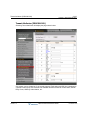
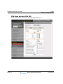
Flexible Button Assignment (PGM 126)
Selecting Flex Button Assignment will display the following page:
1. Enter a valid station range.
2. Click Load to enter Flex button data.
3. Each Flex button for each station can be assigned a function (TYPE) as listed.
4. After selecting the Type for a button, enter the value (as needed).
Release 1.0
MBX IP Web Administration Guide
November 2010
Flexible Button Assignment (PGM 126)
2-30
Chapter 2: Web Administration
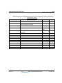
ATTRIBUTE
DESCRIPTION
Range
Default
Type
Select button type from available choices:
- Not Assigned
- Station DSS: assign station DSS button
- CO Number: assign CO line button
- Loop key: assign Loop Key
- CO Group Access: assign CO Group Access Code
- Station Group Number: assign station Group Number
- Dial Number: assign feature code or digits
- Directory Number: assign Directory Number
- Redial: assign [REDIAL] button
- Speed: assign [SPEED] button
- Conference: assign [REDIAL] button
- Mute: assign [MUTE] button
- Call Back: assign [CALLBACK] button
- DND/FWD: assign [DND/FWD] button
- Transfer: assign [TRANSFER] button
- Flash: assign [FLASH] button
- PTT: assign [PTT] button
-
-
Value
Station Number if button is "Station Number" type,
OR
Dial digit if button is "Dial Number" type.
-
-
Ring Option
The Ring Option of Station Number
-
-
Access type
Determines Station Number access type if button is "Station
Number" type.
0 - All call: there is no restriction.
1 - Seize and Dial: Unable to seize only by off-hook when
making outgoing calls even if the button is set to prime
number button.
2 - Incoming only: Unable to make an outgoing call using this
button. Only answering incoming call is allowed.
OR
Button Assignment privilege at the station if button is "Dial
Number" type
-
-
Name
Button Name
-
-
Release 1.0
MBX IP Web Administration Guide
November 2010
CTI IP Address Assignment
2-31
Chapter 2: Web Administration
CTI IP Address Assignment
Selecting CTI IP Address will display the CTI IP Address data input entry page.
Select the 'Station Order' desired shown above table the header, [1-50], [51-100],
[101-150]; the range selected will display.
CTI IP Address defines the PC IP Address to be integrated as first party CTI Application.
Release 1.0
MBX IP Web Administration Guide
November 2010
Station Number Data
2-32
Chapter 2: Web Administration
Station Number Data
Selecting the Station Number Data program group returns the following sub-menus:
Release 1.0
•
Station DN Assignment (130)
•
Station DN Attribute (130-135)
•
COS Assignment (137)
•
Auto Dial Attribute (138)
•
Preset Call Forward (142)
•
Call Forward (143)
•
VMIB Attribute (145)
•
Mobile Extension Attribute (146)
•
CO/IP Group Access (150)
•
Page Group Access (151)
•
Command Group Access (152)
MBX IP Web Administration Guide
November 2010
Station DN (Directory Number) Assignment (PGM130)
2-33
Chapter 2: Web Administration
Station DN (Directory Number) Assignment (PGM130)
1. Enter a valid station range.
2. Click Load to assign DN.
SADN Assignment
Release 1.0
MBX IP Web Administration Guide
November 2010
Station DN (Directory Number) Assignment (PGM130)
2-34
Chapter 2: Web Administration
MADN Assignment
In accordance with its physical characteristics, the station number is divided into My-DN and
Sub-DN.
Release 1.0
•
My-DN is only a role of Single-Assign Directory Number (SADN) and only one My-DN
is assigned to a physical terminal. In the MBX IP system, the scope of the station
number used for My-DN is predefined – the station bin index from 1 to 324 for MBX
IP-300, from 1 to 108 for MBX IP-100. Station number with station bin index greater
than My-DN’s bin index is Sub-DN.
•
Sub-DN is used for MADN or SADN. MADN can have 10 different stations as its
members but SADN has only 1 member. In addition to, Sub-DN, which is used for
SADN, can be configured as a hot-desk agent number. If Sub-DN is used as a
hot-desk agent, the station is not allocated explicitly for Sub-DN member. Only when a
terminal login to Hot Desk with Sub-DN, Sub-DN has the terminal’s station number
(My-DN) as its member.
MBX IP Web Administration Guide
November 2010
Station DN (Directory Number) Assignment (PGM130)
2-35
Chapter 2: Web Administration
Station DN Assignment
ATTRIBUTE
DESCRIPTION
DEFAULT
Index
The index of DN Member
-
Station Number
My-DN station number to be assigned as DN member
-
Flexible Button No.
The button number to assign DN to My-DN station
-
Ring Option
Ring option for DN
-
Access Type
Access type of DN.
0. All call: there is no restriction.
1. Seize and Dial: Unable to seize only by off-hook when making
outgoing call even if the button is set to prime number button.
2. Incoming only: Unable to make an outgoing call using this button.
Only answering incoming call is allowed.
-
Use DN as
Prime-DN
Select button for assigning the DN as Prime-DN
-
Release 1.0
MBX IP Web Administration Guide
November 2010
Station Directory Number Attribules (PGM 131-135
2-36
Chapter 2: Web Administration
Station Directory Number Attribules (PGM 131-135
Selecting Station DN Attributes will display the page shown below..
1. Enter a valid station range.
2. Click Load to enter Station DN Attributes data.
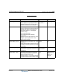
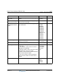
Station Directory Number Attributes define features and functions available to the station
directory number.
Generally, the entry will turn the feature ON (enable) or OFF (disable). Refer to Table below
for a description of the features and the input required.
Release 1.0
MBX IP Web Administration Guide
November 2010
Station Directory Number Attribules (PGM 131-135
2-37
Chapter 2: Web Administration
ATTRIBUTE
DESCRIPTION
RANGE
DEFAULT
Station Name
Enables user name entry. The name is
displayed on the LCD of Digital Phones.
Max 16 Chars
--
Tenant Group
Specifies tenant group for station.
1-9 (MBX IP-300)
1-5 (MBX IP-100)
1
Digit Conversion
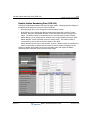
Table
Specifies Digit conversion table for station.
1-9
1
Password
Password is employed to control access to
the system resources and facilities. Walking
COS, CO/IP Group access DISA callers and
certain Call Forward types may require the
input of a valid password.
0-12 digits
--
Busy Service
When a station is busy and if another new call
is arrived, station treats this new call following
this option.
0: Busy Tone
1: Camp-on
2: Call Wait
3: Pilot Hunt
Busy Tone
Charge Mode
If "Free", the intercom call is not printed/saved
to SMDR even though "ICM CALL" SMDR is
enabled.
If "Report", the intercom call is included to
SMDR according to the ICM CALL SMDR
Attributes.
0: Free
1: Report
Report
Smdr Dialed Digit
Hidden
If enabled and station makes an outgoing call,
then dialed digit in SMDR data can be shown
with hidden digit rule by SMDR attribute. If
disabled, all dialed digits will be displayed.
0: Disable
1: Enable
Disable
Hot Desk Agent
Number
Permits a station number as Hot Desk agent
number. To make this feature effective, station
number must be S-DN & SADN.
0: Off
1: On
Off
Time Table Index
Specify Time Table index for station.
1-9, None
None
Forced Handsfree
Access
When placing an intercom call, a user can
change the ICM signaling mode, Tone Ring to
Hands free answer mode or Hands free
answer to Tone Ring mode.
0: Disable
1: Enable
Disable
Forward Access
Enables Call Forward to be activated by the
station.
0: Disable
1: Enable
Enable
Release 1.0
MBX IP Web Administration Guide
November 2010
Station Directory Number Attribules (PGM 131-135
2-38
Chapter 2: Web Administration
ATTRIBUTE
DESCRIPTION
RANGE
DEFAULT
Offnet-Forward
Access
A station must be allowed Off Net Fwd to
forward external incoming calls outside the
system or otherwise establish a CO-to-CO
connection
0: Disable
1: Enable
Enable
DND Access
Enables DND to be activated by the station.
0: Disable
1: Enable
Enable
Intrusion Access
Enables intrusion to gain access to an active
call.
0: Disable
1: Enable
Disable
Mobile Extension
Access
Enables mobile extension ability.
0: Disable
1: Enable
Enable
Hook Flash Mode
Determines the operation when the SLT user
presses the hook-flash button during a
conversation.
0. FLASH NORMAL: Hook Flash can be
detected. In addition, it will be operated
normal case flow.
1. FLASH IGNORE: Hook Flash cannot be
detected. All of hook flash will be ignored at
any time.
2. FLASH DROP: When Hook Flash is
detected, the line will be disconnected.
3. HOLD RELEASE: Drop the holding line if
system detects Hook Flash and then
On-Hook during dialing state.
0: Flash Normal
1: Flash Ignore
2: Flash Drop
3: Hold Release
Flash Normal
Auto Pickup
If a group member phone is ringing, another
member of the Group can Pick-Up a call
ringing at the member station by simply going
“Off-hook”.
0: Disable
1: Enable
Disable
CO Queue Access
Enables CO Queuing
0: Disable
1: Enable
Enable
Conference Access
Enables Conference call
0: Disable
1: Enable
Enable
Wake-up Access
Enables Wake-up Alarm feature
0: Disable
1: Enable
Enable
Station Call Back
Access
Enables call back feature when a called
station is busy.
0: Disable
1: Enable
Enable
ACNR Access
Enables ACNR feature
0: Disable
1: Enable
Enable
Release 1.0
MBX IP Web Administration Guide
November 2010
Station Directory Number Attribules (PGM 131-135
2-39
Chapter 2: Web Administration
ATTRIBUTE
DESCRIPTION
RANGE
DEFAULT
Absence Notice
Access
Enables Absence notice feature
0: Disable
1: Enable
Enable
Call Wait Access
Enables to leave a call wait when a called
station does not answer or is in DND state.
0: Disable
1: Enable
Enable
Camp-on Access
Enables camp-on feature.
0: Disable
1: Enable
Enable
Voice Over Access
Enables voice over feature.
0: Disable
1: Enable
Disable
Rejection of Voice
Over
Enable of rejection authority about voice over
feature
0: Disable
1: Enable
Disable
Prepaid Call Usage
Enables prepaid call
0: Disable
1: Enable
Disable
Keypad Facility
Usage
Enable keypad facility
0: Disable
1: Enable
Disable
Speed Access
Enables station speed dial bin access
authority
0: Disable
1: Enable
Enable
Page Access
Permits station to make page
0: Disable
1: Enable
Enable
Meet-Me Access
Enables "Meet Me" feature when there is a
page made.
0: Disable
1: Enable
Enable
CO Call Duration
Restrict
Restricts CO Call Duration to station.
0: Disable
1: Enable
Disable
SLT Block Back Call
When SLT extension attempts to transfer a
CO call to a CO line it is blocked and the call
is released.
0: Disable
1: Enable
Disable
Pilot Hunt Ring
Permits station to receive pilot hunt ringing.
0: Disable
1: Enable
Enable
ACR User
Sets Anonymous Call Restrict service.
0: Off
1: On
Off
Wake-Up
Time(HHMM)
Sets the wake-up time
HH:MM
--
Repeat Wake-up
Enables daily repeating alarm
0: Off
1: On
Off
Branch Line/Bridge
Line Mode
Enables branch line feature (to restrict a
conference call by pressing {DN} button in
use).
0: Off
1: On
Off
Release 1.0
MBX IP Web Administration Guide
November 2010
Station Directory Number Attribules (PGM 131-135
2-40
Chapter 2: Web Administration
ATTRIBUTE
DESCRIPTION
RANGE
DEFAULT
Auto Privacy
Enables auto privacy feature (to restrict the
intrusion/call-wait/camp-on/OHVA at a busy
station).
0: Off
1: On
Off
DID/DISA Restriction
If set, incoming DID and DISA calls to DN are
restricted.
0: Off
1: On
Off
CLIP Display
CLIP (Calling Line Identification
Presentation), an ISDN service, sends the
number of the calling party to the system in
the call SETUP message. If enabled, the
number will be shown in the Digital phone
LCD.
0: Off
1: On
On
COLP Display
COLP (Connected Line Id Presentation), an
ISDN service, sends the number of the
answering party to the system in the call
CONNECT message. If enabled, the number
will be shown in the Digital Phone LCD.
0: Off
1: On
Off
CLI/Redirect
When an incoming ISDN call is redirected, the
call SETUP message will contain an original
and redirected CLI. This selection
determines if the Digital Phone will display the
original or redirected CLI number.
0: CLI
1: Redirect
CLI
CLIR When Outgoing CLIR (Calling Line Identification Restriction),
an ISDN service, removes calling party ID
sent from the PSTN to the called party with a
RESTRICT instruction in the SETUP
message. If enabled, the system will send
RESTRICT instruction to the PSTN when an
outgoing ISDN call is placed.
0: Off
1: On
Off
COLR When
Incoming Answer
COLR (Connected Line Id Restriction), an
ISDN service, removes connected party ID
sent from the PSTN to the calling party with a
RESTRICT instruction in the CONNECT
message. If enabled, the system will send the
restrict instruction to the PSTN when the
station answers an ISDN call.
0: Off
1: On
Off
CLI Number
When not restricted (btn 4 & 5 above), entry is
added to the number sent in the ISDN call
SETUP or CONNECT message in place of
the station number.
24 digits
Release 1.0
MBX IP Web Administration Guide
November 2010
Station Directory Number Attribules (PGM 131-135
2-41
Chapter 2: Web Administration
ATTRIBUTE
DESCRIPTION
RANGE
DEFAULT
Call Forward
CLI/Redirect
When an incoming ISDN call is forwarded by
the ISDN, the call SETUP message will
contain an original and redirected CLI. This
selection determines if the Digital Phone will
display the original or redirected number.
0: CLI
1: Redirect
CLI
Ignore Caller’s CLIR
option
When a call with CLIR option is received,
option will be ignored and display CID.
0: Off
1: On
Off
Mobile Extension CLI When mobile extension makes a call, CLI is
determined by this option.
0: Caller No
1: Mobile Station No
2: Caller No + Mobile Staton No)
0: Caller No
1: Mobile Sta No
2:Caller+Mobile Sta
Caller No
Long CLI 1
If CLI type of outgoing CO line is set to 1,
Long CLI 1 is sent.
24 digits
--
Long CLI 2
If CLI type of outgoing CO line is set to 2,
Long CLI 2 is sent.
24 digits
--
Long CLI 3
If CLI type of outgoing CO line is set to 3,
Long CLI 3 is sent.
24 digits
--
CLI Name Display
If CLI type of outgoing CO line is set CLI
Name Display, CLI Name is sent.
0: Off
1: On
Off
Station No. Hidden
If this is set to ON, station number is not
displayed at calling or called party LCD.
This selection determines if the Digital Phone
will display the Station number.
0: Off
1: On
Off
Call Transfer CLI
When a STA makes a transfer call, the call
SETUP message will contain a transferor or
transferred CLI.
Transferor
Transferred
Transferor
Release 1.0
MBX IP Web Administration Guide
November 2010
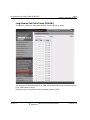
Station COS Assignment (PGM 137)
2-42
Chapter 2: Web Administration
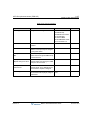
Station COS Assignment (PGM 137)
Selecting COS Assignment will display the page shown below.
1. Enter a valid station range.
2. Click Load to enter the Station COS data.
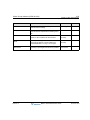
All stations are assigned a Class-of-Service (COS), which determines the ability of the user to
dial certain types of calls. Separate COS assignments are made for Day, Night and Timed Mode
operation. As a default all stations are assigned with a Station COS of 1 for all modes, no
restrictions.
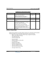
STATION COS
RESTRICTIONS
0
Intercom and Emergency number calls are allowed. Incoming and transferred calls are
allowed.
1
No restrictions are placed on dialing.
2-15
Release 1.0
Assignments in each toll exception table are monitored for allow and deny numbers.
- If a table has no entries, no restrictions are applied.
- If there are only Deny entries, restrictions are provided as Deny only.
- If there are only Allow entries, restrictions are provided as Allow only.
- If there are both Allow and Deny entries, the Deny entries are searched. If dialed number
matches Deny entry, call is restricted; if no match is found call is allowed.
MBX IP Web Administration Guide
November 2010
Station Auto Dial Attribute (PGM 138)
2-43
Chapter 2: Web Administration
Station Auto Dial Attribute (PGM 138)
Selecting Auto Dial Attribute will display the Station page shown below.
1. Enter a valid station range.
2. Click Load to enter the Station Auto Dial Attribute.
When a station goes off-hook (lifts handset or presses [SPEAKER] button), the system normally
provides an intercom dial tone.
In place of the dial tone, the station can be programmed to Auto-Dial Digit the preprogrammed
(max 16) digits. If configured, and if no digit is entered within the "auto dial pause time", is then
the system will dial the "Auto-Dial-Digit" automatically.
ATTRIBUTE
Release 1.0
DESCRIPTION
DEFAULT
Auto Dial Digit
Digits will be dialed automatically
Auto Dial Digit
Auto Dial Pause Time
Auto dial pause time
Auto Dial Pause Time
MBX IP Web Administration Guide
November 2010
Preset Call Forward (PGM 142)
2-44
Chapter 2: Web Administration
Preset Call Forward (PGM 142)
Selecting Preset Call Forward will display the page shown below
1. Enter a valid station range.
2. Click Load to enter the Station Preset Call Forward data.
Stations can be programmed so that incoming CO and Intercom calls are forwarded to a preset
station or station group. This allows an external call or internal call to initially ring at a station
and forward to a pre-determined destination.
Preset Forward can be separately assigned Internal Unconditional, Internal Busy, Internal No
Answer, External Unconditional, External Busy or External No Answer preset forwarding to any
station, station group or external number.
As a default, no Preset Call Forward is assigned.
Release 1.0
MBX IP Web Administration Guide
November 2010
Call Forward (PGM 143)
2-45
Chapter 2: Web Administration
Call Forward (PGM 143)
Selecting Call Forward will display the page shown below.
1. Enter a valid station range.
2. Click Load to enter the Station Call Forward data.
Stations can be programmed so that incoming CO and Intercom calls are forwarded to a station,
station group or external number.
Release 1.0
MBX IP Web Administration Guide
November 2010
Call Forward (PGM 143)
2-46
Chapter 2: Web Administration
Station Call Forward
ATTRIBUTE
DESCRIPTION
RANGE
DEFAULT
Forward Type
Specify call forward type.
Not Assigned
0: Not Assigned
1: Unconditional
2: Busy
3: No Answer
4: Busy or No Answer
Forward Number
Specify Call Forward Destination by entering dial
digits.
Max 32 digits
-
Forward Apply Time Specify Call Forward Applying Time
0: All
1: Day
2: Night
3: Timed
All
CFW No-Answer
Timer
Call is forwarded to "Call Forward Destination," if
station does not respond during this "CFW NO
ANS TMR" timer.
( 0-600) sec
15sec
Forward Information
Display
Enables Forward Display Option to check
forward information in idle state.
0: Off
1: On
On
Release 1.0
MBX IP Web Administration Guide
November 2010
VMIB Attribute (PGM 145)
2-47
Chapter 2: Web Administration
VMIB Attribute (PGM 145)
Selecting VMIB Attribute will display the page shown below.
1. Enter a valid station range.
2. Click Load to enter the Station VMIB Attribute Data.
Station VMIB Attributes define VMIB features and functions available to the station directory
number.
Release 1.0
MBX IP Web Administration Guide
November 2010
VMIB Attribute (PGM 145)
2-48
Chapter 2: Web Administration
Station Directory Number Attributes
ATTRIBUTE
DESCRIPTION
RANGE
DEFAULT
VMIB Access
Permits station access to VMIB.
0: Disable
1: Enable
Disable
Prompt Language Index
Selected language type prompt is played to the user
when accessing the VMIB.
1-3
1
Auto-Record Service
When allowed, if user is in conversation with
internal/external users, their conversation will be
automatically recorded. It can be used without two-way
record button.
0: Disable
1: Enable
Disable
Two-Way Record Access
When allowed, the station can activate the Two-way
record feature to record a conversation.
0: Disable
1: Enable
Disable
Two-Way Recording
Destination
It defined location of Two-Way recorded wav files.
When VM Boards, recorded wav files is saved at
internal VM boards. In addition, if assign specific
Phontage and this Phontage is supportable s/w
version, recorded wav files is saved at hard disk of
Phontage program installed PC.
--
VM
Internal
Boards.
VM Message Backup
Phontage Number
When station has new voice mail in VM internal boards,
this information is reported to assigned Phontage
number. In addition, Phontage user can backup these
saved voice mail from VM internal boards to hard disk
of Phontage program installed PC.
--
--
VM Message Backup
Delete Option
When allowed, Phontage user can delete all voice mail
in VM internal boards.
1: Enable
0: Disable
0:Disable
VMIB Message Retrieve
Type
Messages stored in the VMIB may be retrieved in either
a FIFO (first-in-first-out) or LIFO (last-in-first-out) order
based on this entry.
1: FIFO
0: LIFO
LIFO
VMIB New Message No
Displays the number of new messages.
--
--
VMIB Saved Message No
Displays the number of saved messages.
--
--
VM MSG-SMTP Mail
Server Address
SMTP Mail Server Address
--
--
VM MSG-User Mail
Address
User Mail Address
--
--
VM MSG-SMTP Mail
Server ID
SMTP Mail Server ID
--
--
VM MSG – SMTP Mail
Server ID
SMTP Mail Server ID
--
--
--
--
VM MSG – Attach Message attach message or not
Release 1.0
MBX IP Web Administration Guide
November 2010
Mobile Phone Attribute (PGM 146)
2-49
Chapter 2: Web Administration
Mobile Phone Attribute (PGM 146)
Selecting Mobile Phone Attribute will display the page shown below.. Enter a valid station range
and click Load to enter the Station Mobile Phone Attribute Data.
A mobile phone can be used in conjunction with a station. The Mobile phone can access
system resources available to the user’s wired phone and will receive ringing for incoming calls.
The user may be allowed to enable the Mobile extension and define the mobile number.
Release 1.0
MBX IP Web Administration Guide
November 2010
Mobile Phone Attribute (PGM 146)
2-50
Chapter 2: Web Administration
Mobile Phone Attribute
ATTRIBUTE
DESCRIPTION
RANGE
EXT.ID
Mobile phone index
--
Mobile enable
Enable mobile extension ability
0: OFF (default)
1: ON
Number
Mobile extension number
Max 24 digits
CLI
Mobile extension CLI number
Max 24 digits
Mobile Service Mode
Select apply mobile service to ALL call or CLI1-CLI5.
ALL Call OR,
Service CLI only
Mobile Service CLI (1-5)
CLI for Mobile Service
--
Release 1.0
MBX IP Web Administration Guide
November 2010
CO/IP Group Access (PGM 150)
2-51
Chapter 2: Web Administration
CO/IP Group Access (PGM 150)
Selecting CO/IP Group Access will display the page shown below..
1. Enter a valid station range.
2. Click Load to enter CO/IP Group Access data.
3. Check the appropriate boxes to allow or delete access to each CO/IP Group.
Stations can be allowed or denied access to CO Lines and IP Channels by group. As a default,
all stations are allowed access to group 1.
Release 1.0
MBX IP Web Administration Guide
November 2010
Internal Page Group Access (PGM 151)
2-52
Chapter 2: Web Administration
Internal Page Group Access (PGM 151)
Selecting Internal Page Group Access will display the page shown below.
1. Enter a valid station range.
2. Click Load to enter the Internal Page Group Access data.
3. Check the appropriate boxes to allow or delete access to each Internal Group Zone.
Each station is assigned for making announcements to each Internal Page Group.
Release 1.0
MBX IP Web Administration Guide
November 2010
Command Conference Group Access (PGM 152)
2-53
Chapter 2: Web Administration
Command Conference Group Access (PGM 152)
Selecting Command Conference Group Access will display the page shown below.
1. Enter a valid station range.
2. Click Load to enter the Command Conference Group Access data.
3. Check the appropriate boxes to allow or delete access to each Command Conference
Group.
Stations can be allowed or denied access to Command Conference Group. If a station has
command conference group access, the user can create a command conference group (if
command conference group members are assigned). As a default, all stations are denied
access to all groups.
Release 1.0
MBX IP Web Administration Guide
November 2010
CO Line Data
2-54
Chapter 2: Web Administration
CO Line Data
Selecting the CO Line Data program group returns the sub-menus shown below:
Release 1.0
•
CO Line Attribute (160-163)
•
Incoming CO ATTR (165-166)
•
CO Ring Assignment (167)
•
Normal/DISA CO ATTR (168)
•
Incoming CO Alternative (169)
•
Outgoing CO ATTR (170-171)
•
Outgoing CO Alternative (173)
•
CO Inter-Digit Timer (174)
•
DTMF Send Interval (175)
•
CO COS Assignment (177)
•
CO-to-CO Attribute (179)
•
CO Group Access Code (180)
•
Alternative Ring Table (181)
MBX IP Web Administration Guide
November 2010
CO Line Attribute (PGM 160-163)
2-55
Chapter 2: Web Administration
CO Line Attribute (PGM 160-163)
Selecting CO Line Attributes will display the page shown below.
1. Enter a valid CO range.
2. Click Load to enter the CO Line Attributes data.
CO Attributes define various characteristics of CO lines under control of the system. Most
characteristics require an On/Off setting.
Release 1.0
MBX IP Web Administration Guide
November 2010
CO Line Attribute (PGM 160-163)
2-56
Chapter 2: Web Administration
CO Line Attributes
ATTRIBUTE
DESCRIPTION
RANGE
DEFAULT
CO Type
Displays the line type of
selected CO line
Display only
-
Service Type
Sets CO line type as DID or
Normal
0:Normal
1: DID
0.Normal
Outgoing Group No
Sets CO Group Number to
apply to outgoing calls
01–72 (MBX IP-300)
01–24 (MBX IP-100)
01
Incoming Group No
Sets CO Group Number to
apply to incoming calls
01–72 (MBX IP-300)
01–24 (MBX IP-100)
01
Tenant No
Sets Tenant group number to
apply to CO lines.
1-9 (MBX IP-300)
1-3 (MBX IP-100)
2
Digit Conversion Table
Sets Digit Conversion Table
index
1-9
1
Signal Type
Sets Answer Signal Type
0: No Signal
1: Send Wink(IC)
2: Wait Seize Ack(OG)
3: Send Wink & Wait Sz Ack
4: Send & Wait Sans
5: Send Wink & Send
Answer(IC)
6: Wait Ack & Send
Answer(OG)
7: Send All & Wait All
0. No Signal
Release Timing
If Release Timing is set to first
release, CO line is released
when one party releases the
call. If Caller or Called Release
is set, CO line is released
when caller or called party
releases the call.
0: First Release
1: Caller Release
2: Called Release
0. First RLS
Incoming/Outgoing Mode
Each CO line can be set to only
allow incoming or outgoing
calls.
0: Incoming Only
1: Outgoing Only
2: Allow Both
2. Both
Dialing Type
One of following dialing signal
type can be selected; DTMF,
Pulse, R2MFC.
0: DTMF
1: PULSE
2: R2
0.DTMF
Release 1.0
MBX IP Web Administration Guide
November 2010
CO Line Attribute (PGM 160-163)
2-57
Chapter 2: Web Administration
ATTRIBUTE
DESCRIPTION
RANGE
DEFAULT
Charge Mode
If "Free", the external call
though CO line is not
printed/saved to SMDR even
though SMDR is enabled.
If "Report", the external call
though CO, line is included to
SMDR according to the SMDR
Attributes.
0: Free
1: Report
1.REPORT
Metering Usage
According to PSTN service
type, metering type can be
selected among 00-12 to
manage call charge. 01- 06
can be applied to LCO lines,
07-12 can be applied to ISDN
lines.
00: None
01: 12KHz
02: 16KHz
03: 50KHz
04: SPR
05: PPR
06: NPR
07: AOC 0(Standard)
08: AOC 1(Italy & Spain)
09: AOC 2(Finland)
10: AOC 3(Australia)
11: AOC 4(Belgium)
12: AOC 5(Netherlands)
0.None
CO Service Mode
One of SIP (or PRI), H.323 or
Qsig type can be selected for
each VOIP (or ISDN) lines.
1: SIP/PRI
2: H.323/BRI
3: H.450/QSIG
4. PRI(T1)
5.QSIG (T1)
1: SIP/PRI
Drop Type
LCO line drop type
0: Loop
1: Polarity Reverse
0.Loop
Flash type
LCO line Flash type
0: Loop
1: Ground
0.Loop
Flash timer
CO Flash Timer
001 – 300(10ms base)
050
Open Loop timer
Open Loop Timer
00 – 20(100ms base)
00
Line Length
LCO line length
0: 0km
1: 3km
2: 5km
3: 7km
0.0km
Zone No
Zone number of CO lines
1-9
1
VMIB Prompt Language Index
VMIB Prompt Index
1-3
1
Release 1.0
MBX IP Web Administration Guide
November 2010
CO Line Attribute (PGM 160-163)
2-58
Chapter 2: Web Administration
ATTRIBUTE
DESCRIPTION
RANGE
DEFAULT
Gain Table Index
Gain table for each CO line.
Table 1-Table 3
Table 1
ISDN CD
ISDN lines can be set to use
Call Deflection service if PSTN
supports Call Deflection.
0: OFF
1: ON
0. OFF
CO Access Mode
CO lines can be set to blocked,
or CO line or Dedicated line.
0: Blocked Line
1: Normal CO Line
2: Dedicated Line
Normal CO
Line
Digit Sending Mode
CO lines can be set to send
digit with overlap or unblock
method.
0: Overlap
1: Enblock
Overlap
Max. Digit Length
Number of dialed digits can be
limited.
00-32
32
Min. Digit Length for Overlap
Mode
Number of minimum digits can
be limited for overlap dialing
00-32
00
Check Password
Reserved for Password.
Password can be requested
when the CO line is seized.
0: OFF
1: ON
0FF
R2 Connect Mode
R2 line connection mode
0: END-TO-END
1: LINK-BY-LINK
ENE-TO-END
R2MFC Backward Value
R2MFC Backward Value
01-15
01
Dummy Dial-Tone Service
When CO line is seized,
dummy dial tone can be
provided for in case if PSTN
does not provide it.
0: OFF
1: ON
OFF
T1 Normal Mode
Determines if Loop or Ground
is selected for each T1 Digital
lines.
0: Loop
1: Ground
Loop
T1 DID Mode
Determines if Immediate,
Wink, Delay Wink is selected
for each T1 DID lines.
0: Immediate
1: Wink
2: Delay Wink
Wink
CID Mode
CID signal type can be
assigned according to the CID
type PSTN provides.
0: Disabled
1: FSK
2 : DTAS FSK
3: DTMF
4: R-CID
Disabled
RCID Detect
Russia CID Detect Mode
0: LOCAL
1: ALL
ALL
Release 1.0
MBX IP Web Administration Guide
November 2010
CO Line Attribute (PGM 160-163)
2-59
Chapter 2: Web Administration
ATTRIBUTE
DESCRIPTION
RANGE
RCID Request
Russia CID Request Mode
RCID Digit Number
Russia CID Digit Number
04-10
07
RCID No-Answer Timer
Russia CID NO-Answer Timer
001-300(sec)
020
RCID Request Count
Russia CID Request Count
1-3
1
RCID Request First Delay
Timer
Russia CID First Delay Timer
010-150(10msec)
037
RCID Request Retry Daly
Timer
Russia CID Retry Delay Timer
10-30(10msec)
10
Release 1.0
0: USER
1: AUTO
DEFAULT
MBX IP Web Administration Guide
AUTO
November 2010
Incoming CO Attributes (PGM 165-166)
2-60
Chapter 2: Web Administration
Incoming CO Attributes (PGM 165-166)
Selecting Incoming CO ATTR will display the page shown below:
1. Enter a valid CO range.
2. Click Load to enter the CO Line Attributes data.
Incoming CO Attributes define various characteristics of CO lines under control of the system.
Release 1.0
MBX IP Web Administration Guide
November 2010
Incoming CO Attributes (PGM 165-166)
2-61
Chapter 2: Web Administration
Incoming Co Line Attributes
ATTRIBUTE
DESCRIPTION
RANGE
DEFAULT
CO Name
Incoming CO line name can be
assigned.
Max 16 characters
ISDN Screen Indicator
Decide to insert screen indicator to
ISDN message.
Off
0: Off
(user-provided, not screened)
1: On
(user-provided, verified & passed)
Calling Type
For Incoming calls on the ISDN
Line, this parameter defines the
“Type of Number Plan” provided in
Connected Party Information
Element of the ISDN call
CONNECT message.
0: Unknown
1: International
2: National
3: Subscriber
4: Not Used
Subscribe
Calling Numbering Type
Select Connected number plan of
ISDN CONNECT message.
0: Unknown
1: I SDN/Telephony
2: Data
3: Telex
4: National
5: Private
Unknown
Sending Progress
Indicator
If this feature is set to ALL,
Progress Indicator is sent to the
ISDN PSTN about All Message.
If this feature is set to ALERTING,
Progress Indicator is sent to the
ISDN PSTN about Alerting
Message.
0: No
1: All
2: Alerting
No
R2 ANI Service Request
If this feature is set to ON to R2
line, system request ANI digits
(CLI data) to the calling party.
0: Off
1: On
Off
ICLID Service
If this feature is set to ON,
incoming call is routed according
to ICLID table (PGM 262).
0: Off
1: On
Off
Own Code Add to Transit
CLI
If this feature is set to ON, original
caller’s CLI is sent when there is
transit call.
0: Off
1: On
Off
Own code
Own Code
Max 16 digits
-
Release 1.0
MBX IP Web Administration Guide
-
November 2010
Incoming CO Attributes (PGM 165-166)
2-62
Chapter 2: Web Administration
ATTRIBUTE
DESCRIPTION
RANGE
CLI Prefix Code
Prefix code is inserted ahead of
received CLI data.
Transit CLI 1
If Transit CLI type of outgoing CO Max 24 digits
line is set to 1, Transit CLI 1 is sent.
-
Transit CLI 2
If Transit CLI type of outgoing CO Max 24 digits
line is set to 2, Transit CLI 2 is sent.
-
Transit CLI 3
If Transit CLI type of outgoing CO Max 24 digits
line is set to 3, Transit CLI 3 is sent.
-
CLI Conversion Table
Index
CLI Conversion table index
1-9
1
Alternative Ring Table for
Holiday
If Ring mode is holiday and this is
assigned, an incoming call is
routed to the destination of holiday
alternative ring index
1-80
None
Provide Dial Tone
If this feature is set to ON, dial tone
is provided to networking CO.
0: Off
1: On
OFF
BLF Usage
If this feature is set to ON, flex
button LED will be flashing when
CO line is programmed on the
button.
0: Off
1: On
ON
Unsupervised Conference
Extend
If this feature is set to ON,
unsupervised conference timer
can be extended by dial feature
code after warning tone is heard.
0: Disable
1: Enable
DISABLE
Block after Clear Forward
Waiting Time
If this feature is set to ON, CO line
is blocked after clear forward
waiting time.
0: Off
1: On
OFF
CPT Detect
If this feature is set to ON, Call
processing tone is detected to
disconnect LCO line.
0: Off
1: On
ON
Answer to waiting call
If this feature is set to ON, system
sends answer when call is waited.
0: Off
1: On
OFF
Universal Answer
If this feature is set to ON, any
station to answer a call on the CO
Line by dialing the Universal
Answer feature code.
0: Off
1: On
OFF
Release 1.0
Max 2 digits
DEFAULT
MBX IP Web Administration Guide
-
November 2010
Incoming CO Attributes (PGM 165-166)
2-63
Chapter 2: Web Administration
ATTRIBUTE
DESCRIPTION
RANGE
DEFAULT
Release Guard Time
If CO release signaling is not
completed successfully, CO line is
disconnected when this timer
expires.
00-15 (sec)
01
Unsupervised Conference
Timer
When there on a conference call
without supervisor, or a CO-to-CO
call, the call is disconnected after
timer expires; a warning tone is
heard before the line is
disconnected.
000-255 (min)
000
Clear Forward Waiting
Timer
Clear Forward Waiting Time
001-300 (sec)
300
Max Ring Time
Max. Ring Time when incoming
CO is transferred/recalled.
015-300 (sec)
120
DISA Supervision Timer
DISA Supervision Timer
1-9 (sec)
2
VMIB Play Delay Timer
VMIB Play Delay Timer after
system answers the incoming CO
call.
0-9 (sec)
0
Incoming Time Table
Index
The time table index to be applied
to incoming CO Call.
1-9, none
none
CO Delay Answer Timer
For Incoming calls on the ISDN
Line, this parameter defines the
delay time between Alerting and
Connect Message
0-100 (100 msec)
0
Release 1.0
MBX IP Web Administration Guide
November 2010
CO Ring Assignment (PGM 167)
2-64
Chapter 2: Web Administration
CO Ring Assignment (PGM 167)
Selecting CO Ring Assignment will display the page shown below:
1. Enter a valid CO range.
2. Click Load to enter the CO Line Attributes data.
Each CO line is assigned to a station or feature code for an incoming call (Ring). Separate ring
assignments are made for Day, Night, and Timed Ring modes. Ring signals can be on an
immediate or delayed basis allowing other stations to be assigned ringing and answer prior to
a delayed station.
NOTE:
Release 1.0
If the 'DISA Tone Service' feature code is assigned, DISA service is activated to the CO line.
MBX IP Web Administration Guide
November 2010
CO Ring Assignment (PGM 167)
2-65
Chapter 2: Web Administration
CO Ring Assignment
ATTRIBUTE/DISPLAY
DESCRIPTION
RANGE
DEFAULT
Service Type
If service type is set as "Ring Assign", ring
option is applied to ring assigned stations.
Otherwise, if service type is set to "Feature",
feature is activated to an incoming call.
0: Ring Assign
1: Feature
Ring Assign
Feature
If Service type is set to "Feature" and valid
feature is assigned, then assigned feature is
activated when there is an incoming call
The following feature can be assigned,
1) Station Group
2) Announcement Table
3) Announcement Table And Drop
4) DISA Tone
5) Digits: to use the digit conversion, or the
assigned digit is displayed if the above
feature code is changed.
-
-
Feature Delay counter
If Service type is set to Feature code, it can
be delayed.
NOTE: Assigned station and delay value can
be displayed. Volume Up/Down key is used
to scroll data.
00-30
00
Station Range: Range
To change station’s ring assign status, enter
desired station range (Max 30 stations can
be assigned).
Start Station
& End Station
-
Station Range: Delay
Enter delay value; if delay is 0, station will
start to ring immediately. If delay value is
deleted, the station will not ring.
Otherwise if delay is 1-9, the station will start
to ring after delay time (3 times delay value).
0-9
STA100 (Port 0):
delay 0
Others: not
assigned
Release 1.0
MBX IP Web Administration Guide
November 2010
Incoming CO Normal/DISA Attributes (PGM 168)
2-66
Chapter 2: Web Administration
Incoming CO Normal/DISA Attributes (PGM 168)
Selecting Normal/DISA CO ATTR will display the page shown below:
1. Enter a valid CO range.
2. Click Load to enter the CO Line Attributes data.
If the CO line is set to Normal type, it can have normal CO Attributes including DISA service
option.
Release 1.0
MBX IP Web Administration Guide
November 2010
Incoming CO Normal/DISA Attributes (PGM 168)
2-67
Chapter 2: Web Administration
INCOMING CO Line/DISA Attributes
ATTRIBUTE/DISPLAY
DESCRIPTION
RANGE
DEFAULT
CO Access from DISA
If this feature is set to ON, CO-to-CO call can be
made from DISA line.
0: Off
1: On
Off
DISA Account Code
When making CO-to-CO call from DISA line,
password can be requested.
0: Off
1: On
Off
DISA Retry Count
When DISA call fails to route to the desired
destination, the call can be retried as many times as
the Retry Count.
1-9
3
Preset Forward Time
If the CO is not answered in Preset Forward Time, it
will be routed to the assigned ring table.
00-20 (sec)
00
Preset Forward Ring
Table Index
Preset Forward ring table index can be assigned
(refer to PGM 181).
01-80
-
Release 1.0
MBX IP Web Administration Guide
November 2010
CO Incoming Alternate Destination (PGM 169)
2-68
Chapter 2: Web Administration
CO Incoming Alternate Destination (PGM 169)
Selecting Incoming CO Alternative will display the page shown below.
1. Enter a valid CO range.
2. Click Load to enter the CO Line Attributes data.
When a DID or DISA is routed to an unavailable destination (busy, DND, etc.), the call can be
rerouted to alternate destination.
The destination is separately defined for Day/ Night/ Timed mode according to several
conditions as described.
If Prompt usage is set to ON, the relevant tone will be played first and then the call will be routed
to alternate destination.
Release 1.0
MBX IP Web Administration Guide
November 2010
CO Incoming Alternate Destination (PGM 169)
2-69
Chapter 2: Web Administration
Incoming CO Alternate Destination
ATTRIBUTE
DESCRIPTION
RANGE
Busy
User unavailable busy or channel busy (ex., VMIB).
Disconnect
Attendant
CO Ring Assign
ALT Ring Table
Tone
Pilot Group
No-Answer
No response from User Station or CO line.
Disconnect
Attendant
CO Ring Assign
ALT Ring Table
Tone
Pilot Group
Vacant Number
Intended called party is invalid format or unallocated
number.
Disconnect
Attendant
CO Ring Assign
ALT Ring Table
Tone
Transfer No-Answer
Call is transferred when receiving no response from User
Station or CO line.
Disconnect
Attendant
CO Ring Assign
ALT Ring Table
Tone
Ring
Transfer Station
Recall No-Answer
A held call will recall in the event it is not picked up.
Disconnect
Attendant
CO Ring Assign
ALT Ring Table
Tone
Ring
DND
Call is rejected at the Station.
Disconnect
Attendant
CO Ring Assign
ALT Ring Table
Tone
Pilot Group
Release 1.0
MBX IP Web Administration Guide
November 2010
CO Incoming Alternate Destination (PGM 169)
2-70
Chapter 2: Web Administration
ATTRIBUTE
DESCRIPTION
RANGE
Out Of Service
Station is out of service.
Disconnect
Attendant
CO Ring Assign
ALT Ring Table
Tone
Pilot Group
Error
Station is in error state.
Disconnect
Attendant
CO Ring Assign
ALT Ring Table
Tone
Pilot Group
Prompt
ATTRIBUTE
DESCRIPTION
RANGE
DEFAULT
Prompt
If set ON, the tone is heard first before being
routed to alternate destination.
Off/On
Off
Prompt No
([PGM 290])
The relevant tone index in tone table ([PGM
290]) that is played when Prompt is set ON
-
-
Release 1.0
MBX IP Web Administration Guide
November 2010
CO Outgoing Attribute (PGM 170-171)
2-71
Chapter 2: Web Administration
CO Outgoing Attribute (PGM 170-171)
Selecting Outgoing CO ATTR will display the page shown below:
1. Enter a valid CO range.
2. Click Load to enter the CO Line Attributes data.
CO Outgoing Attributes define various characteristics of the CO lines under control of the
system when there is an outgoing CO call.
Release 1.0
MBX IP Web Administration Guide
November 2010
CO Outgoing Attribute (PGM 170-171)
2-72
Chapter 2: Web Administration
CO OUTGOING ATTRIBUTE
ATTRIBUTE
DESCRIPTION
RANGE
DEFAULT
ISDN Screen Indicator
Inserts screen indicator to ISDN
message.
0: Off (user-provided,
not screened)
1: On (user-provided,
verified and passed)
Off
Sending Caller Number
Sending Caller number message of
ISDN
0: Off
1: On
On
Calling Type
For outgoing calls on the ISDN Line, this
parameter defines the “Type of Number
Plan” provided in Calling Party
Information Element of the ISDN call
SETUP message
0: Unknown
1: International
2: National
3: Subscriber
4: Not Used
Subscribe
Calling Numbering Type
Select Calling number plan of ISDN
SETUP message.
0: Unknown
1: I SDN/Telephony
2: Data
3: Telex
4: National
5: Private
Unknown
Bearer Capability
Select Bearer Capability of ISDN
SETUP message.
0: Speech
1: Unrestricted
2: Restricted
3: 3.1KHz Audio
4: 7KHz
5:Video
0:Speech
ISDN Line Type
The system will encode voice using the
A-law or u-law PCM format and should
be set to match the ISDN Back bone
type.
0: A-law
1: U-law
0:A-Law
Sending Complete IE for
Information Message
Decide to send "Sending Complete" IE
to ISDN SETUP message.
0: Off
1: On
Off
Make Transit CLI
When no CLI is sent with a transit call,
the system will initiate a CLI to CO direct
transit call.
0: Off
1: On
Off
Own Code Add to Transit CLI If this feature is set to ON and same
feature of incoming CO attribute is also
set to ON, then Own code of outgoing
CO line is inserted to the CLI of transit
CO call.
0: Off
1: On
Off
Release 1.0
MBX IP Web Administration Guide
November 2010
CO Outgoing Attribute (PGM 170-171)
2-73
Chapter 2: Web Administration
ATTRIBUTE
DESCRIPTION
RANGE
DEFAULT
Representative CLI Usage
If this feature is set to ON,
representative CLI is used to every
outgoing call of selected CO line.
0: Off
1: On
OFF
Representative CLI
When "Use Represent CID"
(PGM170-F10) is set to ON,
representative CLI is sent when making
outgoing call regardless of other CLI
attribute.
Max 16 digits
-
Own code
CO Own code can be inserted before
station number when making outgoing
call CLI.
Max 16 digits
-
CLI Type
CLI type can be selected.
If set to Long CLI, only selected long CLI
data is used instead of normal CLI.
0: Normal
1: Long CLI 1(PGM
135-F10)
2: Long CLI 2(PGM
135-F11)
3: Long CLI 3(PGM
135-F12)
Normal
Transit CLI Type
Transit CLI type can be selected.
If set to transit CLI, only selected transit
CLI data is used instead of normal CLI.
Normal
0: Normal
1: CLI 1 (PGM 165-F8)
2: CLI 2 (PGM 165-F9)
3: CLI 3 (PGM 165-F10)
CLI Conversion Table Index
CLI Conversion table index
1-9, None
None
Send Redirection Number
Redirection number
0: Off
1: On
Off
CPT Detect
If this feature is set to ON, CPT (Call
Processing Tone) is detected and the
line can be dropped.
0: Off
1: On
On
Unsupervised Conference
Extend
If this feature is set to ON, Unsupervised 0: Off
Conf Timer can be extended by dialing 1: On
feature code after warning tone is heard.
Off
Provide Ring-Back Tone
If this feature is set to ON, dummy ring
back tone is heard by system when CO
line is seized.
0: Off
1: On
Off
BLF Usage
If this feature is set to ON, flex button
LED will be flashing when CO line is
programmed on the button.
0: Off
1: On
On
Release 1.0
MBX IP Web Administration Guide
November 2010
CO Outgoing Attribute (PGM 170-171)
2-74
Chapter 2: Web Administration
ATTRIBUTE
DESCRIPTION
RANGE
DEFAULT
Release Guard Timer
If CO release signaling is not completed
successfully, CO line is disconnected
when this timer expires.
00-15 (sec)
02
Unsupervised Conference
Timer
When there is conference call without
supervisor, or there is any CO-to-CO
call, the call is disconnected after this
timer expires. The warning tone is heard
before the line is disconnected.
000-255 (min)
000
Max Transfer Ring Timer
Max. Ring Time when outgoing CO is
transferred/recalled.
001-300 (sec)
120
Outgoing Time Table Index
The time table index to be applied to
outgoing CO Call
1-9, None
None
Release 1.0
MBX IP Web Administration Guide
November 2010
CO Outgoing Alternate Destination (PGM 173)
2-75
Chapter 2: Web Administration
CO Outgoing Alternate Destination (PGM 173)
Selecting Outgoing CO Alternative will display the page shown below.
1. Enter a valid CO range.
2. Click Load to enter the CO Outgoing Alternate Destination data.
When an outgoing call is routed to an abnormal destination, the call can be rerouted to an
alternate destination. The destination is separately defined for Day/ Night/ Timed mode
according to several conditions.
Release 1.0
MBX IP Web Administration Guide
November 2010
CO Outgoing Alternate Destination (PGM 173)
2-76
Chapter 2: Web Administration
ATTRIBUTE/DISPLAY
DESCRIPTION
RANGE
Recall No-Answer
like hold a call the station has recall of hold call
Disconnect
Attendant
CO Ring Assign
ALT Ring Table
Tone
Ring
Transfer No-Answer
as it is
Disconnect
Attendant
CO Ring Assign
ALT Ring Table
Tone
Ring
Transfer Station
No-Answer
all cases except recall/transfer no-answer
Disconnect
Attendant
CO Ring Assign
ALT Ring Table
Tone
Ring
Release 1.0
MBX IP Web Administration Guide
November 2010
CO Outgoing Inter Digit Timer (PGM 174)
2-77
Chapter 2: Web Administration
CO Outgoing Inter Digit Timer (PGM 174)
Selecting CO Inter-Digit Timer will display the page shown below.
1. Enter a valid CO range.
2. Click Load to enter the CO Outgoing Inter Digit Timer data.
When making an outgoing LCO call, the time limit to enter digits can be adjusted.
After timeout, the voice path is automatically connected.
NOTE:
Release 1.0
Timer is not applied to digital CO lines.
MBX IP Web Administration Guide
November 2010
CO Outgoing Inter Digit Timer (PGM 174)
2-78
Chapter 2: Web Administration
CO OUTGOING INTER-DIGIT TIMER
ATTRIBUTE
DESCRIPTION
RANGE
DEFAULT
Seize Wait Time
Wait time before first digit
005-200 (100msec)
020
First Digit
Time limit between first digit and the next digit.
010-200 (100msec)
100
Second digit
Time limit between second digit and the next digit.
010-200 (100msec)
080
Third Digit
Time limit between third digit and the next digit.
010-200 (100msec)
070
Fourth Digit
Time limit between fourth digit and the next digit.
010-200 (100msec)
060
Fifth Digit
Time limit between fifth digit and the next digit.
010-200 (100msec)
050
More than 6th
Time limit between digit and the next digit after
sixth digit.
010-200 (100msec)
040
Release 1.0
MBX IP Web Administration Guide
November 2010
CO DTMF Sending Delay Timer (PGM 175)
2-79
Chapter 2: Web Administration
CO DTMF Sending Delay Timer (PGM 175)
Selecting DTMF Send Interval will display the page shown below.
1. Enter a valid CO range.
2. Click Load to enter the CO DTMF Sending Delay Timer data.
When making an outgoing CO call, the time interval to send DTMF tones of each digit can be
adjusted. This feature is useful to the Speed Dial or Redial feature.
Release 1.0
MBX IP Web Administration Guide
November 2010
CO DTMF Sending Delay Timer (PGM 175)
2-80
Chapter 2: Web Administration
CO DTMF SENDING DELAY TIMER
ATTRIBUTE/DISPLAY
DESCRIPTION
RANGE
DEFAULT
First DTMF Delay
Delay time before sending first digit
00-90 (100msec)
05
Second DTMF Delay
Delay time before sending next digit after sending first
digit DTMF tone.
00-90 (100msec)
02
Third DTMF Delay
Delay time before sending next digit after sending
second digit DTMF tone.
00-90 (100msec)
02
Fourth DTMF Delay
Delay time before sending next digit after sending
third digit DTMF tone.
00-90 (100msec)
02
Fifth DTMF Delay
Delay time before sending next digit after sending
fourth digit DTMF tone.
00-90 (100msec)
02
Sixth DTMF Delay
Delay time before sending next digit after sending fifth
digit DTMF tone.
00-90 (100msec)
02
More than 7
Delay time before sending next digit after sending
sixth digit DTMF tone.
00-90 (100msec)
02
Release 1.0
MBX IP Web Administration Guide
November 2010
CO COS Assignment (PGM 177)
2-81
Chapter 2: Web Administration
CO COS Assignment (PGM 177)
Selecting CO COS Assignment will display the page shown below.
1. Enter a valid CO range.
2. Click Load to enter the CO COS Assignment data.
Every CO line has its own COS and the toll of assigned COS is applied to the CO call (refer to
Toll Table, PGM 250).
ATTRIBUTE/DISPLAY
DESCRIPTION
RANGE
DEFAULT
Day COS : 0
CO COS in Day mode
00-15
0
Day COS : 0
CO COS in Night mode
00-15
0
Day COS : 0
CO COS in Timed mode
00-15
0
Release 1.0
MBX IP Web Administration Guide
November 2010
CO to CO Transfer Attributes (PGM 179)
2-82
Chapter 2: Web Administration
CO to CO Transfer Attributes (PGM 179)
Selecting CO-to-CO Attribute will display the CO-to-CO Transfer Attributes data input page
shown below..
1. Enter a valid CO range.
2. Click Load to enter the CO-to-CO Transfer Attributes data.
When there is CO transit call, transfer options can be set separately for each CO group.
Release 1.0
MBX IP Web Administration Guide
November 2010
CO to CO Transfer Attributes (PGM 179)
2-83
Chapter 2: Web Administration
CO TO CO ATTRIBUTE
ATTRIBUTE/DISPLAY
DESCRIPTION
RANGE
DEFAULT
Station Outgoing Call Transfer
While stations are connected to outgoing
CO call of first CO Group, the station can
transfer the call to second CO group.
0: Off
1: On
ON
Attendant Outgoing Call
Transfer
While ATD is connected to outgoing CO call
of first CO Group, the ATD can transfer the
call to second CO group.
0: Off
1: On
ON
Outgoing Call Transfer
Release Type
If outgoing CO call can be transferred to
other CO call, release type can be set.
If set to None, it is not disconnected.
0: None
1: Release after
Release Timer
None
Outgoing Call Transfer
Release Time
If an outgoing CO call is transferred to CO
call and CO-to-CO call is started, the call is
disconnected after release time, when
release type is set to "Rls after Rls Time";
before disconnecting, warning tone is
provided.
000-300 (sec)
060
Incoming Call Transfer Directly
If this feature is set to ON, CO incoming call
can be transferred directly without any
stations or ATD to transfer the call.
0: Off
1: On
OFF
Station Incoming Call Transfer
While stations are connected to incoming
CO call of first CO Group, the station can
transfer the call to second CO group.
0: Off
1: On
ON
Attendant Incoming Call
Transfer
While ATD is connected to incoming CO call
of first CO Group, the ATD can transfer the
call to second CO group.
0: Off
1: On
ON
Incoming Call Transfer
Release Type
If incoming CO call can be transferred to
other CO call, release type can be set.
If set to None, it is not disconnected.
0: None
1: Release after
Release Timer
None
Incoming Call Transfer
Release Time
If an incoming CO call is transferred to CO
call and CO-to-CO call is started, the call is
disconnected after release time, when
release type is set to "Rls after Rls Time";
before disconnecting, a warning tone is
provided.
000-300 (sec)
060
Release 1.0
MBX IP Web Administration Guide
November 2010
CO Group Access Code Attribute (PGM 180)
2-84
Chapter 2: Web Administration
CO Group Access Code Attribute (PGM 180)
Selecting CO Group Access Code will display the page shown below:
1. Enter a valid CO range.
2. Click Load to enter the CO Group Access code Attributes data.
Each CO Group Access Code has different attributes so the same CO group can be accessed
using different codes and options.
Release 1.0
MBX IP Web Administration Guide
November 2010
CO Group Access Code Attribute (PGM 180)
2-85
Chapter 2: Web Administration
CO GROUP ACCESS CODE ATTRIBUTE
ATTRIBUTE/DISPLAY
DESCRIPTION
RANGE
Access Code Name
When CO Grp Access code is dialed
or flex. Button of this code is
pressed; name is displayed on the
station LCD.
Max 16 characters
--
CO Line Choice
Select a CO line priority to seize.
NOTE: When Outgoing Group
Number is not assigned, this option
is not applied.
0: Round Robin
1: Last Line
2: First Line
Last Line
Outgoing Group No
Decide CO Group number to seize.
01-72 (MBX IP-300) Not assigned to the first
01-24 (MBX IP-100) access code.
01-72 (MBX IP-300)
01-24 (MBX IP-100) is
assigned sequentially
from the 2nd access code
NOTE: If not assigned, the access
code is used as LOOP key.
DEFAULT
AND Digit
Automatic Network Dialing (AND)
Max 10 digits
digit is sent after the CO line is
seized. Establishes CO calls by
dialing CO Group Access Code only.
--
ARS Service
If Alternate Route Selection (ARS) is
set, ARS digit is dialed instead of CO
Group Access code when there is no
available path.
0: Off
1: On
OFF
ARS Digit1
Alternate CO Group Access code to
be used when original CO Group
Access code failed to find available
CO line.
Max 8 digits
--
ARS Digit1 Usage
When alternate CO Group Access
code is used, this field defines if
original digits or converted digits are
used.
Converted Digits
Original Digits
Converted Digits
ARS Digit2
Second alternate CO Group Access
code to be used when original CO
Group Access code and first ARS
code failed to find available CO line.
Max 8 digits
--
ARS Digit 2 Usage
When alternate CO Group Access
code is used, this field defines if
original digits or converted digits are
used.
Converted Digits
Original Digits
Converted Digits
Release 1.0
MBX IP Web Administration Guide
November 2010
Aternate Ring Assignment (PGM 181)
2-86
Chapter 2: Web Administration
Aternate Ring Assignment (PGM 181)
Selecting Alternative Ring Table will display the page shown below.
1. Enter a valid CO range.
2. Click Load to enter the Alternate Ring Assignment data.
There is a supplementary ring assignment table, which is used for alternative destination or
ICLID destination, etc. The destination can be stations (no delay value) or any feature code.
Release 1.0
MBX IP Web Administration Guide
November 2010
Station Group Data
2-87
Chapter 2: Web Administration
ALTERNATIVE CO RING TABLE ATTRIBUTE
ATTRIBUTE/DISPLAY
DESCRIPTION
RANGE
DEFAULT
Service Type
If service type is set as "Ring Assign", ring option is
applied to ring assigned stations.
Otherwise, if service type is set to "Feature",
feature is activated to an incoming call.
0: Ring Assign
1: Feature
Ring Assign
Station Range
Destination stations
Feature Delay counter
If Service type is set to Feature code, it can be
delayed.
00-30
00
Feature
If Service type is set to "Feature" and valid feature
is assigned, then assigned feature is activated
when there is an incoming call.
The following feature can be assigned,
1) Station Group, 2) Announcement Table
3) Announcement table and Drop, 4) DISA Tone
5) Digits: to use the digit conversion, or the
assigned digit is displayed if the above feature code
is changed.
-
Station Group Data
Stations can be grouped for call routing, dialing, call pick-up etc. and used for various purposes.
Selecting the Station Group Data program group returns the sub-menus shown:
•
•
•
•
•
•
•
•
•
•
•
•
•
Release 1.0
Station Group Assign: Terminal / Circular / Ring / Longest Idle / VM (200)
Station Group Attribute (201-202)
Voice Mail Group (203)
Call Pick Up Group (204)
Page Group (205)
Command Conference Group (206)
PTT Group (208)
Interphone Group (209)
Pilot Hunt Group (210-211)
ACD Group Assignment (212)
ACD Group Attribute (213-214)
ACD Group Announcement (215)
ACD Agent State & Priority
MBX IP Web Administration Guide
November 2010
Station Group Assignment (PGM 200)
2-88
Chapter 2: Web Administration
The Station Group capacities for the MBX IP system are shown in the following table.
Station Group Capacity
ITEM
CAPACITY
MBX IP 100
MBX IP 300
Number of Groups
20
50
Member in a Group
50
50
Station Group Assignment (PGM 200)
Selecting Station Group Assignment will display the page shown below. Enter the desired
Station Group Number and click Load to display the Station Group Assignment.
Release 1.0
MBX IP Web Administration Guide
November 2010
Station Group Assignment (PGM 200)
2-89
Chapter 2: Web Administration
The page consists of 2 menus - [Basic Attributes] & [Member Management]:
•
[Basic Attributes] menu - 'group type', 'group name', 'tenant number', 'time table index'
and 'pickup option' are assigned to the Station Group.
•
[Member Management] menu - members of the Station group are managed. Adding
members to the Station Group or deleting members from the Station Group is possible.
To add members to the Station Group:
1. Input the desired Station range to add.
2. Click 'Add' button.
To delete members from the Station Group:
1. Input the desired Station range to delete.
2. Click 'Del' button or check the members to delete.
3. Click the 'Delete Checked Member' button.
NOTE:
A station can belong to multiple groups.
STATION GROUP ASSIGNMENT
ATTRIBUTE/DISPLAY
DESCRIPTION
RANGE
DEFAULT
Group Type
Determines the type of station group.
0:Not Assign
1: Terminal
2: Circular
3: Ring
4: Longest Idle
5: Voice Mail
0
Group Name
Determines the name of group
Max 16
characters
-
Tenant Number
Assigns a tenant of station group
1-9 (MBX IP-300)
1-5 (MBX IP-100)
1
Time Table Index
Time table index
1-9
1
Pick Up Option
Stations can pick-up group calls ringing at
other stations in the group.
0 : Disable
1 : All Call
2 : Intercom
3 : External
Disable
Member
Assigns stations as members of a station
group.
Release 1.0
MBX IP Web Administration Guide
-
November 2010
Station Group Attributes (PGM 201-202)
2-90
Chapter 2: Web Administration
Station Group Attributes (PGM 201-202)
Selecting Station Group Attributes will display the page shown below. Enter the desired Station
Group Number and click Load to display the Station Group Attributes data.
Each type of group has a different set of available attributes relating to greeting and queuing
announcements and timers. Station Group has available attributes relating to announcements,
timers, forward, etc., as the following table describes.
Release 1.0
MBX IP Web Administration Guide
November 2010
Station Group Attributes (PGM 201-202)
2-91
Chapter 2: Web Administration
STATION GROUP ATTRIBUTES
ATTRIBUTE/DISPLAY
DESCRIPTION
RANGE
DEFAULT
Greeting Tone Type
Determines the type of greeting tone.
0
0: Normal
1: Prompt
2: Annc
3. INT MOH
4: EXT MOH
5: VMIB MOH1
6: VMIB MOH2
7: VMIB MOH3
8: VMIB MOH4
(MBX IP 300 only)
9: SLT MOH1
10: SLT MOH2
11: SLT MOH3
12: SLT MOH4
13: SLT MOH5
Greeting Play Timer
Determines greeting play time.
000-180
(seconds)
000
Greeting Tone No
Determines greeting tone number in case
greeting type is normal.
01-19
Not Asg
Greeting Prompt/
Announcement Table No
(PGM259)
Determines greeting prompt / annc number when
greeting type is PROMPT/ANNC.
001-255
Not Asg
Greeting Repeat Count
Determines greeting repeat number
000-100
3
Greeting Repeat Delay
Timer
Determines the pause timer before greeting
repeat.
000-100
(seconds)
0
Release 1.0
MBX IP Web Administration Guide
November 2010
Station Group Attributes (PGM 201-202)
2-92
Chapter 2: Web Administration
ATTRIBUTE/DISPLAY
DESCRIPTION
RANGE
DEFAULT
Queuing Tone Type
Determines the type of queuing tone.
0: Normal
1: Prompt
2: Annc
3. INT MOH
4: EXT MOH
5: VMIB MOH1
6: VMIB MOH2
7: VMIB MOH3
8: VMIB MOH4
(MBX 300 only)
9: SLT MOH1
10: SLT MOH2
11: SLT MOH3
12: SLT MOH4
13: SLT MOH5
3
Queuing Forward/Second
Queuing Annc. Timer
Determines queuing forward/second annc timer
010-300
(seconds)
30
Queuing Tone No
Determines tone number in case queuing type is
normal.
01-19
NOT ASG
Queuing Prompt/
Announcement Table No
(PGM259)
Determines queuing prompt / annc number when
queuing type is PROMPT/ANNC.
001-255
NOT ASG
Queuing Repeat Count
Determines queuing repeat number
000-100
3
Queuing Repeat Delay
Timer
Determines the pause timer before queuing
repeat.
000-100
(seconds)
0
CCR during First Queuing
Announcement
This entry defines CCR option during queuing
announcement is provided.
0-1
0
Release 1.0
MBX IP Web Administration Guide
November 2010
Station Group Attributes (PGM 201-202)
2-93
Chapter 2: Web Administration
ATTRIBUTE/DISPLAY
DESCRIPTION
RANGE
DEFAULT
MOH for
Prompt/Announcement
Pause
This entry defines MOH option during queuing
annc. Pause time.
Off
Int MOH
Ext MOH
VMIB MOH1
VMIB MOH2
VMIB MOH3
VMIB MOH4
(MBX 300 only)
SLT MOH1
SLT MOH2
SLT MOH3
SLT MOH4
SLT MOH5
0
Second Queuing Tone
Type
Determines the type of queuing tone.
0: Normal
1: Prompt
2: Annc
3. Int MOH
4: Ext MOH
5: VMIB MOH1
6: VMIB MOH2
7: VMIB MOH3
8: VMIB MOH4
(MBX 300 only)
9: SLT MOH1
10: SLT MOH2
11: SLT MOH3
12: SLT MOH4
13: SLT MOH5
3
Second Queuing Forward/ Determines queuing forward/second annc timer
Second Queuing Annc
Timer
010-300
(seconds)
30
Second Queuing Tone No
Determines tone number in case queuing type is
normal.
01-19
Not Asg
Second Queuing Prompt/
Announcement Table No
(PGM259)
Determines queuing prompt / annc number when
queuing type is PROMPT/ANNC.
001-255
Not Asg
Second Queuing Repeat
Count
Determines queuing repeat number
000-100
3
Release 1.0
MBX IP Web Administration Guide
November 2010
Station Group Attributes (PGM 201-202)
2-94
Chapter 2: Web Administration
ATTRIBUTE/DISPLAY
DESCRIPTION
RANGE
DEFAULT
Second Queuing Repeat
Delay Timer
Determines the pause timer before queuing
repeat.
000-100
(seconds)
0
Second CCR during First
Queuing Announcement
This entry defines CCR option during queuing
announcement is provided.
0-1
0
Second MOH for
Prompt/Announcement
Pause
This entry defines MOH option during queuing
annc. Pause time.
OFF
INT MOH
EXT MOH
VMIB MOH1
VMIB MOH2
VMIB MOH3
VMIB MOH4
(MBX 300 only)
SLT MOH1
SLT MOH2
SLT MOH3
SLT MOH4
SLT MOH5
0
Call In Greeting
Determines if a call is routed to destination during
greeting, tone is played.
0.After Greeting
1. In Greeting
0
Max Queue Count
Determines queue count.
00-99
00
Forward Type
Determines forward type.
0. Not used
1. Unconditional: a call is routed to a forward
destination unconditionally.
2. Queuing overflow: a call is routed to a forward
destination when a queue is overflow.
3.Tmeout: a call is routed to a forward destination
when a timeout timer is expired.
4. All: a call is routed to a forward destination
when a queue is overflow or Timeout timer is
expired.
0. NOT USED
1. UNCOND
2. Q Overflow
3. Time out
4. All
0
Apply Time Type
Determines a time to apply forward type.
0. ALL
1. DAY
2. NIGHT
3. TIMED
0
Release 1.0
MBX IP Web Administration Guide
November 2010
Station Group Attributes (PGM 201-202)
2-95
Chapter 2: Web Administration
ATTRIBUTE/DISPLAY
DESCRIPTION
RANGE
DEFAULT
Forward Destination
Determines a forward destination (trunk access
code should be included).
Max 16 digits
None
Wrap-Up Timer
Determines wrap up timer; a member is available
when this timer is expired after a member goes to
idle.
000-600
010
Member No-Answer Timer Determines no answer timer; if this timer is
expired, a call is routed to the next member.
05-60
(seconds)
15
Ring No-Answer Forward
Timer
This entry defines ring no answer timer.
If this timer is expired, a call is routed to the
forward destination according to forward type.
0-180
(seconds)
0
Provide Announcement
with Answer
This entry defines if system answer the call when
a greeting or queuing announcement is provided
0: with answer
1:w/o answer
0
Release 1.0
MBX IP Web Administration Guide
November 2010
Voice Mail Group Attributes (PGM 203)
2-96
Chapter 2: Web Administration
Voice Mail Group Attributes (PGM 203)
Selecting Voice Mail Group Attributes will display the page shown below. Enter the Voice Mail
Group number and click Load, the Web page for the selected group will be displayed.
Voice Mail group has available attributes relating to the dialing service such as put mail, get
mail, etc., as described in the following table.
Release 1.0
MBX IP Web Administration Guide
November 2010
Voice Mail Group Attributes (PGM 203)
2-97
Chapter 2: Web Administration
VOICE MAIL GROUP ATTRIBUTES
ATTRIBUTE/DISPLAY
DESCRIPTION
RANGE
DEFAULT
Put Mail Index
For external analog Voice Mail groups, an index to the Voice
Mail Dial Table, this contains the “Put Mail” dial code.
1-9
1
Get Mail Index
For external analog Voice Mail groups, an index to the Voice
Mail Dial Table, this contains the “Get Mail” dial code.
1-9
2
Busy Index
For external analog Voice Mail groups, an index to the Voice
Mail Dial Table, this contains the “Busy” dial code.
1-9
3
No-Answer Index
For external analog Voice Mail groups, an index to the Voice
Mail Dial Table, which contains the “No answer” dial code.
1-9
4
Disconnect Index
For external analog Voice Mail groups, an index to the Voice
Mail Dial Table, this contains the “Disconnect” dial code.
1-9
9
SMDI Type
This entry defines SMDI Type.
0.Type1
1.Type2
0
SMDI CLI Information
This entry defines SMDI CLI Information.
If set to enable, the system will send SMDI with CLI.
ON/OFF
OFF
Release 1.0
MBX IP Web Administration Guide
November 2010
Pick Up Group (PGM 204)
2-98
Chapter 2: Web Administration
Pick Up Group (PGM 204)
Selecting Pick Up Group will display the page shown. Enter the desired Pick Up Group number
and click Load to display the group member Assignment.
First, determine Pick-up Condition, and manage members of Pick-Up Group. How to manage
members is the same as the way of Station Group Assignment (PGM200).
Release 1.0
MBX IP Web Administration Guide
November 2010
Pick Up Group (PGM 204)
2-99
Chapter 2: Web Administration
PICKUP GROUP ASSIGNMENT
ATTRIBUTE/DISPLAY
DESCRIPTION
RANGE
DEFAULT
Pick-Up Condition
Determines pick up condition.
(All/Internal/External)
0. ALL CALL
1. INT CALL
2. EXT CALL
0
Member
Assigns stations as members of a station
pickup group.
-
-
The Station Pick up Group capacities for the MBX IP system is described in the following table.
STATION PICK-UP GROUP CAPACITY
ITEM
CAPACITY
MBX IP 100
Release 1.0
MBX IP 300
Number of Groups
20
50
Member in a Group
100
100
MBX IP Web Administration Guide
November 2010
Page Group (PGM 205)
2-100
Chapter 2: Web Administration
Page Group (PGM 205)
Selecting Page Group Assignment will display the page shown below. Enter the desired Page
Group number and click Load to display the Group Assignment.
Members of Page Group are added or deleted like the way of Station Group
Assignment(PGM200)'s [Member Management'] menu.
Release 1.0
MBX IP Web Administration Guide
November 2010
Page Group (PGM 205)
2-101
Chapter 2: Web Administration
PAGE GROUP ATTRIBUTES
ATTRIBUTE/DISPLAY
Member
DESCRIPTION
RANGE
Assigns stations as members of a page group.
DEFAULT
-
The Page Group capacities for the MBX IP system are shown in the following table.
PAGE GROUP CAPACITY
ITEM
CAPACITY
MBX IP 100
Release 1.0
MBX IP 300
Number of Page Groups
15
30
Member in a Group
50
50
MBX IP Web Administration Guide
November 2010
Command Conference Group (PGM 206)
2-102
Chapter 2: Web Administration
Command Conference Group (PGM 206)
Selecting Command Conference Group will display the page shown below.
1. Enter the desired Command Conference Group number.
2. Click Load to display the Group Assignment, Attributes.
Stations and external contacts can be arranged in groups so that a user may create a
conference with all members of the group with a single call. Member assignment is only
available from within Web Admin.
Release 1.0
MBX IP Web Administration Guide
November 2010
Command Conference Group (PGM 206)
2-103
Chapter 2: Web Administration
COMMAND CALL GROUP ASSIGNMENT
ATTRIBUTE/DISPLAY
DESCRIPTION
RANGE
DEFAULT
On-Hook Service
Determines On Hook Service.
On Hook: When a user goes on hook,
system allows ON HOOK service.
Recall: When a user goes on hook, system
provides RECALL.
0.ON HOOK
1.RECALL
0
One-Way Busy
Determines ONE WAY BUSY.
BUSY
Request Queuing
Recover Call
0. BUSY
1.REQEST QUEUING
2.RECOVER CALL
0
Both-Way Busy
Determines BOTH WAY BUSY.
BUSY
Request Queuing
Recover Call.
0.BUSY
1.REQEST QUEUING
2.RECOVER CALL
0
Member
Determines member of group
Station: Station Number
CO Grp: CO Grp Access code and Tel
Number
-
-
The Command Conference Group capacities for the MBX IP system are shown in the following
table.
COMMAND CALL GROUP CAPACITY
ITEM
CAPACITY
MBX IP 100
Release 1.0
MBX IP 300
Number of Groups
10
10
Member in a Group
12
12
MBX IP Web Administration Guide
November 2010
PTT Group (PGM 208)
2-104
Chapter 2: Web Administration
PTT Group (PGM 208)
Selecting PTT Group Assignment will display the page shown below. Enter the desired PTT
Group number and click Load to display the Group Assignment.
Each Phone can be assigned as a member of one or more of the system Push-To-Talk groups.
Members of PTT Group are added or deleted like the way of Station Group
Assignment(PGM200)'s [Member Management'] menu.
The PTT Group capacities for the MBX IP system are shown in the following table.
ATTRIBUTE/DISPLAY
Member
Release 1.0
DESCRIPTION
This entry assigns stations as members of a PTT group.
MBX IP Web Administration Guide
RANGE
DEFAULT
-
-
November 2010
Interphone Group (PGM 209)
2-105
Chapter 2: Web Administration
The PTT Group capacities for the MBX IP system is shown in the following table.
PTT GROUP CAPACITY
ITEM
CAPACITY
MBX IP 100
MBX IP 300
Number of PTT Groups
10
10
Member in a Group
50
50
Interphone Group (PGM 209)
Selecting Interphone Group Assignment will display the page shown below. Enter the desired
Interphone Group number and click Load to display the Group Assignment.
Interphone Group Digit Destination
Release 1.0
MBX IP Web Administration Guide
November 2010
Interphone Group (PGM 209)
2-106
Chapter 2: Web Administration
To call the stations using one or two digits, some stations can be gathered into an 'Interphone
Group'.
INTERPHONE GROUP DIGIT DESTINATION
ATTRIBUTE/DISPLAY
DESCRIPTION
RANGE
Station Number
DEFAULT
Digit "0" Service
Determines the digit "0" destination of
Interphone group.
-
Digit "1" Service
Determines the digit "1" destination of
Interphone group.
-
Digit "2" Service
Determines the digit "2" destination of
Interphone group.
-
Digit "3" Service
Determines the digit "3" destination of
Interphone group.
-
Digit "4" Service
Determines the digit "4" destination of
Interphone group.
-
Digit "5" Service
Determines the digit "5" destination of
Interphone group.
-
Digit "6" Service
Determines the digit "6" destination of
Interphone group.
-
Digit "7" Service
Determines the digit "7" destination of
Interphone group.
-
Digit "8" Service
Determines the digit "8" destination of
Interphone group.
-
Digit "9" Service
Determines the digit "9" destination of
Interphone group.
-
The Interphone Group capacities for the MBX IP system are shown in the following table.
INTERPHONE GROUP CAPACITY
ITEM
CAPACITY
MBX IP 100
Release 1.0
MBX IP 300
Number of Groups
10
10
Member in a Group
10
10
MBX IP Web Administration Guide
November 2010
Pilot Hunt Group (PGM 210-211)
2-107
Chapter 2: Web Administration
Pilot Hunt Group (PGM 210-211)
Selecting Pilot Hunt Group Assignment will display the page shown below. Enter the desired
Pilot Hunt Group number and click Load to display the Group Assignment.
Pilot Hunt Group Attributes
Pilot Hunt Group Assignments - members are assigned to the Pilot Hunt Group; each Pilot Hunt
group has available attributes relating to forward.
The following table provides descriptions for the attributes and the data entries required.
Release 1.0
MBX IP Web Administration Guide
November 2010
Pilot Hunt Group (PGM 210-211)
2-108
Chapter 2: Web Administration
PILOT HUNT GROUP ATTRIBUTES
ATTRIBUTE/DISPLAY
DESCRIPTION
RANGE
DEFAULT
Service
Determines call coverage condition.
(All/Intercom/External)
0. ALL
1. Intercom
2. External
0
Type
Determines Service Type (Terminal/Circular).
0. Terminal
1. Circular
1
Time Table Index
Time Table index
1-9
1
Day Forward Type
Determines call forward type of Day.
0. NOT USED
1.UNCOND
2. BUSY
3. NO ANS
4. BUSY/ NO ANS
0
Day Forward Destination
Determines the forward destination of Day.
Max. 8 digits
Night Forward Type
Determines call forward type during Night.
0. NOT USED
1.UNCOND
2. BUSY
3. NO ANS
4. BUSY/ NO ANS
Night Forward Destination
Determines the forward destination during
Night.
Max. 8 digits
Timed Forward Type
Determines the timed call forward type.
0. NOT USED
1.UNCOND
2. BUSY
3. NO ANS
4. BUSY/ NO ANS
0
Timed Forward Destination
Determines the timed forward destination.
Max. 8 digits
-
Members
Assigns stations as members of a pilot hunt
group.
0
-
The Pilot Hunt Group capacities for the MBX IP system are shown in the following table.
PILOT HUNT GROUP CAPACITY
ITEM
CAPACITY
MBX IP 100
Release 1.0
MBX IP 300
Number of Groups
20
50
Member in a Group
20
20
MBX IP Web Administration Guide
November 2010
ACD Group Assignment (PGM 212)
2-109
Chapter 2: Web Administration
ACD Group Assignment (PGM 212)
Selecting ACD Group Assignment will display the page shown below. Enter the desired ACD
Group Number and click Load to display the ACD Group Assignment data.
Release 1.0
MBX IP Web Administration Guide
November 2010
ACD Group Assignment (PGM 212)
2-110
Chapter 2: Web Administration
The ACD Group capacities for the MBX IP system are shown in the following table
ACD Group Capacity
MBX IP 100
MBX IP 300
Number of ACD Group
ITEMS
20
50
Number of Supervisor
1
1
Number of Sub-Supervisor
3
3
Number of Agents
50
50
Max Queue Count
99
99
Max Steps for Queue Announcement
5
5
ACD Agent Priority
20 (1-20)
20 (1-0)
The page consists of 2 menus - [Basic Attributes] & [Member Management]:
•
[Basic Attributes] menu - 'group name', 'service status', 'tenant number', 'time table
index', 'auto service status change', 'main supervisor' and 'sub supervisor' are
assigned to the ACD Group.
•
[Member Management] menu - members of the ACD group are managed. Adding
members to the ACD Group or deleting members from the ACD Group is possible.
To add members to the ACD Group:
1. Input the desired Station range to add.
2. Click 'Add' button.
To delete members from the ACD Group:
1. Input the desired Station range to delete.
2. Click 'Del' button or check the members to delete.
3. Click the 'Delete Checked Member' button.
Release 1.0
MBX IP Web Administration Guide
November 2010
ACD Group Assignment (PGM 212)
2-111
Chapter 2: Web Administration
ACD GROUP ASSIGNMENT
ATTRIBUTE/DISPLAY
DESCRIPTION
RANGE
DEFAULT
Group Name
Determines the name of group
Max 16
characters
-
Service Status
Group Status
0: Not-Service
1: Normal
2: Forward
3: Night
4: Holiday
0:
Not-Service
Tenant Number
Assigns a tenant of station group
1-9 (MBX IP-300)
1-5 (MBX IP-100)
1
Time Table Index
Time table index
1-9
1
Auto Service Status
Change
Group Status change option for Automatically
change with time table or Manually by
Supervisor.
0: Manual
Change
1: Night Auto
Change
2: Holiday Auto
Change
3: Night / Holiday
Auto Change
0: Manual
Change
Main Supervisor
Main Supervisor in a ACD Group
Sub Supervisor
3 Sub-Supervisor in a ACD Group
Sub1
Sub2
Sub3
Member
Assigns stations as members of a ACD group.
-
Release 1.0
MBX IP Web Administration Guide
-
November 2010
ACD Group Attributes (PGM 213-214)
2-112
Chapter 2: Web Administration
ACD Group Attributes (PGM 213-214)
Selecting ACD Group Attributes will display the page shown below. Enter the desired ACD
Group Number and click Load to display the ACD Group Attributes data.
Release 1.0
MBX IP Web Administration Guide
November 2010
ACD Group Attributes (PGM 213-214)
2-113
Chapter 2: Web Administration
ACD Group Attributes (ACD Call Handling - PGM 213)
ATTRIBUTE/DISPLAY
DESCRIPTION
Group Forward
Destination
When ACD Group status is Group Forward
Status, all of ACD call will be forwarded to this
entry assigned destination.
Night Service
This entry defines how to reroute ACD call when
group status is Night Status.
Night Service
Destination
When Night Service type is Forward, applied
destination can be assigned.
Holiday Service
This entry defines how to reroute ACD call when
group status is Holiday Status.
Holiday Service
Destination
When Holiday Service type is Forward, applied
destination can be assigned.
Overflow Service
This entry defines how to reroute ACD call when
group status is Overflow Status
Max Queuing Count
When Overflow Service type is Forward, applied
destination can be assigned.
Queuing Announcement
Service Step
RANGE
DEFAULT
0:Release
1:Announcement
2:Forward
0
0 Release
1:Announcement
2 Forward
0
0:Release
1:Announcement
2:Forward
0
This entry defines MAX queuing call count. If
queuing ACD Call count is over the max q-count,
ACD group state will be changed to Overflow
Status.
00 - 99
10
Repeat Announcement
Count
This entry defines queuing announcement play
service step. One ACD Group can have max 5
announcements for queuing ACD Call.
1–5
1
Repeat Announcement
Start Position
This entry defines total queuing announcement
repeat service count. If this entry is defines as
One or More Times service, Queuing
Announcement will be played from 1st to defined
Step. And then from Repeat Position Queuing
Announcement will be restarted to defined step
until Repeat Count.
0:No Repeat
1:One Time
2:Three Times
3:Five Times
4:Ten Times
5:Twenty Times
0: No Repeat
Forward After Queuing
This entry defines Repeat Announcement Start
Position.
1–5
1
Release 1.0
MBX IP Web Administration Guide
November 2010
ACD Group Attributes (PGM 213-214)
2-114
Chapter 2: Web Administration
ATTRIBUTE/DISPLAY
DESCRIPTION
RANGE
DEFAULT
Forward Destination
After Queuing
This entry defines reroute usage after queuing
time over.
1:On
0:Off
0:Off
Agent No-Answer
Service
This entry defines no-answer Agent No-Answer
case about ACD-call.
1 Not use
2 Forward: call will be forwarded to defined
destination
3 DND: Agent state will be changed
automatically to DND state.
4 DND & Forward: Agent state will be change to
DND state, and ACD call will be forwarded to
defined destination
0: Not use
0: Not use
1: Forward
2: DND state
3: DND & Forward
No-Answer Forward
Destination
When Agent No-Answer option is Forward,
applied destination can be assigned
ACD Group Attributes (PGM 214)
ATTRIBUTE/DISPLAY
DESCRIPTION
RANGE
DEFAULT
Password Check When This entry defines check the supervisor password
Service Mode Changed when supervisor change group status
1:On
0:Off
0:Off
Agent-Agent Call
Restriction
This entry defines agent to agent call restriction
0:Allow
1:Direct call
2:Forward call
0:Allow
Agent Work Mode
Expired Time
This entry defines wrap up timer of Agent Work State. 001 - 240
Agent Auto Work Mode
This entry defines when change the agent work state.
(It is applied, when only agent has auto-work option)
1 CALL: after conversation, agent state will be
changed to work state.
2 CALL, RING: after conversation or after ringing,
agent state will be changed to work state.
3 CALL, OG: after conversation or after make
outgoing call, agent state will be changed to work
state.
4 CALL, RING, OG: after conversation or after ringing
or after make outgoing call, agent state will be
changed to work state.
Release 1.0
0:Call
1:Call, Ring
2:Call OG
3:Call, Ring. OG
MBX IP Web Administration Guide
60
0:Call
November 2010
ACD Group Attributes (PGM 213-214)
2-115
Chapter 2: Web Administration
ATTRIBUTE/DISPLAY
DESCRIPTION
RANGE
DEFAULT
Announcement Usage
This entry defines usage of Announcement when
when Incoming CO Call agent answer incoming ACD Call
1:On
0:Off
0:Off
Queuing Count Display
This entry defines display of Queuing count of ACD
call.
1:On
0:Off
0:Off
Queue Count Display
Interval
This entry defines display interval seconds of Queuing
count of ACD call.
0: Real Time
1: 10sec
2: 20sec
3: 30sec
4: 40sec
5: 50sec
6: 60sec
0: Real
Time
Password Check when
Agent Log-In
This entry defines check the password when agent
log-in
1:On
0:Off
0:Off
Agent State when Agent
Log-In
This entry defines usage of default Agent State option
when agent log-in
0:Ready state
1:DND state
2:Work state
0:Ready
state
Auto Answer Use when
Agent Log-In
This entry defines usage of Agent Auto Answer option
when agent log-in
1:On
0:Off
0:Off
Auto Work-Mode Use
when Agent Log-In
This entry defines usage of Agent Auto Work option
when agent log-in
1:On
0:Off
0:Off
Handset Mode when
Agent Log-In
This entry defines usage of Agent Headset option
when agent log-in
0:Headset mode
1:Handset Mode
2:Eac-Mic Mode
3:Bluetooth mode
1:Handset
Mode
Handset Mode when
Agent Log-Out
This entry defines usage of Agent Headset option
when agent log-out
0:Handset mode
1:Headset Mode
2:Eac-Mic Mode
3:Bluetooth mode
4:Logon Mode
1:Handset
Mode
Call Restriction when
Agent Log-Out
This entry defines restriction of Logout State Agent.
0:Not use
1:CO outgoing
2:All call
0:Not use
Answer Time when
Incoming CO Call
This entry defines when the Ack message is sent to
caller party.
0:Queued to
group
1:Agent Answer
0:Queued
to group
Release 1.0
MBX IP Web Administration Guide
November 2010
ACD Group Announcement (PGM 215)
2-116
Chapter 2: Web Administration
ATTRIBUTE/DISPLAY
DESCRIPTION
RANGE
DEFAULT
Information Data Print
Usage
This entry defines usage of ACD Call Traffic
Information data Print or Not. Information Traffic data
will be printed at Information-Print Port.
1:On
0:Off
0:Off
Information Data Print
Interval
This entry defines print interval seconds of
Information Traffic data.
001 - 250
001
(10sec)
Information Data Clear
After Print
If this value is ON, after print Information traffic data,
previous data will be deleted
1:On
0:Off
0:Off
ACD Group Announcement (PGM 215)
Selecting ACD Group Attributes will display the page shown below. Enter the desired ACD
Group Number and click Load to display the ACD Group Announcement data.
There 9 types Announcements is defined (5 Queuing Announcements, Night, Holiday, Overflow
Announcement, and Agent Answering Announcement).
Release 1.0
MBX IP Web Administration Guide
November 2010
ACD Group Announcement (PGM 215)
2-117
Chapter 2: Web Administration
ACD Group Announcement
ATTRIBUTE/DISPLAY
DESCRIPTION
RANGE
DEFAULT
Tone Type
Designates the Tone type
01: Normal Tone
02:VMIB Prompt
03:VMIB Announcement
04: Internal MOH
05: External MOH
06-09:VMIB MOH 1/2/3/4
10-14: SLT MOH 1-5
Normal Tone
Tone Time
Determines the amount of time tone is
provided.
1-600
10
Tone Port
Tone port index of PGM 264. The
cadence of tone port may be changed
by using Web-Admin
1-19
Prompt / Announcement
NO.
The VMIB Prompt or Announcement
number when tone type is VMIB Prompt
or announcement.
1-255
Prompt / Announcement
Repeat during Tone Time
The VMIB Prompt or Announcement
Repeat number when tone type is VMIB
Prompt or announcement.
0-100
1
Prompt / Announcement
Interval Time
The VMIB Prompt or Announcement
Repeat interval when VMIB Prompt or
announcement. Repeat is assigned.
0-100
0
CCR Usage
This option is defined during
announcement will be played, usage of
CCR feature.
1:On
0:Off
0:Off
Release 1.0
MBX IP Web Administration Guide
November 2010
System Data
2-118
Chapter 2: Web Administration
System Data
Selecting the System Data program group returns the sub-menus displayed.
•
Release 1.0
System Timer (22-222)
•
System Attribute (223)
•
System Password (226)
•
Alarm Attribute (227)
•
External Control Contact (228)
•
Music Source (229)
•
RS-232 Setting (230)
•
Serial Port Selection (231)
•
SMDR Attribute (232)
•
System Date & Time (233)
•
LED Flashing Rate (234)
•
PPP Attribute (235)
•
Mobile Attribute (236)
•
Intercom Busy Digit (237)
•
Dial-Tone Digit Table (240)
•
Executive/Secretary Assign (241)
•
Executive Access (242)
•
PPTP Attribute
MBX IP Web Administration Guide
November 2010
System Timers I to III (PGM 220-222)
2-119
Chapter 2: Web Administration
System Timers I to III (PGM 220-222)
Selecting System Timer will display the page shown below.
A number of timers can be assigned to control and affect various features and functions of the
system. The following tables describe the timers and any input required.
System Attributes define settings that affect system-wide features and functions. Generally, the
entry will turn the feature ON (enable) or OFF (disable).
Release 1.0
MBX IP Web Administration Guide
November 2010
System Timers I to III (PGM 220-222)
2-120
Chapter 2: Web Administration
SYSTEM TIMERS
DISPLAY
DESCRIPTION
RANGE
DEFAULT
CO-to-CO Transfer Timer
Determines the answer waiting time when the CO line
is transferred to another CO line. If not answered in
this time, the transferred CO call is disconnected.
000-300
(seconds)
030
HOT-DESK Logout Timer
Determines the amount of time the attendant receives
recall before the system disconnects the call.
00-24
(hours)
00
ACNR Pause Timer
Establishes the time between ACNR attempts.
005-300
(seconds)
030
Pause Timeout Timer
Determines the maximum duration of a page after
which the caller and Page Zone are released.
000-300
(seconds)
15
Pause Timer
A Timed pause of this duration is used in Speed Dial
and during other automatically dialed digits sent to the
PSTN.
1-9
(seconds)
3
Voice Mail Pause Timer
When the system sends a “Pause” to Voice Mail using
In-band signals, the Pause interval is defined by this
timer.
1-9
(seconds)
3
VMIB-Message Minimum
Record Timer
Sets the minimum duration allowed for a voice mail
message in the system’s VMIB. Messages shorter
than this period are not stored.
1-9
(seconds)
4
VMIB-Message Maximum
Record Timer
Sets the maximum duration allowed for the User
Greeting in the system’s VMIB.
000-999
(seconds)
60
Call Wait Warning Timer
Determine the call-wait indication tone repeat time.
010-1800
(seconds)
030
Camp-On Warning Timer
Determine the camp-on indication tone repeat time.
010-1800
(seconds)
030
CCR Inter-Digit Timer
Inter-digit timer used with Customer Call Routing
function.
01-30
(seconds)
03
Web Password Guard Timer
If no data packets are received during a Web Admin
connection for the Guard time, a password check will
be initiated by the system.
001-999
(minutes)
5
SLT Hook Switch Bounce
Timer
Determines the duration the system considers an
actual state change in the hook-switch and not a
spurious contact bounce.
01-25
(100 msec.)
01
SLT Maximum Hook Flash
Timer
Sets the maximum time an SLT user can depress the
hook-switch for a Flash signal.
01-25
(100 msec.)
05
Release 1.0
MBX IP Web Administration Guide
November 2010
System Timers I to III (PGM 220-222)
2-121
Chapter 2: Web Administration
DISPLAY
DESCRIPTION
RANGE
DEFAULT
SLT Minimum Hook Flash
Timer
Sets the minimum time an SLT user must depress the
hook-switch for a Flash signal.
000-250
(10 msec.)
020
LCO Ring On Timer
Sets the "ON" time of the incoming ring cycle for the
Ring Detect of the system to recognize an incoming
call.
1-9
(100 msec.)
2
LCO Ring Off Timer
Sets the maximum "OFF" duration of the incoming ring
cycle to determine when a call has been abandoned.
010-150
(100 msec)
060
LCO Release Guard Timer
When an analog CO Line is returned to idle, the
system will deny access for this time to assure the
PSTN returns the CO circuitry to idle.
001-150
(100 msec)
010
Door Open Timer
Sets the minimum contact closure time required to
05-99
activate the contact assigned as a door open contact. (100 msec)
20
Message Wait Alert Tone
Timer
Determines the frequency (interval) a user will receive
message waiting tones.
00-60
(minutes)
00
Inter Digit Timer
Sets the maximum allowed time between user-dialed
digits. At expiration, the user will receive an
error-tone.
000-300
(seconds)
015
Incoming CO Inter Digit
Timer
Sets the maximum allowed time between dialed digits
from the Incoming CO.
01-60
(seconds)
15
Normal CO Ring No answer
timer
No answer timer for Normal CO ring
001-600
(seconds)
30
DID/DISA No answer timer
No answer timer for DID/DISA ring
001-600
(seconds)
30
CO Recall Ring No answer
timer
No answer timer for CO recall ring
001-600
(seconds)
30
CO Forward Ring No answer
timer
No answer timer for CO Forward ring
001-600
(seconds)
30
CO Transfer Ring No answer
timer
No answer timer for CO Transfer ring
001-600
(seconds)
30
Release 1.0
MBX IP Web Administration Guide
November 2010
System Attributes (PGM 223)
2-122
Chapter 2: Web Administration
System Attributes (PGM 223)
Selecting System Attributes will display the System Attributes data entry page shown below.
System Attribute programs help define settings that affect system-wide features and functions.
Generally, the entry will turn the feature ON (enable) or OFF (disable). Refer to the following
table for a description of the Attributes and the data entries required.
Release 1.0
MBX IP Web Administration Guide
November 2010
System Attributes (PGM 223)
2-123
Chapter 2: Web Administration
System Attributes
ATTRIBUTE
DESCRIPTION
RANGE
DEFAULT
Web Admin Password Encryption
The Web Admin password can be encrypted
for security using RC-6 block encryption A
Java VM must be installed on the user’s PC.
0: Off
1: On
Off
Pulse Dial Break/Make Ratio
The break/make ratio for pulse dialing through
analog CO line.
0: 60/40
1: 66/33
2: 50/50
66/33
Voice Mail SMDI Interface
If it is set to ON, the system interfaces SMDI
protocol with external Voice Mail, If "OFF",
system interfaces In-band message with
external Voice Mail.
0: Off
1: On
Off
VMIB SMTP Port
SMTP Port for VMIB message e-mail sending
0000-9999
0025
Network Time/Date
If it is set to ON, the system will update the
Date &Time with Network Date & Time when
system Date Time the two are different.
0: Off
1: On
Off
CLI Print
If is set to; ON, CLI information is printed.
0: Off
1: On
Off
TLS for Web
Enables Transport Layer Security (TLS) for
Web access.
0: Off
1: On
Off
Database Auto USB download
The weekday for system database download
to USB automatically.
Off
1-7
Off
Database Auto Download Hour
The time for system database download to
USB automatically.
00-23
00
UC Server IP Address
UC Server IP Address
-
-
CTI Server IP Address
CTI Server IP Address
-
-
MODEM Associated CO Line
MODEM Associated CO Line
-
0
IP Phone Registration by STA
Number
IP Phone Registration by Station Number.
0: Off
1: On
On
Release 1.0
MBX IP Web Administration Guide
November 2010
System Password (PGM 226)
2-124
Chapter 2: Web Administration
System Password (PGM 226)
Selecting System Password will display the page shown below.
Basic Password
Release 1.0
MBX IP Web Administration Guide
November 2010
System Password (PGM 226)
2-125
Chapter 2: Web Administration
Additional Password
Access to the system database and maintenance functions can be protected by ID(up to 16
digits) & passwords (up to 12 digits). Three ID & passwords can be defined: User, Admin and
Maintenance.
Maintenance ID & password - has full and unlimited access to the database and maintenance
functions of the system.
User and Admin ID & password - have access to database items defined in Web Admin.
NOTE:
Release 1.0
there are no default passwords.
MBX IP Web Administration Guide
November 2010
Alarm Attributes (PGM 227)
2-126
Chapter 2: Web Administration
Password Attributes
ATTRIBUTE
DESCRIPTION
RANGE
DEFAULT
User ID (2/3) & Password
Configurable database access in Web admin and
cannot access Keyset admin.
ID: 16
PWD: 12
none
Admin ID (2/3) & Password
Configurable database access in Web Admin can
access Keyset Admin.
ID: 16
PWD: 12
none
Maint ID & Password
Full and unlimited access to database and
maintenance functions.
ID: 16
PWD: 12
none
Alarm Attributes (PGM 227)
Selecting Alarm Attributes will display the page shown below..
Release 1.0
MBX IP Web Administration Guide
November 2010
Alarm Attributes (PGM 227)
2-127
Chapter 2: Web Administration
The system can monitor an external contact. This contact is most often employed as an Alarm
indicator or Doorbell.
The Alarm attributes define the operation of the external contact. The Alarm Signal sent to
assigned stations can be repeating or a single burst, the former is often desired. For the
Doorbell, a single tone is sent each time the contact activates. The following table shows a
description of the features and the data entries required.
Alarm Attributes
ATTRIBUTE/DISPLAY
DESCRIPTION
RANGE
DEFAULT
Alarm Enable
Enables the external contact monitoring circuitry.
0: OFF
1: ON
OFF
Alarm Contact Type
Establishes the contact state that will activate the
Alarm, close or open.
0: Open
1: Close
Open
Alarm Mode
The contact can be treated to function as a doorbell
instead of an alarm.
0: Bell
1: Alarm
Alarm
Alarm Signal Mode
The assigned stations will receive an alarm tone
Repeating signal or single burst (Once).
0: Once
1: Repeat
Repeat
Release 1.0
MBX IP Web Administration Guide
November 2010
External Control Contacts (PGM 228)
2-128
Chapter 2: Web Administration
External Control Contacts (PGM 228)
Selecting External Control Contacts will display the page shown below.
The MPB includes 1 contact, which can be used to control external devices. Contact is assigned
to activate under one of several conditions. As a Loud Bell Contact (LBC), the contact will
activate when the assigned station receives an external call.
NOTE:
Release 1.0
for LBC, when the system is in the Night or Timed Ring mode, the contact will activate for
incoming UNA calls and will ignore any station assignment. The contact may alternatively
activate as a Door Lock Release contact, when the External Page Zone is accessed.
MBX IP Web Administration Guide
November 2010
Music Source (PGM 229)
2-129
Chapter 2: Web Administration
Music Source (PGM 229)
Selecting Music Source will display the page shown below.
Music inputs are provided for use as the Background Music and/or Music-On-Hold source
inputs. The MBX IP MPB provides one (1) music input. Additionally, a VMIB announcement may
be recorded and played as MOH, and the SLT port on SLIB is used as MOH.
Release 1.0
MBX IP Web Administration Guide
November 2010
Music Source (PGM 229)
2-130
Chapter 2: Web Administration
Music Attributes
DISPLAY
DESCRIPTION
RANGE
DEFAULT
ICM Box Music Type
Assigns the music source for ICM
BOX.
00: NO BGM
01: Internal Music
02: External Music
03: VMIB BGM 1
04: VMIB BGM 2
05: VMIB BGM 3
06: VMIB BGM 4
07: SLT MOH 1
08: SLT MOH 2
09: SLT MOH 3
10: SLT MOH 4
11: SLT MOH 5
1
Internal Music Type
Assigns the music for internal MOH
00: Romance
01: Turkish March
02: Green Sleeves
03: Fur Elise
04: Carmem
05: Waltz
06: Pavane
07: Sichiliano
08: Sonata
09: Spring
10: Campanella
11:Badinerie
12:Blue Dance
-
VMIB MOH/BGM Type
Assigns the VMIB Prompt index of
VMIB Slot YY for VMIB MOH X
01-70
-
SL:T MOH Type
Assigns the SLT port for SLT MOH.
Release 1.0
MBX IP Web Administration Guide
-
November 2010
RS-232 Port Settings (PGM 230)
2-131
Chapter 2: Web Administration
RS-232 Port Settings (PGM 230)
Selecting RS-232 Port Settings will display the page shown below.
The system has one RS-232 serial port located on the MPB. Certain port characteristics are
programmable, such as the baud rate, RS-232 control, and page settings. Refer to the
following table for a description of the settings and the data entries required.
DISPLAY
Baudrate
Release 1.0
DESCRIPTION
Establishes the BAUD rate for the RS-232 serial port.
MBX IP Web Administration Guide
RANGE
1: 9600
2: 19200
3: 38400
4: 57600
5: 115200
DEFAULT
115200
November 2010
Serial Port Function Selections (PGM 231)
2-132
Chapter 2: Web Administration
DISPLAY
DESCRIPTION
RANGE
DEFAULT
Page Break
System can send this command over the serial port at the end of
each page.
0: Off
1: On
Off
Line Per Page
Sets the number of lines the system will send before sending the
page break.
001-199
66
XON/XOFF
Enables XON/XOFF protocol.
0: Xoff
1: Xon
Xoff
Serial Port Function Selections (PGM 231)
Selecting Serial Port Function Selection will display the page shown below.
Release 1.0
MBX IP Web Administration Guide
November 2010
Serial Port Function Selections (PGM 231)
2-133
Chapter 2: Web Administration
The system has one RS 232 serial port located on the MPB. In addition, the system can employ
IP over five (5) TCP channels for the output of various system information.
Each output function is assigned a Serial port or TCP channel that is used to output the
information. Additionally, a TCP port must be assigned when a function is designated for using
a TCP channel
NOTE:
each function can be defined to use only one output. Refer to the following table for a description
of the selections and the data entries required.
Serial Port Function Attributes
DISPLAY
DESCRIPTION
RANGE
On-line SMDR Print
Defines the serial port or TCP channel used for
the On-line SMDR.
Off-line SMDR/Statistics Print
Defines the serial port or TCP channel used for
Off-line SMDR.
COM
SMDI Print
Defines the serial port or TCP channel used for
the SMDI output.
COM 1
Call Information Print
Defines the serial port or TCP channel used to
receive Call Information output.
COM
Traffic Print
Defines the serial port or TCP channel used for
the TRAFFIC report output.
COM
Trace Print
Defines the serial port or TCP channel used for
the Trace output.
COM
ADMIN Data Print
Defines the serial port or TCP channel used for
the ADMIN Report output.
COM
Release 1.0
MBX IP Web Administration Guide
0-5
DEFAULT
COM
November 2010
SMDR Attributes (PGM 232)
2-134
Chapter 2: Web Administration
SMDR Attributes (PGM 232)
Selecting SMDR Attributes will display the page shown below..
Station Message Detail Recording (SMDR) is an ASCII output of details on both incoming and
outgoing calls.
Various SMDR attributes can be assigned including: output records for all calls, or long distance
(LD) only, call cost per pulse when using call metering, etc.
Refer to the following table for a description of each Attribute and the data entries required.
Release 1.0
MBX IP Web Administration Guide
November 2010
SMDR Attributes (PGM 232)
2-135
Chapter 2: Web Administration
SMDR Attributes
DISPLAY
DESCRIPTION
RANGE
DEFAULT
Save Enable
Stores all outgoing calls.
0: OFF
1: ON
OFF
Print Enable
Outputs SMDR records automatically as they
occur (real-time) or only when requested.
When this attribute is ON, SMDR output is
automatic at call completion.
0: OFF
1: ON
OFF
Record Type
Records all outgoing calls or only LD calls.
Long distance calls can be identified by the
LD digit count.
1: LD
0: ALL CALL
ALL CALL
Long Distance Call
Digit Counter
Dialed numbers, which exceed the assigned
LD digit count, are considered long distance
calls for SMDR.
07-15
07
Print Incoming Call Outputs records for incoming calls as well as
outgoing calls. If enabled, incoming calls are
recorded as well as outgoing calls.
0: OFF
1: ON
OFF
Print Lost Call
Provides lost call records, records for
unanswered incoming (abandoned) calls.
0: OFF
1: ON
OFF
SMDR Currency
Unit
The unit of currency used for call cost can be
identified with 3 alpha characters for easy
reference.
Max 3 characters
-
SMDR Cost Per
Metering Pulse
When metering is provided by the PSTN, the
cost per metering pulse can be assigned.
6 digits
000000
SMDR Fraction
Determines the position of the decimal in the
Cost per Pulse (button 10), starting from the
right-most digit.
0-5
0
SMDR Transfer
Charge Mode
Determines where call is charged in the event
of a transferred call.
1. INDIVIDUAL: charged to both stations
respectively.
2. INTEGRATE XFERING: charged to the
transferring station.
3. INTEGRATE XFERED: charged to the
transferred station.
0:INDIVIDUAL
0:INDIVIDUAL
1:INTEGRATE XFERING
2:INTEGRATE XFERED
Release 1.0
MBX IP Web Administration Guide
November 2010
SMDR Attributes (PGM 232)
2-136
Chapter 2: Web Administration
DISPLAY
DESCRIPTION
RANGE
SMDR Attendant
Charge Mode
Determines where call is charged in the event
of Attendant placing a call and transferring the
call.
1. NORMAL CHARGING: charged according
to the Transfer Charge Mode.
2. ATD CHARGING: charged to the
Attendant.
3. XFERED CHARGING: charged to the
transferred station.
0:NORMAL CHARGING
1:ATD CHARGING
2:XFERED CHARGING
0: NORMAL
CHARGING
SMDR Dialed Digit
Hidden Number
For security purposes, digits dialed for an
outgoing call can be hidden and replaced with
“*”. This field defines the number of digits to
hide. Button 13 below defines whether
leading or trailing digits are hidden. In
addition, the station must be assigned for
SMDR HIDE (PGM 131-FLEX7).
0-9
0
SMDR Hidden
Position
When “HIDDEN DIALED DIGIT” is enabled,
this field determines if leading or trailing digits
are hidden.
0: Left
1: Right
Right
SMDR ICM Save
When enabled, intercom call data is stored as
part of the SMDR data.
0:OFF
1:ON
OFF
SMDR ICM Print
When enabled, intercom call data is printed
as part of On-line SMDR.
0:OFF
1:ON
OFF
SMDR Interface
Service
When enabled, the system stores SMDR data
to send to applications including NMS upon
request.
0:OFF
1:ON
OFF
SMDR Interface
Connection Type
This assigns the port to be used for SMDR
Interface (LAN or SIO)
0:SIO
1:LAN
SIO
SMDR Interface
AUTH Index
Reserved
0:OFF
1:ON
OFF
SMDR Mail Server
IP Address
SMTP Mail Server IP Address
SMDR User Mail
Address
SMDR User Mail Address
Max 64 Characters
SMDR System
Domain Name
SMDR System Domain Name
Max 64 Characters
Release 1.0
MBX IP Web Administration Guide
DEFAULT
November 2010
System Date, Time (PGM 233)
2-137
Chapter 2: Web Administration
DISPLAY
DESCRIPTION
RANGE
DEFAULT
SMDR Mail Send
Weekly Set
Selects SMDR Mail Send Day
N/A
(Monday-Sunday
N/A
SMDR Mail Send
Daily set
Sets time-of-day for SMDR data to be sent on
a daily basis (00 for no daily records, 01-23 for
hour of the day).
00-23
00
SMDR Mail Auto
Send Set
If the SMDR buffer is full, the system can
automatically send a notification by e-mail.
0: OFF
1: ON
OFF
SMDR Mail Auto
Delete Set
Deletes SMDR records after sending e-mail.
0: OFF
1: ON
OFF
System Date, Time (PGM 233)
Selecting System Date, Time will display the page shown below.
Release 1.0
MBX IP Web Administration Guide
November 2010
System Date, Time (PGM 233)
2-138
Chapter 2: Web Administration
The System Date, Time is established by this entry. The date and time are employed for several
features and functions: LCR, LCD displays, SMDR outputs, Auto Ring Mode Selection,
Wake-Up Alarm, etc.
System Date, Time Attributes
DISPLAY
System Time
DESCRIPTION
Sets the system time.
RANGE
HH:MM
Daylight Savings Time (DST) Enables DST feature for System Time 0 : OFF
1: ON
DEFAULT
OFF
DST Start Time
This can be set only via WEB Admin.
Refer to DST Table 2nd Sunday of
March at 2:00 AM
DST End Time
This can be set only via WEB Admin.
Refer to DST Table 1st Sunday in
Nov., at 2:00 AM
System Date
Sets the system date.
MMDDYY
Release 1.0
MBX IP Web Administration Guide
-
November 2010
Button LED Flash Rate (PGM 234)
2-139
Chapter 2: Web Administration
Button LED Flash Rate (PGM 234)
Selecting the Button LED Flash Rate will display the page shown below.
The LED Color and Flash Rate for various functions and states can be assigned any one of the
15 available system signals. The various functions and states are shown in the following table.
The 3 colors available in the system are shown in the [COLOR] table and the 15 flash signals
available in the system are shown in the [FLASH RATE TABLE] table.
Release 1.0
MBX IP Web Administration Guide
November 2010
Button LED Flash Rate (PGM 234)
2-140
Chapter 2: Web Administration
Button LED Flash Rate Table
ATTRIBUTE/DISPLAY
DESCRIPTION
DEFAULT
DEFAULT
(COLOR)
(FLASH RATE)
[CALLBK] INTERCOM
[CALL BACK] button LED status on
intercom call back.
RED
Flash 30 IPM
[CALL BK] CO LINE
[CALL BACK] button LED status on CO
queuing.
RED
Flash 120 IPM
[CALL BK] MSG WAIT
[CALL BACK] button LED status when
message is left.
RED
Flash 120 IPM
[MUTE] TRANSMISSION
[MUTE] button LED status when voice is
muted.
RED
Flash Steady
[MUTE] COS CHANGE
[MUTE] button LED status when COS is
downed.
RED
Flash 120 IPM
[DND] DND
[DND] button LED status in DND.
RED
Flash Steady
[DND] ONE-TIME
[DND] button LED status in one time DND. RED
Flash 60 IPM
[DND] PRESELECT MSG
[DND] button LED status when station
assigns preselected message.
RED
Flash 15 IPM
[CALL BK] ACNR
[CALL BACK] button LED status when
makes ACNR.
RED
Flash 480 IPM
[SPK] SPEAKER
[SPEAKER] button LED status in
conversation through speaker.
RED
Flash Steady
[SPK] HEADSET
[SPEAKER] button LED status in
conversation through headset.
RED
Flash Steady
[SPK] INCOMING CALL
[SPEAKER] button LED status when
receiving intercom call.
RED
Flash 60 IPM
[HOLD] PAGING
[HOLD] button LED status in paging.
RED
Flash 60 IPM
[HOLD] VOICE OVER
[HOLD] button LED status in voice-over
mode.
AMBER
Flash 60 IPM
[HOLD] RESERVED
[HOLD] Reserved
AMBER
Flash 60 IPM
Release 1.0
MBX IP Web Administration Guide
November 2010
Button LED Flash Rate (PGM 234)
2-141
Chapter 2: Web Administration
ATTRIBUTE/DISPLAY
DESCRIPTION
DEFAULT
DEFAULT
(COLOR)
(FLASH RATE)
[RING] ICM RING
[RING] LED status when receiving
intercom call.
RED
Flash 60 IPM
[RING] CO RING
[RING] LED status when receiving CO
incoming call.
RED
Flash 60 IPM
[RING] MSW WAIT
[RING] LED status when message is left
RED
Flash 60 IPM
[HEADSET] HEADSET
[HEADSET] LED status when headset is
used (LIP-8000 Phone).
RED
Flash Steady
[HEADSET] BLUETOOTH
[HEADSET] LED status when Bluetooth is
used (LIP-8000 Phone).
RED
Flash 60 IPM
[DN] I USE
[DN] button LED status when I use
GREEN
Flash Steady
[DN] OTHER USE
[DN] button LED status when other station
use.
RED
Flash Steady
[DN] DND
[DN] button LED status in DND
RED
Flash Steady
[DN] INCOMING CALL
[DN] button LED status when receiving
intercom call.
GREEN
Flash 60 IPM
[DN] HOLD
[DN] button LED status in held.
AMBER
Flash 60 IPM
[DN] CALL FORWARD
[DN] button LED status when Call forward
is set.
RED
Flash120 IPM
[DN] I CONFERENCE
[DN] button LED status when I in
conference.
GREEN
Flash Steady
[DN] OTHER CONFERENCE
[DN] button LED status when another
station is in conference.
RED
Flash Steady
[DN] CONF SUPERVISOR
[DN] button LED status in conference
supervisor.
AMBER
Flash 60 IPM
[DSS] INCOMING CALL
[DSS] button LED status when receiving
intercom call.
RED
Flash 60 IPM
[DSS] ICM TALK
[DSS] button LED status during
conversation.
RED
Flash Steady
DSS] DND
[DSS] button LED status in DND.
RED
Flash Off
[DSS] CALL FORWARD
[DSS] button LED status when call forward
is set.
RED
Flash Off
[DSS] HANDSET-LIFT
[DSS] button LED status when handset is
lifted.
RED
Flash Off
Release 1.0
MBX IP Web Administration Guide
November 2010
Button LED Flash Rate (PGM 234)
2-142
Chapter 2: Web Administration
ATTRIBUTE/DISPLAY
DESCRIPTION
DEFAULT
DEFAULT
(COLOR)
(FLASH RATE)
[DSS] PRESELECTED MSG
[DSS] button LED status when preselected
message is assigned.
RED
Flash Off
[DSS] HOLD
[DSS] button LED status on Hold
RED
Flash Steady
[CO] CALL SETUP
[CO] button LED status during Call Setup
RED
Flash 60 IPM
[CO] CO TALK
[CO] button led status during conversation
mode.
RED
Flash Steady
[DN] VM Message Wait
[DN] button led status during VM Message
Wait.
AMBER
Flash 120 IPM
[DSS] VM Message Wait
[DSS] button led status during VM Message
Wait.
RED
Flash 120 IPM
[CO] Command Group Ring
[CO] button led status during Command
Group Ring.
RED
Flash 60 IPM
[CO] Command Group Talk
[CO] button led status during Command
Group Talk.
RED
Flash Steady
[CO] I Talk
[CO] button led status during I Talk.
GREEN
Flash Steady
[CO] Hold
[CO] button led status during Hold.
RED
Flash 60 IPM
Wink
[CO] Transfer
[CO] button led status during Transfer.
RED
Flash 120 IPM
[CO] Recall
[CO] button led status during Recall.
RED
Flash 120 IPM
Wink
Reserved 1
Reserved 1
RED
Flash Off
Reserved 2
Reserved 2
RED
Flash Off
Color Description
COLOR
NOTE:
Release 1.0
DESCRIPTION
1
RED
2
GREEN
3
AMBER
If Green/Amber color is not supported by digital phone, Red Color is applied.
MBX IP Web Administration Guide
November 2010
Button LED Flash Rate (PGM 234)
2-143
Chapter 2: Web Administration
Flash Rate Description
FLASH RATE
Release 1.0
DESCRIPTION
00
Flash OFF
01
Steady ON
02
30 ipm flash (30% ON)
03
60 ipm flash (30% ON)
04
60 ipm double wink (30% ON-OFF-ON-OFF 70% ON)
05
240 ipm flash (30% ON)
06
240 ipm flutter (30% ON-OFF-ON-OFF-ON & 70% OFF)
07
480 ipm flash (30% ON)
08
480 ipm flutter (30% ON-OFF-ON-OFF-ON & 70% OFF)
09
15 ipm flash (30% ON)
10
120 ipm flash (30% ON)
11
120 ipm flutter (30% ON-OFF-ON-OFF-ON & 70% OFF)
12
30 ipm double flash (30% ON-OFF-ON & 70% OFF)
13
480 ipm double wink (30% ON-OFF-ON-OFF 70% ON)
14
480 ipm double flash (30% ON-OFF-ON & 70% OFF)
MBX IP Web Administration Guide
November 2010
PPP Attributes (PGM 235)
2-144
Chapter 2: Web Administration
PPP Attributes (PGM 235)
Selecting PPP Attributes will display the page shown below..
In addition to remote access via an IP network connection, the system database may be
accessed remotely using an ISDN connection:
1. Place a call to the designated PPP station.
2. Enter User ID and password; the MBX IP Home page is provided and Web Admin is
available,
OR
3. If User ID or password does not match information contained in the system, an error
will be returned.
Release 1.0
MBX IP Web Administration Guide
November 2010
PPP Attributes (PGM 235)
2-145
Chapter 2: Web Administration
PPP Attributes
ATTRIBUTE/DISPLAY
DESCRIPTION
RANGE
DEFAULT
PPP Usage
Determines if PPP is enabled or disabled.
0: OFF
1: ON
OFF
PPP Destination
If the incoming capability is 64 Kbps unrestricted digital
and the called party number matches the PPP
destination number, the system will automatically
answer the call and request PPP ID and password.
Station
number
None
User ID 1
System accepts PPP ID 1
Max 12.
Characters
None
User Password 1
The password entered is used to authorize PPP ID 1.
Max 12.
Characters
None
User ID 2
System accepts this PPP ID 2
Max 12.
Characters
None
User Password 2
The password entered is used to authorize PPP ID 2.
Max 12.
Characters
None
Release 1.0
MBX IP Web Administration Guide
November 2010
Mobile Attributes (PGM 236)
2-146
Chapter 2: Web Administration
Mobile Attributes (PGM 236)
Selecting Mobile Attributes will display the page shown below..
The flash digit and input timer for call transferring from a mobile extension can be assigned
according to the following table.
Mobile Attributes
ATTRIBUTE/DISPLAY
DESCRIPTION
RANGE
DEFAULT
Mobile Flash Digit
Flash digits for accessing from a mobile extension
Max 2 digits
*
Mobile Input Time
Inter-digit timer for entering mobile flash digits.
01-20 (seconds)
05
Release 1.0
MBX IP Web Administration Guide
November 2010
Intercom Busy One-Digit Attributes (PGM 237)
2-147
Chapter 2: Web Administration
Intercom Busy One-Digit Attributes (PGM 237)
Selecting Intercom Busy One-Digit Attributes will display the page shown below.
The flash digit and input timer for call transferring from a mobile extension can be assigned
according to the following Table.
Release 1.0
MBX IP Web Administration Guide
November 2010
Intercom Busy One-Digit Attributes (PGM 237)
2-148
Chapter 2: Web Administration
Intercom Busy One-Digit Attributes
ATTRIBUTE/DISPLAY
DESCRIPTION
RANGE
DEFAULT
Step Call
Determines if step call is enabled or disabled.
0: Disable
1: Enable
Disable
Digit "1" Service
When user dials "X" digit in intercom busy tone.
0: N/A
1:Call-Back
2:Camp On
3:Call Wait
4:Voice Over
5:Intrusion
6: Hunt
Not Assigned
Digit "2" Service
Digit "3" Service
Digit "4" Service
Digit "5" Service
Digit "6" Service
Not Assigned
Not Assigned
Not Assigned
Not Assigned
Not Assigned
Digit "7" Service
Not Assigned
Digit "8" Service
Not Assigned
Digit "9" Service
Not Assigned
Digit "0" Service
Not Assigned
Digit "*" Service
Call Wait
Digit "#" Service
Voice-Over
Release 1.0
MBX IP Web Administration Guide
November 2010
Dummy Dial-Tone Table (PGM 240)
2-149
Chapter 2: Web Administration
Dummy Dial-Tone Table (PGM 240)
Selecting Dummy Dial-Tone Table Attributes will display the page shown below..
When digit conversion is programmed, the CO line is seized after digit conversion is completed.
Then user cannot get the CO dial tone from PX. For this case, a dummy dial tone can be
programmed for use.
Release 1.0
MBX IP Web Administration Guide
November 2010
Executive/Secretary Assign (PGM 241)
2-150
Chapter 2: Web Administration
Executive/Secretary Assign (PGM 241)
Selecting Executive/Secretary Attributes will display the page shown below.
Stations can be grouped as Executive/Secretary so that when the Executive enters DND,
intercom and transferred calls are automatically routed to the Secretary.
An Executive may have up to 3 Secretaries. A Secretary can be assigned to multiple
Executives. A Secretary of one pair may be the Executive of another, however, assignments
that form a loop-back are not allowed.
Release 1.0
MBX IP Web Administration Guide
November 2010
Executive/Secretary Assign (PGM 241)
2-151
Chapter 2: Web Administration
Executive/Secretary Assign
ATTRIBUTE
DESCRIPTION
RANGE
DEFAULT
Executive
Assigns Executive station.
Secretary 1-3
Assigns Secretary stations.
Enter secretary station number.
1-3
ICM Call to Exec.
If this option is "SECRETARY", all internal
calls to the Exec. Station (except for calls
from executive having executive access
privilege) is routed to the Secretary’s station
regardless of the Executive’s status.
If "SEC IF ECEC DND", internal calls are
routed to secretary when executive is in
"DND".
0: Secretary
0: Secretary
1: SEC IF EXEC DND
CO Call To Exec.
If this option is "SECRETARY", all incoming
CO calls to the Exec. Station is routed to the
Secretary station regardless of the
Executive’s status.
If "SEC IF EXEC DND", incoming CO calls
are routed to secretary when executive is in
"DND".
0: Secretary
0: SECRETARY
1: SEC IF EXEC DND
Call Executive
Directly routes Executive calls.
If OFF, the executive call is routed to
secretary.
If FIRST SEC. DND, the executive gets a call
when first secretary is in "DND".
If ALL SEC. DND, the executive gets a call
when all secretaries all in "DND".
OFF/
First Sec. DND/
All Sec. DND
OFF
Sec. Choice
Determines the method of selecting a
secretary station when multiple secretaries
are assigned.
(First Idle/Longest Idle)
First/Longest Idle
First
0: Executive
1: First Secretary
0
Message Wait Station Determines where message wait notification
is left for executive calls.
If EXECUTIVE, message is left at Exec.
If FIRST SEC, message is left at first
secretary.
Release 1.0
MBX IP Web Administration Guide
Not Assigned
November 2010
Executive-Executive Access (PGM 242)
2-152
Chapter 2: Web Administration
Executive-Executive Access (PGM 242)
Selecting Executive-Executive Access will display the page shown below.
Each Executive can be allowed or denied access to other Executives. As a default, calls
between Executives is disabled.
Release 1.0
MBX IP Web Administration Guide
November 2010
PPTP Attribute
2-153
Chapter 2: Web Administration
PPTP Attribute
Selecting PPTP Attribute will display the page shown below.
Release 1.0
MBX IP Web Administration Guide
November 2010
Web Access Authorization
2-154
Chapter 2: Web Administration
Web Access Authorization
Selecting Web Access Authorization will display the Web Access Authorization data entry page.
>>> This page is only displayed when a password is defined.
Three different passwords can be assigned for the access to the MBX IP Web administration
so that the different levels of access to the program fields can be allowed.
Release 1.0
•
The User level -- has access to assigned programming fields and File Upload &
remote Upgrade page, which are mainly related to the system installation.
•
The Admin level -- has access to assigned programming fields.
•
The Maintenance password -- has access to all the programming fields and the
maintenance fields including trace settings, gateway log view, gain & cadence control,
lock key install and device delete feature. In addition, the Maintenance level user can
assign the authorities of the other user levels.
MBX IP Web Administration Guide
November 2010
Table Data
2-155
Chapter 2: Web Administration
Table Data
Selecting the Table Data program group returns the sub-menus listed below.
Release 1.0
•
Toll Exception Table (250)
•
Digit Conv Table (251-252)
•
System Time Table (253-254)
•
LCR Time Table (255)
•
Holiday Time Table (256)
•
System Speed Dial (257)
•
Emergency Code Table (258)
•
Announcement Table (259)
•
CCR Table (260)
•
ICLID Table (262)
•
CLI Conversion Table (263)
•
Tone Frequency/Cadence (264)
•
Ring Table (265)
•
Ring Frequency/Cadence (266)
•
Voice Mail Dial Table (269)
MBX IP Web Administration Guide
November 2010
Toll Exception Tables (PGM 250)
2-156
Chapter 2: Web Administration
Toll Exception Tables (PGM 250)
Selecting Toll Table will display the Toll Table data entry page shown below. Select the desired
Allow or Deny Table.
The COS numbers from 2 to 15 have both Allow and Deny values in the Toll Table. For each
Table, there can be up to 100 separate Allow and Deny entries (up to 16 digits). Entries in the
Tables can be any digit (0-9), "*", "#".
Based on Table entries, stations or DISA users are allowed or denied dialing specified numbers.
The following rules apply to establishing restrictions based on the Table entries:
•
If entries are only made in the Allow Table, only those numbers entered can be dialed, all
other dialed numbers will be restricted.
•
If entries are only made in the Deny Table, only those numbers entered will be restricted
and all other numbers can be dialed.
•
When there are entries in both the Allow and Deny Table pair, if the number is in the Deny
Table, the number will be restricted otherwise the number can be dialed without restriction.
Release 1.0
MBX IP Web Administration Guide
November 2010
Digit Conversion Tables (PGM 251-252)
2-157
Chapter 2: Web Administration
Digit Conversion Tables (PGM 251-252)
Selecting System Time Table will display the page shown below:
The Digit Conversion Table index is assigned to the Station and CO line. In addition, digit
conversion can be applied according to the Apply Time Type (Unconditional, Day/Night/Timed
or LCR Day/Time) as necessary.
Release 1.0
•
Each Table has 300 entries of up to 16 digits. Entries in the Tables can be any digit
(0-9), "*", "#".
•
Each Index can be applied by Apply Option (All/Station/CO line/Disable).
MBX IP Web Administration Guide
November 2010
System Time Tables (PGM 253-254)
2-158
Chapter 2: Web Administration
System Time Tables (PGM 253-254)
Selecting System Time Table will display the page shown below..
The system can automatically select Ring and COS Mode based on the System Time table.
Day, Night, and Timed modes are supported.
Release 1.0
•
Each Time Table has a ring mode related to the different ring assignments, COS and
answering method for the system. The ring mode can be controlled automatically
through definitions in the Auto Ring Mode & Weekly timetable based on Time Table.
•
Start times for Day, and Night modes, and start and end times for Timed modes are
entered for each day of week. The Attendant may change the system mode selection
from Automatic to Manual.
MBX IP Web Administration Guide
November 2010
System Time Tables (PGM 253-254)
2-159
Chapter 2: Web Administration
System Time Table Attributes
ATTRIBUTE/DISPLAY
DESCRIPTION
RANGE
DEFAULT
Time Zone Comment
This entry defines comment of Time table
32 Characters
None
Time Zone
Determines the time zone to be used with
the Time table
0-73
0. SYSTEM TIME
Daylight Saving Time
Determines Daylight saving time of Time
table.
ON/OFF
OFF
Ring Mode
This entry defines the ring mode of Time
table. 0. Day, 1. Night, 2. Timed
0-2
0
Auto Ring Mode
Designates Auto Ring mode for Time table.
ON/OFF
OFF
Weekly Table
Week day DAY/NIGHT/TIMED ring mode
start times and TIMED mode end times.
Week Day/Holiday also can be selected.
0000-2359
DAY: 9:00
NITE: 18:00
TDS: ..:..
TDE: ..:..
Release 1.0
MBX IP Web Administration Guide
November 2010
LCR Time Table (PGM 255)
2-160
Chapter 2: Web Administration
LCR Time Table (PGM 255)
Selecting LCR Time Table will display the LCR page shown below..
The LCR Time Tables provide a mechanism for defining the database with Digit Conversion
Table (PGM 251-252), which will route outgoing calls, particularly long distance, using the most
cost-effective route.
Additionally, days of the week are grouped into zones (Day Zones) and the time of day can be
set into three groups (Time Zones).
Release 1.0
MBX IP Web Administration Guide
November 2010
LCR Time Table (PGM 255)
2-161
Chapter 2: Web Administration
The table below provides general descriptive information and input ranges.
LCR Time Table Attributes
ATTRIBUTE/DISPLAY
DESCRIPTION
RANGE
DEFAULT
Day Zone
For each day of the week, a Day Zone (1 to 3) is
assigned. The active Day Zone is the Zone assigned
to the current day of the week (Flex1-7 + 1-3).
Flex 1-7 (1-3)
Zone 1: all days
of the week
Time Zone1
Determines the time zone of day zone 1 when Day
Zone 1 is active.
00-24
00-24
Time Zone2
Determines the time zone of day zone 2 when Day
Zone 2 is active.
00-24
Time Zone3
Determines the time zone of day zone 3 when Day
Zone 3 is active.
00-24
Release 1.0
MBX IP Web Administration Guide
November 2010
Holiday Time Table (PGM 256)
2-162
Chapter 2: Web Administration
Holiday Time Table (PGM 256)
Selecting Holiday Time Table will display the page shown below:
Each Time Table has a Holiday time table and ring mode that can be used in place of Night
mode when the current date matches with Holiday time table election from automatic to manual.
ATTRIBUTE/DISPLAY
DESCRIPTION
RANGE
Calendar Type
Determines the Calendar type for use with the Holiday time
table.
Holiday Date
Designates Holiday Dates for use with the Holiday time table MM/DD
Release 1.0
MBX IP Web Administration Guide
DEFAULT
Lunar/
Gregorian
Gregorian
None
November 2010
System Speed Table (PGM 257)
2-163
Chapter 2: Web Administration
System Speed Table (PGM 257)
Selecting System Speed Table will display the System page shown below..
ATTRIBUTE/DISPLAY
DESCRIPTION
RANGE
DEFAULT
Dial
System Speed Dial Digits
Max 32 digits
-
Name
System Speed Dial Name
Max 16 characters
-
Toll Free
Assignment to apply Toll-Free
0: Off
1: On
Off
Tenant Number
Tenant number to assign System
Speed Access. If this field is left empty,
the entry will be adapted to all tenants.
Empty, 1-9 (MBX IP-300)
1-5 (MBX IP-100)
1
Release 1.0
MBX IP Web Administration Guide
November 2010
Emergency Code Table (PGM 258)
2-164
Chapter 2: Web Administration
Emergency Code Table (PGM 258)
Selecting Emergency Code Table will display the page shown below.
The Emergency Code Table is used to identify emergency numbers which, when dialed, will
override all COS dialing restrictions. An Emergency Code number may be up to sixteen (16)
digits in length.
ATTRIBUTE/DISPLAY
DESCRIPTION
RANGE
DEFAULT
Dialed Digit
Dialed digits from user
Max 16 digits
-
Changed Digit
CO Group Access Code and digits to be sent to
PX when user dials the dialed digit.
Max 16 digits
-
Tenant Number
Tenant number to be applied when user dials
emergency code.
1-9 (MBX IP-300) 1
1-5 (MBX IP-100)
Release 1.0
MBX IP Web Administration Guide
November 2010
VMIB Announcement Table (PGM 259)
2-165
Chapter 2: Web Administration
VMIB Announcement Table (PGM 259)
Selecting VMIB Announcement Table will display the page shown below.
The VMIB Announcement Table is used for play the VMIB Announcement.
Emergency Code Table Attributes
ATTRIBUTE/DISPLAY
DESCRIPTION
RANGE
DEFAULT
VMIB Slot No & Announcement No
To be used for playing.
-
-
CCR
CCR index use for playing.
1-100
1
Release 1.0
MBX IP Web Administration Guide
November 2010
Customer Call Routing Table (PGM 260)
2-166
Chapter 2: Web Administration
Customer Call Routing Table (PGM 260)
Selecting CCR Table will display the Customer page shown below.
The system incorporates Integrated Voice Response (IVR) capabilities called Customer Call
Routing (CCR). After or during a VMIB Announcement, a caller may dial a digit to select a
destination or route for the call.
The CCR Table defines the destination associated with digits dialed by the caller in response
to a VMIB Announcement (001-100). Up to 100 single-level Audio Text menus may be
assigned, or multi-level menu structures (maximum 100 levels) can be established using one
menu as a destination for the previous level.
Release 1.0
MBX IP Web Administration Guide
November 2010
Customer Call Routing Table (PGM 260)
2-167
Chapter 2: Web Administration
CCR TABLE ATTRIBUTES
ATTRIBUTE
Value
Release 1.0
DESCRIPTION
The destination of CCR. The following is the CCR destination.
1. Station Number
2. Station Group Number
3. ACD Group Number
4. Announcement Table (001-100)[PGM 259]
5. Announcement Table And Drop (001-100)[PGM 259]
6. System Speed : Bin No (2000-2999)
7. Conference Room Number
8. Attendant Call
9. VMIB Access
10. Networking Number
11. Digits (to use the digit conversion, or the assigned digit is
displayed if the above feature code is changed.)
MBX IP Web Administration Guide
RANGE
DEFAULT
N/A
November 2010
ICLID Route Table (PGM 262)
2-168
Chapter 2: Web Administration
ICLID Route Table (PGM 262)
Selecting ICLID Route Table will display the page shown below. Select the ICLID Table Index
range desired (blue text above table header row), then click on a column head to sort based on
the selected column.
The system can employ Incoming Calling Line Id (ICLID) to determine the routing of incoming
external calls. Each CO/IP Line may be assigned to employ ICLID routing. The system will
compare the received ICLID to entries in the ICLID Route Table, and route the call based on
destination indicated by the index (bin) number of PGM 181.
Release 1.0
MBX IP Web Administration Guide
November 2010
ICLID Route Table (PGM 262)
2-169
Chapter 2: Web Administration
ICLID Table
ATTRIBUTE/DISPLAY
DESCRIPTION
RANGE
DEFAULT
ICLID Number
ICLID to match for the index.
24-digits
None
Name
ICLID name that is sent by the system to the
destination for the ICLID routed call.
16 Character
None
Inc CO Group Number
The Incoming CO Group Number to apply ICLID
routing. If not assigned, ICLID is applied to all CO
Groups.
1 - 72
-
Day Index
Alternative Ring Index (PGM 181), for Day.
1 – 80
-
Night Index
Alternative Ring Index (PGM 181), for Night.
1 – 80
-
Timed Index
Alternative Ring Index (PGM 181), for Timed.
1 – 80
-
Tenant Number
The tenant number to be applied to ICLID.
1-9 (MBX IP-300)
1-5 (MBX IP-100)
1
Release 1.0
MBX IP Web Administration Guide
November 2010
CLI Conversion Table (PGM 263)
2-170
Chapter 2: Web Administration
CLI Conversion Table (PGM 263)
Selecting the CLI Conversion Table will display the page shown below.
The system can convert Incoming or Outgoing CLI using the CLI Conversion Table. The system
will compare a received CLI or calling CLI to the conversion table.
ATTRIBUTE/DISPLAY
DESCRIPTION
RANGE
DEFAULT
Original CLI
-
24-digits
None
Converted CLI
-
24 digits
None
Release 1.0
MBX IP Web Administration Guide
November 2010
Tone Frequency/Cadence Table (PGM 264)
2-171
Chapter 2: Web Administration
Tone Frequency/Cadence Table (PGM 264)
Selecting Tone Frequency/Cadence will display the page shown below.
The system provides 19 different of tone ports. Each tone port may be designated a tone type
according to the Tone Table (PGM 290).
Release 1.0
MBX IP Web Administration Guide
November 2010
Tone Frequency/Cadence Table (PGM 264)
2-172
Chapter 2: Web Administration
Tone Port Table (Default)
Index
Frequency
Cadence
Repeat
Frequency 1 Frequency 2
01
425 Hz
0 Hz
300 ms ON / 200 ms OFF
02
620
0
200 ms ON / 200 ms OFF / 200 ms ON / 200 ms OFF 255 (Cont.)
03
1000
1020
500 ms ON / 500 ms OFF
3
04
440
0
1 sec ON / 4 sec OFF
255 (Cont.)
05
950
0
1 sec ON / 2 sec OFF
255 (Cont.)
06
950
0
400 ms ON / 100 ms OFF
2
07
950
0
200 ms ON / 200 ms OFF
3
08
1400
0
1200 ms ON / 320 ms OFF
1
09
1400
0
200 ms ON / 200 ms OFF
3
10
350
440
1 sec ON
255 (Cont.)
11
425
0
320 ms ON / 30 ms OFF
255 (Cont.)
12
620
0
200 ms ON / 200 ms OFF
3
13
950
0
100 ms ON / 200 ms OFF
2
14
425
0
200 ms ON / 200 ms OFF / 200 msec ON / 3400
msec OFF
255 (Cont.)
15
620
0
100 ms ON / 100 ms OFF
255 (Cont.)
16
425
620
500 ms ON / 500 ms OFF
255 (Cont.)
17
350
0
1 sec ON
255 (Cont.)
18
425
0
200 ms ON / 200 ms OFF / 200 ms ON / 1400 ms
OFF
1
19
1260
1633
500 ms ON / 500 ms OFF
255 (Cont.)
Release 1.0
MBX IP Web Administration Guide
255 (Cont.)
November 2010
Ring Table (PGM 265)
2-173
Chapter 2: Web Administration
Ring Table (PGM 265)
Selecting Ring Table will display the page shown below.
Each Ring type can have 4 different ring signals from among 15 available choices. After the 4
different ring indexes are programmed, CO line or Station may select one of the 4 types.
INDEX
RING NAME
REMARK
1
Normal Call Ring (Station)
For an internal call, this ring type and ring timer is applied.
If the call is not answered within this timer, the caller gets
error tone or goes to idle.
2
Normal Call Ring (CO)
For an external DID call, this ring type and ring timer is
applied. If the call is not answered within this timer, the
caller is routed to the "NO-Answer Destination" of
incoming CO Alternative (PGM 169).
Release 1.0
MBX IP Web Administration Guide
November 2010
Ring Table (PGM 265)
2-174
Chapter 2: Web Administration
INDEX
RING NAME
REMARK
3
Recall Ring (Station)
For an internal recall, this ring type and ring timer is
applied. If the call is not answered within this timer, the
caller gets error tone or goes to idle.
4
Recall Ring (CO)
For an external recall, this ring type and ring timer is
applied. If the call is not answered within this timer, the
caller is routed to the "NO-Answer Destination" of
incoming/outgoing CO Alternative (PGM 169/173).
5
Forward Call Ring (Station)
When a user activates No-Answer Forward, For an
internal call, this ring type will ring for station No-Answer
Forward timer (PGM 143) before the calls are forward.
6
Forward Call Ring (CO)
When a user activates No-Answer Forward, For an
external call, this ring type will ring for station No-Answer
Forward timer (PGM 143) before the calls are forward.
7
Transfer Call Ring (Station)
Determines the amount of time a transferred internal call
will ring at the receiving station before recalling the station
that transferred the call.
8
Transfer Call Ring (CO)
Determines the amount of time a transferred internal call
will ring at the receiving station. If the call is not answered
within this timer, the caller is routed to the "Trans
NO-Answer Destination" of incoming/outgoing CO
Alternative (PGM 169/173).
9
Call Back Indication Ring
For callback ring, this ring type and ring timer is applied.
10
Wakeup Indication Ring
For wakeup ring, this ring type and ring timer is applied.
11
Revertible Ring
For revertible ring, this ring type and ring timer is applied.
12
Paging Call Ring
When SLT gets paging call, this ring type and ring timer is
applied. If SLT does not answer within time timer, the ring
is cancelled.
13
Handsfree Answer Ring
When station is H-mode, the internal call is connected
automatically after this ring time.
14
Command Call Ring
When station gets command conference call, this ring
type and ring timer is applied. If command conference call
does not answer within time timer, the ring is cancelled.
15
Msg Alert Ring
When message wait is left to the station, this ring type and
ring timer is applied for message wait reminder.
16
Make Call Alert Ring
Release 1.0
MBX IP Web Administration Guide
November 2010
Ring Frequency/Cadence Table (PGM 266)
2-175
Chapter 2: Web Administration
INDEX
RING NAME
REMARK
17
Alarm Ring
For external alarm ring, this ring type and ring timer is
applied.
18
Fault Ring
For fault ring, this ring type and ring timer is applied.
19
DID Call Ring(CO)
For an external DID call, this ring type and ring timer is
applied. If the call is not answered within this timer, the
caller is routed to the "NO-Answer Destination" of
incoming CO Alternative (PGM 169).
Ring Frequency/Cadence Table (PGM 266)
Selecting Ring Frequency/Cadence will display the page shown below..
Release 1.0
MBX IP Web Administration Guide
November 2010
Ring Frequency/Cadence Table (PGM 266)
2-176
Chapter 2: Web Administration
Ring Freq/Cadence Table
RING INDEX
FREQUENCY
CADENCE
REPEAT
FREQ 1 (HZ)
FREQ 2 (HZ)
01
1000
1020
200 ms ON / 200 ms OFF
255 (Cont.)
02
1000
1020
400 ms ON / 2 sec OFF
255 (Cont.)
03
1000
1020
400 ms ON / 600 ms OFF
255 (Cont.)
04
1000
1020
1 sec ON
1
05
1000
1020
800 ms ON / 2400 ms OFF
255 (Cont.)
06
890
910
800 ms ON / 2400 ms OFF
255 (Cont.)
07
1260
1280
800 ms ON / 2400 ms OFF
255 (Cont.)
08
800
820
800 ms ON / 2400 ms OFF
255 (Cont.)
09
1000
1020
400 ms ON / 400 ms OFF / 400 ms ON / 2 sec
OFF
255 (Cont.)
10
890
910
400 ms ON / 400 ms OFF / 400 ms ON / 2 sec
OFF
255 (Cont.)
11
1260
1280
400 ms ON / 400 ms OFF / 400 ms ON / 2 sec
OFF
255 (Cont.)
12
800
820
400 ms ON / 400 ms OFF / 400 ms ON / 2 sec
OFF
255 (Cont.)
13
1000
1020
200 ms ON / 200 ms OFF
255 (Cont.)
14
1000
1020
400 ms ON / 400 ms OFF
255 (Cont.)
15
1000
1260
300 ms ON / 300 ms OFF
255 (Cont.)
Release 1.0
MBX IP Web Administration Guide
November 2010
Voice Mail Dialing Table (PGM 269)
2-177
Chapter 2: Web Administration
Voice Mail Dialing Table (PGM 269)
Selecting Voice Mail Dialing Table will display the page shown below..
When an external Voice Mail system is used that employs in-band signaling, a digit sequence
must be defined for the system to signal various call characteristics to the Voice Mail system.
The voice mail uses the sequences to determine appropriate announcements or further call
routing.
The Voice Mail Dial Table permits the definition of digits as either a prefix or suffix to other digits
(station number for mailbox identification). Sequences are defined for call characteristics such
as Put Mail, Get Mail, No Answer Call, etc.
Release 1.0
MBX IP Web Administration Guide
November 2010
Voice Mail Dialing Table (PGM 269)
2-178
Chapter 2: Web Administration
Voice Mail Dial Table
ATTRIBUTE/DISPLAY
DESCRIPTION
RANGE
DEFAULT
Voice Mail 1 - Put
Code sent for receiving calls to record a
message (Put Mail).
0: Prefix
1: Suffix
Any digits
P#
Voice Mail 2 - Get
Code sent for message playback (Get Mail).
0: Prefix
1: Suffix
Any digits
P##
Voice Mail 3 - Busy
Code sent when voice mail receives a call
while the user is busy (Busy Mail).
0: Prefix
1: Suffix
Any digits
P#*3P
Voice Mail 4 - No Answer
Code sent when voice mail receives a call
while the user does not answer (No Answer
Mail).
0: Prefix
1: Suffix
Any digits
P#*4P
Voice Mail 5 – Error
Code sent when voice mail receives a call
when dialing error exists (Error Mail).
0: Prefix
1: Suffix
Any digits
P#*5P
Voice Mail 6 – DND
Code sent when voice mail receives a call
when user is in DND mode (DND Mail).
0: Prefix
1: Suffix
Any digits
P#*6P
Voice Mail 7
RESERVED
0: Prefix
1: Suffix
Any digits
-
Voice Mail 8
RESERVED
0: Prefix
1: Suffix
Any digits
-
Voice Mail 9 - Disconnect
Code sent when voice mail receives a
disconnected call (Disconnect Mail).
0: Prefix
1: Suffix
Any digits
*****
Release 1.0
MBX IP Web Administration Guide
November 2010
Tenant Data
2-179
Chapter 2: Web Administration
Tenant Data
Selecting the Tenant Data program group returns the sub-menu displayed below.
•
Release 1.0
Attendant Group Assignment (270)
•
Attendant Group Attributes (271-2)
•
Night Group Assignment (275)
•
Night Group Attributes (276-7)
•
Tenant Attribute (280-281)
•
Tenant Group Access (283)
•
CO Call Restriction (284-285)
•
Local Call Prefix Table (286)
•
Long Call Prefix Table (287)
•
International Call Prefix (288)
•
Tone Table (290)
MBX IP Web Administration Guide
November 2010
Attendant Group Assignment (PGM 270)
2-180
Chapter 2: Web Administration
Attendant Group Assignment (PGM 270)
Selecting ATD Group Assignment will display the page shown below..
The System can have an Attendant Group per tenant; an Attendant Group can contain up to 5
Attendants.
Attendant stations can be grouped so that calls will search for an idle attendant in the group.
The system allows processing assignment to be Circular, Terminal, Ring, or Longest Idle.
Release 1.0
MBX IP Web Administration Guide
November 2010
Attendant Group Attributes (PGM 271-272)
2-181
Chapter 2: Web Administration
Attendant Group Assignment
ATTRIBUTE/DISPLAY
DESCRIPTION
RANGE
DEFAULT
Group Type
Determines the type of Attendant group.
0
0: Terminal
1: Circular
2: Ring
3: Longest Idle
Group Name
Determines the name of attendant group
Max 16.
CO Attendant Number
Determines attendant call number for CO line.
Max 4
Member
Assigns stations as members of an attendant group.
First Station
Attendant Group Attributes (PGM 271-272)
Selecting Attendant Group Attributes will display the page shown. Enter the Attendant Group
number and click Load, the Web page for the selected group will be displayed as shown below..
Release 1.0
MBX IP Web Administration Guide
November 2010
Attendant Group Attributes (PGM 271-272)
2-182
Chapter 2: Web Administration
Each attendant group has available attributes related to greeting and queuing announcements,
timers, and also attributes related to announcements, timers, forward, etc. The following table
provides descriptions for the attributes.
Attendant Group Attributes
ATTRIBUTE/DISPLAY
DESCRIPTION
RANGE
DEFAULT
Greeting Tone Type
Determines the type of greeting tone.
0
0. Normal
1. Prompt
2. Annc
3. INT MOH
4. EXT MOH
5.VMIB MOH1
6.VMIB MOH2
7.VMIB MOH3
8.VMIB MOH4
(MBX IP 300 only)
9.SLT MOH1
10.SLT MOH2
11.SLT MOH3
12.SLT MOH4
13.SLT MOH5
Greeting Play Timer
Determines greeting play time.
000-180
(sec)
000
Greeting Tone No
Determines greeting tone number in case
greeting type is normal.
01-19
04
Greeting Prompt/Announcement
Table No(PGM259)
Determines greeting prompt/annc number
001-255
in case greeting type is PROMPT or ANNC.
NOT ASG
Greeting Repeat Count
Determines greeting repeat number
000-100
3
Greeting Repeat Delay Timer
Determines pause timer amount before
greeting repeat.
000-100
(seconds)
0
Release 1.0
MBX IP Web Administration Guide
November 2010
Attendant Group Attributes (PGM 271-272)
2-183
Chapter 2: Web Administration
ATTRIBUTE/DISPLAY
DESCRIPTION
RANGE
DEFAULT
Queuing Tone Type
Determines the type of queuing tone.
3
0. Normal
1. Prompt
2. Annc
3. INT MOH
4. EXT MOH
5.VMIB MOH1
6.VMIB MOH2
7.VMIB MOH3
8.VMIB MOH4
(MBX IP300 Only)
9.SLT MOH1
10.SLT MOH2
11.SLT MOH3
12.SLT MOH4
13.SLT MOH5
Queuing Forward/Second
Queuing Annc. Timer
Determines queuing forward/second annc
timer
010-300
(seconds)
30
Queuing Tone No
Determines tone number in case queuing
type is normal.
01-19
NOT ASG
Queuing Prompt/Announcement
Table No (PGM259)
Determines queuing prompt / annc number
when queuing type is PROMPT/ANNC.
001-255
NOT ASG
Queuing Repeat Count
Determines queuing repeat number
000-100
3
Queuing Repeat Delay Timer
Determines the pause timer before queuing
repeat.
000-100
(seconds)
0
CCR during First Queuing
Announcement
This entry defines CCR option during
queuing announcement is provided.
0-1
0
Release 1.0
MBX IP Web Administration Guide
November 2010
Attendant Group Attributes (PGM 271-272)
2-184
Chapter 2: Web Administration
ATTRIBUTE/DISPLAY
DESCRIPTION
RANGE
DEFAULT
Second Queuing Tone Type
Determines the type of queuing tone.
3
0. Normal
1. Prompt
2. Annc
3. INT MOH
4. EXT MOH
5.VMIB MOH1
6.VMIB MOH2
7.VMIB MOH3
8.VMIB MOH4
(MBX IP 300 only)
9.SLT MOH1
10.SLT MOH2
11.SLT MOH3
12.SLT MOH4
13.SLT MOH5
Second Queuing
Forward/Second Queuing Annc.
Timer
Determines queuing forward/second annc
timer
010-300
(seconds)
30
Second Queuing Tone No
Determines tone number in case queuing
type is normal.
01-19
NOT ASG
Second Queuing
Prompt/Announcement Table
No(PGM259)
Determines queuing prompt / annc number
when queuing type is PROMPT/ANNC.
001-255
NOT ASG
Second Queuing Repeat Count
Determines queuing repeat number
000-100
3
Second Queuing Repeat Delay
Timer
Determines the pause timer before queuing
repeat.
000-100
(seconds)
0
Second CCR during First
Queuing Announcement
This entry defines CCR option during
queuing announcement is provided.
0-1
0
Call In Greeting
Determines if a call is routed to attendant
while greeting tone is played.
0.After Greeting
1. In Greeting
1
Max Queue Count
Determines queue count.
00-99
05
Release 1.0
MBX IP Web Administration Guide
November 2010
Attendant Group Attributes (PGM 271-272)
2-185
Chapter 2: Web Administration
ATTRIBUTE/DISPLAY
DESCRIPTION
RANGE
DEFAULT
Forward Type
Determines the forward type.
0. Not used
1. Unconditional: a call is routed to a
forward destination unconditionally.
2. Queuing overflow: a call is routed to a
forward destination when a queue is
overflow.
3.Timeout: a call is routed to a forward
destination when a timeout timer is expired.
4. All: a call is routed to a forward
destination when a queue is overflow or
Timeout timer is expired.
0. NOT USED
1. UNCOND
2. Q Overflow
3. Time out
4. All
0
Apply Time Type
Determines a time to apply forward type.
0. ALL
1. DAY
2. NIGHT
3. TIMED
0
Forward Destination
Determines a forward destination (trunk
access code should be included).
Max 16 digits
Wrap-Up Timer
Determines the wrap up timer. A member
becomes available when this timer expires
after a member goes to idle.
000-600
(100ms)
5
Member No-Answer Timer
Determines length of the no answer timer.
When this timer expires, a call is routed to
the next attendant.
05-60
(seconds)
15
OFF
Attendant Call by Station Number Determines attendant call by dialing
attendant member.
0: the call for attendant follows normal call.
1: the call for attendant follows attendant
group call
Ring No-Answer Forward Timer
This entry defines ring no answer timer.
If this timer is expired, a call is routed to the
forward destination according to forward
type.
0-180
(seconds)
0
Provide Announcement with
Answer
This entry defines if system answer the call
when a greeting or queuing announcement
is provided
0: with answer
1: w/o answer
0
Release 1.0
MBX IP Web Administration Guide
November 2010
Night Attendant Group Assignment (PGM 275)
2-186
Chapter 2: Web Administration
Night Attendant Group Assignment (PGM 275)
Selecting Night ATD Group Assignment will display the page shown below..
Night Attendant Group covers a call while the Attendant station is in an unavailable mode or
system goes to night mode. Stations can be grouped as night attendant group so that calls will
search for an idle station in the night attendant group. The system allows assignment of
processes, Circular, Terminal, Ring, and Longest Idle.
Release 1.0
MBX IP Web Administration Guide
November 2010
Night Attendant Group Attributes (PGM 276-277)
2-187
Chapter 2: Web Administration
Night Attendant Group Assignment
ATTRIBUTE/DISPLAY
DESCRIPTION
RANGE
DEFAULT
Group Type
Determines the type of night Attendant group.
0
0: Terminal
1: Circular
2: Ring
3: Longest Idle
Group Name
Determines the name of night attendant group.
Max 16.
Member
Assigns stations as members of a night attendant group. -
-
Night Attendant Group Attributes (PGM 276-277)
Selecting Night ATD Group Attributes will display the page shown. Enter the Night Attendant
Group number and click Load, the Web page for the selected group will display as show below.
Release 1.0
MBX IP Web Administration Guide
November 2010
Night Attendant Group Attributes (PGM 276-277)
2-188
Chapter 2: Web Administration
Each night attendant group has available attributes related to greeting and queuing
announcements, timers and attributes related to announcements, timers, forward, etc.
The following table provides descriptions for the attributes.
Night Attendant Group Attributes
ATTRIBUTE/DISPLAY
DESCRIPTION
RANGE
DEFAULT
Greeting Tone Type
Determines the type of greeting tone.
0
0. Normal
1. Prompt
2. Annc
3. INT MOH
4. EXT MOH
5.VMIB MOH1
6.VMIB MOH2
7.VMIB MOH3
8.VMIB MOH4
(MBX IP 300 only)
9.SLT MOH1
10.SLT MOH2
11.SLT MOH3
12.SLT MOH4
13.SLT MOH5
Greeting Play Timer
Determines greeting play time.
000-180
(sec)
000
Greeting Tone No
Determines greeting tone number in case
greeting type is normal.
01-19
04
Greeting Prompt/Announcement
Table No(PGM259)
Determines greeting prompt/annc number in
case greeting type is PROMPT or ANNC.
001-255
NOT ASG
Greeting Repeat Count
Determines greeting repeat number
000-100
3
Greeting Repeat Delay Timer
Determines pause timer amount before
greeting repeat.
000-100
(seconds)
0
Release 1.0
MBX IP Web Administration Guide
November 2010
Night Attendant Group Attributes (PGM 276-277)
2-189
Chapter 2: Web Administration
ATTRIBUTE/DISPLAY
DESCRIPTION
RANGE
DEFAULT
Queuing Tone Type
Determines the type of queuing tone.
0. Normal
1. Prompt
2. Annc
3. INT MOH
4. EXT MOH
5.VMIB MOH1
6.VMIB MOH2
7.VMIB MOH3
8.VMIB MOH4
(MBX 300 only)
9.SLT MOH1
10.SLT MOH2
11.SLT MOH3
12.SLT MOH4
13.SLT MOH5
3
Queuing Forward/Second
Queuing Annc. Timer
Determines queuing forward/second annc
timer
010-300
(seconds)
30
Queuing Tone No
Determines tone number in case queuing
type is normal.
01-19
NOT ASG
Queuing Prompt/Announcement
Table No(PGM259)
Determines queuing prompt / annc number
when queuing type is PROMPT/ANNC.
001-255
NOT ASG
Queuing Repeat Count
Determines queuing repeat number
000-100
3
Queuing Repeat Delay Timer
Determines the pause timer before queuing
repeat.
000-100
(seconds)
0
CCR during First Queuing
Announcement
This entry defines CCR option during
queuing announcement is provided.
0-1
0
Release 1.0
MBX IP Web Administration Guide
November 2010
Night Attendant Group Attributes (PGM 276-277)
2-190
Chapter 2: Web Administration
ATTRIBUTE/DISPLAY
DESCRIPTION
RANGE
DEFAULT
Second Queuing Tone Type
Determines the type of queuing tone.
0. Normal
1. Prompt
2. Annc
3. INT MOH
4. EXT MOH
5.VMIB MOH1
6.VMIB MOH2
7.VMIB MOH3
8.VMIB MOH4
(MBX 300 only)
9.SLT MOH1
10.SLT MOH2
11.SLT MOH3
12.SLT MOH4
13.SLT MOH5
3
Second Queuing
Forward/Second Queuing Annc.
Timer
Determines queuing forward/second annc
timer
010-300
(seconds)
30
Second Queuing Tone No
Determines tone number in case queuing
type is normal.
01-19
NOT ASG
Second Queuing
Prompt/Announcement Table
No(PGM259)
Determines queuing prompt / annc number
when queuing type is PROMPT/ANNC.
001-255
NOT ASG
Second Queuing Repeat Count
Determines queuing repeat number
000-100
3
Second Queuing Repeat Delay
Timer
Determines the pause timer before queuing
repeat.
000-100
(seconds)
0
Second CCR during First
Queuing Announcement
This entry defines CCR option during
queuing announcement is provided.
0-1
0
Call In Greeting
Determines if a call is routed to attendant
while greeting tone is played.
0.After Greeting
1. In Greeting
1
Max Queue Count
Determines queue count.
00-99
05
Release 1.0
MBX IP Web Administration Guide
November 2010
Night Attendant Group Attributes (PGM 276-277)
2-191
Chapter 2: Web Administration
ATTRIBUTE/DISPLAY
DESCRIPTION
RANGE
DEFAULT
Forward Type
Determines the forward type.
0. Not used
1. Unconditional: a call is routed to a forward
destination unconditionally.
2. Queuing overflow: a call is routed to a
forward destination when a queue is
overflow.
3.Timeout: a call is routed to a forward
destination when a timeout timer is expired.
4. All: a call is routed to a forward destination
when a queue is overflow or Timeout timer is
expired.
0. NOT USED
1. UNCOND
2. Q Overflow
3. Time out
4. All
0
Apply Time Type
Determines a time to apply forward type.
0. ALL
1. DAY
2. NIGHT
3. TIMED
0
Forward Destination
Determines a forward destination (trunk
access code should be included).
Max 16 digits
Wrap-Up Timer
Determines the wrap up timer. A member
becomes available when this timer expires
after a member goes to idle.
000-600
(100ms)
5
Member No-Answer Timer
Determines length of the no answer timer.
When this timer expires, a call is routed to
the next attendant.
05-60
(seconds)
15
Ring No-Answer Forward Timer
This entry defines ring no answer timer.
If this timer is expired, a call is routed to the
forward destination according to forward
type.
0-180
(seconds)
0
Provide Announcement with
Answer
This entry defines if system answer the call
when a greeting or queuing announcement
is provided
0: with answer
1:w/o answer
0
Release 1.0
MBX IP Web Administration Guide
November 2010
Tenant Attributes (PGM 280-281)
2-192
Chapter 2: Web Administration
Tenant Attributes (PGM 280-281)
Selecting Tenant Attributes will display the page shown below.
One system can be divided as if it is several systems. Each station and CO line is assigned to
a specific tenant group. Each tenant has available attributes related to Tenant Name, ACNR
Retry Count, Wakeup, Authorization, etc.
Release 1.0
MBX IP Web Administration Guide
November 2010
Tenant Attributes (PGM 280-281)
2-193
Chapter 2: Web Administration
ATTRIBUTE/DISPLAY
DESCRIPTION
RANGE
DEFAULT
Tenant Name
Determines the name of Tenant.
Max 24
Tenant Name Display
Determines Tenant name display
ON/OFF
OFF
Tenant Time Table
Index
Time Table index of tenant group
1-9
1
ACNR Retry Count
Determines ACNR retry count
0-5
3
Wake Up Retry Count
Determines Wakeup retry count
0-5
3
Wake Up Retry Time
Determines Wakeup retry time (min)
00-20
01
Autho Retry Count
Determines Auth. retry count
0-5
3
Multi-Call Forward
Service Count
Determines Multi Call forward count
01-10
05
Conference Member
Manual Add
ON/OFF
Determines conf-member manual add.
ON- CONF member will be added with CONF
button
OFF- CONF member will be added automatically
ON
Redial Method
0-2
Determines the redial method when user
presses [REDIAL] button.
0. ONE TOUCHES CALL: When [REDIAL]
button is pressed, redialing is made.
1. ONE TOUCH LOG PHONE: When [REDIAL]
button is pressed by phone with 3 soft buttons,
redialing is made. If phone does not have 3-soft
buttons, redial list is displayed.
2. LIST DIAL: When [REDIAL] button is pressed,
redial list is displayed. User selects for redialing.
2:LIST
DIAL
Release 1.0
MBX IP Web Administration Guide
November 2010
Tenant Attributes (PGM 280-281)
2-194
Chapter 2: Web Administration
ATTRIBUTE/DISPLAY
DESCRIPTION
RANGE
DEFAULT
Dial Digit Process
Determines the dial digit processing method.
0. TYPE 1(R-C-S): If user dials digits, digits are
processed as indicated
1) APPLY TOLL RESTRICTION to all digits
including CO access code
2) CONVERTED
3) SEIZE CO LINE
1. TYPE 2(C-S-R[A]): If user dials digits, digit are
processed as indicated
1) CONVERTED
2) SEIZE CO LINE
3) APPLY TOLL RESTRICTION to all digits
including CO access code
2. TYPE 3(C-S-R[E]): If user dials digits, digit are
processed as indicated
1) CONVERTED
2) SEIZE CO LINE
3) APPLY TOLL RESTRICTION to external
telephone number
0-2
2: TYPE 3
Transfer CO call to
COS 0 Station
Determines Transfer CO call to COS 0 Station.
On/off
On
Add CO access code to
incoming call log
Determines Add CO access code to incoming
call log
On/off
On
Codec Type
Determines Codec Type(related to Zone
Attribute(PGM 395) Codec Type).
G.711
G.729
G.723
G.722
G.711
Backlight Usage
This entry allows backlight option of LIP Phone
with ring mode.
0.All Off
1.Day On
2.Night On
3.Timed On
4.D/N On
5.D/T On
6.N/T On
7.All On
0
Release 1.0
MBX IP Web Administration Guide
November 2010
Tenant Group Access (PGM 283)
2-195
Chapter 2: Web Administration
ATTRIBUTE/DISPLAY
CDR For Prefix
Unmatched Calls
DESCRIPTION
This entry defines default Call Duration
Restriction type when a called party number is
not match with prefix table.
RANGE
DEFAULT
0
0.No CDR
1.Local Call CDR
2.Long Call CDR
3.Intl Call CDR
4.Dedicated Call CDR
Tenant Group Access (PGM 283)
Selecting Tenant Group Access will display the page shown below.
Stations in a group are allowed or denied access to place intercom/CO calls to stations in other
groups on a group-by-group basis.
Release 1.0
MBX IP Web Administration Guide
November 2010
CO Call Restriction (PGM 284-285)
2-196
Chapter 2: Web Administration
CO Call Restriction (PGM 284-285)
Selecting CO Call Restriction will display the page shown below.
Tenant Call Duration Restrict Attributes
Call time restriction can be applied differently according to call type (Local, Long Distance, or
International call) based on Tenant.
Each tenant has available attributes related to Call Duration restriction according to call types.
Release 1.0
MBX IP Web Administration Guide
November 2010
CO Call Restriction (PGM 284-285)
2-197
Chapter 2: Web Administration
Call Duration Restriction
ATTRIBUTE/DISPLAY
DESCRIPTION
RANGE
DEFAULT
Restriction (Normal CO Line)
Determines restriction of Normal CO line.
No restriction
All call
Long/International call
International call
0-3
0
Restriction
(Dedicated CO Line)
Determines restriction of TIE line.
0 : No restriction
1 : Restriction
0-1
0
Service After Restriction Time
(Local Call)
Determines the operation of Local calls after
restriction time expires.
0. Single tone
1. Repeat tone
2. Single tone & Drop
0-2
0
Service After Restriction Time
(Long Distance Call)
Determines the operation of Long Distance
calls after restriction time expires.
0. Single tone
1. Repeat tone
2. Single tone & Drop
0-2
0
Service After Restriction Time
(International Call)
Determines the operation of International
calls after restriction time expires.
0. Single tone
1. Repeat tone
2. Single tone & Drop
0-2
0
Service After Restriction Time
(Dedicated Call)
Determines the operation of TIE calls after
restriction time expires.
0. Single tone
1. Repeat tone
2. Single tone & Drop
0-2
0
Tone Repeat Time
(Local Call)
Determines tone repeat timer of Local call.
010-254 020
Tone Repeat Time
(Long Call)
Determines tone repeat timer of Long
Distance call.
010-254 020
Tone Repeat Time
(International Call)
Determines tone repeat timer of International
call.
010-254 020
Release 1.0
MBX IP Web Administration Guide
November 2010
CO Call Restriction (PGM 284-285)
2-198
Chapter 2: Web Administration
ATTRIBUTE/DISPLAY
DESCRIPTION
RANGE
DEFAULT
Tone Repeat Time
(Dedicated Call)
Determines tone repeat timer of Dedicated
Line call.
010-254 020
Forced Disconnection Time
(Local Call)
Determines disconnect timer of Local call.
10-60
15
Forced Disconnection Time
(Long Call)
Determines disconnect timer of Long
Distance call.
10-60
15
Forced Disconnection Time
(International Call)
Determines disconnect timer of International
call.
10-60
15
Forced Disconnection Time
(Dedicated Call)
This entry defines disconnect timer of
Dedicated Line call.
10-60
15
Call Restriction Time
(Local Call)
This entry defines restriction timer of Local
call.
001-100 003
Call Restriction Time
(Long Call)
This entry defines restriction timer for Long
Distance calls.
001-100 003
Call Restriction Time
(International Call)
This entry defines restriction timer of
International call.
001-100 003
Call Restriction Time
(Dedicated Call)
This entry defines restriction timer of
Dedicated Line call.
001-100 003
Release 1.0
MBX IP Web Administration Guide
November 2010
Local Call Prefix Tables (PGM 286)
2-199
Chapter 2: Web Administration
Local Call Prefix Tables (PGM 286)
Selecting Local Call Prefix Table will display the page shown below:
The call type for Call Duration Restriction (CDR) can be applied differently according to the call
Prefix Table based on the Tenant.
Each tenant has a Local Call Prefix table related to CDR.
Release 1.0
MBX IP Web Administration Guide
November 2010
Long Distance Call Prefix Tables (PGM 287)
2-200
Chapter 2: Web Administration
Long Distance Call Prefix Tables (PGM 287)
Selecting Long Call Prefix Table will display the Tenant page shown below..
The call type for Call Duration Restriction (CDR) can be applied differently according to the call
Prefix Table based on Tenant.
Each tenant has a Long Distance Call Prefix table related to (CDR).
Release 1.0
MBX IP Web Administration Guide
November 2010
International Call Prefix Tables (PGM 288)
2-201
Chapter 2: Web Administration
International Call Prefix Tables (PGM 288)
Selecting International Call Prefix Table will display the page shown below.
The call type for Call Duration Restriction (CDR) can be applied differently according to the call
Prefix Table based on Tenant. Each tenant has an International Call Prefix table related to CDR.
Release 1.0
MBX IP Web Administration Guide
November 2010
Tenant Tone Tables (PGM 290)
2-202
Chapter 2: Web Administration
Tenant Tone Tables (PGM 290)
Selecting Tone Table will display the page shown below..
The system provides 71 tone types. Each tone may be assigned as normal tone, VMIB
prompt/Announcement or internal/external music.
Release 1.0
MBX IP Web Administration Guide
November 2010
Tenant Tone Tables (PGM 290)
2-203
Chapter 2: Web Administration
Tone Table
ATTRIBUTE/DISPLAY
DESCRIPTION
RANGE
DEFAULT
Tone Type
The Tone type
01: Normal Tone
02:VMIB Prompt
03: VMIB Announcement
04: Internal MOH
05: External MOH
06-09:VMIB MOH 1/2/3/4
10-14: SLT MOH 1-5
1 ;Normal Tone
Tone Time
Determines the amount of time the
tone is provided
1-600
10
Tone Port
The Tone port index of PGM 264. The
cadence of tone port may be changed
by web-admin
1-19
Prompt/Announcement
No.
The VMIB Prompt or Announcement
number when tone type is VMIB
Prompt or announcement.
1-255
Prompt / Announcement
Repeat number
The VMIB Prompt or Announcement
Repeat number when tone type is
VMIB Prompt or announcement.
0-100
1
Prompt / Announcement
Interval
The VMIB Prompt or Announcement
Repeat interval when VMIB Prompt or
announcement. Repeat is assigned.
0-100
0
Release 1.0
MBX IP Web Administration Guide
November 2010
Tenant Tone Tables (PGM 290)
2-204
Chapter 2: Web Administration
Tone Index Table
INDEX
TONE NAME
DESCRIPTION
1
1st Dial Tone
This is provided when station goes off-hook.
2
2nd Dial Tone
This is provided when station presses [TRANS] button during
conversation to transfer the call.
3
CO Dial Tone
This is provided to transit CO line if he accesses CO line
which does not provide CO Dial Tone.
4
DISA Dial Tone
This is provided to external caller through DISA
5
LCR Virtual Tone
Reserved
6
Digit Conversion Virtual Tone
This is provided when station dials "Dummy Dial-Tone
Digit" in PGM 240.
7
Password Dial Tone
This is provided when station dials conference room number
having password.
8
Internal Busy Tone
This is provided to external caller through DID/DISA when
he calls the busy station.
9
External Busy Tone
This is provided when station makes an external call to
telephone in use.
10
CO Line Busy Tone
This is provided to station when there is no idle CO line.
11
Uncompleted Dial Error Tone
This is provided when station does not dial within inter-digit
timer during dialing.
12
DOD Restriction Tone
This is provided when station dials the toll restriction digits.
13
Internal No-Answer Tone
This is provided when the called station does not answer
within "Normal Call Ring Time" of Ring Table.
14
External No-Answer Tone
This is provided when the called external user does not
answer.
15
Internal Vacant Error Tone
This is provided when stations calls vacant number.
16
External Vacant Error one
This is provided when stations calls vacant external
telephone number.
17
Call Duration Restriction Tone
Reserved
18
Anonymous Call Restriction Tone
Reserved
19
Error Tone (All the other cases)
This is provided in all error cases
20
Relative Blocking
This is provided when station calls the blocked station.
Release 1.0
MBX IP Web Administration Guide
November 2010
Tenant Tone Tables (PGM 290)
2-205
Chapter 2: Web Administration
INDEX
TONE NAME
DESCRIPTION
21
Relative Line Lock Out
This is provided when station calls station hearing howling
tone
22
Relative Do Not Disturb
This is provided when station calls station in DND.
23
Relative Absence
Reserved
24
Relative Out of Order
Reserved
25
External Relative Out of Order
Reserved
26
External Relative Outgoing
Restriction
Reserved
27
Relative Hot Desk Logout
Reserved
28
Howling Tone
This is provided after error tone.
29
1st Ring
This is provided when station calls another station.
30
2nd
31
CO Ring Back Tone
This is provided to external caller if the incoming call is
routed to the destination. And it is provided when station
calls external call through CO line with "Provided Ring Back
Tone" in PGM 171.
32
Recall Ring Back Tone
Reserved
33
Zone Paging Call Ring Back Tone
This is provided when station makes a paging.
34
Command Call Ring Back Tone
This is provided when station makes a command
conference group call
35
Alert Message Wait
This is provided when station goes off hook if message is left
36
Alert Do not Disturb
This is provided when station goes off hook if DND is set
37
Alert Call Forward
This is provided when station goes off hook if Call Forward
is set
38
Alert Absence
This is provided when station goes off hook if pre-selected
message is set
39
Camp on Alarm
This is provided to station if camp-on is requested.
40
Conference Alarm
This is provided to station if station makes conference call
41
Conference Join
This is provided when station adds conference member
42
Call Wait Alarm
This is provided to station if call-wait is requested.
43
Break In Alarm
Reserved
44
Conference Room In
This is provided when station enters conference room
Release 1.0
Back Tone
Ring Back Tone
Reserved
MBX IP Web Administration Guide
November 2010
Tenant Tone Tables (PGM 290)
2-206
Chapter 2: Web Administration
INDEX
TONE NAME
DESCRIPTION
45
Conference Room Out
This is provided when conference member is deleted.
46
Call Duration Restriction Alarm
This is provided to station with CDR disconnection
indication before the forced disconnection.
47
Confirm Tone
This is confirmation tone
48
Single Error Tone
This is provided when stains dials wrong input during
programming.
49
Transfer Hold Tone
This is provided to the external user when he is transferred
50
Transfer Hold Tone (Station)
This is provided to the station when he is transferred
51
Camp On Hold Tone (CO)
This is provided to the external user when using camp on
52
Camp On Hold Tone (Station)
This is provided to the station when he is camped on
53
Call Wait Hold Tone (CO)
This is provided to the external user when he is waited
54
Call Wait Hold Tone (Station)
This is provided to the station when he is waited
55
Normal Hold Tone (CO)
This is provided to the external user in hold
56
Normal Hold Tone (Station)
This is provided to station in hold
57
Normal Hold Tone (Attendant)
Reserved
58
Call Park Hold Tone
This is provided to the external user in parked
59
Call Park Hold Tone (Station)
This is provided to the station in parked
60
IC Auto Hold Tone
This is provided when conference member is held.
61
IC Auto Hold Tone (Attendant)
Reserved
62
Command Call Answer Tone
Reserved
63
R2 Normal Outgoing Tone
Reserved
64
R2 Off-net Call Forward Tone
Reserved
65
Wake-up Answer Tone
This is provided when station answers wake-up ring
66
Service Set Tone
This is provided when station sets programming
67
DISA Retry Tone
This is provided as DISA retry tone when external user dials
wrong digits
68
ICLID Restrict Tone
Reserved
69
Auto Call Answer Alert Tone
This is provided when station is connected with handsfree
70
VM Interaction Confirm Tone
This is provided when station records his call through USB
module.
Release 1.0
MBX IP Web Administration Guide
November 2010
Board Data
2-207
Chapter 2: Web Administration
INDEX
TONE NAME
DESCRIPTION
71
Authorization Code Dial Tone
This is provided when station is requested auth code dial at
the call forward assign, walking co and so on.
72
Tenant Dial Tone
Reserved
73
Two-way Record Warning Tone
This is provided to the associate party when station starts call
recording
Board Data
Selecting the Board Data program group returns the sub-menus shown below..
Release 1.0
•
ISDN/Digital Board Attribute (300)
•
ISDN Clock Priority (301)
•
VOIB/VMIB Board ATTR (305)
•
Reset Board (310)
MBX IP Web Administration Guide
November 2010
ISDN Board Attribute (PGM 300)
2-208
Chapter 2: Web Administration
ISDN Board Attribute (PGM 300)
Selecting ISDN Board Attributes will display the page show below.
Release 1.0
MBX IP Web Administration Guide
November 2010
ISDN Board Attribute (PGM 300)
2-209
Chapter 2: Web Administration
PRIB boards have the following attributes which can be programmed using the Web Admin.
ISDN Board Attribute
ATTRIBUTE
DESCRIPTION
RANGE
DEFAULT
PRIB CRC Check
Enable CRC check of PRIB.
Disable/ Enable Enable
PRIB Line Mode
NT/ TE mode of PRIB; after changing mode, the
board is automatically restarted.
TE / NT
TE
BRIB TEI Mode (n/a
TEI mode of BRIB Port 1/2/3/4
Fixed / Auto
Auto
T1 Mode
T1 Mode (D4/ESF)
0:D4
1:ESF
0
T1 Line Mode
T1 Line Mode
(B8ZS/AMI)
0:B8ZS
1:AMI
0
T1 Pause Time
T1 Pause Time (100 msec)
1-9
2
T1 PLS Rate
T1 PLS Rate
0-3
0
T1 Release Guard Time
T1 release guard time (100 msec)
0-60
20
T1 DT Delay Time
T1 DT Delay time (100 msec)
2-50
10
T1 Wink Time
T1 Wink time (20 msec)
7-15
10
T1 Seize Time
T1 seize time (20 msec)
0-127
3
T1 Release Time
T1 release time (20 msec)
0-127
7
T1 Ring Detect Time
T1 ring detect time (100 msec)
2-9
2
T1 Ring Stop Time
T1 ring stop time (100 msec)
10-60
60
Release 1.0
MBX IP Web Administration Guide
November 2010
ISDN Board Clock Priority (PGM 301)
2-210
Chapter 2: Web Administration
ISDN Board Clock Priority (PGM 301)
Selecting ISDN Board Clock Priority Attributes will display the page shown below.
In the MBX IP system, clock synchronization is controlled by the pre-programmed ISDN clock
priority. The first ISDN board becomes a clock master board. If an error occurs to a clock master
board, the next board takes on the role of a master clock.
After the original master board is recovered, the clock master board is changed again. If there
is no available ISDN board to become a clock master board, the system is synchronized with
the internal clock.
Release 1.0
MBX IP Web Administration Guide
November 2010
VOIB/VMIB Board Attribute (PGM 305)
2-211
Chapter 2: Web Administration
VOIB/VMIB Board Attribute (PGM 305)
Selecting VOIB/VMIB Attributes will display the following page:
ATTRIBUTE
DESCRIPTION
RANGE
DEFAULT
IP Address
IP Address of selected slot.
IP Address
10. 10. 10. #
(#: slot number)
Router IP Address
Router IP Address of selected slot.
IP Address
0.0.0.0
Subnet Mask
Subnet Mask of selected slot.
IP Address
255.255.255.0
DHCP Usage
DHCP Usage.
Off/On
Off
T38 Usage
T38 Usage.
Off/On
Off
RTP Security
RTP Security Usage.
Off/On
Off
VLAN
Determines VLAN value.
0-4096, None
None
Priority
Determines Priority value.
0-7
0
Diffserv
Determines Diffserv.
0-63
0
Release 1.0
MBX IP Web Administration Guide
November 2010
Reset Board (PGM 310)
2-212
Chapter 2: Web Administration
Reset Board (PGM 310)
Each board in the system can be reset with this menu.
Enter the board number and click the Reset button. The window will return with "slot x reset!!"
Release 1.0
MBX IP Web Administration Guide
November 2010
Networking Data
2-213
Chapter 2: Web Administration
Networking Data
Selecting the Networking Data program group returns the following sub-menus displayed.
•
Networking Attr (320)
•
Networking Numbering (321)
Net Basic Attribute (PGM 320)
Selecting Network Attributes will display the page shown below.
Release 1.0
MBX IP Web Administration Guide
November 2010
Net Basic Attribute (PGM 320)
2-214
Chapter 2: Web Administration
ATTRIBUTE
DESCRIPTION
RANGE
DEFAULT
NET Enable
Enables Networking function
OFF/ON
OFF
NET CNIP Enable
The name of calling station is sent to the called system
between MBX IP systems. CNIP is displayed at called
party stations display based on the programming.
OFF/ON
ON
NET CONP Enable
Reserved
OFF/ON
OFF
NET Signal Method
Select the information element type for QSIG
supplementary service message.
OFF/ON
FACILITY
NET CC Retain
If this value is set to ON, the networking supplementary
signaling of call completion retain mode is executed.
OFF/ON
OFF
NET BLF Usage
Used to set Networking BLF service
OFF/ON
OFF
TCP Port for BLF
TCP port for sending BLF message to BLF Manager
9000-9999 9000
UDP Port for BLF
UDP port for sending BLF message to BLF Manager
9000-9999 9001
Duration of BLF STS
Duration of BLF status message sending to BLF Server.
01-99
BLF Manager IP Address
IP Address of BLF Server used only when MBX IP is
configured with other systems for Voice Networking
(Reserved)
Release 1.0
MBX IP Web Administration Guide
10
0.0.0.0
November 2010
Net Numbering Plan Table (PGM321)
2-215
Chapter 2: Web Administration
Net Numbering Plan Table (PGM321)
Selecting Network Numbering Plan Table will display the page shown below.
Release 1.0
MBX IP Web Administration Guide
November 2010
Net Numbering Plan Table (PGM321)
2-216
Chapter 2: Web Administration
Network Numbering Plan
ATTRIBUTE
DESCRIPTION
RANGE
DEFAULT
Numbering Plan Type
Select Number Type
NET / TRANSIT
NET
Numbering Plan Code
"X" means any digits can be inserted between
0-9. (Select "MUTE” button for input "X”.)
8 digits
-
Outgoing CO Group No
CO Group Number
01-72
-
AND Digit
AND Digit
10 digits
-
Digit Repeat
When the number plan code (Flex 2) is for
PSTN call or transit-call, this number code can
be enveloped in SETUP message if set to ON.
On/off
Off
Digit Sending Mode
Select digit sending mode (Overlap or Enblock) Enblock / Overlap OVERLAP
CPN Information
VOIP CPN INFO
Enter IP address
0.0.0.0
BLF Destination System IP
Address
IP Address of BLF Server used only when MBX
IP is configured with other systems for Voice
Networking
Enter IP address
0.0.0.0
BLF Destination System Port UDP port for sending BLF message to BLF
Manager.
-
9500
Firewall Routing
Off/on
On
Release 1.0
Select IP address (Firewall IP address or
Non-firewall IP address); if the destination
system is in same VPN then Non-firewall IP
address should be sent.
ON: Send firewall IP address
OFF: Send Non-firewall(Internal) IP address
MBX IP Web Administration Guide
November 2010
T-Net Data
2-217
Chapter 2: Web Administration
T-Net Data
Selecting the TNET Data program group returns the sub-menus shown below.
•
T-Net Attribute (330)
•
CM Attribute (331)
•
FoPSTN Attribute (333)
•
T-Net Board Attribute (334)
•
IP-Phone T-Net Enable (335)
In a Centralized Control TNET (Transparent Networking), remote devices may be registered to
a Central MFIM (CM) and to a Local MFIM (LM). In this way, the CM maintains control of the
remote device.
Should the WAN connection between an LM and CM fail (2 second polling error), the LM will
initiate operational control of the locally registered devices.
Calls between the systems (CM & LM) can automatically shift to PSTN Modules registered with
the LM for Fail-over operation. The configuration and characteristics of LMs and CM are
configurable as is Fail-over operation.
Release 1.0
MBX IP Web Administration Guide
November 2010
T-Net Attribute (PGM 330)
2-218
Chapter 2: Web Administration
T-Net Attribute (PGM 330)
Selecting T-Net Attributes will display the page shown below..
s
a
is
h
T
fe
re
u
at
is
v
a
t
no
le
b
ila
a
hi
t
t
e
m
ti
...
Each MFIM in a Central Control network environment must be enabled for TNET operation in
order to function as part of the network.
Release 1.0
MBX IP Web Administration Guide
November 2010
CM Attribute (PGM 331)
2-219
Chapter 2: Web Administration
CM Attribute (PGM 331)
tim
e
...
Selecting CM Attributes will display the page shown below.
is
h
T
fe
e
ur
t
a
is
no
ai
v
ta
le
b
a
s
hi
t
at
l
le
b
a
a
hi
t
t
s
tim
e
...
l
is
h
T
fe
re
u
at
is
a
t
no
i
va
Each LM (Local MFIM), which is part of a Central Control Network, must be defined with the IP
Address of the CM (Central MFIM) as well as the LM configuration data that will be sent to the
CM at the time the LM registers with the CM.
Total port counts define the ports, which are allocated in the CM database for use by devices
registered to the LM. The number of ports defined in the database of each LM must be equal
or less than the ports defined in the CM for the LM (refer to PGM 332).
Release 1.0
MBX IP Web Administration Guide
November 2010
CM Attribute (PGM 331)
2-220
Chapter 2: Web Administration
CM Attributes
DISPLAY
DESCRIPTION
RANGE
DEFAULT
Register Enable
Sets the LM to attempt registration with the CM. This field
must be set to ON for proper registration.
0: OFF
1: ON
IP Address
Determines the IP address of the CM used by the LM.
IPv4 address 0.0.0.0
IPKTS Port number
In the TNET environment, the IP KTS protocol signaling UDP
port is defined (do not change from default). RESERVED
0001-9999
5588
Total no of ports
Determines the total number of ports the LM will request be
allocated by the CM for devices attached to the LM. This value
must be equal to or less than the port count in the CM for the
LM devices.
000-999
000
Polling Count
Determines the maximum polling failures an LM considers a
WAN fault.
00-99
05
Polling Interval
Determines the interval time between LM to CM polling
attempts.
00-99
02
Release 1.0
MBX IP Web Administration Guide
ON
November 2010
FoPSTN Attribute (PGM 333)
2-221
Chapter 2: Web Administration
FoPSTN Attribute (PGM 333)
Selecting FoPSTN table will display the page shown below.
le
b
a
is
h
T
f
re
u
t
ea
is
a
t
no
at
is
h
t
tim
e
...
il
a
v
The Fail-over function allows the systems in a Centralized Control network (TNET) environment
to complete calls from system to system over a PSTN (analog or digital) line should the WAN
connection to the CM fail.
A CO gateway Module must be registered to the LM for local control and access CO services.
Users may call others in the normal manner and the call is routed over CO facilities to the
remote CM.
When calls are directed to a DID line at the receiving system, the system will select a line from
the assigned CO Group and dial the telephone number with the station number dialed as the
trailing digits.
Release 1.0
MBX IP Web Administration Guide
November 2010
FoPSTN Attribute (PGM 333)
2-222
Chapter 2: Web Administration
FoPSTN Attributes
DISPLAY
DESCRIPTION
tim
e
...
Enable FoPSTN This field is used to enable or disable Fail-over
is operation
h
from the CM or LM.
tt
a
Initialize FoPSTN Initializes the FO table.
le
Index
b
ila
a
Numbering Plan Station numbers associated
av with the remote system.
t
CO Group
Defines the COo
Group of the local system that will be
used to placencalls to the stations entered in the FO
Numbering
isPlan, should WAN failure occur.
e
r the telephone number the system should dial to
Tel Number
Defines
u
t
place
a a call to the stations entered in the FO Numbering
fePlan, should WAN failure occur.
is
h
T
Release 1.0
RANGE
DEFAULT
0: OFF
1: ON
OFF
-
-
1-100 (MBX IP-100)
1-200 (MBX IP-300)
Max 16
-
1-24 (MBX IP-100)
1-72 (MBX IP-300)
-
Max 10
-
MBX IP Web Administration Guide
November 2010
T-Net Board Attribute (PGM 334)
2-223
Chapter 2: Web Administration
T-Net Board Attribute (PGM 334)
Selecting T-Net Board Attribute will display the page shown below..
le
b
a
a
s
hi
t
t
tim
e
..
l
is
h
T
fe
e
ur
t
a
is
no
ai
v
ta
When a board or MBX IP-gateway module is connected in a Centralized Control network
(TNET), the TNET operation of the board or MBX IP-gateway module can be enabled or
disabled.
Release 1.0
MBX IP Web Administration Guide
November 2010
IP-Phone T-Net Enable (PGM 335)
2-224
Chapter 2: Web Administration
..
.
Selecting IP-Phone T-Net Enable will display the page
e shown below.
m
ti
s
hi
t
at
le
b
la
i
va
...
a
t
e
it m
no
is
is
e
h
ur
tt
t
a
a
le
fe
b
s
i
ila
a
Th
av
t
no
is
e
ur
t
a
fe
is
h
T
IP-Phone T-Net Enable (PGM 335)
When an IP-Phone is connected in a Centralized Control network (TNET), the TNET operation
of the IP Phone can be enabled or disabled.
Release 1.0
MBX IP Web Administration Guide
November 2010
H.323 Data
2-225
Chapter 2: Web Administration
H.323 Data
Selecting the H.323 Data program group returns the sub-menus shown below.
•
H.323 Routing Attribute(360)[N]
•
H.323 Call Attribute(361)[N]
•
H.323 Incoming ATTR(362)[N]
•
GK Attribute(363)[N]
H.323 Routing Attributes (PGM360)
Selecting H.323 Routing Attributes will display the page show below..
Release 1.0
MBX IP Web Administration Guide
November 2010
H.323 Routing Attributes (PGM360)
2-226
Chapter 2: Web Administration
To allow direct H.323, the system assigns unique number to each H323 IP-Address. Direct
H.323 can be made by dialing the assigned number.
H.323 Routing Attributes
ATTRIBUTE
DESCRIPTION
RANGE
DEFAULT
Digit
Designates numbers associated with the H.323
routing system.
Max 8 digits
-
Destination IP Address
Designates IP address associated with the H.323
routing system.
-
0.0.0.0
Release 1.0
MBX IP Web Administration Guide
November 2010
H.323 Call Setup Attribute (PGM 361)
2-227
Chapter 2: Web Administration
H.323 Call Setup Attribute (PGM 361)
Selecting H.323 Call Setup Attributes will display the page shown below.
When the standard H.323 VoIP protocol is employed for an external VoIP call, several attributes
of these channels can be assigned. The H.323 call set-up mode and tunneling (H.245
Encapsulation) can be established.
Also for H.323 support, a Registration, Admissions and Status (RAS)) channel can be defined.
The RAS channel IP addresses (uni-cast and multi-cast) as well as the IP port Numbering Plan
and other H.323 set-up characteristics are defined.
This PGM CODE also allows setting the IP TOS bit for Diffserv, a commonly recognized packet
prioritization protocol. Higher priority packets are given priority in the Router or Layer 3 Switch
queue. However, they are the first to be discarded in the event of long queue delays, which
may cause excess packet loss and poor voice quality.
Refer to the following table for a description of the features and the input required.
Release 1.0
MBX IP Web Administration Guide
November 2010
H.323 Call Setup Attribute (PGM 361)
2-228
Chapter 2: Web Administration
H.323 Call Setup Attribute
ATTRIBUTE
DESCRIPTION
RANGE
DEFAULT
H.323 Setup Mode
H.323 IP calls can be set-up using the H.323 normal or
Fast Start mode.
1: Normal
1: Fast
Fast
H.323 Tunneling Mode
H.323 IP calls can be set-up using the H.245
encapsulation (Tunneling).
0: Off
1: On
On
H.323 DTMF Path
During a connection, DTMF digits can be sent in-band
or out of band (H.245).
0: Inband
1: RFC2833
2: out
Inband
DiffServ
Diffserv pre-tagging for Voice packet.
NOTE: high values may cause high packet discard
levels.
0-63
4
First Codec Type
Determines First Codec Type.
Not Use
G.711U
G.711A
G.729
G.723A
G.711A
Second Codec Type
Determines Second Codec Type.
Not Use
G.711U
G.711A
G.729
G.723A
Not Use
Third Codec Type
Determines Third Codec Type.
Not Use
G.711U
G.711A
G.729
G.723A
Not Use
Fourth Codec Type
Determines Fourth Codec Type.
Not Use
G.711U
G.711A
G.729
G.723A
Not Use
GateKeeper USED
Used to determine if Gatekeeper will be used.
0: Off
1: On
Off
Release 1.0
MBX IP Web Administration Guide
November 2010
H.323 Incoming Attributes (PGM 362)
2-229
Chapter 2: Web Administration
H.323 Incoming Attributes (PGM 362)
Selecting H.323 Incoming Attributes will display the page shown below.
To obtain direct H.323, the "From IP-Address" and the "CO Group number: to be routed should
be assigned.
H.323 VOIB Attribute
ATTRIBUTE
DESCRIPTION
RANGE
DEFAULT
From IP Address
IP address associated with the H.323 incoming call.
-
0.0.0.0
Incoming CO Group Number
CO group number associated with the H.323 incoming
call.
01-72
-
Release 1.0
MBX IP Web Administration Guide
November 2010
GateKeeper Attributes (PGM 363)
2-230
Chapter 2: Web Administration
GateKeeper Attributes (PGM 363)
Selecting GK Attributes will display the page shown below.
Release 1.0
MBX IP Web Administration Guide
November 2010
GateKeeper Attributes (PGM 363)
2-231
Chapter 2: Web Administration
ATTRIBUTE
DESCRIPTION
RANGE
DEFAULT
GateKeeper
Determine whether MPB will be used as a
GateKeeper.
0: OFF
1: ON
OFF
RAS Light RRQ Usage
The system can be assigned to use the
simple Registration Request (RRQ) message
(ON) or the full RRQ message (OFF).
0: OFF
1: ON
OFF
Multicast GateKeeper IP Address Multi-cast IP address for RAS Information of
Gatekeeper.
IP Address
0.0.0.0
Multicase GateKeeper Port
Multi-cast IP Port for RAS Information of
Gatekeeper.
IP Port #
(0-9999)
0
Unicast GateKeeper IP Address
Uni-cast IP address for RAS Information of
Gatekeeper.
IP Address
0.0.0.0
Unicast GateKeeper Port
Uni-cast IP Port for RAS Information of
Gatekeeper.
IP Port #
(0-9999)
1719
Keep Alive Time
The system will send a polling message every
KEEP ALIVE TIME seconds to assure the
status of the connection.
1-1000
120
Gateway Prefix
The numbering plan for Calling Number in
RAS Setup.
MAX 25 Digits
H.323 Gateway ID
The GateKeeper ID; In keyset admin, only 24
digits can be checked or programmed.
MAX 129 Digits
Release 1.0
MBX IP Web Administration Guide
November 2010
SIP CO Data
2-232
Chapter 2: Web Administration
SIP CO Data
Selecting the SIP CO Data program group returns the sub-menu shown below.
•
H.323 Routing Attribute (360)
•
H.323 Call Attribute (361)
•
H.323 Incoming ATTR (362)
•
GK Attribute (363)
SIP CO Basic Registration
Selecting SIP CO Basic Registration will display the page shown below.
Release 1.0
MBX IP Web Administration Guide
November 2010
SIP CO Basic Registration
2-233
Chapter 2: Web Administration
SIP CO Basic Registration Attribute
ATTRIBUTE
DESCRIPTION
RANGE
DEFAULT
Main Proxy Address
Main Proxy Address
-
-
Main Proxy Port
Main Proxy Port number to communicate with Main
Proxy server.
1024-9999
5060
Main Domanin Name Proxy Domain Name; if proxy does not have a
domain name, then set the proxy IP address.
-
-
Proxy Type
Normal / Dacom / KT Normal
Release 1.0
SIP Proxy Type that is used in SIP Trunking.
MBX IP Web Administration Guide
November 2010
SIP CO Additional Registration
2-234
Chapter 2: Web Administration
SIP CO Additional Registration
Selecting SIP CO Additional Registration will display the page shown below..
ATTRIBUTE
DESCRIPTION
RANGE
DEFAULT
User ID Start Index
Sets the Start User ID Index for SIP Trunk In
PGM 370
-
-
User ID End Index
Sets the End User ID Index for SIP Trunk In
PGM 370
-
-
Main Outbound Proxy
Address
If the Proxy Server has both a registration
server and call processing server, this field
indicates the call processing server address.
-
-
Release 1.0
MBX IP Web Administration Guide
November 2010
SIP CO Additional Registration
2-235
Chapter 2: Web Administration
SIP CO Additional Registration Attributes
ATTRIBUTE
DESCRIPTION
RANGE
DEFAULT
Main Outbound Proxy Port
Main outbound proxy port number to receive
SIP messages.
1024-9999
5060
Sub Proxy Address
Second Proxy IP Address. Generally, used
to register with the IMS Server.
-
-
Sub Proxy Port
Second Proxy Port number
1024-9999
5060
Sub Domain Name
Second Domain name
-
-
Sub Outbound Proxy Address Second Outbound proxy Outbound Address -
-
Sub Outbound Proxy Port
Second Outbound proxy port number
1024-9999
5060
Connection Mode
Transport protocol type to send/receive SIP
messages.
UDP / TCP / TLS
UDP
Registration Timer
Registration Time Interval to resend the
Registration message to proxy.
60-86400
3600
100rel Support
Increases reliability; if both systems set
100rel to ON, then system will send the
PRACK message when receiving the 18x
message.
ON/OFF
OFF
Session Timer Support
Used to recover the communication path.
ON/OFF
OFF
Max Session Timer
Maximum time to maintain the
communication path.
180-3600
1800
Min Session Timer
Time interval to send check message
(Re-Invite or UPDATE) by period.
60-150
90
Use 181 Message
Determines if the 181 message is used or
not.
ON/OFF
OFF
Use RPORT
Determines if the RPORT is used or not.
ON/OFF
OFF
P-Asserted-Identity
Includes the P-Asserted-ID Header in SIP
Message or NOT
NOT USE / USE
NOT USE
User ID Start Index
Sets the Start User ID Index for SIP Trunk In
PGM 370
-
-
User ID End Index
Sets the End User ID Index for SIP Trunk In
PGM 370
-
-
DTMF Send Mode
DTMF Sending Mode
IN / OUT / RFC2833 RFC2833
Release 1.0
MBX IP Web Administration Guide
November 2010
SIP CO Codec
2-236
Chapter 2: Web Administration
SIP CO Codec
Selecting SIP CO Codec will display the page shown below..
ATTRIBUTE
First Codec Type
DESCRIPTION
DEFAULT
Not Use / 711U/A/729/723a
G.711A
Second Codec Type
Not Use / 711U/A/729/723a
Not Use
Third Codec Type
Not Use / 711U/A/729/723a
Not Use
Fourth Codec Type
Not Use / 711U/A/729/723a
Not Use
Release 1.0
Codec Types to send voice
packets using RTP.
RANGE
MBX IP Web Administration Guide
November 2010
SIP CO User ID Table
2-237
Chapter 2: Web Administration
SIP CO User ID Table
Selecting SIP CO User ID Table will display the page shown below.
ATTRIBUTE
DESCRIPTION
RANGE
DEFAULT
Registration User ID
CLI or string-type User ID to register with SIP Proxy
Server.
-
-
Authentication User ID
ID for 401/407 Authentication.
-
-
-
-
Authentication User Password Password for 401/407 Authentication.
Registration
User ID will be used to register with SIP Server or NOT. Yes / No
No
Usage
Utilization of User ID
No
Release 1.0
MBX IP Web Administration Guide
Yes / No
November 2010
SIP Station Data
2-238
Chapter 2: Web Administration
SIP Station Data
Selecting the SIP Station Data program group returns the sub-menus shown below.
•
SIP STA Basic Registration
•
SIP STA Additional Registration
•
SIP Station Service
SIP Station Basic Registration
Selecting SIP CO Basic Registration will display the page shown below.
Release 1.0
MBX IP Web Administration Guide
November 2010
SIP Station Additional Registration
2-239
Chapter 2: Web Administration
ATTRIBUTE
DESCRIPTION
RANGE
DEFAULT
User ID
SIP Ext. User ID. If MBX IP explicitly assigned the user
ID for that SIP Ext., then User ID will be SIP Ext."s
Station number.
-
-
Authentication ID
ID to authenticate by MBX IP, when SIP Ext. registered
to MBX IP.
-
-
Password
Password to authenticate by MBX IP, when SIP Ext.
registered to MBX IP.
-
-
SIP Station Additional Registration
Selecting SIP STA Additional Registration will display the page shown below..
Release 1.0
MBX IP Web Administration Guide
November 2010
SIP Station Additional Registration
2-240
Chapter 2: Web Administration
SIP STA Additional Registration Attributes
ATTRIBUTE
DESCRIPTION
RANGE
DEFAULT
Station Number
SIP Ext. Station number that assigned by MBX
IP
-
-
Registering Mode
Determines if the SIP Proxy will be registered
using Register message or Not. If set to No,
then administrator should set SIP Ext. IP
address and Port number values by hand.
Manual/UserRegister
Manual
Registration Status Determines the SIP Ext. Registration status.
Not Registered/
Registered
Not Registered
IP Address
Determines the SIP Ext. IP Address.
-
-
IP Port
Determines the SIP Ext. Port number.
-
0
Device NAT Usage Determines if the SIP Ext. is used within the
NAT Router.
NO NAT / NAT
No NAT
Transfer Mode
Determines the transport protocol to
send/receive SIP messages.
UDP / TCP / TLS
UDP
SIP Phone Type
Used to Set the SIP Ext. type
Normal/ MOIMSTONE/
IP-1535
Normal
Registration Timer
Registration Time Interval to resend the
Registration message from SIP Ext. to MBX IP.
Keep Alive Usage
This field will be used to check SIP Ext.’s
Status. If this field set to ON, OPTION
message periodically send to SIP Ext to check
the station’s status.
Release 1.0
ON/OFF
MBX IP Web Administration Guide
3600
OFF
November 2010
SIP Station Service
2-241
Chapter 2: Web Administration
SIP Station Service
Selecting SIP STATION Attributes will display the page show below..
Release 1.0
MBX IP Web Administration Guide
November 2010
SIP Station Service
2-242
Chapter 2: Web Administration
SIP Station Attribute
ATTRIBUTE
DESCRIPTION
RANGE
DEFAULT
Check Message
Send Timer
If SIP Ext. is set to ON, then system will check the SIP Ext. status
using OPTION Message. This field indicates the time interval to send
OPTION message periodically.
10-3600
30
Retry Count
Determines the retry count; following MBX IP sending the
OPTION message and ACK message is not received in return.
3-10
5
407 Authentication
Determines if MBX IP authentication is done for each call using
407 messages.
On/off
Off
100rel Support
PRACK Sending Option
On/off
Off
Session Timer
Support
Periodical Communication Path recovery Option
On/off
Off
Max Session Timer
Maximum time to maintain the communication path
180-3600 1800
Min Session Timer
Time interval to send the check message(Re-Invite or
UPDATE) by period
60-150
Release 1.0
MBX IP Web Administration Guide
90
November 2010
Zone Data
2-243
Chapter 2: Web Administration
Zone Data
Selecting the Zone Data program group returns the sub-menus shown below.
•
Zone Attribute[N]
•
Zone RTP Relay Group[N]
•
Inter Zone Attribute[N]
•
Station Zone Attribute
Zone Data is a tool employed to easily manage the characteristics of groups of devices under
the control of a MPB. Often, devices are installed in groups with common characteristics. Such
devices can be grouped to a Zone to define common characteristics including Country Code,
VMIB, RTP packet handling, etc. Common attributes are defined at the device, Zone and
Inter-zone level. Device settings have priority over Zone settings, while Zone settings have
priority over system settings.
Generally, transport of RTP packets should be a peer-to-peer communication over either a LAN
or VPN. If devices are separated by a NAPT server or direct peer-to-peer communications is
not available, packet relay must be employed to assure communication. In packet relay, RTP
packets are received by a local VoIP channel (MPB or VOIB), which is under control of the MPB,
and the IP address is translated from a public one to the device's private address. The VOIB
VoIP channels implement a secure channel using IPSec protocol. Devices can be assigned as
part of a "RTP Relay group" to use the same VoIP channels to implement RTP packet relay.
NOTE:
Release 1.0
Packet relay requires a MPB or VOIB VoIP channel be available locally for each simultaneous
call that requires packet relay. Programs 395 to 399 define device zone assignments and zone
configurations. These programs are only available in Web admin.
MBX IP Web Administration Guide
November 2010
Zone Attributes (PGM 395)
2-244
Chapter 2: Web Administration
Zone Attributes (PGM 395)
Selecting the Device Zone Attribute returns the page shown below.
Device Zone Attributes define characteristics specific to the device including the registration
password, DiffServ Code Point, Nation, etc.
In addition, Zone characteristics set at the Device level take precedence over characteristics
for the Zone Attributes. While a Zone may incorporate up to 15 different RTP packet Relay
Groups, for clarity a single RTP Relay Group should be used within a Zone.
Release 1.0
MBX IP Web Administration Guide
November 2010
Zone Attributes (PGM 395)
2-245
Chapter 2: Web Administration
Zone Attributes
ATTRIBUTE
DESCRIPTION
RANGE
DEFAULT
Nation Code
Nation Code of Zone
-
Same with
system’s
nation
Memo
Memo
-
maximum 24
characters
Codec Type
Codec type for Zone
Tenant Codec /
G.711 / G.723 /
G.729 / G.722 /
Not Assign
Tenant
Codec
RTP Relay Rule
RTP Relay Rule
Automatic /
Follow Relay
Group
Automatic
VOIB Slot for RTP Relay VOIB Slot for RTP relay
-
VOIB Slot
VMIB Slot
VMIB Slot for Zone
-
VMIB Slot
Peer-to-Peer
If enabled, the VOIP channel is not allocated for
IP Phone-to-IP Phone voice.
If disabled, the VOIP channel is allocated for IP
phone-to-IP phone voice relay.
Disa-ble/Enable
Enable
Release 1.0
MBX IP Web Administration Guide
November 2010
Zone RTP Relay Group (PGM 396)
2-246
Chapter 2: Web Administration
Zone RTP Relay Group (PGM 396)
Selecting the Zone RTP Relay Group returns the RTP Relay ON/OFF data input page shown
below.. Enter desired Zone and Group numbers and click Load to assign Zone characteristics.
While it is strongly recommended that a Zone only have a single RTP Relay Group, up to 15
Groups can be assigned to a Zone. Devices in an RTP Relay Group should have common
requirements for packet relay use. In some situations, it may be necessary to implement packet
relay to groups in a Zone.
NOTE:
When "if Need" is assigned as the RTP Relay Rule in Zone Attributes, assignments are ignored.
ATTRIBUTE
Force To RTP Relay
Release 1.0
DESCRIPTION
RANGE
DEFAULT
Select RTP Group to force RTP Relay for Zone.
-
-
MBX IP Web Administration Guide
November 2010
Inter-Zone Attribute (PGM 397)
2-247
Chapter 2: Web Administration
Inter-Zone Attribute (PGM 397)
Selecting the Inter-Zone Attribute returns the page shown below. Enter the desired Source and
Destination Zone number range and click on Load to assign Zone characteristics.
Inter Zone Attributes define RTP packet relay treatment for communication between devices in
different Zones.
Release 1.0
MBX IP Web Administration Guide
November 2010
Inter-Zone Attribute (PGM 397)
2-248
Chapter 2: Web Administration
Inter-Zone Attributes
-
ATTRIBUTE
DESCRIPTION
RANGE
DEFAULT
Codec Type
Codec type for inter zones
Station Codec /
G.711/G.723/G.729
Station Codec
RTP Rule
RTP Rule for inter zone
If Need/Always Not/
Forced To Do
If Need
Src. RTP Relay VOIB Slot
Source VOIB Slot for RTP Relay
-
-
Dest. RTP Relay VOIB Slot
Destination VOIB Slot for RTP Relay
-
-
Release 1.0
MBX IP Web Administration Guide
November 2010
Station Zone Attribute (PGM 399)
2-249
Chapter 2: Web Administration
Station Zone Attribute (PGM 399)
Selecting the Station Zone Attribute returns the page shown below.. Enter the desired station
range and click on Load to assign Station Zone characteristics.
Release 1.0
MBX IP Web Administration Guide
November 2010
Station Zone Attribute (PGM 399)
2-250
Chapter 2: Web Administration
ATTRIBUTE
DESCRIPTION
RANGE
DEFAULT
Zone No
Zone number of station
1-9
1
RTP Relay Group
RTP Relay Group of station
N/A, 01-15
N/A
Codec Type
Codec Type for station
Follow Zone /
G.711 /
G.723 /
G.729 /
G.722
Follow Zone
Release 1.0
MBX IP Web Administration Guide
November 2010
SNMP Data
2-251
Chapter 2: Web Administration
SNMP Data
Selecting the SNMP Data returns the page shown below.
Release 1.0
MBX IP Web Administration Guide
November 2010
SNMP Data
2-252
Chapter 2: Web Administration
SNMP Attributes, as shown on the screen, are divided into three categories: SNMP Agent,
SNMP Security, and SNMP Trap. The SNMP Agent field, SNMP Service enables the SNMP
agent running in the MBX IP call server. The SNMP port field defines the UDP port used for
communications from the MBX IP system for SNMP messages (port should not be changed).
The SNMP Security pane includes the Read Only and Read Write SNMP Community fields (4
to 16 characters). The SNMP Community designates an SNMP communication group to which
an SNMP message belongs, and is a logical relationship between the SNMP agent (MBX IP
system) and SNMP manager (MBX IP NMS). The SNMP community settings must be the same
for the MBX IP system and the MBX IP NMS server.
•
Read Only Community-Defines a community string used when the MBX IP NMS
reads data from the MBX IP system (default=Public).
•
Read Write Community-Defines the community string used when MBX IP NMS reads
or writes data to the MBX IP system (default=Private).
Although the MBX IP system can accept packets from any SNMP manger (MBX IP NMS), for
improved security, the IP address of specific servers can be defined and allowed Read only or
Read Write access. It is recommended that the system be assigned with the IP address of a
specific NMS server with Read Write access.
The SNMP Trap configuration defines the Trap Community, and the Trap Destination,
which includes the IP Address of the SNMP manager, MBX IP NMS, and the .message
type. The Trap Community designates a communication group to which a Trap message
belongs, and is a logical relationship between the SNMP agent (MBX IP system) and
SNMP manager (MBX IP NMS). This 4 to 16 character string should be the same as the
Trap community string defined in the MBX IP-NMS. The Trap community should be same
for all the MBX IP systems registered to an MBX IP-NMS server whereas the SNMP
community may be defined with different strings for each MBX IP system.
The Trap Destination defines the IP address of the MBX IP NMS server and the port, 162.
Enter the IP address of the NMS server; however, the port should not be changed. The
pull down menu next to the address is used to define the address type:
Release 1.0
•
Trap - message type is defined in SNMPv1, but because MBX IP-NMS and the MBX
IP system use, and the Trap type message is not recommended
•
Notification - message type are, sent from the SNMP agent once without checking the
reception of the message.
•
Inform - message type requires a response of receipt from the SNMP manager. If the
agent does not receive a response, the message is resent. Inform messages are
intended for use in environments with high packet loss; however, use of the Inform
message type may detrimentally affect MBX IP system performance.
MBX IP Web Administration Guide
November 2010
SNMP Data
2-253
Chapter 2: Web Administration
SNMP Attributes
ATTRIBUTE
DESCRIPTION
RANGE
DEFAULT
SNMP service
SNMP Service’ field is used to set the SNMP agent in the MBX IP
On or Off.
ON/OFF
SNMP Port
SNMP Protocol port number.
-
161
Read Only
Community
Read only community should be used when SNMP manager
(NMS) is trying to read data from SNMP agent (MFIM).
4-16
characters
-
Read Write
Community
When the SNMP manager (NMS) needs to both read and write
data to the agent (MBX IP) this attribute should be enabled.
4-16
characters
-
Trap Community For the SNMP agent (MBX IP), this field defines the destination IP
address to receive trapped messages (Alarm/fault events).
4-16
characters
-
Trap Destination IP address of MBX IP NMS server, port 162 should not be
changed.
IP address
-
Message Type
Notify
Inform
Trap
Notify
Defines how the agent sends the message.
DECT Subscription Screen
Release 1.0
MBX IP Web Administration Guide
November 2010
DECT Data
2-254
Chapter 2: Web Administration
DECT Data
Selecting the DECT Data program group returns the sub-menus shown below.
•
•
DECT Registration (0#)
DECT Attribute (491)
DECT Registration
Selecting the Registration returns the page shown below.
Release 1.0
MBX IP Web Administration Guide
November 2010
DECT Registration
2-255
Chapter 2: Web Administration
On this page, the DECT ID and authorization codes are defined. In addition, a pull down menu
selects one of four subscription events, subscribe, and unsubscribe, mobility or erase
registered station.
A separate password box permits password entry to terminate (erase) all DECT subscriptions.
DECT Registration
ATTRIBUTE
REMARK
RANGE
DEFAULT
Park Code
PARK (Portable Access Rights Key) Code: Unique
System ID entered at DECT handset subscription to
identify the system. To assign a PARK code, enter
code and click [SAVE].
14 digits
-
AC Code
Authentication Code entered at DECT handset to
verify subscription. To assign AC Code, enter AC
value and click [SAVE].
Up to 8 digits
-
DECT Station Range
Display station range for DECT.
-
-
DECT Subscribe Enable Enables the system to accept a subscription from a
DECT handset.
-
-
Station Number
Desired station number for the wireless DECT
handset.
-
-
Type of Phone
Several types of handsets may be selected including
type 3 for the GDC-400H.
GDC-400H: 3
3
Press [SEND] after entering the number and type.
-
-
DECT Unsubscribe
Terminates the subscription for a DECT handset.
-
-
Station Number
Enter the registered station number and click
[SEND], the subscription is terminated and the
wireless DECT handset will no longer be serviced.
Station number
-
DECT Mobility
When a DECT handset is registered at multiple
systems that are networked, calls can be routed over
the network to the DECT handset location.
-
-
Station Number
Enter the registered station number, select Mobility
ON or OFF and click [SEND].
Station number
-
Release 1.0
MBX IP Web Administration Guide
November 2010
DECT Registration
2-256
Chapter 2: Web Administration
End Subscription Pull Down Menu
Release 1.0
MBX IP Web Administration Guide
November 2010
DECT Registration
2-257
Chapter 2: Web Administration
DECT Mobility Pull Down Menu
Release 1.0
MBX IP Web Administration Guide
November 2010
DECT Attributes (PGM 491)
2-258
Chapter 2: Web Administration
DECT Attributes (PGM 491)
Selecting DECT Attributes returns the page shown below.
DECT Attributes defines functions associated with DECT equipment and operation as shown
in the following table:
ATTRIBUTE
REMARK
RANGE
DEFAULT
Auto Call Release
If enabled, when the other party of an active internal/
external call disconnects, the GDC-400H returns to idle.
0: Off
1: On
Off
Base Fault Alarm
If enabled, DECT Base station (GDC-400B/600B) alarms
are sent to the Attendant.
0: Disable
1: Enable
Disable
Release 1.0
MBX IP Web Administration Guide
November 2010
Green Mode
2-259
Chapter 2: Web Administration
Green Mode
Selecting the Green Mode program group returns the sub-menus displayed below..
•
Green Mode Activation
•
Green Mode Time Setting
Green Mode Activation
Selecting Green Mode Activation returns the page shown below.
Release 1.0
MBX IP Web Administration Guide
November 2010
Green Mode Activation
2-260
Chapter 2: Web Administration
The system can disable the power of a Digital Phone or Single Line Telephone (SLT) installed
in the DTIB/SLIB/DSIU to save power during night or holiday mode. The power ON/OFF can
be controlled by Web admin manually or automatically by assigning power ON/OFF time.
ATTRIBUTE
DESCRIPTION
Power Save Usage
Enables or Disables Power Save usage
Slot No.
The Slot Number of board supporting power control
Board Type
Board Type
DEFAULT
Disable
Power Save Mode
Enables or Disables Power Save Usage Mode of each board Disable
Current Status
Displays the current status of board power ON/OFF
Power ON button
Power ON manually
Power OFF button
Power OFF manually
Release 1.0
MBX IP Web Administration Guide
November 2010
Green Mode Time Setting
2-261
Chapter 2: Web Administration
Green Mode Time Setting
Selecting the Green Mode Time Setting returns the page shown below.
The power ON/OFF time can be assigned to control Green Mode automatically.
ATTRIBUTE
DESCRIPTION
Power ON Time
The power ON time
Power OFF Time
The Power OFF time
Release 1.0
MBX IP Web Administration Guide
DEFAULT
November 2010
Initialization
2-262
Chapter 2: Web Administration
Initialization
Initialization (PGM 499)
Selecting Initialization will display the page shown below:
Release 1.0
MBX IP Web Administration Guide
November 2010
Initialization (PGM 499)
2-263
Chapter 2: Web Administration
The system has been pre-programmed with certain features using the default data. The default
data are loaded into memory when the system is initialized.
The system should always be initialized when first installed or the database will appear
corrupted.
The system can be initialized manually during installation, refer to the MBX IP Hardware &
Installation Guide. After Initialization, the system should be reset.
INITIALIZATION
DISPLAY
REMARK
RANGE
All Database
Initialize all databases.
-
Reset System
Restart the system
-
Station Data
Initialize station-based data (except flexible
button data)
Desired station range (init whole data
when no range)
Station Button Data Initialize flexible button data
Desired station range (init whole data
when no range)
CO Line Data
Desired CO line range (init whole data
when no range)
Initialize CO line-based data
Station Group Data Initialize Station Group-based data
-
System
Initialize System-based data
-
SMDR Data
Initialize SMDR data
-
System Timer
Initialize System Timers
-
Table Data
Initialize Table-based data
-
Tenant Data
Initialize Tenant Group-based data
-
Networking Data
Initialize Networking data
-
SIP Data
Initialize SIP data
-
Hot Desk Logout
Force to Log-out Hot Desk Agent
Desired station range
Release 1.0
MBX IP Web Administration Guide
November 2010
THIS PAGE INTENTIONALLY LEFT BLANK.
3-1
Chapter 3: File Upload & Upgrade
Chapter 3
File Upload & Upgrade
The MBX IP systems employ a NAND based memory file system; HTML, MPB upgrade and
MBX IP appliance image files can be uploaded. Selecting S/W Upgrade from the main Web
screen returns the page and sub-menus as shown below:
Release 1.0
MBX IP Web Administration Guide
November 2010
Fle Uploadi
3-2
Chapter 3: File Upload & Upgrade
There are two types of upgrade images: application and kernel image. If both are required,
upgrade the application then the kernel.
In addition to the appliance image, prompts and system greetings can be uploaded. Prompt
upgrade supports both VMIB and AAFU. System greetings are only supported in AAFU format,
both upload and download can be done.
Fle Uploadi
From the File Upload page shown below, select files to upload to system memory and click the
Upload button. The file is sent to the system memory, saved and automatically loaded upon a
system reset or restart. HTML image files are extracted and previous HTML files are deleted on
completion of the upload process. AAFU formatted system greeting files are also available
immediately following successful upload.
NOTE:
Release 1.0
If file upload succeeds, a success Confirmation page will be displayed.
MBX IP Web Administration Guide
November 2010
G/W Upgrade
3-3
Chapter 3: File Upload & Upgrade
G/W Upgrade
If the MBX IP Appliance image file is uploaded (including already-uploaded files), all uploaded
appliance image files will be listed along with the type, as shown below.
1. Select the desired appliance image file.
2. Click Select; the corresponding appliances are displayed.
3. Select the appliances to upgrade.
4. Click Upgrade; the upgrade process will start and a progress screen will be displayed.
NOTE:
Release 1.0
If the Appliance is already in the process of an upgrade, Upgrade Process Working is displayed
to indicate the upgrade in process.
MBX IP Web Administration Guide
November 2010
G/W Upgrade
3-4
Chapter 3: File Upload & Upgrade
Upgrade Process Working
Release 1.0
MBX IP Web Administration Guide
November 2010
Upgrade Process View
3-5
Chapter 3: File Upload & Upgrade
Upgrade Process View
The Upgrade Process View provides a status window; not only for appliance board and terminal
upgrade activity in process but also VMIB prompt upgrade.
Release 1.0
MBX IP Web Administration Guide
November 2010
VMIB Prompt Upgrade
3-6
Chapter 3: File Upload & Upgrade
VMIB Prompt Upgrade
AAFU and VMIBs inserted in the MBX IP system have their own prompt. As in G/W Upgrade,
prompt files should be uploaded in the systems memory first, then perform the following:
1. After uploading the prompt files using the "File Upload" menu, select the desired
prompt file.
2. Click Select.
3. Select the desired VMIB slot and prompt index.
4. Click Upgrade, as shown in VMIB Prompt Upgrade screen below and then the
upgrade process will start and a progress screen will be display as in G/W upgrade.
Release 1.0
MBX IP Web Administration Guide
November 2010
AAFU System Greeting Up & Download View
3-7
Chapter 3: File Upload & Upgrade
AAFU System Greeting Up & Download View
The following screens display Upload and Download of AAFU System Greetings.
AAFU System Greeting Individual Upload View
Release 1.0
MBX IP Web Administration Guide
November 2010
AAFU System Greeting Up & Download View
3-8
Chapter 3: File Upload & Upgrade
AAFU System Greeting Individual Download View
Release 1.0
MBX IP Web Administration Guide
November 2010
AAFU System Greeting Up & Download View
3-9
Chapter 3: File Upload & Upgrade
AAFU System Greeting Download View
Release 1.0
MBX IP Web Administration Guide
November 2010
AAFU System Greeting Up & Download View
3-10
Chapter 3: File Upload & Upgrade
AAFU System Greeting Upload View
Release 1.0
MBX IP Web Administration Guide
November 2010
WTIB Base Upgrade
3-11
Chapter 3: File Upload & Upgrade
WTIB Base Upgrade
WTIBs have two kinds of appliance image files: One for the WTIB itself, and the other for Bases
which are connected to WTIB. The WTIB upgrade process is the same as the G/W Upgrade
process. In addition to the WTIB (or G/W) Upgrade process, Base upgrade needs one more
step to burn the Base image file to the Base. This Base Upgrade menu can be used to burn the
Base image file.
1. After uploading the Base image file in G/W Upgrade Menu, select the desired WTIB
slot number to burn Base image.
2. Click Upgrade (shown Figure 1.6.4 1 VMIB Prompt Upgrade).
NOTE:
In Base upgrading, the upgrade process view is not provided, because Base
image burning time is long and irregular.
3. To confirm the completion of Base image burning, refresh the menu by clicking on
Base Upgrade.
Release 1.0
MBX IP Web Administration Guide
November 2010
MBX IP System Upgrade Process
3-12
Chapter 3: File Upload & Upgrade
MBX IP System Upgrade Process
The following shows the order in which the upgrade process proceeds and firmware files for
MBX IP and boards.
NOTE:
the xxxx in the ROM file names indicates the version number of the file.
MBX IP Software Full Upgrade Sequence
To upgrade the MPB:
1. Upload MPB application image.
Ex.,
MBX IP IP 100
GS55Mxxxx (xxxx indicates the version)
MBX IP IP 300
GS56Mxxxx (xxxx indicates the version)
2. Restart MPB
To upgrade the Appliances:
1. Upload Appliance application image to MPB.
Ex.,
------------------------------------------------------------------------------------------------------------SLIB12/32 application image:
GS55Sxxxx.rom (xxxx indicates the version)
------------------------------------------------------------------------------------------------------------VMIB application image:
GS55Vxxxx.rom (xxxx indicates the version)
------------------------------------------------------------------------------------------------------------VOIB application image:
GS55Txxxx.rom (xxxx indicates the version)
------------------------------------------------------------------------------------------------------------WTIB application image:
GS55Uxxxx.rom (xxxx indicates the version)
2. Select appliances application image.
3. Select target appliances & Upgrade application image.
4. Wait until upgrade process completes.
5. Automatically restart when upgrade completes successfully.
Release 1.0
MBX IP Web Administration Guide
November 2010
MBX IP System Upgrade Process
3-13
Chapter 3: File Upload & Upgrade
To upgrade Voice Prompts in the VMIB/AAFU:
1. Upload voice prompt image to MPB.
Ex.,
VSF prompt file??96Wxxxx.rom (?? Is nation, i.e. GS, DM, KR, etc.; xxxx indicates version)
2. Select the VMIB Prompt Upgrade page.
3. Select the desired voice prompt image.
4. Select the target VMIB and first/second/third prompt index for multiple language voice
prompt & upgrade voice prompt image.
5. Upgrade confirmation will display.
To upload/download System Greetings to/from AAFU:
1. Select AAFU SG Up&Download.
2. Select the Upload/Download Type (Individual upload, SysGreeting download,
Individual download, SysGreeting upload).
3. Upload or download the desired system-greeting file.
Ex.,
System Greeting individual file:
x_y.wav (x indicates system greeting type; y indicates system greeting index)
System Greeting rom file:
SYTYPEx.rom (x indicates system greeting type)
To upgrade the WTIB Base:
1. Upload Base image to MPB.
Ex.,
Base image:
GS55Jxxxx.rom (xxxx indicates the version)
2.
3.
4.
5.
6.
7.
8.
Release 1.0
Select G/W Upgrade.
Select Base image.
Select target WTIB & Upgrade.
Upgrade confirmation will display.
Select Base Upgrade.
Select the target WTIB & Upgrade.
Upgrade confirmation will result in refreshing the current page.
MBX IP Web Administration Guide
November 2010
MBX IP System Upgrade Process
3-14
Chapter 3: File Upload & Upgrade
MPB Upgrade
First, confirm the most recently upgraded version of the MPB, then upload the desired ROM
files and reset the system. If the new system database is not compatible with the existing
system database, it will be necessary to initialize the system database manually using the
Dip-switch on the MPB (Section 1), or use the Initialization process found in Section 1.3 of the
MBX IP Administration & Maintenance Manual. Upgrading the MPB includes HTML files (a
separate upload of the HTML files is not required).
Upgrade HTML Files
The system HTML files in the File View Menu, upload files and reloads the page. HTML file
upload generally is about 5 - 10 minutes.
Appliances Upgrade (Gateway Board and IP Phone)
To upgrade appliances:
1. Upload appliance image, and click on G/W Upgrade.
2. Select appliance image and appliances.
3. If appliance image is selected, click Select.
4. If appliances are selected, click Upgrade; the page shown in Figure 1.6.3 1 will be
displayed indicating the Upload command has been sent and the upgrade process is
working.
5. When the appliance upgrade process is successful, the status shown will display as
Success.
6. If the upgrade process fails, the process is attempted an additional three (3) times
before being abandoned.
Voice Prompt Upgrade
To upgrade Voice Prompts:
1. Upload the voice prompt image, and click VMIB Prompt Upgrade.
2. Select the desired voice prompt image and AAFU/VMIBs.
3. If voice prompt image is selected, click Select.
4. If AAFU/VMIB is selected, click Upgrade; the page shown in Figure 1.6.3 1 will be
displayed indicating the Upload command has been sent and upgrade process is
working.
5. When the voice prompt upgrade process is successful, the status is displayed as
Success.
6. If the upgrade process fails, the process is attempted an additional three (3) times
before being abandoned.
Release 1.0
MBX IP Web Administration Guide
November 2010
MBX IP System Upgrade Process
3-15
Chapter 3: File Upload & Upgrade
WTIB Base Upgrade
To upgrade the WTIB Base:
1. Upload Base image, and click G/W Upgrade.
2. Select Base image and WTIBs.
3. If Base image is selected, click Select.
4. If WTIBs is selected, click Upgrade; the page shown in Figure 1.6.3 1 will be displayed
indicating the Upload command has been sent and upgrade process is working.
5. When the appliance upgrade process is successful, the status is shown as Success.
6. If the upgrade process fails, the process is attempted an additional three (3) times
before being abandoned.
7. After successful upgrade, click Base Upgrade to select WTIBs.
8. If WTIBs are selected, click Upgrade.
9. The upgrade will be confirmed when page is automatically refreshed.
Release 1.0
MBX IP Web Administration Guide
November 2010
THIS PAGE INTENTIONALLY LEFT BLANK.
Chapter 4
System Management
The System Management tab from the main screen permits download of all or portions of the
system database, and downloading and viewing of SMDR data as shown below:
Release 1.0
MBX IP Web Administration Guide
November 2010
Database
4-2
Chapter 4: System Management
Database
Selecting the Database menu item will display the Database sub-menu items shown below:
•
Database Download
•
Database Upload
Database Download
Selecting Database Download will display the page shown below. Selecting this option will
download the entire MBX IP system database to the local PC, and also allows the database in
the PC to be uploaded to an MBX IP system using the File Upload procedure on page 3-2).
Release 1.0
MBX IP Web Administration Guide
November 2010
Database Download
4-3
Chapter 4: System Management
To download the database:
1. Click on the button shown; the File Download window will display.
2. Save files to disk.
NOTE:
The following screen will appear for all download processes.
Database File Save dialog
Release 1.0
MBX IP Web Administration Guide
November 2010
Database Upload
4-4
Chapter 4: System Management
Database Upload
The Database Upload selection will display the page shown below. By selecting the database
file from the local PC, the desired database can be uploaded to the MBX IP system database.
Release 1.0
MBX IP Web Administration Guide
November 2010
SMDR
4-5
Chapter 4: System Management
SMDR
The MBX IP system can download SMDR data in a SYLK format file (.slk). This file can be
opened using any common spreadsheet application.
The system will provide a view of SMDR data for the station range entered in the Web page
shown below. This page may also be used to delete SMDR records for the station range
entered.
Release 1.0
MBX IP Web Administration Guide
November 2010
THIS PAGE INTENTIONALLY LEFT BLANK.
Chapter 5
Station User Web Programming
Introduction
A station user can access the Station Program Main Page shown below, by entering a station
number and password, a Station Authorization code, and then selecting the Login button.
Station Program Main Page
In Station User Programming, users can modify various station attributes, set-up call
forwarding, assign flexible buttons, program Station Speed dial numbers and send SMS. The
following sections provide details on each of the available Station User Program Web pages.
The Station User Programming main page has three sections:
Release 1.0
•
Station selected - Upper frame
•
Web site directory & navigation section - Left frame
•
Info and Entry section - Central frame
MBX IP Web Administration Guide
November 2010
Station Port Attributes
5-2
Chapter 5: Station User Web Programming
Station Port Attributes
Selecting Station Port Attributes will display the following input entry page:
Station Port Attributes define the specific features and functions available to the installed
terminal.
Release 1.0
MBX IP Web Administration Guide
November 2010
Station Port Attributes
5-3
Chapter 5: Station User Web Programming
ATTRIBUTE
DESCRIPTION
RANGE
DEFAULT
Headset Mode
Determines if Speakerphone
mode, Headset mode or Ear Mic
Mode will be used.
0: Speaker
1: Headset
2: E-MIC
Speaker
Headset Ring
In Headset mode, this item
selects device to receive
incoming ring signals.
0: Speaker
1: Headset
2: Both
Speaker
Use Bluetooth
If Bluetooth is supported at the
station, you can determine
whether station’s Bluetooth is
used or not.
0: Off
1: On
Off
LCD language Display Mode
Sets the Language used in the
Station’s LCD.
00-14
00
(English)
LCD Date Display Mode
Sets the Station Date display as
month/day or day/month.
1: MMDDYY
0: DDMMYY
DDMMYY
LCD Time Display Mode
Sets the Time display mode as 12
hour or 24-hour (military) time.
1: 24 Hour Mode
0: 12 Hour Mode
12 Hour
Backlight Usage
If a station can support LCD
backlight, you can set backlight
usage option.
0: Always Off
1: Busy Only
2: Always On
Busy Only
IP-8000 Phone Font
Determines if Times New Roman
or Gothic font is used.
0: Times New
Roman
1: Gothic
Times New
Roman
IP-8000 Phone LCD Brightness
LIP 8000 Series terminal can
adjust LCD brightness.
01-15
07
Intercom Answer Mode
Selects Handsfree, Privacy or
Tone ring ICM Signaling mode.
1: Handfree
2: Tone
3: Privacy
Tone
Message-Wait Indication
Determines the way to notify a
station of wait message.
MW Remind Tone
0: N/A
1: Ring LED
2: MW Remind Tone
3: Ring LED + Tone
BGM
Enables background music. The
BGM is played while the phone is
idle.
No BGM
Int/Ext Music
VMIB MOB
SLT MOH
Release 1.0
MBX IP Web Administration Guide
-
November 2010
Station DN Attributes
5-4
Chapter 5: Station User Web Programming
Station DN Attributes
Selecting Station DN Attributes will display the input entry page shown below.
Station Directory Number Attributes define features and functions available to the station
directory number.
Release 1.0
MBX IP Web Administration Guide
November 2010
Station DN Attributes
5-5
Chapter 5: Station User Web Programming
Station Directory Number Attributes
ATTRIBUTE
DESCRIPTION
RANGE
DEFAULT
Station Name
Enables user name entry. The name is displayed on
the LCD of Digital Phones.
Max 16 Chars -
Password
Password is employed to control access to the system
resources and facilities. Walking COS, CO/IP Group
access DISA callers and certain Call Forward types
may require the input of a valid password.
0-12 digits
-
DND
Activate or deactivate DND
Off/On
-
Wakeup Time
Assign Wakeup Time
-
-
Attendant Wakeup Time
If attendant, assign other station’s wakeup time
-
-
VM MSG-SMTP Mail
Server IP Address
SMTP Mail Server IP Address
-
-
VMIB New Message No
Displays the number of new messages.
-
-
VMIB Saved Message No
Displays the number of saved messages.
-
-
VM MSG-User Mail
Address
User Mail Address
-
-
VM MSG-SMTP Mail
Server ID
SMTP Mail Server ID
-
-
VM MSG – SMTP Mail
Server ID
SMTP Mail Server ID
-
-
VM MSG – Attach
Message
attach message or not
-
-
Release 1.0
MBX IP Web Administration Guide
November 2010
Call Forward
5-6
Chapter 5: Station User Web Programming
Call Forward
Selecting Call Forward will display the following input entry page:
Stations can be programmed so that incoming CO and Intercom calls are forwarded to a station,
station group or external number.
Release 1.0
MBX IP Web Administration Guide
November 2010
Preset Call Forward
5-7
Chapter 5: Station User Web Programming
Station Call Forward
ATTRIBUTE
DESCRIPTION
RANGE
DEFAULT
Forward Type
Specify call forward type.
Not Assigned
0: Not Assigned
1: Unconditional
2: Busy
3: No Answer
4: Busy or No Answer
Forward Number
Specify Call Forward Destination by
entering dial digits.
Max 32 digits
-
Forward Apply Time
Specify Call Forward Applying Time
0: All
1: Day
2: Night
3: Timed
ALL
CFW No-Answer Timer
Call is forwarded to Call Forward
Destination, if station does not respond
during this CFW NO ANS TMR timer.
0-600 secs
15 secs
0: Off
1: On
On
Forward Information Display Enables Forward Display Option to check
forward information in idle state.
Preset Call Forward
Stations can be programmed so that incoming CO and Intercom calls are forwarded to a preset
station or station group. This allows an external call or internal call to initially ring at a station
and forward to a pre-determined destination.
Preset Forward can be separately assigned Internal Unconditional, Internal Busy, Internal No
Answer, External Unconditional, External Busy or External No Answer preset forwarding to any
station, station group or external number.
As a default, no Preset Call Forward is assigned.
Release 1.0
MBX IP Web Administration Guide
November 2010
Pre-selected Message
5-8
Chapter 5: Station User Web Programming
Pre-selected Message
Selecting Pre-selected Message will display the following input entry page:
•
A user can select a message to be displayed on the LCD of a calling MBX IP Phone.
There are ten pre-defined messages (index 1-0), several allow for auxiliary information
such as a time, date or number.
•
A user may activate Custom Display Messaging to send a custom text message to the
LCD of a calling Phone.
Release 1.0
MBX IP Web Administration Guide
November 2010
Station Speed Dial
5-9
Chapter 5: Station User Web Programming
Station Speed Dial
Selecting Station Speed Dial will display the following input entry page:
•
Each station can store commonly dialed numbers for easy access using Station Speed
Dial bins. Each station has access to 50 Speed Dial numbers.
•
Each Speed Dial number can be up to 32 characters in length and may include special
instruction codes for analog and ISDN lines. The CO Line used with the Speed Dial
number and a name can be entered.
Release 1.0
MBX IP Web Administration Guide
November 2010
Station Flex Buttons
5-10
Chapter 5: Station User Web Programming
Station Flex Buttons
Selecting Station Flex Buttons will display the following input entry page:
Each Flex button for each Phone/DSS Console can be assigned a function (TYPE) from the
pull down menu as shown in the following Table. After selecting the Type for a button, enter the
value, if required.
Release 1.0
MBX IP Web Administration Guide
November 2010
Station Flex Buttons
5-11
Chapter 5: Station User Web Programming
Flex Button Type & Value
ATTRIBUTE
DESCRIPTION
RANGE
DEFAULT
Type
Select button type from available choices:
- Not Assigned
- Station DSS: assign station DSS button
- CO Number: assign CO line button
- Loop key: assign Loop Key
- CO Group Access: assign CO Group Access Code
- Station Group Number: assign station Group Number
- Dial Number: assign feature code or digits
- Directory Number: assign Directory Number
- REDIAL: assign [REDIAL] button
- SPEED: assign [SPEED] button
- CONFERENCE: assign [REDIAL] button
- MUTE: assign [MUTE] button
- CALL BACK: assign [CALLBACK] button
- DND/FWD: assign [DND/FWD] button
- TRANSFER: assign [TRANSFER] button
- FLASH: assign [FLASH] button
- PTT: assign [PTT] button
-
-
Value
Station Number if button is Station Number type,
OR
Dial digit if button is ‘Dial Number’ type.
-
-
Ring Option
The Ring Option of Station Number
-
-
Access type
Determines Station Number access type if button is ‘Station Number’
type.
0. All call: there is no restriction.
1. Seize and Dial: Unable to seize only by off-hook when making
outgoing calls even if the button is set to prime number button.
2. Incoming only: Unable to make an outgoing call using this button. Only
answering incoming call is allowed.
OR
Button Assignment privilege at the station if button is Dial Number type
-
-
Name
Button Name
-
-
Release 1.0
MBX IP Web Administration Guide
November 2010
Station ICLID
5-12
Chapter 5: Station User Web Programming
Station ICLID
Selecting Station ICLID will display the input entry page shown below.
Each station can assign specific CLI to route other destination.
Release 1.0
MBX IP Web Administration Guide
November 2010
Mobile Extension Attributes
5-13
Chapter 5: Station User Web Programming
Mobile Extension Attributes
Selecting Mobile Extension Attributes displays the following input entry page:
Release 1.0
MBX IP Web Administration Guide
November 2010
Mobile Extension Attributes
5-14
Chapter 5: Station User Web Programming
A mobile phone can be used in conjunction with a station. The Mobile phone can access
system resources available to the user's wired phone and will receive ringing for incoming calls.
The user may be allowed to enable the Mobile extension and define the mobile number.
Mobile Phone Attributes
ATTRIBUTE
DESCRIPTION
RANGE
DEFAULT
EXT.ID
Mobile phone index
-
Mobile enable
Enable mobile extension ability
0: Off
1: On
Off
Number
Mobile extension number
Max 24 digits
-
CLI
Mobile extension CLI number
Max 24 digits
-
Mobile Service Mode
Select apply mobile service to ALL call or
CLI1~CLI5.
ALL Call
Or,
Service CLI only
-
Mobile Service CLI (1 ~ 5)
CLI for Mobile Service
-
-
Release 1.0
MBX IP Web Administration Guide
November 2010
Internal SMS
5-15
Chapter 5: Station User Web Programming
Internal SMS
Selecting Send Internal SMS displays the following input entry page:
Release 1.0
MBX IP Web Administration Guide
November 2010
Station Logout
5-16
Chapter 5: Station User Web Programming
Station Logout
Selecting Logout will terminate the Station Program session and return the Station Program
entry page shown.
Release 1.0
MBX IP Web Administration Guide
November 2010
Index
A
N
Admin ID & Password, 1-6
Numbering Plan Type, 2-13
C
P
Call Forward, 5-6
CO Group Access Code, 2-21
Pre-selected Message, 5-8
Preset Call Forward, 5-7
D
S
Database Download, 4-2
Database Upload, 4-4
DECT Phone/SIP Phone Max Port, 2-8
DTIM/SLTM Registration, 2-10
Slot Assignment, 2-3
SMDR Data, 4-5
Station
DN Attributes, 5-4
Flex Buttons, 5-10
ICLID, 5-12
Internal SMS, 5-15
Logout, 5-16
Mobile Extension Attributes, 5-13
Port Attributes, 5-2
Program, 1-5
Speed Dial, 5-9
User Web Programming, 5-1
System Management tab, 4-1
System Numbering Plan, 2-14
F
File Upload, 3-2
Flexible Numbering Plan, 2-16
Flexible Station Numbering Plan, 2-15
G
G/W Upgrade, 3-3
I
IP Address Plan, 2-11
IP Phone Registration, 2-9
L
LAN Connection, 1-1
Location Program, 2-2
Logical Slot Assignment, 2-5
U
Upgrade Process, 3-12
User Guide, 1-4
V
VMIB Prompt Upgrade, 3-6
W
Web Browser Setting, 1-2
Release 1.0
MBX IP Web Administration Guide
November 2010
Index
IND-2
Web Home Page, 1-3
WTIB Base Upgrade, 3-11
Release 1.0
MBX IP Web Administration Guide
November 2010