1
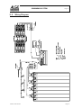
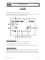
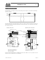
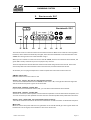
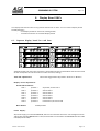
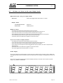
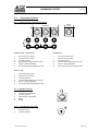
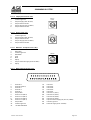
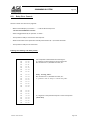
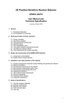
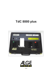
SWIMMING SYSTEM
Page 1
1 Eight-digit liquid crystal time-display in hours,
minutes, seconds and hundredths of seconds. While time is running, the hundredths
of seconds are not displayed.
10
DIN outlet mainly used to connect the
finish photocell of timer A (inputs for K0,
K1, and K2). Connection of power supply
(NLG4) is also possible.
2 Light emitting diode (LED) signals that the
Timer S4 is supplied with 9,5 Volt. If the
timer is driven by rechargeable batteries the
LED is lighted when batteries are loaded.
11
DIN outlet mainly used to connect the
finish photocell of timer B (inputs for K3,
K4, and K5). Connection of power supply
(NLG4) is also possible.
3 Meter for monitoring power supply, adjustment of photocell form parcoure A, B, C, and
conductive condition of the start-to-finishing
cable form parcoure A.
12
DIN outlet mainly used to connect the
finish photocell of timer C (inputs for K6,
K7, and K8). Connection of power supply
(NLG4) is also possible.
4 Knurled screws for loosening and fixing the
handle.
13
DIN outlet manly to connect the power
supply NLG4, identical with DIN outlet 10.
5 Toggle-switch to select clock A, B, or C.
Additional functions as indicated in the
instruction manual.
14
Connection for ALGE display board GAZc.
15
Connection for computer (serial RS 232c
interface).
16
Connection for Printer P4.
17
On/Off switch
18
Banana outlet (red and black) for
channel 9
19
Banana outlet (green and black) for channel 0
20
Banana outlet (green and black) for channel 3
21
Banana outlet (green and black) for channel 6
22
25-pin D-Sub-Miniature outlet with all 18
channels.
23
Indicates the internal setting:
red = rechargeable batteries
black = alkaline batteries
24
Outlet for countdown loud speaker (e.g. for
show jumping, swimming,...)
6 Start/Stop key with additional functions as
indicated in instruction manual.
7 Recall (next) button for stored times with
additional functions as indicated in instruction manual.
6+7 By simultaneously pushing keys 6+7 the
display as well as the pre-selected timer are
set at zero (only net times). As long as both
keys are pressed down, the display will show
only number eights to allow checking of all
the display´s segments.
8 Selector toggle-switch for choosing the
programs, testing the lines, and setting the
options adjustments.
Program selection: press toggle-switch
upwards and turn device with switch (17) on.
Line test: when pressing the toggle-switch
upwards it shows the condition of line on
meter (6).
Adjustment of options: when pressing
toggle-switch down it you can adjust the
options with the red and yellow key (6+7).
9 Connection for headset Q34.
Version : E-97-03-24
Page 1
SWIMMING SYSTEM
Page 2
TABLE OF CONTENTS
1. ALGE Swimming System ........................................................................................... 3
1.1. Timer S4 ........................................................................................................... 3
1.2. S4-SWIM .......................................................................................................... 3
1.3. Finish Adapter FIN1 ............................................................................................ 3
1.4. Touch Pad TP24 ................................................................................................ 3
1.5. Start Acoustic SA1 .............................................................................................. 4
1.6. Display Board GAZc ............................................................................................ 4
2. Installation of the Swimming System ............................................................................. 5
2.1. Description of Installation ..................................................................................... 5
2.2. Wiring Diagram .................................................................................................. 6
3. S4-SWIM ............................................................................................................... 7
4. Touch Pad TP24 ...................................................................................................... 9
5. Start Acoustic SA1 .................................................................................................. 11
6. Display Board GAZc ................................................................................................ 12
6.1. Separate display board for each lane .................................................................... 12
6.2. All times are shown on the same display board ....................................................... 13
7. Timer S4 for Swimming ............................................................................................ 14
7.1. Turn on of the Timer S4 ..................................................................................... 15
7.2. Adjustments for the S4 swimming program ............................................................ 16
7.2.1. Input the amount of impulses ...................................................................... 17
7.2.2. Input of the event number (WKNr.) .............................................................. 18
7.2.3. Input of the heat number (LFNr.) ................................................................. 18
7.2.4. Input of the delay time ............................................................................... 19
7.2.6. Printing the results ................................................................................... 19
7.2.7. Reset of the clock .................................................................................... 20
7.3 Memory .......................................................................................................... 21
8. Technical Data of the Timer S4 ................................................................................. 22
8.1. Connection System ........................................................................................... 23
8.1.1. Photocell Jacks and External Supply ............................................................ 23
8.1.2. Headset Jack (9) ..................................................................................... 23
8.1.3. Loud Speaker Jack (24) ............................................................................ 23
8.1.4 . Display Board Jack (15) ........................................................................... 24
8.1.5. Printer Jack (16) ...................................................................................... 24
8.1.6. RS 232c - Computer Jack (15) .................................................................... 24
8.1.7. Multi Channel Jack (22) ............................................................................. 24
8.2. Connection for the Display Board GAZc (14) .......................................................... 25
8.3. Computer Connection - RS 232c interface (15) ....................................................... 25
8.4. Connection for the Printer P4 (16) ........................................................................ 25
9. Starting Blocks with Relay Sensor .............................................................................. 26
9.1. False Start Control ............................................................................................ 27
9.2. Relay Error Control ........................................................................................... 28
Timer S4 manual copyright by:
Version: E-97-03-24
ALGE TIMING
AUSTRIA
Page 2
SWIMMING SYSTEM
Page 3
1. ALGE SWIMMING SYSTEM
1.1. TIMER S4:
The Timer S4 is a high precise timing device with sockets to plug other devices:
- Multi Channel Outlet to plug the S4-SWIM
- Socket to plug the Printer P4
- Socket to connect display boards GAZc
- RS 232c interface to connect a computer
- Socket to connect a headset (speech connection to the start)
The Timer S4 has built in rechargeable batteries and is able to supply the complete system for
about four hours. Normally is the Timer S4 connected to a 12 Volt car battery or with the net charging set NLG4.
1.2. S4-SWIM:
The S4-SWIM is connected with a 25 pin plug at the Timer S4. The S4-SWIM has eight outlets to
connect the cable to the Finish-Adapter (touch pad and handswitch). Built into the S4-SWIM are all
switches to turn the touch pads on or off, as well as the socket for the Start Acoustic SA1.
1.3. FINISH-ADAPTER FIN1:
One finish adapter is needed for two lanes. From the S4-SWIM to the Finish-Adapter is a 5-core
cable necessary. At each Finish Adapter you connect two touch pads and handswitch.
1.4. TOUCH PAD TP24:
It is a reliable mechanical system. Tape switches are inside the touch pad to make an impulse for
each touch of a swimmer. This construction makes an error free use possible. Waves or splashing
water will not effect the system and do not cause false impulses.
mechanical dimensions:2450 x 945 mm
active area: 2406 x 921
Version : E-97-03-24
Page 3
SWIMMING SYSTEM
Page 4
1.5. START ACOUSTIC SA1:
It consists of a central unit on which you can connect four horns, a headset and a handswitch. By
using the headset it is possible to talk with the operator of the timing device.
By pressing the handswitch the time of the S4 starts to run and the horns give the start signal. If you
press the handswitch within the next five seconds again it sends a false start signal.
1.6. DISPLAY BOARD GAZc:
You can connect up to eight display boards at the Timer S4 (one board for each lane). The display
board is controlled in order of finish arrival and shows rank, lane and time.
Version: E-97-03-24
Page 4
SWIMMING SYSTEM
2.
2.1.
Page 5
Installation of the ALGE Swimming System
Description of the installation:
For a complete swimming system you need the following devices:
1
1
1
1
4
8
8
1
4
2
1
Timer S4
Printer P4
Net Charging Set NLG4
S4-SWIM
Finish Adapter FIN1
Touch Pad TP24
Handswitch (manual times)
Start Acoustic SA1
Start Loudspeaker
Headset Q34
Start Handswitch
Cable Set
1 to 8 Display Board GAZc
Timer S4 - Printer P4:
Plug 5-pin plug from Printer P4 at Timer S4 (socket "printer")
Timer S4 - S4-SWIM:
Connect 25-pin plug at socket "multi channel" (22) at Timer S4
S4-SWIM - Start autistic SA1:
Connect S4-SWIM (socket "start") and Start Acoustic SA1 (socket "A" or "B") with cable 004.
S4-SWIM - Finish-Adapter FIN1:
Connect S4-SWIM and Finish-Adapter with cable 078. Cable 078 has after the cable number always
the cable length written. All four cables have a different length. You have to take care that the
shortest cable is connected with the closest FIN1, and so on. At the S4-SWIM you have to connect
the cable 078 that the numbers 1+2, 3+4, 5+6, 7+8 agree with the actual lanes.
Finish-Adapter FIN1:
Connect touch pad at finish adapter (red banana socket "TOUCH PAD").
Connect handswitch at finish adapter (blue banana socket "TOUCH PAD").
Attention: Connect on the left side only touch pads and handswitches of lane 1, 3, 5 and 7, and on
the right side only for lane 2, 4, 6 and 8.
Start acoustic SA1:
Connect a loudspeaker at the SA1 (socket "SPEAKER"). The second loudspeaker is connected on
the first, etc.
Connect the start handswitch on the green/black or red/black banana sockets.
Connect the headset on the socket with the headset symbol.
Version : E-97-03-24
Page 5
SWIMMING SYSTEM
Page 6
2.2. Wiring Diagram:
Version: E-97-03-24
Page 6
SWIMMING SYSTEM
Page 7
3. S4-SWIM
The S4-SWIM is necessary to switch the different touch pads on or off.
Connect the S4-SWIM with the 25-pin plug at the Timer S4 (socket "multi channel (22)"). If you turn
the S4 on, the red LED "supply" (34) of the S4-SWIM must shine.
Multi Touch Pad Switch (33):
Switch position "all on":all touch pads are active, the green LED shines
Switch position "all off":all touch pads are inactive, the red LED shines
Switch position "single":the touch pads can be switched on or off individual with switch 25 to 32.
Touch Pad Switch (25 to 32):
To turn the touch pads individual on or off. The Multi Touch Pad Switch (33) has to be on position
"single".
It is possible to make a manual stop impulse by pressing the Manual Stop Switch (36) on (up or
down) and the switch of the lane you need (25 to 32) towards the manual stop position (upwards).
Version : E-97-03-24
Page 7
SWIMMING SYSTEM
Page 8
Amphenol Connections:
1+2:
3+4:
5+6:
7+8:
Connection for cable to finish adapter of lane 1 and 2
Connection for cable to finish adapter of lane 3 and 4
Connection for cable to finish adapter of lane 5 and 6
Connection for cable to finish adapter of lane 7 and 8
All connections described above are made with cable 078. All cables 078 have a different length
(e.g. 078-38 = cable 078 with a length of 38 Meters). You should use the shortest cable for the
closest lane.
Start Socket (35):
Connect the Start Acoustic SA1 with the cable 004 from this plug
Manual Touch Pad Simulation (Switch 36 and 25 to 32):
You can make manual touch pad simulation with the S4-SWIM. If a touch pad does not make an
impulse for an intermediate time, simulate the impulse manually. This is necessary to have the
correct amount of touches at the end of the race. It is possible to make the manual stop impulse by
pressing the Manual Stop Switch (36) on (up or down) and the switch of the lane you need (25 to
32) towards the manual stop position (upwards).
Version: E-97-03-24
Page 8
SWIMMING SYSTEM
Page 9
4. Touch Pad TP24:
A touch pad is necessary for each lane. The whole yellow and black area is active as well as the
black rubber on the top, which protects the athletes from injuries.
The frame and the backside of the touch pad is made of stainless steel. The active area is a synthetic material which gives the pressure of a touch to the tape switch below it. A impulse is caused
by a pressure of about 3 kg.
The touch pad should be only in the water during the events. During the regular recreation swimming you must remove the touch pads. Use the ALGE touch pad cart to store them.
mechanical dimensions:
active area:
mounting:
weight:
2435 x 915 mm
2417 x 906 mm and active top
with fastening holder or customer made
about 30 kg
active area: 2417 x 906 mm
Side view of the touch pad:
active edge
touch pad frame is 10 mm thick,
the triggering point of the active
area is 9 mm
Version : E-97-03-24
Page 9
SWIMMING SYSTEM
Page 10
Mounting of the touch pad TP24:
Stanadard holder is the angle at the top of the touch pad. On request we can deliver the following
mounting solutions:
Detail
see
below
The touch pad holder of the touch pad has a M6 screw, which is fixed on both sides just above the
water level. You have to attach the touch pad to the pool wall that it is 30 cm above the water and
60 cm below the water.
Chrome steel pool:
Concrete pool or tile pool:
Sectional view A-A
touch pad TP24
holder
star-fastener
holder
Sectional view B-B
touch pad TP24
pool wall
star-fastener
dowel
holder
touch pad TP24
pool wall
touch pad TP24
holder
pool wall
You need an attachment to
fasten the touch pad. Ask
your pool supplier.
Dowel type: Hilti HIS-R M8
Bore-hole: Ø 12 mm
If your use the touch pad TP24 in a swimming pool with a lane width of 2.5 m it is possible to fix two
touch pad with one holder and one star-fastener.
Version: E-97-03-24
Page 10
SWIMMING SYSTEM
Page 11
5. Start acoustic SA1
Startakustik SA1
ext. supply
ready
on
off
37 38 39
start
40
41
42
43
44
TIMING
45
The start acoustic is a device used for events with mass start. Built into the SA1 are rechargeable
batteries, which will be automatically charged, when the start cable 004 is connected with the S4SWIM. Do not forget to turn the SA1 off after using it.
When you turn the SA1 on and connect it to the S4-SWIM, which is connected to the Timer S4, the
green LED "ready" blinks and you hear a peeps every second.
The first impulse form the handswitch starts the Timer S4 and gives the start sound. If there is a
second impulse from the handswitch within five seconds, it makes a false start sound.
At the SA1 you can plug a headphone in order to speak with the starter at the Timer S4.
ON/OFF switch (39):
Rotation switch to turn the unit on or off
Socket "ext. supply" (41 and 42, two identical sockets):
To connect the cable 004 with the S4-SWIM (socket "start" 35). Through this cable it charges the
SA1 and the start impulse is given to the Timer S4.
Socket with "Headset" symbol (43):
If you connect the headset at socket (43), you can talk to the headset at the Timer S4.
Socket with "speaker" symbol (40):
Socket to connect the start speaker. The second start speaker is connected at the first speaker, etc.
You can connect up to four speaker at a start acoustic. Set the speaker always between two lanes.
Socket "start" (44 and 45, two green/black banana sockets):
Two identical banana sockets to connect the handswitch to make the start- and false start impulse.
Meter (38):
Meter to control the power. When turning the SA1 on the needle should go into the green field. The
batteries are not charged, if the needle is in the red or white area.
Version : E-97-03-24
Page 11
SWIMMING SYSTEM
6.
Page 12
Display Board GAZc
The display board shows the running time as well as the run time. You can use the display board
the following way:
one display board for each lane (ranking board)
all times are shown on the same display board
6.1.
Separate display board for each lane:
A display board is for each lane necessary. The boards show the intermediate time and final time
of each competitor as well as the lane in order of arrival (ranking).
Timer S4 adjustments:
select with toggle switch (5) position "A-timer" or "B-timer"
Display board adjustments:
Thumb Wheel Switch:
rank 1
position 1
rank 2
position 2
rank 3
position 3
rank 4
position 4
rank 5
position 5
rank 6
position 6
rank 7
position 7
rank 8
position 8
Shift Switch:
top board, shows rank 1
shows rank 2
shows rank 3
shows rank 4
shows rank 5
shows rank 6
shows rank 7
lowest board, shows rank 8
middle position
Power Supply:
As power supply you need the NGAZ/R, which is connected to the mains. The voltage has to be
220 V (also available NGAZ/R for 110 V). Each board is connected to the NGAZ/R with the cable
033 (Amphenol cable).
Version: E-97-03-24
Page 12
SWIMMING SYSTEM
6.2.
Page 13
All times are shown on the same display board:
Adjustments when using one display board:
Timer S4:
select with toggle switch (5) position "C-timer"
Display board:
Thumb Wheel Switch:
Shift Switch:
position 0
middle position
Display all times:
- the display board shows automatically the winners time
- if you want to show the time of the 2nd place press the yellow button (7)
- if you want to show the next time press the yellow button (7) again
- when displaying the last time it starts to print the complete protocol on the printer
- if you press the yellow button again it shows the winner timer
- press the yellow and red button together to reset the clock
If
-
you do not want to display all times:
the display board shows automatically the winners time
if you want to show the time of the 2nd place press the yellow button (7)
if you want to show the next time press the yellow button (7) again
if you want to print the protocol move toggle switch (5) to position "A-timer" and press the
yellow button
- press the yellow and red button together to reset the clock
- move the toggle switch (5) to position "C-timer"
Power Supply:
If you use a display board with built in power pack you need no external power supply. With fully
recharged power pack it is possible to work all day without recharging. Charging time is about 14
hours.
If you have no built in powerpack inside the display board you need to use an external power
supply (e.g. NGAZc or NGAZ/R).
Version : E-97-03-24
Page 13
SWIMMING SYSTEM
Page 14
7. Timer S4
The Timer S4 is a very universal timing device. It includes software for many different sports.
Adjustment of the Printing Speed:
It is possible to adjust the printer speed for different printer types. The factory set up is "Pri 6.0".
This adjustment is perfect for the ALGE Printer P3. If you use the ALGE Printer P4 with this adjustment, it prints not on the full speed.
The best adjustment for the Printer P4 is "Pri 0.1". This adjustment guarantees a maximum printing
speed. If you use the Printer P3 with this adjustment, it will not print every line.
Best adjustment: Printer P4
Printer P3
Pri 6.0
Printer off
Pri 0.0
Pri 0.1
What you have to do to get to the point to have the possibility to adjust the Printing Speed is described in Point "Control-function". When the display (1) shows "Pri" and two numeric figures it is
possible to adjust the Printing Speed with the yellow and red button (6+7).
After you input the delay time you can input the printer speed:
- red button (6): number before the point increases
- yellow button (7):
number after the point increases
- correction:
press red button (6) until you pass the maximum printing time of 9.9. Now adjust
the printing speed with the red and yellow button.
Control-Function:
When display (1) shows "0:00.00" it is possible to see some important Timer S4 adjustments. The
last adjustment, which is shown is the Printing speed. It is now possible to change the printing
speed.
-
The display (1) shows "0:00.00"
-
Press toggle switch (8) to upper position (program+line test)
- The display (1) shows the program number and program version:
e.g.: Pr.6 V93.2
Program 6, Program Version 1993, second update
-
Occupied memory:
The display (1) shows the occupied memory
FULL 0.0
all memory is empty
FULL 0.5
memory is 50% empty
FULL 1.0
memory is full, clear memory!
-
Clear or keep memory when turning device on:
CLr JA
it clears memory when turning Timer S4 on
CLr nEIn
it keeps the memory when turning Timer S4 on
-
Baud rate of interfacd "display board" (14):
Adjustment must be 2400 baud
Bd1 2400 baud rate is 2400
Version: E-97-03-24
Page 14
SWIMMING SYSTEM
Page 15
-
Baud rate of interfacd "Printer" (16):
Adjustment must be 2400 baud
Bd2 2400 baud rate is 2400
-
Baud rate of interfacd "RS 232" (15):
Adjustment must be 2400 baud
Bd3 4800 baud rate is 4800
-
Measuring of the operation voltage:
e.g.:
BATT. 8.3 operation voltage (power supply or battery) is 8.3 Volt
-
The display shows the printing speed. Now you can change the printing speed with the red and
yellow button (6+7) or confirm it by pressing the red and yellow button (6+7) at the same time.
-
The display (1) shows again "0:00.00". Timer S4 is ready for timing.
7.1. Turn on of the Timer S4:
The S4 stores automatically the software, that was used. If you turn the S4 again on (switch 17), it
starts automatically with the same program.
If you use only the swimming program it loads automatically always the swimming program (as long
as you have no empty batteries).
If you want to change to another program you have to do the following:
- press the toggle switch (8) to the upper position (program+line test) and hold it
- switch the Timer S4 on (switch 17)
- display (1) shows the program number and version.
- press yellow button until you have the wanted program number on the display
- press red and yellow button (6+7) start the program
The different programs of the Timer S4:
Program
Program Number
SPLIT or SEQUENTIAL
Pr. 0
3-Course-Timer
Pr. 1
SHOW JUMPING
Pr. 2
18-CHANNEL-TIMER
Pr. 3
PARALLELSLALOM (Pro Format)
Pr. 4
SPEED
Pr. 5
SWIMMING
Pr. 6
AUTOMATIC
Pr. 7
Version : E-97-03-24
Page 15
SWIMMING SYSTEM
Page 16
7.2. Adjustments for the S4 swimming program:
Before you start an event you have to input some important data for the race:
-
Set toggle switch (5) on position "A-timer" or "B-timer" (to select the swim timer).
-
Turn the Timer S4 on and choose the "swimming program" (Prog. 6).
-
Wait until the display (1) shows "A00" and the Printer P4 prints "EINGABE ANSCHLAEGE".
-
Toggle switch (5) on position "A-timer" or "B-timer" when using a display board for each lane, on
position "C-timer" when using one board for all lanes.
-
Input the amount of impulses of the touch pad (1 to 99 impulses are possible). With red key (6)
input tens, with yellow key (8) input ones.
e.g.: 1500 Meter means the a swimmer touches the touch pad 15 times
Press once the red key (6) and five times the yellow key (8). The display shows now 15. If
you input too many touches, press the red key until the number get higher than 99. Now it
starts form one again.
-
Press red and yellow button (6+7) together to store the amount of impulses.
-
The display (1) shows "En01" and the printer prints "EINGABE WKNr".
-
Input event number:
Input the event number like the amount of touches. With the red key (6) input tens, with the
yellow key (8) input ones. It is possible to adjust the event between 1 and 99.
-
Press red and yellow button (6+7) together to store the event number.
-
The display (1) shows "Hn01" and the printer prints "EINGABE LFNr".
-
Input heat number:
Input the heat number like the amount of touches. With the red key (6) input tens, with the yellow
key (8) input ones. It is possible to adjust the heat between 1 and 99.
-
Press red and yellow button (6+7) together to store the heat number.
-
The display (1) shows "d10" and the printer prints "EINGABE TOTZEIT".
-
Input delay time:
The delay time is the time after an impulse during which the touch pad is inactive. Input the delay
time like the amount of touches. With the red key (6) input tens, with the yellow key (8) input
ones. It is possible to adjust the delay time between 10 and 99 seconds.
-
The display (1) shows "0:00.00" and is ready for the start.
-
The Timer S4 is ready for timing.
-
If you receive a start impulse it starts the clock. You can see the running clock on display (1).
-
The Printer P4 prints every stop impulse from the touch pad at once.
Version: E-97-03-24
Page 16
SWIMMING SYSTEM
Page 17
-
As soon as all swimmer reached the maximum amount of touches, it prints the a ranking of the
run times, the manual times, and the finish times sorted by lanes.
-
If not all swimmer reach the finish, it is possible to make the final printouts by pressing the red
key (6).
-
If all swimmer finished the competition, and the Printer finished printing, you can reset the time
for the next race by pressing the red (6) and yellow (8) button at the same time.
-
If you want to change the amount of impulses, event or race number, or the delay time press the
red and yellow button (6+7) again.
-
The timer is ready for the next start.
7.2.1. Input the amount of impulses:
Input the amount of impulses at the touch pad (swimming distance) before the start. It is very
important to input the correct amount, because a wrong number could cause that the intermediate
times is valued like the finish time and the finish times will not be stopped.
e.g.
50 m swimming pool, touch pads on one side of the pool, event distance is 200 m:
Since the touch pad is only on one side, it has for 100 m only one impulse, which means you
need to input 2 impulses.
e.g.
50 m swimming pool, touch pads on both sides of the pool, event distance is 200 m:
Since the touch pad is on both sides, it has every 50 m an impulse, which means you need to
input 4 impulses.
e.g.
25 m swimming pool, touch pads on one side of the pool, event distance is 200 m:
Since the touch pad is only on one side, it has for 100 m two impulse, which means you need
to input 4 impulses for 200 m.
When turning the Timer S4 Swimming program on you have always to input the amount of impulses, event number, heat number and delay time. This adjustments you can make also after
resetting the timing device to "0:00.00" by pressing the red and yellow button (6+7) at the same
time.
-
red button (6):
yellow button (7):
minimum amount of touches:
maximum amount of touches:
correction:
-
change after a race:
Version : E-97-03-24
each input means 10 impulses
each input means 1 impulse
1
99
press red button (6) until the amount of touches is over 99.
Now it starts to count from the beginning.
after the race you reset the timer by pressing the red (6) and
yellow (8) button at the same time. If you press both buttons
again you can input the amount of touches, event, heat,
delay time, and printing speed.
Page 17
SWIMMING SYSTEM
Page 18
Amount of touches for different distances for a 50 m swimming pool (touch pad is only on the finish side)
Schwiming distance
Amount of impulses
50 m
1
100 m
1
200 m
2
400 m
4
800 m
8
1000 m
10
1500 m
15
4 x 50 m
2
4 x 100 m
4
4 x 200 m
8
7.2.2. Input of the event number (WKNr.):
After you input the amount of touches you have to input the event number. The display (1) shows "En01"
-
red button (6):
yellow button (8):
minimum event number:
maximum event number:
each input means a increase of 10 events
each input means a increase of 1 event
1
99
-
correction:
press red button (6) until the event number is over 99. Now it
starts to count from the beginning.
-
change after a race:
after the race you reset the timer by pressing the red (6) and
yellow (8) button at the same time. If you press both buttons
again you can input the amount of touches, event, heat,
delay time, and printing speed.
7.2.3. Input of the heat number (LFNr.):
After you input the amount of touches and event number you have to input the heat number. The
heat number increases automatically when you reset the timer after the end of a race. The display
(1) shows "Hn01".
-
red button (6):
yellow button (8):
minimum heat number:
maximum heat number:
Version: E-97-03-24
each input means a increase of 10 heats
each input means a increase of 1 heat
1
99
Page 18
SWIMMING SYSTEM
Page 19
-
correction:
press red button (6) until the heat number is over 99. Now it
starts to count from the beginning.
-
change after a race:
after the race you reset the timer by pressing the red (6) and
yellow (8) button at the same time. If you continue now with
the next start it increases the heat number automatically to
the next higher number. If you press both buttons again you
can input the amount of touches, event, heat, delay time, and
printing speed.
7.2.4. Input of the delay time:
The delay time is the time after an impulse, during which the touch pad is inactive. Input the delay
time like the amount of touches. It is possible to adjust the delay time between 10 and 99 seconds.
You have to adjust a long delay time for a rally, because a swimmer that reaches the finish could
cause additional impulses before he leaves the water.
The touch pad is locked after each touch for the duration of the delay time (it cannot cause another
impulse).
After you input the amount of touches, event, and heat you have to input the delay time.
-
red button (6):
yellow button (8):
minimum delay time:
maximum delay time:
each input means a increase of the delay time of 10 seconds
each input means a increase of the delay time of 1 second
10
99
-
correction:
press red button (6) until the delay time is over 99. Now it
starts to count
from the beginning.
-
change after a race:
after the race you reset the timer by pressing the red (6) and
yellow (8) button at the same time. If you press both buttons
again you can input the amount of touches, event, heat,
delay time, and printing speed.
7.2.5. Printing the run times:
As soon as all swimmer reach the maximum amount of touches, it prints the ranking of the run
times, the manual times, and the finish times sorted by lanes.
If not all swimmer reach the finish or a lane is empty, it is possible to make the final printout by
pressing the red button (6).
It prints the following:
all intermediate times
all finish times in order of arrival
ranking list
list with all manual times
lane list to write the times into the protocol
Version : E-97-03-24
Page 19
SWIMMING SYSTEM
02 ANSCHLAEGE
TOTZEIT 10 Sek.
WKNr. 02 LFNr. 05
0:00.00
A 01
A 01
A 01
A 01
A 01
A 01
A 01
A 01
A 02
A 02
A 02
A 02
A 02
A 02
A 02
A 02
1.
2.
3.
4.
5.
6.
7.
8.
M
M
M
M
M
M
M
M
8.
6.
3.
1.
2.
4.
5.
7.
B4
B5
B3
B6
B2
B7
B8
B1
B4
B5
B3
B6
B7
B2
B8
B1
0:55.39
0:55.59
0:56.17
0:56.52
0:57.06
0:57.45
0:57.52
0:57.62
1:49.31
1:49.35
1:50.52
1:50.70
1:51.40
1:51.85
1:52.28
1:52.66
B4
B5
B3
B6
B7
B2
B8
B1
1:49.31
1:49.35
1:50.52
1:50.70
1:51.40
1:51.85
1:52.28
1:52.66
B4
B5
B3
B6
B7
B2
B8
B1
1:49.36
1:49.40
1:50.59
1:50.74
1:51.39
1:51.88
1:52.29
1:52.69
B1
B2
B3
B4
B5
B6
B7
B8
1:52.66
1:51.85
1:50.52
1:49.31
1:49.35
1:50.70
1:51.40
1:52.28
7.2.6.
Page 20
amount of impulses is two
delay time is 10 seconds
event number is 2, heat number is 5
timer is ready for the start
A 01 = first impulse, B 4 = lane 4, intermediate time is 55.35 sec.
A 01 = first impulse, B 5 = lane 5, intermediate time is 55.59 sec.
A 01 = first impulse, B 3 = lane 3, intermediate time is 56.17 sec.
A 01 = first impulse, B 6 = lane 4, intermediate time is 56.52 sec.
A 01 = first impulse, B 2 = lane 2, intermediate time is 57.06 sec.
A 01 = first impulse, B 7 = lane 7, intermediate time is 57.45 sec.
A 01 = first impulse, B 8 = lane 8, intermediate time is 57.52 sec.
A 01 = first impulse, B 1 = lane 1, intermediate time is 57.62 sec.
A 02 = second impulse, B 4 = lane 4, time is 1 min. 49.31 sec.
A 02 = second impulse, B 5 = lane 5, time is 1 min. 49.35 sec.
A 02 = second impulse, B 3 = lane 3, time is 1 min. 50.52 sec.
A 02 = second impulse, B 6 = lane 6, time is 1 min. 50.70 sec.
A 02 = second impulse, B 7 = lane 7, time is 1 min. 51.40 sec.
A 02 = second impulse, B 2 = lane 2, time is 1 min. 51.85 sec.
A 02 = second impulse, B 8 = lane 8, time is 1 min. 52.28 sec.
A 02 = second impulse, B 1 = lane 1, time is 1 min. 52.66 sec.
Ranking List:
1st rank, lane 4, final time 1minute 49.31 seconds
2nd rank, lane 5, final time 1minute 49.31 seconds
3rd rank, lane 3, final time 1minute 49.31 seconds
4th rank, lane 6, final time 1minute 49.31 seconds
5th rank, lane 7, final time 1minute 49.31 seconds
6th rank, lane 2, final time 1minute 49.31 seconds
7th rank, lane 8, final time 1minute 49.31 seconds
8th rank, lane 1, final time 1minute 49.31 seconds
Manual timing:
manual time, lane 4, time 1 minute 49.36 seconds
manual time, lane 5, time 1 minute 49.40 seconds
manual time, lane 3, time 1 minute 50.59 seconds
manual time, lane 6, time 1 minute 50.74 seconds
manual time, lane 7, time 1 minute 51.39 seconds
manual time, lane 2, time 1 minute 51.88 seconds
manual time, lane 8, time 1 minute 52.29 seconds
manual time, lane 1, time 1 minute 52.69 seconds
Times listed by lanes:
rank 8, lane 1, final time is 1 minute 52.66 seconds
rank 6, lane 2, final time is 1 minute 51.85 seconds
rank 3, lane 3, final time is 1 minute 50.52 seconds
rank 1, lane 4, final time is 1 minute 49.31 seconds
rank 2, lane 5, final time is 1 minute 49.35 seconds
rank 4, lane 6, final time is 1 minute 50.70 seconds
rank 5, lane 7, final time is 1 minute 51.40 seconds
rank 8, lane 8, final time is 1 minute 52.28 seconds
Reset of the clock:
Press red and yellow button (6+7) at the same time.
Version: E-97-03-24
Page 20
SWIMMING SYSTEM
Page 21
7.3. Memory:
This feature is designed to allow users of the S4 with a computer interface to access times stored in
memory. You must use a computer to take advantage of this feature. The default setup from the
factory has the S4 automatically recording all times up to 8000. When turning the device on it shows
you on the display how much memory is occupied:
FULL: 0.0 ........... memory is empty, free memory capacity is about 8000 times
FULL: 0.5 ........... memory is 50% full, free memory capacity is about 4000 times
FULL: 1.0 ........... memory is full, you need to clear the memory
The memory can store up to 8000 times with a continuous ID number assigned to each time (see
data format of each program). During operation you can check the free memory space with the
control function by pressing the toggle switch (8) upwards. If you plan to download data from the
memory clear the S4 prior to the competition.
Clear Memory:
There are two ways to clear the memory:
o from the RS 232 interface:
A hexadecimal code is transferred from a computer through the RS 232 interface.
o when turning the S4 on:
- press toggle switch (8) to upper position
- turn device on (switch 17)
- release toggle switch (8)
- select program with the yellow key (7)
- press toggle switch (8) to upper position
- display (1) shows "CLr nEIn" (= clears memory not)
- press yellow button (7)
- display (1) shows "CLr JA" (= clears memory)
- press red and yellow button (6+7) at together
- memory will be cleared each time you turn the device on, as long as you do not switch
back to "CLr nEIn".
During the timing mode you can check the adjustment for the memory by pressing the toggle
switch (8) to the upper position.
Transmission of the memory:
You can transmit the memory at any time during the operation of the Timer S4. The transmit order
must be given by the computer through the RS 232 interface. The Timer S4 starts to transmit as
soon as it receives the hexadecimal code 85.
Memory output in blocks:
It is possible to output a block of data from the memory (RAM) of the Timer S4 using the RS 232 interface
(15). You have to input the hexadecimal code 84, the first address and the last address in ASCII.
e.g.: 84(Hex)09341330 = output of all data from memory number 934 to 1330 through the RS 232
interface
Version : E-97-03-24
Page 21
SWIMMING SYSTEM
Page 22
8. TECHNICAL DATA of the Timer S4:
Measuring range:
23 hours, 59 minutes, 59.999 seconds
Crystal frequency:
TCXO 9.216 MHz (Temperature compensated Crystal Oscillator)
Accuracy:
at changeable temperature:
Aging:
Frequency adjustment:
+/- 2,5 ppm at -30 to +75°C (+/-0,009 sec/h)
+/- 1 ppm per year
+/- 0,1 ppm at +25°C
Operative timing range:
-25 to 50°C
Memory:
8000 times with continuous ID number;
memory is unaffected when device is turned off due to built in
batteries.
Display:
Liquid Crystal Display, 8 digits, figure height 12,7 mm
Electronic:
the most advanced CMOS technology
Power consumption:
without external devices, from internal battery: about 60 mA per hour
without external devices.
Operating elements:
1
1
1
1
1
Casing:
anodized aluminium case
L x W x H = 226 x 162 x 95
Weight:
2.2 kg (with batteries)
Version: E-97-03-24
on/off switch
(17)
red button "start/stop" (6)
yellow button "next"
(7)
toggle switch "A-, B- and, C-timer"
(5)
toggle switch "program+line test, delay time" (8)
Page 22
SWIMMING SYSTEM
8.1.
Connection System:
8.1.1
Photocell jacks and external supply:
Page 23
extern
supply
photocell
5
1 5
6
4
1 5
2 4
2 4
3
c9
3
1
5
2
4
2
3
A
B
C
c0
c3
c6
3
A´
Jack A and A´ (10 and 13):
Jack B (11):
1
2
3
4
5
6
1
2
3
4
5
6
input channel 0 (start)
input channel 1 (stop)
common ground
input external supply (6 to 15 Volt)
output +5 Volt stabilized
input channel 2 (intermediate time)
1
input channel 3 (start)
input channel 4 (stop)
common ground
input external supply (6 to 15 Volt)
output +5 Volt stabilized
input channel 5 (intermediate time)
Jack C (12):
1
2
3
4
5
6
input channel 6 (start)
input channel 7 (stop)
common ground
input external supply (6 to 15 Volt)
output +5 Volt stabilized
input channel 8 (intermediate time)
8.1.2. Headset Jack (9):
1
2
3
4
5
microphone of headset
common ground
loud speaker of headset
empty
empty
3
5
1
4
2
8.1.3. Loud Speaker Jack (24):
1
2
speaker signal
common ground
Version : E-97-03-24
1
2
Page 23
SWIMMING SYSTEM
Page 24
8.1.4. Display Board Jack (14):
1
2
3
4
5
displayboard
common ground
output supply (6 to 15 Volt)
output data channel 1
output supply (6 to 15 VDC)
output data channel 2
5
2
4
1
3
8.1.5. Printer Jack (16):
1
2
3
4
5
printer
common ground
output supply (6 to 15 Volt)
output data channel 1
output supply (6 to 15 VDC)
output data channel 2
5
2
4
1
3
8.1.6. RS 232c - Computer Jack (15)):
1
2
3
4
5
6
7
8
data TXD
common ground
data RXD
CTS
RTS
empty
output external supply (6 to 15 VDC)
empty
RS232
8
3
5
6
2
7
1
4
8.1.7. Multi Channel Socket (22):
14 15 16 17 18 19 20 21 22 23 24 25
1
1
2
3
4
5
6
7
8
9
10
11
12
13
channel 9
channel 0 (start)
channel 2
channel 3
channel 7
output data
channel 10 (I/O 0)
channel 12 (I/O 2)
channel 15 (I/O 5)
channel 17 (I/O 7)
output data
common ground
+5 VDC stabilized
Version: E-97-03-24
2 3
4
5 6
7 8
9 10 11 12 13
14
15
16
17
18
19
20
21
22
23
24
25
channel 1
channel 5
channel 8
channel 6
channel 4
channel 11 (I/O 1)
channel 13 (I/O 3)
channel 16 (I/O 6)
channel 14 (I/O 4)
output external supply (5,3 to 14,3 VDC)
common ground
external supply (6 to 15 VDC)
Page 24
SWIMMING SYSTEM
8.2.
Page 25
Connection for the display board:
Transfer format: 1 start bit, 8 ASCII bit, no parity bit, 1 stop bit
Transfer speed:
2400 baud
Pin connection:
see page 24
Data format for swimming:
Ixxx.xxxxxxxMM:SS.z(CR)
running time
IxxxxxxxxxBxMM:SS.zh(CR)
stopped time
I ................... address for display board A to K
x .................. blank
MM:SS.z ....... time in minutes, seconds, and 1/10 seconds
B .................. lane (1 to 8)
MM:SS.zh ...... time in minutes, seconds, and 1/100 seconds
(CR) ............. carriage return
Data cable from Timer S4 to display board GAZc:
o cable 010-10
o extension with cable reel KT 300 or KT 500
If you use the power supply NGAZ/R for the ranking board, then you have to plug cable 010 or the
cable reel on the banana sockets of the NGAZ/R.
8.3. RS 232c Interface (15):
Transfer format: 1 start bit, 8 ASCII bit, no parity bit, 1 stop bit
Transfer speed:
4800 baud
Pin connection:
see page 24
Data format for swimming:
####xxBBxHH:MM:SS.zht(CR)
touch pad time
####xMBBxHH:MM:SS.zht(CR)
manual time
# .................. continuous ID number (4 digits)
x .................. blank
BB ................ shows the lane, e.g. B3 = lane 3
HH:MM:SS.zht time in hours, minutes, seconds, and 1/1000 seconds
MBB ............. M for manual time, BB shows the lane
HH:MM:SS.zht time in hours, minutes, seconds, and 1/1000 seconds
(CR) ............. carriage return
Cable:
8.4.
066-03 ...... Timer S4 - Computer with 25 pin plug
067-02 ...... Timer S4 - Computer with 9 pin plug
Connection for Printer P4 (16):
Plug the cable of the Printer P4 at the Timer S4 (plug printer (16).
Transfer format:
Transfer speed:
Pin connection:
Data fromat:
Version : E-97-03-24
1 start bit, 8 ASCII bit, no parity bit, 1 stop bit
2400 baud
see page 24
see page 20
Page 25
SWIMMING SYSTEM
9.
Page 26
Starting Blocks with Relay Sensor
For the Relay Sensor (built into the starting blocks) you need a separate Timer S4 and P4. You
select the program as for swimming, but the toggle switch (5) must be on position "C-timer".
For the "False Start Control" and "Relay Start Control" you need the following components:
-
Starting Blocks with Relay Sensor
Timer S4 (additional Timer S4)
Printer P4 (additional Printer P4)
Adjustments for the Timer S4:
-
Set toggle switch (5) on position "C-timer" (to select the relay timer).
-
Turn the Timer S4 on and choose the "swimming program" (Prog. 6).
-
Wait until the display (1) shows "- - - -" and the Printer P4 prints
"FEHLSTARTUEBERWACHUNG".
-
Toggle switch (5) on position "A-timer" or "B-timer" when you want to control only the start, on
position "C-timer" when you want to control the start and relay.
Version: E-97-03-24
Page 26
SWIMMING SYSTEM
Page 27
9.1. False Start Control:
Start the Timer as it shows on the page before.
-
Wait until the display (1) shows "- - - -" and the Printer P4 prints
"FEHLSTARTUEBERWACHUNG".
-
Set the toggle switch (5) on position "A-timer" or "B-timer".
-
The system is ready to receive the first impulse.
-
Five seconds after the start the system resets automatially.
-
The system is ready for the next start.
Printing the Starting Times:
No false start:
+0.04
+0.08
+0.10
+0.11
+0.11
+0.13
+0.14
+0.20
All competitors started after the start signal.
A "positive" time is always a correct start time.
B1 means Lane 1, B2 means Lane 2, etc.
B3
-0.05
A negative time is always a false start.
B5
B4
B1
B7
B2
B6
B8
+0.04
+0.08
+0.11
+0.11
+0.13
+0.14
+0.20
B3
B5
B4
B1
B7
B2
B6
B8
With false start:
Version : E-97-03-24
Page 27
SWIMMING SYSTEM
9.2.
Page 28
Relay Error Control:
Start the Timer as it shows on page 26.
-
Wait until the display (1) shows "- - - -" and the Printer P4 prints
"FEHLSTARTUEBERWACHUNG".
-
Set the toggle switch (5) on position "C-timer".
-
The system is ready to receive the first impulse.
-
After the end of the race press the red and yellow button (6+7) to reset the timer.
-
The system is ready for the next start.
Printing the Starting and Relay Times:
B3
B5
B4
B1
B7
B2
B6
B8
+0.04
+0.08
+0.10
+0.11
+0.11
+0.13
+0.14
+0.20
All competitors started after the start signal.
A "positive" time is always a correct start time.
B1 means Lane 1, B2 means Lane2, etc.
B4
B6
B5
B3
B1
B7
B2
B8
+0.03
+0.04
+0.05
+0.03
+0.07
+0.05
+0.04
+0.06
Relay starting times:
B1 means Lane 1, B2 means Lane2, etc.
A "positive" time is always a correct relay time.
B4
B5
B3
B6
B1
B2
B7
B8
+0.06
+0.05
+0.05
-0.04
+0.09
+0.03
+0.02
+0.05
Version: E-97-03-24
A "negative" relay time is always a incorrect relay start
(false start)
Page 28
SWIMMING SYSTEM
Page 29
Installation of the swimming system with relay sensor:
Version : E-97-03-24
Page 29