1
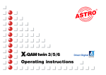
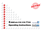
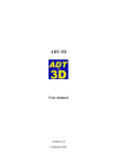
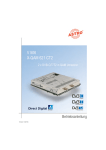
Slot 1
Slot 2
Slot 3
Slot 4
Slot 5
Slot 6
Slot 7
Slot 8
Power A
Power B
16
SAT-HEADEND
Figures
V16 Base Unit without Cards
Bus adapter
LED indicator lamps
Interlocking device
2 temperature
regulated fans
SAT distribution
board
Slots
Redundant power supply
The V16 is CE certified and complies with all relevant EN standards.
Changes and printing errors reserved. Version: March 2004.
2
Contents
Must be observed: Hazard and safety information . . . . . .
Figure of V16
1 Safety information
3
1
Pictographs and safety information
..............................
2
Pictographs are icons with specific meanings. The follo-
1
Pictographs . . . . . . . . . . . . . . . . . . . . . . . . . . . . . . . . .
3
wing pictographs are used in the installation and opera-
2
Hazard and safety information
..................
3
ting instructions:
2.1
Installation instructions . . . . . . . . . . . . . . . . . . . . . . . .
3
Warns about situations in which there is danger of lethal
2.2
Opening the housing
.........................
4
injury due to hazardous electrical voltage and non-com-
2.3
Potential equalization and grounding . . . . . . . . . . . . . .
5
pliance with these instructions.
3
Preparing the base unit . . . . . . . . . . . . . . . . . . . . . . . .
5
Warns about various hazards to health, environment and
3.1
Mounting bracket . . . . . . . . . . . . . . . . . . . . . . . . . . . . .
5
materials.
3.2
Installation and deinstallation of SAT distribution board VMS 616
5
3.3
Power supply unit changeover (VSN 1 <> VSN 2) . . . .
5
3.4
LNB remote supply (for VMS 616) . . . . . . . . . . . . . . . .
6
3.5
Remote supply voltage on HF output . . . . . . . . . . . . . .
7
4
Configuration of V16 and VMS 616 . . . . . . . . . . . . . . .
7
4.1
Setting VMS 616 mode
.......................
7
Electrical scrap must not be placed in household refuse;
4.2
Setting bus address . . . . . . . . . . . . . . . . . . . . . . . . . .
8
it must be disposed of by means of a special waste recy-
4.3
Temperature . . . . . . . . . . . . . . . . . . . . . . . . . . . . . . . .
8
cling company. If you have any questions about waste
5
Installing plug-in cards . . . . . . . . . . . . . . . . . . . . . . . .
8
disposal, your local environmental agency would be glad
5.1
Cards with SAT tuner (SAT VMS 616 distribution board) . . . .
8
to give you further information about recycling.
☞
This is a general information symbol.
Recycling: All of our packaging materials (packaging,
identification sheet, plastic foil and bag) are fully recyclable.
5.2
Cards with SAT tuner (SAT distribution board VSF 8) . .
9
5.3
Cards for terrestrial conversion . . . . . . . . . . . . . . . . . .
9
5.4
(De-) Modulator cards
........................
9
5.5
Uninstalling plug-in cards . . . . . . . . . . . . . . . . . . . . . . .
10
6
Configuration of all plug-in cards . . . . . . . . . . . . . . . . .
10
The device may be installed only in dry rooms and on
7
Indicators (front LEDs) . . . . . . . . . . . . . . . . . . . . . . . . .
10
vertical surfaces.
8
Level adjustment . . . . . . . . . . . . . . . . . . . . . . . . . . . . .
11
Installation location: indoors
Technical specifications . . . . . . . . . . . . . . . . . . . . . . . .
12
The device can be fastened to the wall using the supplied
Accessories . . . . . . . . . . . . . . . . . . . . . . . . . . . . . . . . .
12
mounting materials.
9
3
2
Hazard and safety information
2.1
Installation instructions
2 Hazard and safety information
2 Hazard and safety information
The device must not come into contact with splashing or
dripping water. Containers with liquid must not be placed on
the device.
If there is condensation, wait until the device is completely
dry. The device generates heat which must be able to escape. It is therefore important that the vents are never covered. The accumulation of heat negatively influences the service life of the device and is a source of danger.
The specified minimum distances (at least 30 cm above and
below) must be strictly observed. This applies above all
when several devices are installed one over the other. By
means of appropriate measures (e.g. the use of a specially
designed air flow unit), the minimum distance between devices can be reduced if required.
The permitted ambient temperature is 0...50°C. Installation
in unventilated cabinets or alcoves is not permitted.
Installation is permitted only in rooms which maintain the
permitted ambient temperature even in changing climatic
conditions.
Warning: When the device is installed in places such as
storage areas and roof trusses, it must be ensured that the
permitted ambient temperature is maintained.
If auxiliary fans are used for convection, it must be ensured
that in the event of fan failure the device is disconnected
from the power supply by means of appropriated measures
in order to prevent damage to the device.
Because of fire hazard due to lightening, it is recommended
that all mechanical parts (e.g. V16, equipotential busbars,
distributors, etc.) are mounted on non-combustible underlays. Combustible materials include wooden beams, wooden boards, plastics, etc.
2.2
Opening the housing
Before opening the housing:
Be sure to disconnect the power plug.
(Be careful when doing maintenance work on the power
supply unit. There is also danger of injury after disconnecting the power supply due to electrically live elements.)
Do not service during thunder storms.
Opening the device must be done only by authorized personnel according to the national regulations, or by sending
the device to ASTRO with an exact description of the fault.
Replace the power cables only with an original part power
cable.
Replace fuses only with those of the same type, value and
melt characteristics.
Important:
DIN VDE 0701 Part 1 and 200, servicing; EN 50 083 Part
1, safety requirements
4
3 Preparing the base unit
2.3
3 Preparing the base unit
Potential equalization and grounding
To do this, place bracket slots over the fittings on the
base unit, push to the stop and fasten securely with the
middle screw.
The proper grounding and installation of the system must comply with EN 50 083 Part 1.
The VSN 1 and VSN 2 power supplies may be operated only in
devices for which these power supplies have been approved
and, due to high discharge current, only in power supply networks
with a protected (grounded) circuit system (TN systems in compliance with EN 60950).
Regulations in compliance with EN 50083 Part 1 and national regulations concerning IT/TT power supply networks must be observed.
3.2
If a SAT VMS 616 distribution board is to be subsequently
installed to a V16 base or an already installed VMS 616 is to
be removed, the change must be set in the software of the
base device. This can be done either by using the ASTRO
HE programming software or the KC 3 manual device. For
this, after installing or removing the VMS 616, close the housing, apply mains voltage, and connect the KC 3.
Operation without equipment grounding conduction, device
grounding or device potential equalization is not permitted
3
Preparing the base unit
3.1
Mounting bracket
Installation and deinstallation of SAT VMS 616
distribution board
ASTRO V16
Version X.XX
1= deutsch
(next<>)
Fasten the supplied mounting bracket either on the front panel
(19" installation, Fig. 1) or rear panel (wall mounting, Fig. 2).
V16 Setup
VMS 616
Yes
Power
A+B
Password Off
The following display appears:
After pressing the "Menu" key the setup display
appears.
Select line 2 with the ↑ or ↓ arrow key. Use the ← or →
arrow key to set VMS 616 installation status.
☞
An incorrect setting of the VMS 616 installation status leads to faulty functions in the choice of band /
polarization of the installed plug-in cards!
3.3
Power supply changeover (VSN 1 <> VSN 2)
Warning:
Fig. 1
Fig. 2
Installation work on the power supply unit may be performed only if the power plug(s) is disconnected.
5
3 Preparing the base unit
3 Preparing the base unit
The power supply unit (power
If in a V16 base a single power unit (VSN 1) is to be subsequently exchanged for a redundant one (VSN 2) or vice
versa, the change must also be set in the software of the
base device. This is done using the KC 3 manual device.
After exchanging the power unit, close the housing, apply
mains voltage, and connect the KC 3.
supply carrier) is secured with
outside screws and screws at
two points inside. These have to
be loosened for deinstallation.
ASTRO V16
Version X.XX
1= deutsch
(next<>)
(Fig. 3 & 4)
When uninstalling, it’s best first
to remove the plug-in cards at
Fig. 3
V16 Setup
VMS 616
Yes
Power
A+B
Password Off
slot 1 and slot 8 using the plug-in
card removal tool.
To press out the power supply unit
carriers, the plug-in card removal
tool is alternately placed on the nuts
on the side and pressed. This relea-
The following display appears:
After pressing the "Menu" key the setup display
appears.
Select line 3 with the ↑ or ↓ arrow key.
Use the ← or → arrow key to set the installation status
to VSN 1 (Power A) or VSN 2 (Power A+B).
☞
An incorrect setting of the VSN … installation status
leads to faulty signaling (front LEDs) and incorrect
function displays of the HE programming software.
3.4
LNB remote supply (for VMS 616)
ses the plug contacts of the power
supply carrier from the base.
Fig. 4
When using the internal SAT VMS 616 distributor field, the LNB
remote power supply
can be switched on for
up to four of the six
SAT inputs (each max.
250 mA, short-circuit
proof). On the mainboard there are four jumpers between card slot
four and five with which
(see Fig. 5).
(See also Chapter 5.5.
Installing
plug-in cards.)
Fig. 5
Fig. 6
6
3 Preparing the base unit
4 Configuration of V16 and VMS 616
the remote power supply can be activated for each
of the inputs. Activated remote power supplies are
indicated by adjacent LEDs (Fig. 6).
4
Apply mains voltage and connect KC 3.
The following display appears:
SAT inputs for which LNB remote power supply can
be activated: inputs 11, 13, 15 and 16.
3.5
Configuration of V16 and VMS 616
3.5 Remote supply voltage on HF output
If an ASTRO network (U901 or VZN9) is employed
for the active signal consolidation of multiple V16s,
the power supply required for this device can be
provided by a V16 base unit. Located on the mainboard at slot one is a jumper with which the remote supply voltage can be activated for the HF output. The activated remote supply voltage is indicated by an adjacent LED (Fig. 7).
ASTRO V16
Version X.XX
1= deutsch
(next<>)
Line 2 displays the software status of the mainboard
processor. Pressing "1" selects German.
V16 Parameter
VMS -Inputs 11-14
Bus adress XXX
TemperatureXX°C
Select the next menu with the arrow key. The V16
parameters are displayed.
4.1
Setting VMS 616 mode
The internal SAT VMS 616 distribution board has two
operating modes:
Standard mode:
Inputs 11-14 can be switched via software to all 16 outputs (card 1 tuner A to card 8 tuner B).
This mode is always recommended if not more than four
different polarization levels for all installed conversion
cards are required.
Expanded mode:
Inputs 11, 12, 15 and 16 can be switched via software
to the first four outputs (card 1 tuner A to card 2 tuner
B). Inputs 11-14 can be switched via software to the last
12 outputs (card 3 tuner A to card 8 tuner B).
geschaltet werden.
Fig. 7
7
4 Configuration of V16 and VMS 616
5 Installing plug-in cards (VSF 8)
This mode is to be activated if more than four different
polarization levels for all installed conversion cards are
required.
5
Installing plug-in cards
Lift out and remove the interlocking device by lightly
pressing to the right (Fig. 8).
For this operating mode, of course the plug-in cards
have to be positioned in the base device in accordance with the connected satellite polarizations!
Select line 2 with the ↑ or ↓ arrow key. Use the ← or →
arrow key to set the standard mode (VMS inputs 11-14)
or the expanded mode (VMS inputs 11-16).
Fig. 8
(It’s a good idea to place the bar on top of the V16 while
the card is being installed. The connection labels speed
up correctly assigning, for example, the SAT inputs.
Further, thanks to the identification of the connected orbit
positions and polarizations and the terrestrial antennas,
easy maintenance is ensured in the future.)
This setting can also be made with the ASTRO HE
programming software.
4.2
Setting bus address
If several base devices (V16 or V16 and X5-twin) are to
be linked by means of the bus system, all connected
devices must be set to different bus addresses.
5.1
Twin cards
Ensure that all tuners (A and B) of
the plug-in cards to be installed
have a separate connection cable
(Fig. 9).
A bus controller (BC 1 or BC 2) is absolutely necessary in order to use the bus system.
Select line 3 with the ↑ or ↓ arrow key. Use the ← or →
arrow key to set the bus address (1-241).
Remove any loop through cables or
distributor cables that are present
and install the supplied cable. Plug
in the card. Connect the tuner A
connection cable to the corresponding output of the SAT VMS 616 distributor field (e.g. 1 A). Connect the
tuner B connection cable to the corresponding output of the SAT VMS
616 distribution board (e.g. 1 B).
This setting can also be made with the ASTRO HE
programming software. When doing so, it must be
ensured that only the base device to be set is
connected to the PC directly or via the bus system.
4.3
Cards with SAT tuner
(SAT VMS 616 distribution board)
Temperature
The current temperature (mainboard surface) is displayed in line 4.
8
Fig. 9
5 Installing plug-in cards
5 Installing plug-in cards
Single cards
Plug in the card. Connect the tuner connection cable to
the corresponding output A of the SAT VMS 616 distribution board (e.g. 1 A).
5.2
Plug in the card. Connect the tuner A connection cable to
an available output of the SAT VSF 8 distribution board
that carries the required polarization.
Twin cards
Proceed correspondingly with the connection cable from
tuner B.
Cards with SAT tuner (SAT VSF 8 distribution board)
First, through exact program and output channel planning,
determine which satellite signal is required for the pro-
5.3
Cards for terrestrial conversion
Because the SAT VMS 616 distribution board is suitable
exclusively for SAT intermediate frequencies (950-2150
MHz), the inputs from terrestrial cards (e.g. X-TU 860, Xtwin FM, X-FM amplifiers or X-DVB-T/Pal) must be fed in
via external inputs.
Fig12
Fig. 10
grams to be implemented and
thereby the number of required
connections for each satellite and
polarization.
If
necessary,
connect VSF 8 by means of a
loop through output (Fig. 10).
Remove the nut screwed onto the connection cable and remove the washer. Plug in the card. Remove the plastic cover of
the required external input. Install the F-connector of the
connection cable in the required external input hole (Fig. 12)
Fig. 11
5.4
(De-) Modulator cards
Install the D-sub connectors supplied with the card in the
provided feedthroughs (Fig. 13) after previously breaking
out the pre-punched metal covers.
Ensure that all tuners (A and B) of
the plug-in cards to be installed
have a separate connection cable
(Fig. 11).
Remove any present loop through
cables or distributor cables and
install the supplied cable.
Fig.13
9
5 Installing plug-in cards
7 Indicators (front LEDs)
Because the feedthroughs for the D-sub connectors
are located on the left side of the V16, (de-) modulator cards (X-twin AV and X-twin demod) should be
installed at slot 1 or 2.
7
Indicators (front LEDs)
Slot 1
Slot 2
Slot 3
Slot 4
Plug in the card. Connect the 6-pin post connector in
accordance with the operating instructions of the
plug-in card.
Slot 5
Slot 6
Slot 7
Slot 8
5.5
On the front side of the V16 base device are 10 two-color
LEDs that monitor functions.
The topmost 8 LEDs provide information about the installed
plug-in cards (top LED, slot 1, far left to eighth LED, slot 8,
far right):
LED off:
no plug-in card installed
Red LED:
plug-in card installed but not functioning correctly (e.g. no SAT signal)
Green LED:
plug-in card installed and in operation
Power A
Uninstalling plug-in cards
Power B
After disconnecting the cable connections, lift out the
plug-in cards with the supplied plug-in card removal
tool. Place the lever between the card and the aluminum frame and press down. This disconnects the plug
contacts of the card from the mainboard (Fig. 14).
Slot 1
Slot 2
Slot 3
Slot 4
Slot 5
Slot 6
The bottom two LEDs indicate the state of the
power supply unit(s):
For an installed VSN 1 (single power supply):
Lowest LED (Power B) always off.
Slot 7
Slot 8
Power A
Fig. 14
Lever of the card
removal tool in position
Power B
Power A green LED:
All LEDs off:
Power supply in operation
Power plug not connected or
power supply is defective.
Slot 1
Slot 2
Slot 3
6
Slot 4
Configuration of all plug-in cards
Slot 5
Slot 6
Slot 7
Detailed information about setting the individual plugin cards is available in the supplied operating instructions.
Slot 8
Power A
Power B
10
For an installed VSN 2 (redundant power supply):
Power A green LED
and
Power B green LED:
both power supplies in operation.
7 Indicators (front LEDs)
8 Level adjustment
8
Slot 1
Level adjustment
Slot 2
Slot 3
Slot 4
Slot 5
Slot 6
Power A green LED
and
Power B red LED:
Slot 7
Slot 8
The optimal output level (measured at the output of the
base device) is as follows:
•
100 dBµV for PAL channels
•
90 dBµV for QAM channels
•
96 dBµV for radio (FM) channels
Power supply A in operation
Power plug B not connected
or power supply B defective
Power A
Power B
Slot 1
Power A red LED
and
Power B green LED:
Slot 2
Slot 3
To enable the setting, the level regulators of the individual plug-in cards are set accordingly (Fig. 14).
Power supply B in operation
Power plug A not connected
or power supply A is defective.
Slot 4
Slot 5
Slot 6
Slot 7
All LEDs off:
Power plug not connected or
power units defective.
Slot 8
Power A
Power B
☞
Note:
If only one power LED is lit with an installed VSN 2
redundant power supply, or if both power LEDs are lit
with an installed VSN 1 single power supply, the device
settings have to be corrected as described under 3.3.
☞
11
Fig.14
Level regulators
Note:
Under no circumstances should a skewed position be
set to compensate outgoing cable attenuation by means
of different level adjustments of the plug-in cards! For
this purpose use output coupling field U-901 (order no.
380 190) or VZN 8 (order no. 380 191).
8 Technical specifications and accessories
V16 technical specifications
SAT processing, base unit without cards
V16 Base unit
Supply voltage
[V~/Hz]
EMC
V 16 + VSN
230 / 50
EN 50083 Pt 2 / A1 compliant
Permitted ambient temp.
[°C]
Housing (H x W x D)
without mounting bracket
with front side mounting bracket
with rear mounting bracket
[mm]
Weight of V16.1 base unit
0 … +50
340 x 426 x 277 (19” / 7 HE Basis)
340 x 491 x 277
340 x 491 x 290
+ 3 HE for air flow unit
[kg]
9,6
VSN 1 power supply / VSN 2 redundant power supply power supply plug-in unit
Type
Order no.
Rated voltage
[V~]
Power input
VSN 1
VSN 2
VSN 1 single power supply
VSN 2 dual power supply
350 210
350 220
230 , (+6/-10 %) 50/60 Hz
[VA/W] 196/190
230 , (+6/-10 %) 50/60 Hz
208/200
Power output
5 V/13,5 A, 12 V/6,5 A, 28 V/200 mA
Mains Fuse
T 1,25 A “L”, IEC60127-2/3
XF… internal jumper cable
Type
XF-450
XF-700
Order no.
790 450
790 700
450
700
Length
[mm]
Shielding
[dB]
> 90
Connections
[Ω]
75, F-connector
XF-450
Technical enhancements, design modifications, and errors reserved.
12
Accessories
VMS 616 SAT distribution board
SAT distribution board with 6 switchable inputs and 16 outputs
Type
VMS 616
VMS 616
Order no.
380 260
Inputs/outputs
6/16
Input freq. range
[MHz]
950 – 2150
Optimum input level
[dBµV]
72 – 78
Transmission loss
[dB]
12
Decoupling input/input
[dB]
25
Remote voltage supply 12 V
[mA]
250 (4 outputs)
Current consumption @ 5V
[mA]
650
SAT distribution board with 1 input, 8 outputs and 1 loop through output
VSF 8 SAT distribution board
VSF 8
VH 5
Type
VSF 8
Order no.
380 280
Input freq. range
[MHz]
950 – 2150
Optimum input level
[dBµV]
68–74
Ripple
[dB]
<1
Skew position
[dB]
2 ±1
Return loss input/output
[dB]
> 10
Decoupling outputs
[dB]
typ. ≥ 40
Transmission loss of loop through
outputs 1–8
[dB]
-1,5 ±1
7 ±1
[Ω]
75, F-connectors
Inputs/outputs
Current consumption @ 5V
[mA]
80
VAF5 AirAdapter
VH
Flow Unit
panel
Luftableitblech
for accommodating
zur optimalen
up to five
Wärmeableitung
VSF 8s (order der
no. V16
380 bei
250)19” Montage (Best.-Nr. 380 980)
VAF
VAF
Air flow unit for optimizing heat dissipation of the V16 with 19” installation (order no. 380 980)
13
Accessories
X-BC … Buscontroller
X- BC 1
The headend bus controller is for centrally setting all bus-capable headend devices via PC. Maintenance and
re-programming of already set up headends can be done via modem.
X- BC 1
Operation is only possible with the HE programming software!
●
●
●
●
●
Control of up to 240 bus-capable headend devices
Can be individually set, from ring tone to call reception (i.e. parallel operation with other terminals is possible)
8-digit identification code protects against unauthorized remote access
Internal monitoring timer protects against excessive telephone charges (automatic hang-up if there is no communication within five minutes)
Operating software can be updated via serial interface (i.e. software updates without installation work)
X-BC 2 – additional features
●
●
●
X- BC 1 rearpanel
Remote control via GSM modem
Error messaging via SMS (alarm messaging to max. 3 phone numbers)
4 time partitions can be set (for each time partition 6 switching times can be defined)
Typ
X-BC 1
X-BC 2
Order no.
330401
330400
Supply voltage
[DC]
6 V through plug-in power supply unit (230V~/50Hz)
Current consumption
[mA]
35
Permitted ambient temp.
[°C]
-15 … +50
KC 3 external programming unit
for programming all setting parameters (order no.: 330 650)
KC 3
14
Accessories
HE programming software
The HE programming software (order no. 330 630) facilitates programming X-5…V16
headend systems with a PC or laptop computer. The user can store all headend parameters in the office prior to commissioning, for example:
●
●
●
●
received satellite
SAT programs
output channel
program video and audio parameters on PC or laptop and save to storage media.
The user also has the option of remotely programming and maintaining headend
devices via modem. These added features save the network operator service costs,
for example when changes occur in transponder assignments. They mean rapid
response in the event of processing card failure (replacement signal switching).
The software supports the replacement signal switching. To activate replacement
signal switching, the network operator only needs to select the “failed module” and the
“replacement module (redundancy).” Manually reconfiguring the operating parameters
for the redundancy module is not required. The following processes are performed
automatically:
●
●
●
deactivating (HF) the failed module.
copying all operating parameters of the failed module to the redundancy module.
activating (HF) the redundancy module.
With the HE programming software up to twenty X-5…V16 headend devices can be
saved in a configuration file. From the menu item “Display unit” the user has the option
of accessing the program parameters of an already existing headend and can then easily edit and modify. Current program satellite assignments are stored in their own ”SAT
program files.” The user can update and change these files when needed. ASTRO
offers updating program assignments of the most common satellites via the Internet.
15
On - site –
during the commissioning –
the configuration data just have to
be transferred to the headend-system via delivered zero-modem
cable and PC-X-5/10-adapter, or
via optional bus-system.
So the configuration of many programs is perfectly possible during
several seconds.
82 261400 english June .04
ASTRO Strobel
Kommunikationssysteme GmbH
Olefant 1–3
D-51427 Bergisch Gladbach (Bensberg)
Tel. +49 (0 ) 22 04 / 405-0
Fax +49 (0 ) 22 04 / 405 10
e-mail: [email protected]
http://www.astro-kom.de
Germany