1
Procedure for using ABRIO (CRi, Inc.) Imaging Equipment
Compiled by Thomas Ober, Dec. 2008.
The following procedure assumes that the ABRIO camera has been properly installed in Port 5
of the microscope and is connected to a PC on which the ABRIO software has already been
installed. For instructions regarding proper installation of the camera refer to the ABRIO user
manual. This procedure has been designed to guide the user up until the point where he or she is
ready to use the software. It is my observation that the equivalent procedure provided by CRi,
Inc. is wanting in some areas because it was designed to be broadly applicable for many different
microscopes, and consequently it misses some of the subtleties pertinent to our setup.
Required equipment:
ABRIO Camera
Nikon TE-2000U Inverted Microscope
Birefringent sample
Procedure:
1) Turn on computer and select “Birefringence PC” on the data transfer switch to have the
monitor display the output of the computer connected to the ABRIO camera.
2) Select the correct filters.
None of the filters located at the top of the microscope should be engaged, i.e. all of the filter
panels should be in their most outward position.
Filter
Panels
Filter A
On the condenser turret, filter “A” should be selected with its aperture fully open.
Check that there are no other filters in the light path below the objectives. To do this remove the
cover with the Warning label on it and rotate the filter turret, using the knob on the other side of
the microscope stage. Take note of the position number in which there is no filter. Once you
have found this number, replace the cover and rotate the turret so that the position number that
you noted is now showing on the knob on the other side of the microscope stage.
Rotate
Position
Number
3) Turn on the microscope light by toggling the switch on the remote controller box and the
switch at the bottom left of the microscope. Adjust the light intensity, as desired, using the knob
just below the light switch on the bottom left of the microscope.
4) Select Port 1 using the knob at the bottom right of the microscope.
Grid Toggle
Knob
Port 1
5) Place the birefringent sample on the microscope stage and focus on the sample at whatever
your desired magnification. It is generally easiest to use a lower objective first for focusing on a
sample and then progressively increasing the magnification. If there is a grid in the field of view
it can be removed by turning the black knob in the lower front of the microscope.
6) In this step we Koehler Illumination. The procedure for this step is well described on page 37
of the User’s Manual for ABRIO 1.4. The following is taken verbatim from that manual.
•
Close the condenser diaphragm (lever on the pillar) so that the edges of the
diaphragm begin to form a polygon shape within your field of view.
•
Adjust the condenser height using the large black knob on the condenser
assembly until the edges of the diaphragm are sharply in focus.
•
Center the diaphragm opening in your field of view using the two metal knobs on
the condenser assembly.
•
Open the condenser diaphragm until the edges just disappear from you field of
view.
In some cases, you may find that the condenser turret is difficult to move or it will not
move down far enough to get the polygon to have sharp edges. If this happens, loosen the
locking wing screw just above the right-hand condenser knob. Loosening this screw will allow
for more vertical movement of the condenser. Be sure to tighten the locking screw once you have
positioned the condenser.
Diaphragm
Lever
Locking
Screw
Metal
Knobs
Knob
7) Engage both the filter above the condenser assembly by moving the slider from left to right.
Engage the liquid crystal (LC) compensator below the microscope objectives by pushing it into
the slot in the microscope below the objectives until the second of two clicks is heard. The filter
above the condenser assembly contains a monochromatic filter (546 nm) and circular polarizer.
The LC compensator contains two variable retarders and the analyzer.
Filter Engaged
LC Compensator
LC Compensator
Engaged
At this point we are ready to use the camera and the software.
1) Check the camera. Make sure that it is connected to the PC and that it is securely mounted to
the microscope. The side of the camera with the words “ABRIO Imaging System” should be
facing vertically as shown in the picture below. For accurate measurements it is important that
the camera be mounted so that it is level. There is a bubble level available in the optical cabinet.
For more information see chapter 3 of User’s Manual for ABRIO 1.4.
2) Select Port 5 using the knob at the bottom right of the microscope.
3) Plug in the camera and check that the green lights on the back of the camera are lit and are no
longer blinking.
4) Open the ABRIO software on the PC.
At this point it is best to refer to the User’s Manual for ABRIO 1.4 and the Quick Start Guides, as
they offer a very thorough procedure for acquiring images and using the software.
Below is a list of what I think would be helpful to future users that is not explicitly stated in the
User’s Manual for ABRIO 1.4.
Sometimes ABRIO has difficulty taking a background. If you encounter this problem consider
the following:
•
Generally the cause of its difficulty is indeed one of the problems that ABRIO
mentions in the warning message. Check to see that your problem is not in the
warning message.
•
It is also possible that the connection to the camera has become “stale” or you
simply forgot to turn on the camera.
•
It is possible to coax ABRIO into taking a background by placing something
which is birefringent (e.g. and empty PDMS channel) in the whole field of view
and then having it take a background.
•
If you still desire the background be taken through a nominally non-birefringent
medium (e.g. air), after having successfully taken the background through the
birefringent medium, remove it from the microscope stage and have ABRIO take
a new background. (This technique is a round-about method, but it has worked
more than once.).
•
If you have tried in vain to get ABRIO to take a background, consider quitting
the program, turning the camera off and then on again, reopening ABRIO and
trying again.
We are using the “Abrio camera,” not the “Cooled Abrio camera.” Make sure you have selected
“Abrio camera” in the preferences window.
The measured azimuthal angle (also extinction angle) is the angle between the slow axis (the
optical axis of the sample having the larger index of refraction) of the birefringent sample and
the horizontal (positive x-axis) of the image displayed in the ABRIO software. In other words,
ABRIO can measure both the magnitude and the sign of !n. Thus ABRIO will differentiate
between two materials, one with a positive stress optical coefficient, and the other with a
negative stress optical coefficient, each with identical stress distributions, by measuring an
azimuthal angle for one of the materials that differs from the azimuthal angle of the other
material by 90o. For this reason, it is very important that the ABRIO camera be level. With
respect to the user, the orientation of an image displayed by the ABRIO software should be the
same as the orientation of the sample that the user would observe if he or she were to look at the
sample through the microscope.
ABRIO requires a reference (background) image to account for residual birefringence in the
sample. There are two ways to accomplish this:
1) Static: take an image of the sample (in this case of the PDMS) before an experiment
and apply this reference image to all subsequent images.
2) Dynamic: use a “witness box” to designate a small region of the live image as the
continuously updated background.
The use and position of the witness box greatly influences the measured signal especially for
samples, which are roughly as birefringent as their background. Generally the closer the witness
box is positioned to the channel, the more reduced the measured retardance when there is flow.
This occurs because the PDMS walls are themselves deformed by the flowing liquid, presumably
more so closer to the channel. The ABRIO software accounts for this by thinking the increased
birefringence in the PDMS is an increase in the background birefringence and then subtracts this
increased birefringence from the whole image (Shribak 2003). If no witness box is used, the
background image taken originally is applied to the image at all times. If this background image
is taken when there is no flow in the sample (i.e. minimal stress), then the measured
birefringence when there is flow is higher than the birefringence measured using a witness box.
I have spoken to Cathy Boutin at CRi, Inc., who has stated that for our experiments with PDMS
microchannels it is best NOT to use the witness box since we are unable to position it in a region
of the image where there is no flow induced stressed. Not using a witness box has the drawback
that once a background image is taken, it is only relevant to the region of the sample for which it
was taken, thus it is only truly applicable as long as the sample is not moved.
The exposure time of an image can be found by double-clicking on an image and looking under
the “Image Notes” tab of the display panel in the lower left-hand corner of the user interface. The
exposure time is influenced by the settings in the preferences window for image taking.
To get a plot of retardance and azimuthal angle along a line in the image, use the line tool and
draw a line on the image, then select the “Measurements” tab on the display panel and select
“Profile Plot” on the drop down menu. All of this is outlined on page 57 of the User’s Manual
for ABRIO 1.4. To export these profiles into spreadsheet format, right-click on the plots and
select “Copy.” Open Excel and paste the data.
If ABRIO crashes, do not worry. Both the most recent background that you took and all of your
images are saved for your user session. Note: Any unsaved changes to images are, however, lost.
Cleaning and maintenance:
The ABRIO setup itself requires fairly little upkeep. If you desire to remove any dust from the
optics do so with a hand-powered lens blower (as shown below), but NOT with compressed air.
Using compressed gas to clean the lens runs the risk that some of the aerosol will be ejected as
liquid and land on the lens leaving a film on the lens.
References
User’s Manual for ABRIO 1.4
Shribak, M. and R. Oldenbourg (2003). "Techniques for fast and sensitive measurements of twodimensional birefringence distributions." Applied Optics 42(16): 3009-301
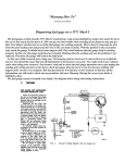
ABRIO Optical Train
White Light
Source
Monochromatic
Light Filter
Circular
Polarizer/Interference
Filter
Polarizer
Circularly Polarized Light
Sample
Quarter Wave
Plate
! = 546
nm
O°
-45°
(",#)
Altered Light
Liquid Crystal
Compensator Optic
Variable
Retarder B
O°
Variable !
Retarder A
+45°
Analyzer
Detector
Computer
ABRIO
Camera
" = retardance [nm]
# = extinction angle
O°