1
LIST OF FIGURES
Page
Figure 2.1: The principal set-up of a typical TSDC experiment......................................................6
Figure 2.2: Proportional band feature of CN63100 controller .........................................................8
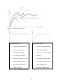
Figure 2.3: Integral time ..................................................................................................................9
Figure 2.4: Derivative time ............................................................................................................10
Figure 2.5: Typical response curve ................................................................................................11
Figure 2.6: Process response extremes ..........................................................................................11
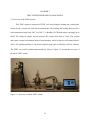
Figure 3.1: Overview of whole TSDC system ...............................................................................12
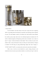
Figure 3.2: TSDC cell ....................................................................................................................14
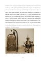
Figure 3.3: 3D design of main chamber and real picture ...............................................................16
Figure 3.4: Dimension of main chamber .......................................................................................16
Figure 3.5: Overview of heating unit .............................................................................................18
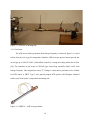
Figure 3.6: OMEGA – AHP series gas heater ...............................................................................18
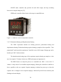
Figure 3.7: OMEGA-CN63100 temperature controller ................................................................20
Figure 3.8: OMEGA-CN63100 temperature controller – SPRP mode diagram ...........................22
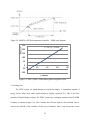
Figure 3.9: TSDC system - SPRP heating mode temperature curve .............................................22
Figure 3.10: Overview of heating unit of TSDC system ..............................................................23
Figure 3.11: Overview of electrical unit of TSDC system ............................................................24
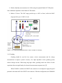
Figure 3.12: Connection diagram between TSDC cell and 6517B meter......................................25
Figure 3.13: Guarding diagram of Keithley 6517B meter .............................................................26
Figure 3.14: Current measurement diagram of Keithley 6517B meter .........................................29
Figure 3.15: Interlock diagram of Keithley 6517B meter..............................................................30
viii