1
ATHENA.4
IJSE,RMANI.]AL
Please read over this manual before operation the
light ( €
1. Must operate according,o,,n"ff3ilIa1"J"'t
separate the light personaily.
Call the technician when the machine breaks down.
2. Please do not see the lasdr beam directly to avoid any damage.
3. Before connect or disconnect the power, please adjust the luminance of the
laser diode to the least to avoid any damage to the laser diode.
4 . This unit should be keep dry, do not use in the rain or dank and dusty
environment. It can be use in the outdoor with the water-proof cover protector.
5. Set the light immobility and try to avoid strong shake or hit.
6. Prevent dust into the equipment to avoid problems.
7 . Please keep that there's no other equipment or decorating materials obstructed
the exhaust fan and the vent-pipe when the equipment was working.
,e,.
8. Before connetöt power, check the plug is immobility or not, power line should
be connect well.
g. Please do not open or close the equipment frequently that's to avoid any affect
to the life span of the laser diode, and try the best to avoid the long time
working.
10. Due to the characteristic of the laser diode, after three hours working, it should
be close at least 25 minutes until the laser diode cooling then work again.
11. Don't touch the light or draw the power line when your hand was wet. And do
not pull the electronic power line,
12. Maintain the distance at least 20M above from the equipment to the object.
13. This equipment does not have any parts can repair for the users, please do not
open the equipment.
14. Don't connect power or operate the light before install lamp.
15. When the laser diode became dim or damaged please contact the dealer timely.
16. To use the original package when transport again and to avoid shake.
17. When use this lamp, you must turn on the lamp at first and then start the
computer .If you open LASERSHOW software before turn on the lamp, please
restart the LASERSHOW software.
Warning
1
.
2.
Don't look the light directly to prevent make some destroy with eyes..
Keep the space between light equipments and the lighted things more than one meter.
1
oPEN
rrip Box FoR cHECKTNG
In order to use this produgt safety and reasonable for the users, please read over
this manual carefully before use and the operation must strictly according to this
manual to avoid any damage to the product and personal safety.
Once after received this products please take and put carefully. And check
carefully that whether the product was damaged or not during the transportation and
please check the following things were enclosed:
Graphics USB card 1PCS
Laser light 1PCS
USB connection cable lPCS
9 pin signal line lPCS
User manual lPCS
3 pin signal line lPCS
Power cable lPCS
25 pin sighal ljae lPCS
Install CD lPCS
INSTALLATION
1. Please check the voltage whether is the same with the one showed
2.
3.
4.
5.
6.
on the
equipment or not.
Itmust ask for the technical person and set the light safety when installation. And
let the light beam at the suitable angle.
When install this equipment please make sure there's no flammable surfaces
(decorated things, etc) within at least 1.5M and maintain minimum distance of
0.5M from the equipment to the walls
Please make sure that there's no other equipment or decorating material,s
obstructed the exhaust fan and the vent-pipe.
Products should be install immobility.
In case of safety, it's very important that to connect the earth with line.
2
&
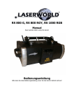
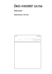
Control Board Instrirction
ffi''""
o'.1
|
o
Qu
%\"";'\
ADORESS
ror[-----l
o[]o
ILDA Da-25F Cohnccto.
CARTOON LASER
-
o[]o
I
o1ö
o
IN
ol
VOLUME
PCSIGNAL-OUT
" of]o
Powcr:?5W
Class I
Lrse. Clsss 38,532nm/300nW
3B,67lnn/450mW
LascrClass 4, 595nn/600nW
Lascr Clsss
((GAATE
W0hin!! Rad
tutEctid
b.forc
ißlltütim
POWER INPUT: Input power, with inner fuse.
PC SIGNAL IN/our: usB connection port signal input/output
DMX IN/OUT: DMX 5 l2 signal input/output
POWER ON/OFF: power on/off
MI'C: Receive Music.
MIN-MAX: Music sensitivity potentiometer
ADDRESS: the 10'o code is switch code. when the l0ü code is oFF, l-9 are
function codes. When function code is 0, the working mode is Music Active
(Master mode); when function code is 1, the working mode is Automatic (Master
mode); when function code is 2 or more, the working mode is Slave mode. When
the 10'o code is ON,1-9 will be DMX address codes. The address code of first
light usually by 1, the second light is l l and so on.
IIDA DB 25 F Connector: signal input connection port of the laser perform
software that in accordance with the ILDA standard.
NOTE:
SIGNAL IN and ILDA DB 25F connector ' s connection port are free,
the lamp will drive by the inside program, temporality it can control by music or
DMX 512 signal.
2.When PC SIGNAL IN connects rvith USB interfacial card, the lamp will be
control by software LASERSHOW which was installed in the computer.
3.After connect the ILDA DB 25F, The lamp will change to IL,DA connected port
drive mode ,this connection port can receive all the signal of laser perform
software that accord with the ILDA standard, such as LD-2000 of pangolin
1. When PC
Company.
4.When the PC SIGNAL IN and the ILDADB 25F Connector were connected, then
the system will at an abnormal statement, lamp still control by inside program
,
but not respond to the exterior input signal.
+
3
DMX512,OPERATE
The product has 10 operate channels(international standard DMX512 signal),The details
as
follow:
DMX512 valu
Channel
Function
1
0-63
64-127
Control Mode
r28-r9t
Music Active,3-7&9-10 channel no valid
Auto Active,3-7&9-10 channel no valid
Manual mode (music active)
192-255
Manual mode (auto active)
0-35
Stochastic single color
Stochastic multiple color
36-tl
2
72-r07
change color
108-143
Fluxion change color
Fixup color
r44-179
Red
1
216-251
252-255
0*255
3 picture
0-63
4
hnriznnfql
80-21 s
,R'
vertical roll
5
Dot rotation
Green
Close
8
6 pictures (0-25 5) I 3:(0-85)
No rolling
64-t27
Horizontal roll
T28*T9I
Vertical roll
t92-2s5
Horizontal & vertical roll
0-127
128-255
0-63
6
Yellow
No rotation
Rotation
No move
64-127
128-191
Horizontal move
192-25s
0-63
64-127
Horizontal & vertical move
vertical stretch
r28-r9r
Verticai stretch
Horizontal & vertical stretch
8 Speed
192-2ss
0-255
ffnriznnfcl
.&
vertical mov(
7
fforiznnfcl
.&
Vertical move
No stretch
Horizontal stretch
12 grade speed(0-255)/23:(0-1 I )
9
Slow-draw
0-255
12 gr
ade speed(0-2
5
speed
L0
Size
0-255
5) I 23
:(0
-l
1)
26 grade size(0-25 5)/ I 0:(0-25)
0 oriqinal size
1-1l"reduce
l2-25bIow up
NOTE:The 8'hchannel can not be 0 in any mode.
4
Specification
Class 3 Red 67lnn/450mW
Class 4 Yellow 595nm/600m W
::'
Maintain
'
a'
)Maintenance should be performed every l5-day period, by using a sponge which is
dipped with alcohol, rather than wet cloth or other chemical liquid, tb clean t[e mirror.
FWarning: Power must be disconnected before maintenance or repair. Do not look at the
lighl source directly.
ATTENTION: DISCONNECT INPUT POWER BEFORE MAINTAIN.
DON'T LOOK STRAIGHTLY AT THE LIGHT SOURCES.
NOTE: Don't seperate laser machine from laser power and repaire them by yourself
otherwise no good repair service
will be supplied.
5
n'nTng'control sYstem
Control software function fast description:
Install with USB interface card, have disconnected drawing and RGB laser beam
control function.
i
2.Canbe installed with Window Me/Window 200O/Window XP operation system.
3.Working in the different sltep (need to install USB assembly-linä device)
4.Can download PLT document by Corel Draw software.
5.Input words by typing directly
6.Disconnected drawing and RGB laser beam
T.Section editing and display function
S.Sequence editing and display function
9.RGB color invert.
1 0.Document operating function
1.
System Requirements
1.
CPU's clock frequency in 1.7GHz or above
2. USB port agree with USB 1.1 agreement
3. 256Mr8 or aboile memory
4. Display'cardmemory is äZNAB or above
5. The available space of HD is l GB or above
6. Window 2000 /Win XP operation sysrem. Higher system will be required if you
want, to control many tights. The operation system is very important for the
working speed of lights.
Drive card program installation:
l.Conne'ct PC, USB interface card and laser light well and then switch on laser light.
2.The system will search installation CD-RöM automatically when it finds iew
hard parts, Select yjlight.inf document from CD-ROM
Application progräm Installation
1.Run setup.exe of CD-ROM to install application program:
Wffi
ffi
rH5T32I_
SETIIP.
ilTS
lErr,$
[#ä,
I
yjJ.oader. sys
SETUP.
6
SXTIIP.
IJ}
Software operation
Please click STAR, PROGRAM, LaserShow and then
'following interface will appear:
I. Main window function:
The button in main window is switch on / off function windows.
1. DRAW: Design and edit basic patterns.
2. PLAY: Display basic patterns by manual.
3. SECTION: Edit the different effect of patterns and make up
basic patterns be cartoon.
4. SEQUENCE: Edit display list and cartoon.
5. FILE: Add or delete basic patterns;
6.
7.
invert blank drawings and
connection drawings.
EXIT: exit system.
The operating way of working in the different step: Plug the
USB integrated device in the USB port of PC and then connect
USB driving card signal lines of each laser light to USB
integrated device. Switch on all laser lights and start up
Application program and choose Usb-0; Start up another
application program and choose Usb-l and so on. Start up
application program for each laser light and then you can
control each light in the different step. (If PC has many
-l USB
ports, you won't need USB integrated äevice).
II. D'raw
7
1. NEW : Click this button to create a new design. Furbish pre-design.
2.OPEN LIB: Click this button and then following dialogue box will appear:
---* -t----- --
-17.ddu !C:\dtu\1l.ddu
\dtu\1I.ddu
i
ddrr
1B.ddu
ic:\dtu\ta.ddu
':: -- : t.-------l---..--"-----------'----'--1
1b.ddu-iCjlot,iii".ao"
iC:\dtu\1b.ddu i
.*--.--*..--...--....-.t...-.*
i;.dd,r
!
*___-__ --__-_--_"_ _ *_"-'-- 1I
-*.--..---.---.-.-...*:*-:-.-i-t--:.:.,1:::___-..-............1
i
\dhr\l R
i
.
1
ld.ddu
ic:\dtuUd.ddu
._.......t:-:.:__:..:. ..::.:
lq,-d{! :9i!-d-!$!s,uay
3d-a-! * jc't!!y:3.d.+ _j
.::
.... ..-.
!
;
i
_.......j
j
20.ddu !c,\dru\ao.ddu-*-i;
ä"ddo'*---j,c\drr;vlJd"
2.1 Click OPEN button, it
will
open the chosen new design. Furbish pre-design.
2.2 Click MERGE button, and then unite the chosen desiln to the pre-design.3. Open; e lick this button to bounce out a window to display all tie recogiized
designs (include all designs out of design file). Select up driver box and directory
list box in the left. Select up breviary design and then recognized designs will be
showed in the right. Use < and > button to turn pages; click the breviäry design
to open this design document, or input file's name in input box, and then click to
open
button.
r
I
4'SAVE AS: Click it and then one save dialogue box will appear. After save
the
design and then it will be added to design file automatic. bnly the document
in
design file can be transferred in section editing.
5'IMPORT: Input HPGL format documents to computer console by CorelDraw.
click it and then dialogue box will appear as following:
5.1Explorer is to select the input document.
5'2Design precision is to confirm picture's precision and points. The
higher
precision and more points means slower displäj speed.
_
size factor: Adjust the size of designs lihe tolerate value usually
i'j9:l*tog
is oK).
6'LII\E:
Select one color from color board, and-then click ttt" iruwlng line
button.
Mouse and cursor are restricted to the white editing district. press tü'e
tert siae or
mouse't'o be gin the first point. After move the mouie, unJift.. .irct
the left side,
between these two points appear a line, continue to click the left side
will draw
line constantly. If need to end the drawing process, it can click tttä.ilniil.y
;f
mouse that there will be a beeline automa-tic upp.uiing from;;;l;"'r
initial place
to the end place to form closed design. Mouse^elimina-tes
-o1r.-Ent restriction,
can move freely. If wanting to draw lines from tft. f u.t
""Jp"f"i, .licking the
LINE button again.
7'MovE: Move th_e design. The moved datum mark is the center mark of drawing
field. The move distanö is confirmed by the coordinate of mouse clicking point
and the value of coordinate of datum mark.
8. scALE: use this button to zoom in or zoom out the design size. The range is
from lyo*500Yo, the tolerate value is 100%. Attention: The operating is
no valid
if it is out of border.
9. ROTATE: Rotate the design from -360' -+360" . Attention: the operating is no
valid if it is out of border.
10' REFRESH: Make the design be blank.
It usually is operated with re-draw
design or to delete background.
11. REDRAW: Redraw the design before refreshing and delete background.
12' H MIRROR:'Copy the design and make the v*ertical perpendicular bisector
draw design area as center. New design connects to old onel
9
-
of
13.V MIRROR: copy the design and make the horizontal perpendicular bisector of
draw design area as center. New design connects to old one.
'14.C MIRROR: click this button and then one dialogue box will appear. Move the
cursor to select copy number. Press OK to confirm your selection and then the
design will be copied. New design connects to old one.
15.MOVE POINT: click thp left side of mouse in design's proper place, select the
point which you want to move and then move the mouse to the target place again,
click the left side of mouse once againto finish the operation.
16,ADD POINT: Via this button can add a point between two points. After olick
this button and then click these two points one by one and tGn move mouse to
move two lines to suitable position to finish the operation. Click the right side of
mouse to cancel the operation.
l7 .DEL POINT: Click delete point in the suitable place of design to finish this
. operation.
lS.REPOSITION: Select one point and then move it to another pointless two
points will be as one point and will move at the same time when you move one of
them.
'
,
-di
19.IMAGE: input pictures to software as model of the drawing design from other
files. Click the button and then one dialogue box will appear. Select suitable file
name and open it, the selected pictures will appear in-design editing area. And
then you can draw thedesign by hand accord the input picture.
20.TEXT IN: Word input. Click this button, a dialogue will appear as follows: can
input three-line words and choose the letterform.
20.1Character width factor: adjust single character width. Chinese wordsl
modulus can choose 10.
20.2drawing crassitude factor: to adjust graphic precision and points. Higher
precision, more points.
21. CH COLOR: select one color in the color board, and then click the button. The
selected line segment will be changed to the selected color.
22. SEL AREA: click the blank and drag out a dashed rectangle, select a needed
operating area.
23. CH COLORA: select one color in color board, and then click it. The selected
line segment will be changed to the selected color.
10
24. N{OVE AREA: Move the point of which was 'bhosen by an area chosen order.
The center of movement is the center of the selected rectangle area. The direction
and distance of movement is same as the mouse action.
25. SCALE AREA: zoom out or zoom in the designs within the selected rectangle
area (from I%-500%).
26. ROTATE AREA: rotate the design within the selected rectangle area (from -
360" -+360" ).
27 .PLAY: display the design in the design drawing area by clicking this button.
28. STOP: stop displaying.
29. INVERT: reverse the design in horizontal direction.
30. RUNNING SPEED:Adjust the displaying speed of scan mirror.
III. Playing
,;.
)f,xllI
@
@
; swffi
gj ffi
LV
mn
[]
SffiTJ A*Ä#F
+
,.a
ta
ERMT RAffiT s.4affi
Tdc dflE
#
''--/i*- i
4
W
\
-{l-
tJ
*
\&
(
\
AJ4 ffiffi
rc
*
lhErStüf,
*
+D
Ägc@rt
cFtss
J4
-a#
,"*
JrÄ
s
*"r%t
/\
&
w
s>
.]-r,*J
l.Breviary design
Include the tolerate list of picture document under c:\dtu.
^ter
page
Every
can show 40 breviary pictures, can turn over pages. Click one breviary
picture, it will be covered red grid after it be selected.
2.Display: display the selected pictures.
(It also can be displayed by double
clicking the breviary picture).
3.Stop: Stop displaying.
4.Reverse: reverse the picture in horizontal direction.
5.Pause : Pause displaying.
6.Rot_speed: Adjust the speed of picture rotating.
7.Slow_ drawing sp: Adjust the drawing speed in gradually drawing pictures.
11
8.Hor_stretch: adjust the speed of picture in horizonial extend.
9.Vert_stretch: adjust the speed of piciure in vertical extend.
10. gobo_size: adjustpicture size, the value in20 is the original size; the value in
0
becomes the zoom effect. i
11. Ifor_turn sp: adjust the speed of picture when rolling around the vertical lines.
T2. Yert_turn_sp: adjust thq speed of picture when rolling around the level lines.
13. Hor move sp: adjust thö speed of picture when moving in horizontal direction.
I4. Yerl-tooo1.p: adjust the speed of picture when moving in vertical direction.
15. Running speed: adjust the displaying speed of scan shaking-mirror.
16. Auto: Display with the color of drawing
17. Green: display with green.
18. B lue: display with blue.
19. Red: display with red.
20. Purple: display with purple.
21. Yellow: display with yellow.
22. Aqua: display withAqua.
23. White: display-=,with white.
24. None: Black-out
IV. Section
l.Section is one display unit which is made up of several display designs. It
includes the setting of designs, display time, color and design change speed and etc.
2.New: create anew section. Click addbutton and then will appear a dialogue box.
Start the editing after input and confirm the section name. Add and edit the effect
of patterns.
12
3.Edit: open the selected section in section list
and thön enter the editing mode.
4.Delete: delete the opened section in editing bondition.
5.Rename: rename the display sectionwhile editing.
6.Playing time: Set the time of,design display. The unit is millisecond.
7.The filnction of rotate speed, gradual drawing speed, horizontal extend, vertical
extend, picture size, horizgntal rotate, vertical rotate, horizontal move, vertical
move, and circulating speed track are the same as the last chapter.
S.Color board: All function of color adjustment is the same as the last chapter while
displaying designs. If the color board is automatic while sequence displäying, the
color will be set by color. If color board is not automatic, the color of laser beam
will be controlled by color board.
g.Add: add one line in section content under editing condition. This line's rotate
speed, drawing speed, horizontal rotate, vertical rotate, horizontal move, vertical
move, displaying speed, horizontal extend, vertical extend, size and field are
decided by the value of trackwhichhas been describedby the 7*h contents and the
color field is decide by color board.
;e'
10. Remove:Move;outihe line of section contentwhile editing.
11. Display design; Displaying the design of display list. Thätrack value has been
described by the 7'h contents decide change effects. Color is set on color board,
12.Play D: Displaying the selected section. The section details decide change
effects. Color is set on color board.
13. Circulating mark: Circulating displaying or not.
14. Reverse: The horizontal in anti-direction while Displaying design or seCtion.
15. Stop: stop any display.
16. Pause: Maintain the present condition of designs, no change.
V. Sequence
Editing
13
l.Sequence is displaying unit which is made up of several sections with regulated
displaying time of each section
2. New: create a new sequence. Click it and then will appear a dialogue box. Start
the editing after input and bonfirm the sequence name. Add the seition and edit
the displaying time.
3. Edit: Open the selected srequence, or adjust the displaying sequence into editing
condition.
4. Delete: delete the opened sequence while editing.
5. Rename: rename the display sequence while editing.
6. Sequence list: display the selected sequence.
7. The function of circulating mark, anti-direction, pause and color board is the
same as the pre-chapter.
8. Position: adjust the central position of display.
9' Add: Add one line in the sequence, the displaying time will
be set under section
display time..
10'remove: remove the present line of sequence content while editing.
l l.setting time: tlrag träck, set time and then ctick the button to disp"lay. tf tirdiime
setting has been finished, the display will automatically stops, ör it can cancel
the time setting in the middle of time setting.
VI. File
111111.DDU
II112.DDU
rlr1l3.DDU
111 1
1
4.DDU
I t 1r s.DDU
'II116.DDU
I
ll
rr
l 17.DDU
l'l2l.DDU
'lt 1122.DOU
111123.DDU
l.Add or move out patterns from storage. or change the format.
2.Add: Add patterns to pattern storage.
3.Remove: move out patterns from storage. The patterns have been used in sequence
cannot be moved out.
4.Delete: Delete the selected documents from list.
5.Refresh: Refresh file list.
14
Appendix:
ILDA DB 25F PINOUTS DB 25 definens
2
X+
Y+
-5 to +5V
-5 to +5V
3
IntensityiBlanking*
0V
4
lnterlock A
Connected to pin 17 inside the Qm2000
5
Red*
0V to +2.5V
6
Green*
0V to +2.5V
7
Blue*
0V to +2.5V
8
Deep
9
Yellow*
0V to +2.5V
10
Cyanf
0V to +2.5V
11
Z+
Depth Z(not intensity), -5 to
t2
Not connected
13
Shutter
0V to +5V
t5
XY-
-5V to *5V
-5V to *5V
16
IntensityiBlanking-
-2.5V to 0V
l7
lnterlock B
Connected to pin
18
Red-
-2.5V to 0V
19
Green-
-2.5V to 0V
-2.5V to 0V
22
BlueDeep blueYellow-
23
Cyan-
24
Z-
25
Ground
I
t4
20
2l
blue*
to +2.5V
0V to +2.5V
+5V
4 inside the Qm2000
-2.5V to 0V
-2.5V to 0V
-2.5V to 0V
-5V to +5V
Cable shield
yERS/ON 7.0
15