1
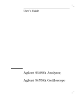
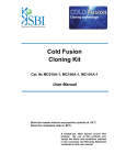
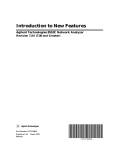
Figure 6-77. Combined Eects of Amplitude and Phase Modulation
Using the demodulation capabilities of the analyzer, it is possible to view the amplitude or
the phase component of the modulation separately. The window menu includes the following
softkeys to control the demodulation feature:
is the normal preset state, in which both the amplitude and phase components
DEMOD: OFF
of any test device modulation appear on the display.
displays only the amplitude modulation, as illustrated in Figure 6-78a.
AMPLITUDE
NNNNNNNNNNNNNNNNNNNNNNNNNNNNNNNN
NNNNNNNNNNNNNNNNNNNNNNNNNNNNN
NNNNNNNNNNNNNNNNN
PHASE
displays only the phase modulation, as shown in Figure 6-78b.
Figure 6-78.
Separating the Amplitude and Phase Components of Test-Device-Induced Modulation
Forward transform range. In the forward transform (from CW time to the frequency domain),
range is dened as the frequency span that can be displayed before aliasing occurs, and is
similar to range as dened for time domain measurements. In the range formula, substitute
time span for frequency span.
Example:
6-136 Application and Operation Concepts