1
Agilent 4396B Network/Spectrum/Impedance Analyzer Function Reference
Manual Change
Agilent Part No. N/A
Feb 2008
Change 1
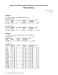
Change the specification of L Accuracy (Page 11-19) to the following.
Accuracy
D ≦ 0.2
0.2 < D
La
La
La(1 + D)
C Copyright 2008 Agilent Technologies
○
マニュアル チェンジ
変更 1
L Accuracy の仕様(ページ 11-19)を以下に変更して下さい。
Accuracy
D ≦ 0.2
0.2 < D
La
La
La(1 + D)
C Copyright 2008 Agilent Technologies
○
Agilent 4396B Network/Spectrum/Impedance Analyzer Function Reference
Manual Change
Agilent Part No. N/A
January 2007
Change 1
Add the following temperature condition to other spurious of the spurious responses (on page 10-11).
@ -30 dBm mixer input, offset ≧ 1 kHz, 23±5℃...
.
..
..
..
..
..
.
.<-70 dBc
マニュアル チェンジ
変更 1
スプリアス・レスポンスのスプリアス(ページ 10-11)に温度条件を追加して下さい。
@ミキサ入力-30 dBm, オフセット ≧ 1 kHz, 23±5℃ ...
.
..
..
..
..
..<-70 dBc
C Copyright 2007 Agilent Technologies
○
Manual Change
Agilent Part No. N/A
August 2004
Printed in Malaysia
Change
Change the company name from (YOKOGAWA-) HEWLETT-PACKARD, LTD., or its abbreviation HP
(YHP) to Agilent Technologies or Agilent.
This document may contain references to HP (YHP) or (Yokogawa-) Hewlett-Packard.
Please note that
Hewlett-Packard’s former test and measurement, semiconductor products and chemical analysis businesses
are now part of Agilent Technologies.
To reduce potential confusion, the only change to product numbers
and names has been in the company name prefix: where a product number/name was HP XXXX the current
name/number is now Agilent XXXX. For example, model number HP4294A is now model number Agilent
4294A.
マニュアル・チェンジ
変更
本文中の「HP(YHP)」、または「(横河)ヒューレット・パッカード株式会社」という語句を、「Agilent」、
または「アジレント・テクノロジー株式会社」と変更してください。
ヒューレット・パッカード社の電子計測、半導体製品、化学分析ビジネス部門は分離独立し、アジ
レント・テクノロジー社となりました。
社名変更に伴うお客様の混乱を避けるため、製品番号の接頭部のみ変更しております。
(例: 旧製品名
HP 4294A
© Copyright 2004 Agilent Technologies
は、現在
Agilent 4294A
として販売いたしております。)
Safety Notification
This product is tested with stand-alone condition or with the combination with the
accessories supplied by Agilent Technologies against the requirements of the standards
described in the Declaration of Conformity. If it is used as a system component,
compliance of related regulations and safety requirements are to be confirmed by the
builder of the system.
Caution
Do not exceed the operating input power, voltage, and current
level and signal type appropriate for the instrument being used, refer to
your instrument's Function Reference.
Electrostatic discharge(ESD) can damage the highly sensitive
microcircuits in your instrument. ESD damage is most likely to occur as
the test fixtures are being connected or disconnected. Protect them from
ESD damage by wearing a grounding strap that provides a high
resistance path to ground. Alternatively, ground yourself to discharge any
static charge built-up by touching the outer shell of any grounded
instrument chassis before touching the test port connectors..
4396B
Notice
The information contained in this document is subject to change
without notice.
This document contains proprietary information that is protected by
copyright. All rights are reserved. No part of this document may be
photocopied, reproduced, or translated to another language without
the prior written consent of the Agilent Technologies.
Agilent Technologies Japan, Ltd.
Component Test PGU-Kobe
1-3-2, Murotani, Nishi-ku, Kobe-shi,
Hyogo, 651-2241 Japan
c Copyright 1997, 1998, 2000, 2002, 2003
Agilent Technologies Japan, Ltd.
Manual Printing History
The manual printing date and part number indicate its current
edition. The printing date changes when a new edition is printed.
(Minor corrections and updates that are incorporated at reprint do not
cause the date to change.) The manual part number changes when
extensive technical changes are incorporated.
March 1997 : : : : : : : : : : : : : : : : First Edition (part number: 04396-90020)
July 1997 : : : : : : : : : : : : : : : Second Edition (part number: 04396-90032)
September 1997 : : : : : : : : : : Third Edition (part number: 04396-90042)
September 1998 : : : : : : : : : Fourth Edition (part number: 04396-90052)
March 2000 : : : : : : : : : : : : : : : Fifth Edition (part number: 04396-90052)
November 2002 : : : : : : : : : : : Sixth Edition (part number: 04396-90062)
May 2003 : : : : : : : : : : : : : : Seventh Edition (part number: 04396-90072)
iii
Certication
Warranty
Agilent Technologies certies that this product met its published
specications at the time of shipment from the factory. Agilent
Technologies further certies that its calibration measurements are
traceable to the United States National Institute of Standards and
Technology, to the extent allowed by the Institution's calibration
facility, or to the calibration facilities of other International Standards
Organization members.
This Agilent Technologies instrument product is warranted against
defects in material and workmanship for a period of one year from
the date of shipment, except that in the case of certain components
listed in General Information of this manual, the warranty shall
be for the specied period. During the warranty period, Agilent
Technologies will, at its option, either repair or replace products that
prove to be defective.
For warranty service or repair, this product must be returned to a
service facility designated by Agilent Technologies. Buyer shall prepay
shipping charges to Agilent Technologies and Agilent Technologies
shall pay shipping charges to return the product to Buyer. However,
Buyer shall pay all shipping charges, duties, and taxes for products
returned to Agilent Technologies from another country.
Agilent Technologies warrants that its software and rmware
designated by Agilent Technologies for use with an instrument will
execute its programming instruction when property installed on that
instrument. Agilent Technologies does not warrant that the operation
of the instrument, or software, or rmware will be uninterrupted or
error free.
Limitation Of Warranty
The foregoing warranty shall not apply to defects resulting from
improper or inadequate maintenance by Buyer, Buyer-supplied
software or interfacing, unauthorized modication or misuse,
operation outside the environmental specications for the product, or
improper site preparation or maintenance.
No other warranty is expressed or implied. Agilent Technologies
specically disclaims the implied warranties of merchantability and
tness for a particular purpose.
iv
Exclusive Remedies
Assistance
The remedies provided herein are buyer's sole and exclusive
remedies. Agilent Technologies shall not be liable for any direct,
indirect, special, incidental, or consequential damages, whether based
on contract, tort, or any other legal theory.
Product maintenance agreements and other customer assistance
agreements are available for Agilent Technologies products.
For any assistance, contact your nearest Agilent Technologies Sales
and Service Oce. Addresses are provided at the back of this manual.
v
Safety Summary
The following general safety precautions must be observed during all
phases of operation, service, and repair of this instrument. Failure to
comply with these precautions or with specic WARNINGS elsewhere
in this manual may impair the protection provided by the equipment.
In addition it violates safety standards of design, manufacture, and
intended use of the instrument.
The Agilent Technologies assumes no liability for the customer's
failure to comply with these requirements.
Note
4396B comply with INSTALLATION CATEGORY II and POLLUTION
DEGREE 2 in IEC1010-1. 4396B are INDOOR USE product.
Note
LEDs in this product are Class 1 in accordance with IEC825-1.
CLASS 1 LED PRODUCT
Ground The Instrument
To avoid electric shock hazard, the instrument chassis and cabinet
must be connected to a safety earth ground by the supplied power
cable with earth blade.
DO NOT Operate In An Explosive Atmosphere
Do not operate the instrument in the presence of ammable gasses or
fumes. Operation of any electrical instrument in such an environment
constitutes a denite safety hazard.
Keep Away From Live Circuits
Operating personnel must not remove instrument covers. Component
replacement and internal adjustments must be made by qualied
maintenance personnel. Do not replace components with the power
cable connected. Under certain conditions, dangerous voltages may
exist even with the power cable removed. To avoid injuries, always
disconnect power and discharge circuits before touching them.
DO NOT Service Or Adjust Alone
Do not attempt internal service or adjustment unless another person,
capable of rendering rst aid and resuscitation, is present.
DO NOT Substitute Parts Or Modify Instrument
Because of the danger of introducing additional hazards, do not
install substitute parts or perform unauthorized modications to the
instrument. Return the instrument to a Agilent Technologies Sales and
Service Oce for service and repair to ensure that safety features are
maintained.
vi
Dangerous Procedure Warnings
Warnings , such as the example below, precede potentially dangerous
procedures throughout this manual. Instructions contained in the
warnings must be followed.
Warning
Dangerous voltages, capable of causing death, are present in this
instrument. Use extreme caution when handling, testing, and
adjusting this instrument.
vii
Safety Symbols
General denitions of safety symbols used on equipment or in manuals
are listed below.
Instruction manual symbol: the product is marked
with this symbol when it is necessary for the user to
refer to the instruction manual.
Alternating current.
Direct current.
On (Supply).
O (Supply).
In position of push-button switch.
Out position of push-button switch.
Frame (or chassis) terminal. A connection to the
frame (chassis) of the equipment which normally
include all exposed metal structures.
This Warning sign denotes a hazard. It calls
attention to a procedure, practice, condition or the
like, which, if not correctly performed or adhered to,
could result in injury or death to personnel.
This Caution sign denotes a hazard. It calls attention
to a procedure, practice, condition or the like, which,
if not correctly performed or adhered to, could result
in damage to or destruction of part or all of the
product.
This Note sign denotes important information. It
calls attention to a procedure, practice, condition or
the like, which is essential to highlight.
Axed to product containing static sensitive devices
use anti-static handling procedures to prevent
electrostatic discharge damage to component.
viii
Typeface Conventions
Bold
Italics
Computer
4HARDKEYS5
NNNNNNNNNNNNNNNNNNNNNNNNNN
SOFTKEYS
Boldface type is used when a term is dened.
For example: icons are symbols.
Italic type is used for emphasis and for titles
of manuals and other publications.
Italic type is also used for keyboard entries
when a name or a variable must be typed in
place of the words in italics. For example:
copy lename means to type the word copy,
to type a space, and then to type the name of
a le such as file1.
Computer font is used for on-screen prompts
and messages.
Labeled keys on the instrument front panel
are enclosed in 4 5.
Softkeys located to the right of the CRT are
enclosed in .
NNNNN
ix
Documentation Map
The following manuals are available for the analyzer.
User's Guide (Agilent Part Number 04396-900x1 1 )
The User's Guide walks you through system setup and initial power-on, shows how to
make basic measurements, explains commonly used features, and typical application
measurement examples. After you receive your analyzer, begin with this manual.
Task Reference (Agilent Part Number 04396-900x0 1)
Task Reference helps you to learn how to use the analyzer. This manual provides simple
step-by-step instructions without concepts.
Function Reference (Agilent Part Number 04396-900x2 1 )
The Function Reference describes all function accessed from the front panel keys and
softkeys. It also provides information on options and accessories available, specications,
system performance, and some topics about the analyzer's features.
Programming Guide (Agilent Part Number 04396-900x3 1 )
The Programming Guide shows how to write and use BASIC program to control the
analyzer and describes how Instrument BASIC works with the analyzer..
GPIB Command Reference (Agilent Part Number 04396-900x4 1)
The GPIB Command Reference provides a summary of all available GPIB commands. It
also provides information on the status reporting structure and the trigger system (these
features conform to the SCPI standard).
Option 010 Operating Handbook (Agilent Part Number 04396-900x6 1 )
The option 010 Operation Handbook describes the unique impedance measurement
functions of the 4396B with option 010.
Instrument BASIC Manual Set (Agilent Part Number 04155-90151(E2083-90000))
The Instrument BASIC User's Handbook introduces you to the Instrument BASIC
programming language, provide some helpful hints on getting the most use from it, and
provide a general programming reference. It is divided into three books, Instrument
BASIC Programming Techniques, Instrument BASIC Interface Techniques, and
Instrument BASIC Language Reference.
Performance Test Manual (Agilent Part Number 04396-901x0 1 )
The Performance Test Manual explains how to verify conformance to published
specications.
Service Manual (Agilent Part Number 04396-901x1 1 )
The Service Manual explains how to adjust, troubleshoot, and repair the instrument.
This manual is option 0BW only.
1 The number indicated by \x" in the part number of each manual, is allocated for numbers increased by one each
time a revision is made. The latest edition comes with the product.
x
Contents
1. Introduction
Analyzer's Features . . . . .
Front and Rear Panel . . .
ACTIVE CHANNEL Block .
ENTRY Block . . . . . . .
MEASUREMENT Block . . .
Network Analyzer Mode .
Spectrum Analyzer Mode .
SWEEP Block . . . . . . .
MARKER Block . . . . . .
INSTRUMENT STATE Block
.
.
.
.
.
.
.
.
.
.
.
.
.
.
.
.
.
.
.
.
.
.
.
.
.
.
.
.
.
.
.
.
.
.
.
.
.
.
.
.
.
.
.
.
.
.
.
.
.
.
.
.
.
.
.
.
.
.
.
.
.
.
.
.
.
.
.
.
.
.
.
.
.
.
.
.
.
.
.
.
.
.
.
.
.
.
.
.
.
.
.
.
.
.
.
.
.
.
.
.
.
.
.
.
.
.
.
.
.
.
.
.
.
.
.
.
.
.
.
.
.
.
.
.
.
.
.
.
.
.
.
.
.
.
.
.
.
.
.
.
.
.
.
.
.
.
.
.
.
.
.
.
.
.
.
.
.
.
.
.
.
.
.
.
.
.
.
.
.
.
.
.
.
.
.
.
.
.
.
.
.
.
.
.
.
.
.
.
.
.
.
.
.
.
.
.
.
.
.
.
.
.
.
.
.
.
.
.
.
.
.
.
.
.
.
.
.
.
.
.
.
.
.
.
.
.
.
.
.
.
1-1
1-1
1-1
1-1
1-2
1-2
1-2
1-3
1-3
1-3
Front Panel . . . . . . . . . . . . . . . . . . . .
1. Front Panel Keys and Softkeys . . . . . . . . .
Softkeys that are Joined by Vertical Lines . . . .
Softkeys That Toggle On or O . . . . . . . . .
Softkeys that Show Status Indications in Brackets
2. GPIB \REMOTE" Indicator . . . . . . . . . . .
3. 4Preset5 . . . . . . . . . . . . . . . . . . . .
4. PROBE POWER Connector . . . . . . . . . . .
5. Network Analyzer Inputs R, A, and B . . .
6. RF OUT Connector . . . . . . . . . . . . . .
7. Spectrum Analyzer Input S . . . . . . . .
8. CAL OUT Connector . . . . . . . . . . . . .
9. Built-in Flexible Disk Drive . . . . . . . . . .
10. LINE Switch . . . . . . . . . . . . . . . . .
Screen display . . . . . . . . . . . . . . . . . . .
1. Active Channel . . . . . . . . . . . . . . . .
2. Measured Input(s) . . . . . . . . . . . . . . .
3. Format . . . . . . . . . . . . . . . . . . . .
4. Scale/Div . . . . . . . . . . . . . . . . . . .
5. Reference Level . . . . . . . . . . . . . . .
6. Marker Data Readout . . . . . . . . . . . . .
7. Marker Statistics and Width Value . . . . . . .
8. Softkey Labels . . . . . . . . . . . . . . . .
9. Pass/Fail . . . . . . . . . . . . . . . . . . .
10. Sweep Time . . . . . . . . . . . . . . . . .
11. Sweep Parameter Span/Stop Value . . . . . .
12. Power Level . . . . . . . . . . . . . . . . .
13. CW Frequency . . . . . . . . . . . . . . . .
14. Video Bandwidth (VBW) . . . . . . . . . . .
15. Input Attenuator . . . . . . . . . . . . . .
16. Sweep Parameter Center/Start Value . . . . .
.
.
.
.
.
.
.
.
.
.
.
.
.
.
.
.
.
.
.
.
.
.
.
.
.
.
.
.
.
.
.
.
.
.
.
.
.
.
.
.
.
.
.
.
.
.
.
.
.
.
.
.
.
.
.
.
.
.
.
.
.
.
.
.
.
.
.
.
.
.
.
.
.
.
.
.
.
.
.
.
.
.
.
.
.
.
.
.
.
.
.
.
.
.
.
.
.
.
.
.
.
.
.
.
.
.
.
.
.
.
.
.
.
.
.
.
.
.
.
.
.
.
.
.
.
.
.
.
.
.
.
.
.
.
.
.
.
.
.
.
.
.
.
.
.
.
.
.
.
.
.
.
.
.
.
.
.
.
.
.
.
.
.
.
.
.
.
.
.
.
.
.
.
.
.
.
.
.
.
.
.
.
.
.
.
.
.
.
.
.
.
.
.
.
.
.
.
.
.
.
.
.
.
.
.
.
.
.
.
.
.
.
.
.
.
.
.
.
.
.
.
.
.
.
.
.
.
.
.
.
.
.
.
.
.
.
.
.
.
.
.
.
.
.
.
.
.
.
.
.
.
.
.
.
.
.
.
.
.
.
.
.
.
.
.
.
.
.
.
.
.
.
.
.
.
.
.
.
.
.
.
.
.
.
.
.
.
.
.
.
.
.
.
.
.
.
.
.
.
.
.
.
.
.
.
.
.
.
.
.
.
.
.
.
.
.
.
.
.
.
.
.
.
.
.
.
.
.
.
.
.
.
.
.
.
.
.
.
.
.
.
.
.
.
.
.
.
.
.
.
.
.
.
.
.
.
.
.
.
.
.
.
.
.
.
.
.
.
.
.
.
.
.
.
.
.
.
.
.
.
.
.
.
.
.
.
.
.
.
.
.
.
.
.
.
.
.
.
.
.
.
.
.
2-1
2-2
2-2
2-2
2-2
2-2
2-3
2-3
2-3
2-3
2-3
2-4
2-4
2-4
2-4
2-5
2-6
2-6
2-6
2-6
2-6
2-6
2-6
2-7
2-7
2-7
2-7
2-7
2-7
2-7
2-7
2. Front and Rear Panel
.
.
.
.
.
.
.
.
.
.
Contents-1
17. RBW/IFBW . . . . . . . . . . .
18. Status Notations . . . . . . . . .
19. External Reference . . . . . . .
20. Active Entry Area . . . . . . . .
21. Message Area . . . . . . . . . .
22. Title . . . . . . . . . . . . . .
Rear Panel Features and Connectors . .
1. External Reference Input . . . . .
2. Internal Reference Output . . . . .
3. External Program RUN/CONT Input
4. I/O Port . . . . . . . . . . . . .
5. Power . . . . . . . . . . . . . .
6. GPIB Interface . . . . . . . . . .
7. External Monitor Terminal . . . . .
8. Parallel Interface . . . . . . . . .
9. mini DIN Keyboard Connector . . .
.
.
.
.
.
.
.
.
.
.
.
.
.
.
.
.
.
.
.
.
.
.
.
.
.
.
.
.
.
.
.
.
.
.
.
.
.
.
.
.
.
.
.
.
.
.
.
.
.
.
.
.
.
.
.
.
.
.
.
.
.
.
.
.
.
.
.
.
.
.
.
.
.
.
.
.
.
.
.
.
.
.
.
.
.
.
.
.
.
.
.
.
.
.
.
.
.
.
.
.
.
.
.
.
.
.
.
.
.
.
.
.
.
.
.
.
.
.
.
.
.
.
.
.
.
.
.
.
.
.
.
.
.
.
.
.
.
.
.
.
.
.
.
.
.
.
.
.
.
.
.
.
.
.
.
.
.
.
.
.
.
.
.
.
.
.
.
.
.
.
.
.
.
.
.
.
.
.
.
.
.
.
.
.
.
.
.
.
.
.
.
.
.
.
.
.
.
.
.
.
.
.
.
.
.
.
.
.
.
.
.
.
.
.
.
.
.
.
.
.
.
.
.
.
.
.
.
.
.
.
.
.
.
.
.
.
.
.
.
.
.
.
.
.
.
.
.
.
.
.
.
.
.
.
.
.
.
.
.
.
.
.
.
.
.
.
.
.
.
.
.
.
.
.
.
.
.
.
.
.
.
.
.
.
.
.
.
.
.
.
.
.
.
.
.
.
.
.
.
.
.
.
.
.
2-7
2-8
2-8
2-9
2-9
2-9
2-9
2-10
2-10
2-10
2-10
2-10
2-10
2-10
2-10
2-11
10. Test Set I/O Interface . . . . . . .
Gate Output (Option 1D6 Only) . . . . .
External Trigger Input . . . . . . . . .
2nd IF Output . . . . . . . . . . . . .
Reference Oven Output (Option 1D5 Only)
.
.
.
.
.
.
.
.
.
.
.
.
.
.
.
.
.
.
.
.
.
.
.
.
.
.
.
.
.
.
.
.
.
.
.
.
.
.
.
.
.
.
.
.
.
.
.
.
.
.
.
.
.
.
.
.
.
.
.
.
.
.
.
.
.
.
.
.
.
.
.
.
.
.
.
.
.
.
.
.
2-11
2-11
2-11
2-11
2-11
(CHAN1) and 4Chan 25 (CHAN2) . . . . . . . . . . . . . . . . . . . . . .
Coupling Channels . . . . . . . . . . . . . . . . . . . . . . . . . . . . .
3-1
3-1
11.
12.
13.
14.
3. Active Channel Block
4Chan 15
4. Entry Block
Numeric Keypad . .
Terminator Keys . .
Knob . . . . . . .
4*5 and 4+5 . . . . .
4Entry O5 (KEY 18) .
4Back Space5 (KEY 19)
.
.
.
.
.
.
.
.
.
.
.
.
.
.
.
.
.
.
.
.
.
.
.
.
.
.
.
.
.
.
.
.
.
.
.
.
.
.
.
.
.
.
.
.
.
.
.
.
.
.
.
.
.
.
.
.
.
.
.
.
.
.
.
.
.
.
.
.
.
.
.
.
.
.
.
.
.
.
.
.
.
.
.
.
.
.
.
.
.
.
.
.
.
.
.
.
.
.
.
.
.
.
.
.
.
.
.
.
.
.
.
.
.
.
.
.
.
.
.
.
.
.
.
.
.
.
.
.
.
.
.
.
.
.
.
.
.
.
.
.
.
.
.
.
.
.
.
.
.
.
.
.
.
.
.
.
.
.
.
.
.
.
.
.
.
.
.
.
4-1
4-2
4-2
4-2
4-2
4-2
. . . . . . . . . . . . . . . . . . . . . . . .
5-3
.
.
.
.
.
.
.
.
.
.
.
.
.
.
.
.
.
.
.
.
5-5
5-5
5-5
5-5
5-5
5-5
5-5
5-5
5-5
5-5
. . . . . . . . . . . . . . . . . . . . . . . .
. . . . . . . . . . . . . . . . . . . . . . . .
Refl: FWD S11 [A/R] (MEAS S11) . . . . . . . . . . . . . . . . . . .
5-6
5-6
5-6
5. Measurement Block
. . . . . . . . . . . .
Input port menu
. . . . .
Network Analyzer
network measurement . .
NETWORK: A/R (MEAS AR)
B/R (MEAS BR) . . . . .
R (MEAS R) . . . . . . .
A (MEAS A) . . . . . . .
B (MEAS B) . . . . . . .
CONVERSION [OFF] . . .
S-PARAMETERS . . . . .
ANALYZER TYPE . . . . .
S-parameter menu
. . . . .
Network Analyzer
4Meas5
NNNNNNNNNNNNNNNNNNNNNNNNNNNNNNNNNNNNNN
NNNNNNNNNNN
NNNNN
NNNNN
NNNNN
NNNNNNNNNNNNNNNNNNNNNNNNNNNNNNNNNNNNNNNNNNNNNNNNNN
NNNNNNNNNNNNNNNNNNNNNNNNNNNNNNNNNNNNNN
NNNNNNNNNNNNNNNNNNNNNNNNNNNNNNNNNNNNNNNNN
s-parameter measurement
NNNNNNNNNNNNNNNNNNNNNNNNNNNNNNNNNNNNNNNNNNNNNNNNNNNNNNNNNNN
Contents-2
.
.
.
.
.
.
.
.
.
.
.
.
.
.
.
.
.
.
.
.
.
.
.
.
.
.
.
.
.
.
.
.
.
.
.
.
.
.
.
.
.
.
.
.
.
.
.
.
.
.
.
.
.
.
.
.
.
.
.
.
.
.
.
.
.
.
.
.
.
.
.
.
.
.
.
.
.
.
.
.
.
.
.
.
.
.
.
.
.
.
.
.
.
.
.
.
.
.
.
.
.
.
.
.
.
.
.
.
.
.
.
.
.
.
.
.
.
.
.
.
.
.
.
.
.
.
.
.
.
.
.
.
.
.
.
.
.
.
.
.
.
.
.
.
.
.
.
.
.
.
.
.
.
.
.
.
.
.
.
.
.
.
.
.
.
.
.
.
.
.
.
.
.
.
.
.
.
.
.
.
.
.
.
.
.
.
.
.
.
.
.
.
.
.
.
.
.
.
.
.
.
.
.
.
.
.
.
.
.
.
.
.
.
.
.
.
.
.
.
.
.
.
.
.
.
.
NNNNNNNNNNNNNNNNNNNNNNNNNNNNNNNNNNNNNNNNNNNNNNNNNNNNNNNNNNN
Trans:FWD S21 [B/R] (MEAS S21)
Trans:REV S12 [B/R] (MEAS S12)
Refl: REV S22 [A/R] (MEAS S22)
CONVERSION [ ] . . . . . . . . .
INPUT PORTS . . . . . . . . . . .
ANALYZER TYPE . . . . . . . . . .
Input port menu
Spectrum Analyzer . . . . . . . . . .
input ports . . . . . . . . . . . . .
SPECTRUM: S (MEAS S) . . . . . .
R (MEAS R) . . . . . . . . . . . .
A (MEAS A) . . . . . . . . . . . .
B (MEAS B) . . . . . . . . . . . .
DETECTION [ ] . . . . . . . . . .
ANALYZER TYPE . . . . . . . . . .
Analyzer type menu
NNNNNNNNNNNNNNNNNNNNNNNNNNNNNNNNNNNNNNNNNNNNNNNNNNNNNNNNNNN
NNNNNNNNNNNNNNNNNNNNNNNNNNNNNNNNNNNNNNNNNNNNNNNNNNNNNNNNNNN
NNNNNNNNNNNNNNNNNNNNNNNNNNNNNNNNNNNNNNNNNNNN
NNNNNNNNNNNNNNNNNNNNNNNNNNNNNNNNNNN
NNNNNNNNNNNNNNNNNNNNNNNNNNNNNNNNNNNNNNNNN
NNNNNNNNNNNNNNNNNNNNNNNNNNNNNNNNNNN
NNNNN
NNNNN
NNNNN
NNNNNNNNNNNNNNNNNNNNNNNNNNNNNNNNNNNNNNNNN
NNNNNNNNNNNNNNNNNNNNNNNNNNNNNNNNNNNNNNNNN
Network Analyzer
. . . . . .
.
.
.
SPECTRUM ANALYZER (SA)
Conversion menu
. . . . . .
Network Analyzer
OFF (CONV OFF) . . . . .
impedance . . . . . . . . .
Z:Refl (CONV ZREF) . . .
Z:Trans (CONV ZTRA) . .
admittance . . . . . . . . .
Y:Refl (CONV YREF) . . .
Y:Trans (CONV YTRA) . .
1/S (CONV ONEDS) . . . .
multiple phase . . . . . . .
4xPHASE (CONV MP4) . . .
8xPHASE (CONV MP8) . . .
16xPHASE (CONV MP16) .
Detection menu
Spectrum Analyzer . . . . . .
positive peak . . . . . . . .
POS PEAK (DET POS) . . .
negative peak . . . . . . .
NEG PEAK (DET NEG) . . .
sample . . . . . . . . . . .
SAMPLE (DET SAM) . . . .
4Format5 . . . . . . . . . . . .
Format menu
. . . . . .
Network Analyzer
log magnitude . . . . . . .
network analyzer . . . .
NETWORK ANALYZER (NA)
spectrum analyzer . . . .
Spectrum Analyzer
NNNNNNNNNNNNNNNNNNNNNNNNNNNNNNNNNNNNNNNNNNNNNNNNNN
NNNNNNNNNNNNNNNNNNNNNNNNNNNNNNNNNNNNNNNNNNNNNNNNNNNNN
NNNNNNNNNNN
NNNNNNNNNNNNNNNNNNNN
NNNNNNNNNNNNNNNNNNNNNNN
NNNNNNNNNNNNNNNNNNNN
NNNNNNNNNNNNNNNNNNNNNNN
NNNNNNNNNNN
NNNNNNNNNNNNNNNNNNNNNNN
NNNNNNNNNNNNNNNNNNNNNNN
NNNNNNNNNNNNNNNNNNNNNNNNNN
NNNNNNNNNNNNNNNNNNNNNNNNNN
NNNNNNNNNNNNNNNNNNNNNNNNNN
NNNNNNNNNNNNNNNNNNNN
.
.
.
.
.
.
.
.
.
.
.
.
.
.
.
.
.
.
.
.
.
.
.
.
.
.
.
.
.
.
.
.
.
.
.
.
.
.
.
.
.
.
.
.
.
.
.
.
.
.
.
.
.
.
.
.
.
.
.
.
.
.
.
.
.
.
.
.
.
.
.
.
.
.
.
.
.
.
.
.
.
.
.
.
.
.
.
.
.
.
.
.
.
.
.
.
.
.
.
.
.
.
.
.
.
.
.
.
.
.
.
.
.
.
5-6
5-6
5-6
5-6
5-6
5-6
.
.
.
.
.
.
.
.
.
.
.
.
.
.
.
.
.
.
.
.
.
.
.
.
.
.
.
.
.
.
.
.
.
.
.
.
.
.
.
.
.
.
.
.
.
.
.
.
.
.
.
.
.
.
.
.
.
.
.
.
.
.
.
.
.
.
.
.
.
.
.
.
.
.
.
.
.
.
.
.
.
.
.
.
.
.
.
.
.
.
.
.
.
.
.
.
.
.
.
.
.
.
.
.
.
.
.
.
.
.
.
.
.
.
.
.
.
.
.
.
.
.
.
.
.
.
.
.
.
.
.
.
.
.
.
.
.
.
.
.
.
.
.
.
.
.
.
.
.
.
.
.
5-7
5-7
5-7
5-7
5-7
5-7
5-7
5-7
.
.
.
.
.
.
.
.
.
.
.
.
.
.
.
.
.
.
.
.
.
.
.
.
.
.
.
.
.
.
.
.
.
.
.
.
.
.
.
.
.
.
.
.
.
.
.
.
.
.
.
.
.
.
.
.
.
.
.
.
.
.
.
.
.
.
.
.
.
.
.
.
.
.
.
.
.
.
.
.
.
.
.
.
.
.
.
.
.
.
.
.
.
.
.
.
.
.
.
.
.
.
.
.
.
.
.
.
.
.
.
.
.
.
.
5-8
5-8
5-8
5-8
5-8
.
.
.
.
.
.
.
.
.
.
.
.
.
.
.
.
.
.
.
.
.
.
.
.
.
.
.
.
.
.
.
.
.
.
.
.
.
.
.
.
.
.
.
.
.
.
.
.
.
.
.
.
.
.
.
.
.
.
.
.
.
.
.
.
.
.
.
.
.
.
.
.
.
.
.
.
.
.
.
.
.
.
.
.
.
.
.
.
.
.
.
.
.
.
.
.
.
.
.
.
.
.
.
.
.
.
.
.
.
.
.
.
.
.
.
.
.
.
.
.
.
.
.
.
.
.
.
.
.
.
.
.
.
.
.
.
.
.
.
.
.
.
.
.
.
.
.
.
.
.
.
.
.
.
.
.
.
.
.
.
.
.
.
.
.
.
.
.
.
.
.
.
.
.
.
.
.
.
.
.
.
.
.
.
.
.
.
.
.
.
.
.
.
.
.
.
.
.
.
.
.
.
.
.
.
.
.
.
.
.
.
.
.
.
.
.
.
.
.
.
.
.
.
.
.
.
.
.
.
.
.
.
.
.
.
.
.
.
.
.
.
.
.
.
.
.
.
.
.
.
.
.
.
.
.
.
.
.
.
.
.
.
.
.
.
.
.
.
.
.
.
.
.
.
.
.
.
.
.
.
.
.
.
.
.
.
.
.
.
.
.
.
.
.
.
.
.
.
.
5-9
5-9
5-9
5-9
5-9
5-9
5-9
5-9
5-9
5-10
5-10
5-10
5-10
.
.
.
.
.
.
.
.
.
.
.
.
.
.
.
.
.
.
.
.
.
.
.
.
.
.
.
.
.
.
.
.
.
.
.
.
.
.
.
.
.
.
.
.
.
.
.
.
.
.
.
.
.
.
.
.
.
.
.
.
.
.
.
.
.
.
.
.
.
.
.
.
.
.
.
.
.
.
.
.
.
.
.
.
.
.
.
.
.
.
.
.
.
.
.
.
.
.
.
.
.
.
.
.
.
.
.
.
.
.
.
.
.
.
.
.
.
.
.
.
.
.
.
.
.
.
.
.
.
.
.
.
.
.
.
.
.
.
.
.
.
.
.
.
.
.
.
.
.
.
.
.
.
.
.
.
.
.
.
.
.
.
.
.
.
.
.
.
.
.
.
.
.
.
.
.
.
.
.
.
.
.
.
.
5-11
5-11
5-11
5-11
5-11
5-11
5-11
5-12
. . . . . . . . . . . . . . . . . . . . . . .
. . . . . . . . . . . . . . . . . . . . . . .
5-13
5-13
Contents-3
NNNNNNNNNNNNNNNNNNNNNNNNNNNNNNNNNNNNNNNNNNNN
FORMAT:LOG MAG (FMT LOGM) . . .
. . .
. . .
. . .
. . .
. . .
. . .
. . .
. . .
. . .
. . .
. . .
. . .
. . .
. . .
. . .
. . .
. . .
. . .
. . .
ADMITTANCE [Re Im] (FMT ADMIT)
Format menu
Spectrum Analyzer . . . . . . . . . .
spectrum measurement . . . . . . .
FORMAT:SPECTRUM (FMT SPECT) . .
noise measurement . . . . . . . . .
NOISE (FMT NOISE) . . . . . . . .
unit . . . . . . . . . . . . . . . .
UNIT: dBm (SAUNIT DBM) . . . . .
dBV (SAUNIT DBV) . . . . . . . .
dBV (SAUNIT DBUV) . . . . . . .
WATT (SAUNIT W) . . . . . . . . .
VOLT (SAUNIT V) . . . . . . . . .
4Display5 . . . . . . . . . . . . . . . .
Display menu
.
.
.
.
.
.
.
.
.
.
.
.
.
.
.
.
.
.
.
.
.
.
.
.
.
.
.
.
.
.
.
.
.
.
.
.
.
.
.
.
.
.
.
.
.
.
.
.
.
.
.
.
.
.
.
.
.
.
.
.
.
.
.
.
.
.
.
.
.
.
.
.
.
.
.
.
.
.
.
.
.
.
.
.
.
.
.
.
.
.
.
.
.
.
.
.
.
.
.
.
.
.
.
.
.
.
.
.
.
.
.
.
.
.
.
.
.
.
.
.
.
.
.
.
.
.
.
.
.
.
.
.
.
.
.
.
.
.
.
.
.
.
.
.
.
.
.
.
.
.
.
.
.
.
.
.
.
.
.
.
.
.
.
.
.
.
.
.
.
.
.
.
.
.
.
.
.
.
.
.
.
.
.
.
.
.
.
.
.
.
.
.
.
.
.
.
.
.
.
.
.
.
.
.
.
.
.
.
.
.
.
.
.
.
.
.
.
.
.
.
.
.
.
.
.
.
.
.
.
.
.
.
.
.
.
.
.
.
.
.
.
.
.
.
.
.
.
.
.
.
.
.
.
.
.
.
.
.
.
.
.
.
.
.
.
.
.
.
.
.
.
.
.
.
.
.
.
.
.
.
.
.
.
.
.
.
.
.
.
.
.
.
.
.
.
.
.
.
.
.
.
.
.
.
.
.
.
.
.
.
.
.
.
.
.
.
.
.
.
.
.
.
.
.
.
.
.
.
.
.
.
.
.
.
.
.
.
.
.
.
.
.
.
.
.
.
.
.
.
.
.
.
.
.
.
.
.
.
.
.
.
.
.
.
.
.
.
.
.
.
.
.
.
.
.
.
.
.
.
.
.
.
.
.
.
.
.
.
.
.
.
.
.
.
.
.
.
.
.
5-13
5-13
5-13
5-13
5-13
5-13
5-13
5-14
5-14
5-14
5-14
5-14
5-14
5-14
5-14
5-14
5-14
5-14
5-14
5-14
5-14
.
.
.
.
.
.
.
.
.
.
.
.
.
.
.
.
.
.
.
.
.
.
.
.
.
.
.
.
.
.
.
.
.
.
.
.
.
.
.
.
.
.
.
.
.
.
.
.
.
.
.
.
.
.
.
.
.
.
.
.
.
.
.
.
.
.
.
.
.
.
.
.
.
.
.
.
.
.
.
.
.
.
.
.
.
.
.
.
.
.
.
.
.
.
.
.
.
.
.
.
.
.
.
.
.
.
.
.
.
.
.
.
.
.
.
.
.
.
.
.
.
.
.
.
.
.
.
.
.
.
.
.
.
.
.
.
.
.
.
.
.
.
.
.
.
.
.
.
.
.
.
.
.
.
.
.
.
.
.
.
.
.
.
.
.
.
.
.
.
.
.
.
.
.
.
.
.
.
.
.
.
.
.
.
.
.
.
.
.
.
.
.
.
.
.
.
.
.
.
.
.
.
.
.
.
.
.
.
.
.
.
.
.
.
.
.
.
.
.
.
.
.
.
.
.
.
.
.
5-15
5-15
5-15
5-15
5-15
5-15
5-15
5-15
5-15
5-15
5-15
5-16
. . . . . . . . . . . . . . . .
. . . . . .
. . . . . .
. . . . . .
. . . . . .
. . . . . .
MEMORY (DISP MEMO) . . . . . . . . . . . . .
DATA and MEMORY (DISP DATM) . . . . . . . .
DATA!MEMORY (DATMEM) . . . . . . . . . . .
DATA HOLD [ ] (DHOLD OFF|MAX|MIN) . . . . .
max hold . . . . . . . . . . . . . . . . . . . .
min hold . . . . . . . . . . . . . . . . . . . .
data math . . . . . . . . . . . . . . . . . . .
DATA MATH [ ] (MATH DATA|DMNM|DPLM|DDVM)
DEFAULT GAIN & OFS (DEFGO) . . . . . . . .
.
.
.
.
.
.
.
.
.
.
.
.
.
.
.
.
.
.
.
.
.
.
.
.
.
.
.
.
.
.
.
.
.
.
.
.
.
.
.
.
.
.
.
.
.
.
.
.
.
.
.
.
.
.
.
.
.
.
.
.
.
.
.
.
.
.
.
.
.
.
.
.
.
.
.
.
.
.
.
.
.
.
.
.
.
.
.
.
.
.
.
.
.
.
.
.
.
.
.
.
.
.
.
.
.
.
.
.
.
.
.
.
.
.
.
.
.
.
.
.
.
.
.
.
.
.
.
.
.
.
.
.
.
.
.
.
.
.
.
.
.
.
.
.
.
.
.
.
.
.
.
.
.
.
.
.
.
.
.
.
.
.
.
.
.
.
.
.
.
.
.
.
.
.
.
.
.
.
.
.
.
.
.
.
.
.
.
.
.
.
.
.
.
.
.
5-17
5-17
5-17
5-17
5-17
5-18
5-18
5-18
5-18
5-18
5-18
5-18
5-18
5-18
5-18
phase . . . . . . . . . . . . .
PHASE (FMT PHAS) . . . . .
group delay . . . . . . . . .
DELAY (FMT DELA) . . . . .
smith chart . . . . . . . . . .
SMITH [Re Im] (FMT SMITH)
polar chart . . . . . . . . .
POLAR [Re Im] (FMT POLA) .
linear magnitude . . . . . . .
LIN MAG (FMT LINM) . . . .
swr . . . . . . . . . . . . . .
SWR (FMT SWR) . . . . . . .
real . . . . . . . . . . . . .
REAL (FMT REAL) . . . . . .
imaginary . . . . . . . . . . .
IMAGINARY (FMT IMAG) . . .
expanded phase . . . . . . . .
EXPANDED PHASE (FMT EXPP)
admittance chart . . . . . .
NNNNNNNNNNNNNNNNN
NNNNNNNNNNNNNNNNN
NNNNNNNNNNNNNNNNNNNNNNNNNNNNNNNNNNNNNNNNN
NNNNNNNNNNNNNNNNNNNNNNNNNNNNNNNNNNNNNNNNN
NNNNNNNNNNNNNNNNNNNNNNN
NNNNNNNNNNN
NNNNNNNNNNNNNN
NNNNNNNNNNNNNNNNNNNNNNNNNNNNN
NNNNNNNNNNNNNNNNNNNNNNNNNNNNNNNNNNNNNNNNNNNN
NNNNNNNNNNNNNNNNNNNNNNNNNNNNNNNNNNNNNNNNNNNNNNNNNNNNNNNN
NNNNNNNNNNNNNNNNNNNNNNNNNNNNNNNNNNNNNNNNNNNNNNN
NNNNNNNNNNNNNNNNN
NNNNNNNNNNNNNNNNNNNNNNNNNNNNN
NNNNNNNNNNN
NNNNNNNNNNNNNN
NNNNNNNNNNNNNN
NNNNNNNNNNNNNN
Network Analyzer
dual channel . . . . . . . . . . . .
DUAL CHAN on OFF (DUAC ON|OFF)
data . . . . . . . . . . . . . . . .
DISPLAY: DATA (DISP DATA) . . .
memory . . . . . . . . . . . . . .
Spectrum Analyzer
NNNNNNNNNNNNNNNNNNNNNNNNNNNNNNNNNNNNNNNNNNNNNNNNNN
NNNNNNNNNNNNNNNNNNNNNNNNNNNNNNNNNNNNNNNNN
NNNNNNNNNNNNNNNNNNNN
NNNNNNNNNNNNNNNNNNNNNNNNNNNNNNNNNNNNNNNNNNNNNNN
NNNNNNNNNNNNNNNNNNNNNNNNNNNNNNNNNNNNN
NNNNNNNNNNNNNNNNNNNNNNNNNNNNNNNNNNNNNNNNN
NNNNNNNNNNNNNNNNNNNNNNNNNNNNNNNNNNNNNNNNNNNN
NNNNNNNNNNNNNNNNNNNNNNNNNNNNNNNNNNNNNNNNNNNNNNNNNNNNNNNN
Contents-4
offset value
. . . . . . . . . . . . . . . . . . . .
OFFSET (DATOVAL) . . . . . . . . . . . . . . . .
MKR!OFFSET (MKROFS) . . . . . . . . . . . . . .
AUX OFFSET VALUE (DATAOVAL) . . . . . . . . . .
gain . . . . . . . . . . . . . . . . . . . . . . . .
GAIN (DATGAIN) . . . . . . . . . . . . . . . . .
split display . . . . . . . . . . . . . . . . . . . .
SPLIT DISP ON off (SPLD ON|OFF) . . . . . . . .
basic screen . . . . . . . . . . . . . . . . . . . .
DISPLAY ALLOCATION (DISA ALLI|HIHB|ALLB|BASS)
title . . . . . . . . . . . . . . . . . . . . . . . .
TITLE (TITL) . . . . . . . . . . . . . . . . . .
ADJUST DISPLAY . . . . . . . . . . . . . . . . .
frequency blank . . . . . . . . . . . . . . . . . .
FREQUENCY BLANK . . . . . . . . . . . . . . . .
Adjust display menu
.
.
.
.
.
.
.
.
.
.
.
.
.
.
.
.
.
.
.
.
.
.
.
.
.
.
.
.
.
.
.
.
.
.
.
.
.
.
.
.
.
.
.
.
.
.
.
.
.
.
.
.
.
.
.
.
.
.
.
.
.
.
.
.
.
.
.
.
.
.
.
.
.
.
.
.
.
.
.
.
.
.
.
.
.
.
.
.
.
.
.
.
.
.
.
.
.
.
.
.
.
.
.
.
.
.
.
.
.
.
.
.
.
.
.
.
.
.
.
.
.
.
.
.
.
.
.
.
.
.
.
.
.
.
.
.
.
.
.
.
.
.
.
.
.
.
.
.
.
.
.
.
.
.
.
.
.
.
.
.
.
.
.
.
.
5-19
5-19
5-19
5-19
5-19
5-19
5-19
5-19
5-19
5-19
5-20
5-20
5-20
5-20
5-20
.
.
.
.
.
.
.
.
.
.
.
.
.
.
.
.
.
.
.
.
.
.
.
.
.
.
.
.
.
.
.
.
.
.
.
.
.
.
.
.
.
.
.
.
.
.
.
.
.
.
.
.
.
.
.
.
.
.
.
.
.
.
.
.
.
.
.
.
.
.
.
.
.
.
.
.
.
.
.
.
.
.
.
.
.
.
.
.
.
.
.
.
.
.
.
.
.
.
.
.
.
.
.
.
.
.
.
.
.
.
.
.
.
.
.
.
.
.
.
.
.
.
.
.
.
.
.
.
.
.
.
.
.
.
.
.
.
.
.
.
.
.
.
.
.
.
.
.
.
.
.
.
.
.
.
.
.
.
.
.
.
.
.
.
.
.
.
.
.
.
.
.
.
.
.
.
.
.
.
.
.
.
.
.
.
.
.
.
.
.
.
.
.
.
.
.
.
.
.
.
.
.
.
.
.
.
.
.
.
.
.
.
.
.
.
.
.
.
.
.
.
.
.
.
.
.
.
.
.
.
.
.
.
.
.
.
.
.
.
.
.
.
.
.
.
.
.
.
.
.
.
.
.
.
.
.
.
.
.
.
.
.
.
.
.
.
.
.
.
.
.
.
.
.
.
.
.
.
.
.
.
.
.
.
.
.
5-21
5-21
5-21
5-21
5-21
5-21
5-21
5-22
5-22
5-22
5-22
5-22
5-22
5-22
5-22
5-22
5-22
5-22
5-22
5-22
5-23
5-23
5-23
5-23
5-23
5-23
Spectrum Analyzer . . . . . . . . . . . . . . . . . . . . . . . . . . . . .
TINT (TINT) . . . . . . . . . . . . . . . . . . . . . . . . . . . . . .
5-24
5-24
NNNNNNNNNNNNNNNNNNNN
NNNNNNNNNNNNNNNNNNNNNNNNNNNNNNNNNN
NNNNNNNNNNNNNNNNNNNNNNNNNNNNNNNNNNNNNNNNNNNNNNNNNN
NNNNNNNNNNNNNN
NNNNNNNNNNNNNNNNNNNNNNNNNNNNNNNNNNNNNNNNNNNNNNNNNNNNN
NNNNNNNNNNNNNNNNNNNNNNNNNNNNNNNNNNNNNNNNNNNNNNNNNNNNNNNN
NNNNNNNNNNNNNNNNN
NNNNNNNNNNNNNNNNNNNNNNNNNNNNNNNNNNNNNNNNNNNN
NNNNNNNNNNNNNNNNNNNNNNNNNNNNNNNNNNNNNNNNNNNNNNN
Network Analyzer
. . . . . . . . . .
. . . . . . . . . .
INTENSITY (INTE) . . . . . . . .
BACKGROUND INTENSITY (BACI) . .
color adjust . . . . . . . . . . . .
MODIFY COLORS . . . . . . . . . .
CH1 DATA (COLO CH1D) . . . . . .
CH1 MEM/LIMIT LINE (COLO CH1M)
CH2 DATA (COLO CH2D) . . . . . .
CH2 MEM/LIMIT LINE (COLO CH2M)
GRATICULE (COLO GRAT) . . . . .
WARNING (COLO WARN) . . . . . . .
TEXT MARKER (COLO TEXT) . . . .
IBASIC (COLO IBT) . . . . . . . .
pen color . . . . . . . . . . . . .
PEN 1 (COLO PEN1) . . . . . . . .
PEN 2 (COLO PEN2) . . . . . . . .
PEN 3 (COLO PEN3) . . . . . . . .
PEN 4 (COLO PEN4) . . . . . . . .
PEN 5 (COLO PEN5) . . . . . . . .
PEN 6 (COLO PEN6) . . . . . . . .
DEFAULT COLORS (DEFC) . . . . .
save color . . . . . . . . . . . . .
SAVE COLORS (SVCO) . . . . . . .
recall color . . . . . . . . . . . .
RECALL COLORS (RECC) . . . . . .
Color adjust menu
color intensity .
Spectrum Analyzer
NNNNNNNNNNNNNNNNNNNNNNNNNNNNN
NNNNNNNNNNNNNNNNNNNNNNNNNNNNNNNNNNNNNNNNNNNNNNNNNNNNNNNNNNNNNN
NNNNNNNNNNNNNNNNNNNNNNNNNNNNNNNNNNNNNNNNN
NNNNNNNNNNNNNNNNNNNNNNNNNN
NNNNNNNNNNNNNNNNNNNNNNNNNNNNNNNNNNNNNNNNNNNNNNNNNNNNNNNN
NNNNNNNNNNNNNNNNNNNNNNNNNN
NNNNNNNNNNNNNNNNNNNNNNNNNNNNNNNNNNNNNNNNNNNNNNNNNNNNNNNN
NNNNNNNNNNNNNNNNNNNNNNNNNNNNN
NNNNNNNNNNNNNNNNNNNNNNN
NNNNNNNNNNNNNNNNNNNNNNNNNNNNNNNNNNN
NNNNNNNNNNNNNNNNNNNN
NNNNNNNNNNNNNNNNN
NNNNNNNNNNNNNNNNN
NNNNNNNNNNNNNNNNN
NNNNNNNNNNNNNNNNN
NNNNNNNNNNNNNNNNN
NNNNNNNNNNNNNNNNN
NNNNNNNNNNNNNNNNNNNNNNNNNNNNNNNNNNNNNNNNNNNN
NNNNNNNNNNNNNNNNNNNNNNNNNNNNNNNNNNN
NNNNNNNNNNNNNNNNNNNNNNNNNNNNNNNNNNNNNNNNN
Network Analyzer
NNNNNNNNNNNNNN
.
.
.
.
.
.
.
.
.
.
.
.
.
.
.
.
.
.
.
.
.
.
.
.
.
.
.
.
.
.
.
.
.
.
.
.
.
.
.
.
.
.
.
.
.
.
.
.
.
.
.
.
.
.
.
.
.
.
.
.
.
.
.
.
.
.
.
.
.
.
.
.
.
.
.
.
.
.
.
.
.
.
.
.
.
.
.
.
.
.
.
.
.
.
.
.
.
.
.
.
.
.
.
.
.
.
.
.
.
.
.
.
.
.
.
.
.
.
.
.
.
.
.
.
.
.
.
.
.
.
.
.
.
.
.
.
.
.
.
.
.
.
.
.
.
.
.
.
.
.
.
.
.
.
.
.
.
.
.
.
.
.
.
.
.
.
.
.
.
.
.
.
.
.
.
.
.
.
.
.
.
.
.
.
.
.
.
.
.
.
.
.
.
.
.
.
.
.
.
.
.
.
.
.
.
.
.
.
Contents-5
NNNNNNNNNNNNNNNNNNNNNNNNNNNNNNNN
BRIGHTNESS (CBRI) .
COLOR (COLOR) . . .
default color . . . .
RESET COLOR (RSCO)
Letter menu
.
.
.
.
.
.
.
.
.
.
.
.
.
.
.
.
.
.
.
.
.
.
.
.
.
.
.
.
.
.
.
.
.
.
.
.
.
.
.
.
.
.
.
.
.
.
.
.
.
.
.
.
.
.
.
.
.
.
.
.
.
.
.
.
.
.
.
.
.
.
.
.
.
.
.
.
.
.
.
.
.
.
.
.
.
.
.
.
.
.
.
.
.
.
.
.
.
.
.
.
5-24
5-24
5-24
5-24
. . . . . . . . . .
. . . . . . . . .
SELECT LETTER . . . . . . . . . .
SPACE . . . . . . . . . . . . . .
BACK SPACE . . . . . . . . . . .
ERASE TITLE . . . . . . . . . . .
DONE . . . . . . . . . . . . . . .
CANCEL . . . . . . . . . . . . . .
4Scale Ref5
. . . . . . . . . . . . . . .
Scale reference menu
. . . . . . . . . .
Network Analyzer
auto scaling . . . . . . . . . . . .
AUTO SCALE (AUTO) . . . . . . . .
SCALE/DIV (SCAL) . . . . . . . .
reference . . . . . . . . . . . . .
REFERENCE POSITION (REFP) . . .
REFERENCE VALUE (REFV) . . . . .
MKR!REFERENCE (MKRREF) . . . .
SCALE FOR [ ] (SCAF DATA|MEMO)
scale coupling . . . . . . . . . . .
D&M SCALE [ ] (SCAC ONjOFF) . .
electrical delay . . . . . . . . . .
ELEC DELAY MENU . . . . . . . .
MKR!DELAY (MKRDELA) . . . . . .
ELECTRICAL DELAY (ELED) . . . .
phase offset . . . . . . . . . . . .
PHASE OFFSET (PHAO) . . . . . .
Scale reference menu
Spectrum Analyzer . . . . . . . . . .
auto attenuator . . . . . . . . . .
ATTEN AUTO man (ATTAUTO ON|OFF)
ATTEN (ATT) . . . . . . . . . . .
SCALE/DIV (SCAL) . . . . . . . .
reference . . . . . . . . . . . . .
REFERENCE VALUE (REFV) . . . . .
MKR!REFERENCE (MKRREF) . . . .
SCALE FOR [ ] (SCAF DATA|MEMO)
scale coupling . . . . . . . . . . .
D&M SCALE [ ] (SCAC ONjOFF) . .
max mixer level . . . . . . . . . .
MAX MIXER LEVEL (MAXMLEV) . . .
4Bw/Avg5 . . . . . . . . . . . . . . . .
.
.
.
.
.
.
.
.
.
.
.
.
.
.
.
.
.
.
.
.
.
.
.
.
.
.
.
.
.
.
.
.
.
.
.
.
.
.
.
.
.
.
.
.
.
.
.
.
.
.
.
.
.
.
.
.
.
.
.
.
.
.
.
.
.
.
.
.
.
.
.
.
.
.
.
.
.
.
.
.
.
.
.
.
.
.
.
.
.
.
.
.
.
.
.
.
.
.
.
.
.
.
.
.
.
.
.
.
.
.
.
.
.
.
.
.
.
.
.
.
.
.
.
.
.
.
.
.
.
.
.
.
.
.
.
.
.
.
.
.
.
.
.
.
.
.
.
.
.
.
.
.
.
.
.
.
.
.
.
.
.
.
.
.
.
.
.
.
.
.
.
5-25
5-25
5-25
5-25
5-25
5-25
5-25
5-25
5-26
.
.
.
.
.
.
.
.
.
.
.
.
.
.
.
.
.
.
.
.
.
.
.
.
.
.
.
.
.
.
.
.
.
.
.
.
.
.
.
.
.
.
.
.
.
.
.
.
.
.
.
.
.
.
.
.
.
.
.
.
.
.
.
.
.
.
.
.
.
.
.
.
.
.
.
.
.
.
.
.
.
.
.
.
.
.
.
.
.
.
.
.
.
.
.
.
.
.
.
.
.
.
.
.
.
.
.
.
.
.
.
.
.
.
.
.
.
.
.
.
.
.
.
.
.
.
.
.
.
.
.
.
.
.
.
.
.
.
.
.
.
.
.
.
.
.
.
.
.
.
.
.
.
.
.
.
.
.
.
.
.
.
.
.
.
.
.
.
.
.
.
.
.
.
.
.
.
.
.
.
.
.
.
.
.
.
.
.
.
.
.
.
.
.
.
.
.
.
.
.
.
.
.
.
.
.
.
.
.
.
.
.
.
.
.
.
.
.
.
.
.
.
.
.
.
.
.
.
.
.
.
.
.
.
.
.
.
.
.
.
.
.
.
.
.
.
.
.
.
.
.
.
.
.
.
.
.
.
.
.
.
.
.
.
.
.
.
.
.
.
.
.
.
.
.
.
.
.
.
.
.
.
.
.
.
.
.
.
.
.
.
.
.
.
.
.
.
.
.
.
.
.
.
.
.
.
.
.
.
.
.
.
.
.
.
.
.
.
.
.
.
.
.
5-26
5-26
5-26
5-26
5-26
5-26
5-26
5-27
5-27
5-27
5-27
5-27
5-27
5-27
5-27
5-27
5-27
.
.
.
.
.
.
.
.
.
.
.
.
.
.
.
.
.
.
.
.
.
.
.
.
.
.
.
.
.
.
.
.
.
.
.
.
.
.
.
.
.
.
.
.
.
.
.
.
.
.
.
.
.
.
.
.
.
.
.
.
.
.
.
.
.
.
.
.
.
.
.
.
.
.
.
.
.
.
.
.
.
.
.
.
.
.
.
.
.
.
.
.
.
.
.
.
.
.
.
.
.
.
.
.
.
.
.
.
.
.
.
.
.
.
.
.
.
.
.
.
.
.
.
.
.
.
.
.
.
.
.
.
.
.
.
.
.
.
.
.
.
.
.
.
.
.
.
.
.
.
.
.
.
.
.
.
.
.
.
.
.
.
.
.
.
.
.
.
.
.
.
.
.
.
.
.
.
.
.
.
.
.
.
.
.
.
.
.
.
.
.
.
.
.
.
.
.
.
.
.
.
.
.
.
.
.
.
.
.
.
.
.
.
.
.
.
.
.
.
.
.
.
.
.
.
.
.
.
.
.
.
.
.
.
.
.
.
.
.
.
.
.
.
.
.
.
.
.
.
.
.
.
.
.
.
.
.
.
.
.
.
.
.
.
.
.
5-28
5-28
5-28
5-28
5-28
5-28
5-28
5-28
5-28
5-29
5-29
5-29
5-29
5-30
NNNNNNNNNNNNNNNNN
NNNNNNNNNNNNNNNNNNNNNNNNNNNNNNNNNNN
Network Analyzer
enter characters
Spectrum Analyzer
NNNNNNNNNNNNNNNNNNNNNNNNNNNNNNNNNNNNNNNNN
NNNNNNNNNNNNNNNNN
NNNNNNNNNNNNNNNNNNNNNNNNNNNNNNNN
NNNNNNNNNNNNNNNNNNNNNNNNNNNNNNNNNNN
NNNNNNNNNNNNNN
NNNNNNNNNNNNNNNNNNNN
NNNNNNNNNNNNNNNNNNNNNNNNNNNNNNNN
NNNNNNNNNNNNNNNNNNNNNNNNNNNNN
NNNNNNNNNNNNNNNNNNNNNNNNNNNNNNNNNNNNNNNNNNNNNNNNNNNNNNNN
NNNNNNNNNNNNNNNNNNNNNNNNNNNNNNNNNNNNNNNNNNNNNNN
NNNNNNNNNNNNNNNNNNNNNNNNNNNNNNNNNNNNNNNNNNN
NNNNNNNNNNNNNNNNNNNNNNNNNNNNNNNNNNNNNNNNN
NNNNNNNNNNNNNNNNNNNNNNNNNNNNNNNNNNNNNNNNN
NNNNNNNNNNNNNNNNNNNNNNNNNNNNNNNNNNNNNNNNNNNNNNN
NNNNNNNNNNNNNNNNNNNNNNNNNNNNNNN
NNNNNNNNNNNNNNNNNNNNNNNNNNNNNNNNNNNNNNNNNNNNNNNNNN
NNNNNNNNNNNNNNNNNNNNNNNNNNNNNNNNNNNNNN
NNNNNNNNNNNNNNNNNNNNNNNNNNNNNNNNNNNNNNNNNNNN
NNNNNNNNNNNNNNNNN
NNNNNNNNNNNNNNNNNNNNNNNNNNNNN
NNNNNNNNNNNNNNNNNNNNNNNNNNNNNNNNNNNNNNNNNNNNNNN
NNNNNNNNNNNNNNNNNNNNNNNNNNNNNNNNNNNNNNNNNNN
NNNNNNNNNNNNNNNNNNNNNNNNNNNNNNNNNNNNNNNNN
NNNNNNNNNNNNNNNNNNNNNNNNNNNNNNNNNNNNNNNNN
NNNNNNNNNNNNNNNNNNNNNNNNNNNNNNNNNNNNNNNNNNNNNNN
Contents-6
.
.
.
.
Bandwidth menu
. . . . . . . . . .
. . . . . . . . . . . . .
AVERAGING RESTART (AVERREST) .
AVERAGING on OFF (AVER ON|OFF)
AVERAGING FACTOR (AVERFACT) . .
if bandwidth . . . . . . . . . . . .
IF BW (BW) . . . . . . . . . . . .
group delay aperture . . . . . . .
GROUP DELY APERTURE (GRODAPER)
Bandwidth menu
Spectrum Analyzer . . . . . . . . . .
averaging . . . . . . . . . . . . .
AVERAGING RESTART (AVERREST) .
AVERAGING on OFF (AVER ON|OFF)
AVERAGING FACTOR (AVERFACT) . .
resolution bandwidth . . . . . . .
RES BW AUTO man (BWAUTO ONjOFF)
RES BW [ ] (BW) . . . . . . . . .
RBW/SPAN RATIO (BWSRAT) . . . .
video bandwidth . . . . . . . . . .
VBW TYPE [ ] (VBW) . . . . . . .
VIDEO BW (VBW) . . . . . . . . .
4Cal5 . . . . . . . . . . . . . . . . . .
Calibration menu
. . . . . . . . . .
Network Analyzer
correction on off . . . . . . . . .
CORRECTION on OFF . . . . . . .
CALIBRATE MENU . . . . . . . . .
CALIBRATE:NONE (CALI NONE) . . .
response . . . . . . . . . . . . . .
RESPONSE (CALI RESP) . . . . . .
response and isolation . . . . . . .
RESPONSE & ISOL'N (CALI RAI) .
1-port cal . . . . . . . . . . . . .
S11 1-PORT (CALI S111) . . . . .
S22 1-PORT (CALI S221) . . . . .
2-port cal . . . . . . . . . . . . .
FULL 2-PORT (CALI FUL2) . . . .
ONE PATH 2-PORT (CALI ONE2) . .
resume cal . . . . . . . . . . . . .
RESUME CAL SEQUENCE (RESC) . .
cal kit . . . . . . . . . . . . . . .
CAL KIT [7mm] . . . . . . . . . .
CAL KIT:7mm (CALK APC7) . . . .
3.5mm (CALK APC35) . . . . . . .
N 50 ohm (CALK N50) . . . . . . .
N 75 ohm (CALK N75) . . . . . . .
user cal kit . . . . . . . . . . . .
averaging
Network Analyzer
NNNNNNNNNNNNNNNNNNNNNNNNNNNNNNNNNNNNNNNNNNNNNNNNNNNNN
NNNNNNNNNNNNNNNNNNNNNNNNNNNNNNNNNNNNNNNNNNNNNNNNNN
NNNNNNNNNNNNNNNNNNNNNNNNNNNNNNNNNNNNNNNNNNNNNNNNNN
NNNNNNNNNNNNNNNNN
NNNNNNNNNNNNNNNNNNNNNNNNNNNNNNNNNNNNNNNNNNNNNNNNNNNNNNNNNNN
NNNNNNNNNNNNNNNNNNNNNNNNNNNNNNNNNNNNNNNNNNNNNNNNNNNNN
NNNNNNNNNNNNNNNNNNNNNNNNNNNNNNNNNNNNNNNNNNNNNNNNNN
NNNNNNNNNNNNNNNNNNNNNNNNNNNNNNNNNNNNNNNNNNNNNNNNNN
NNNNNNNNNNNNNNNNNNNNNNNNNNNNNNNNNNNNNNNNNNNNNNN
NNNNNNNNNNNNNNNNNNNNNNNNNNNNNNNN
NNNNNNNNNNNNNNNNNNNNNNNNNNNNNNNNNNNNNNNNNNNN
NNNNNNNNNNNNNNNNNNNNNNNNNNNNNNNNNNNNNN
NNNNNNNNNNNNNNNNNNNNNNNNNN
NNNNNNNNNNNNNNNNNNNNNNNNNNNNNNNNNNNNNNNNNNNNNNNNNNNNNNNN
NNNNNNNNNNNNNNNNNNNNNNNNNNNNNNNNNNNNNNNNNNNN
NNNNNNNNNNNNNNNNNNNNNNNNNNNNNNNNNNNNNNNNNNNN
NNNNNNNNNNNNNNNNNNNNNNNNNN
NNNNNNNNNNNNNNNNNNNNNNNNNNNNNNNNNNNNNNNNNNNNNNNNNNNNN
NNNNNNNNNNNNNNNNNNNNNNNNNNNNNNNN
NNNNNNNNNNNNNNNNNNNNNNNNNNNNNNNN
NNNNNNNNNNNNNNNNNNNNNNNNNNNNNNNNNNN
NNNNNNNNNNNNNNNNNNNNNNNNNNNNNNNNNNNNNNNNNNNNNNN
NNNNNNNNNNNNNNNNNNNNNNNNNNNNNNNNNNNNNNNNNNNNNNNNNNNNNNNNNNN
NNNNNNNNNNNNNNNNNNNNNNNNNNNNNNNNNNNNNNNNN
NNNNNNNNNNNNNNNNNNNNNNNNNNNNNNNNNNN
NNNNNNNNNNNNNNNNN
NNNNNNNNNNNNNNNNNNNNNNNNNN
NNNNNNNNNNNNNNNNNNNNNNNNNN
.
.
.
.
.
.
.
.
.
.
.
.
.
.
.
.
.
.
.
.
.
.
.
.
.
.
.
.
.
.
.
.
.
.
.
.
.
.
.
.
.
.
.
.
.
.
.
.
.
.
.
.
.
.
.
.
.
.
.
.
.
.
.
.
.
.
.
.
.
.
.
.
.
.
.
.
.
.
.
.
.
.
.
.
.
.
.
.
.
.
.
.
.
.
.
.
.
.
.
.
.
.
.
.
.
.
.
.
.
.
.
.
.
.
.
.
.
.
.
.
.
.
.
.
.
.
.
.
.
.
.
.
.
.
.
.
.
.
.
.
.
.
.
.
.
.
.
.
.
.
.
.
.
.
.
.
.
.
.
.
.
.
.
.
.
.
.
.
.
.
.
5-30
5-30
5-30
5-30
5-30
5-30
5-30
5-31
5-31
.
.
.
.
.
.
.
.
.
.
.
.
.
.
.
.
.
.
.
.
.
.
.
.
.
.
.
.
.
.
.
.
.
.
.
.
.
.
.
.
.
.
.
.
.
.
.
.
.
.
.
.
.
.
.
.
.
.
.
.
.
.
.
.
.
.
.
.
.
.
.
.
.
.
.
.
.
.
.
.
.
.
.
.
.
.
.
.
.
.
.
.
.
.
.
.
.
.
.
.
.
.
.
.
.
.
.
.
.
.
.
.
.
.
.
.
.
.
.
.
.
.
.
.
.
.
.
.
.
.
.
.
.
.
.
.
.
.
.
.
.
.
.
.
.
.
.
.
.
.
.
.
.
.
.
.
.
.
.
.
.
.
.
.
.
.
.
.
.
.
.
.
.
.
.
.
.
.
.
.
.
.
.
.
.
.
.
.
.
.
.
.
.
.
.
.
.
.
.
.
.
.
.
.
.
.
.
.
.
.
.
.
.
.
.
.
.
.
.
.
.
.
.
.
.
.
.
.
.
.
.
.
.
.
.
.
.
.
.
.
.
.
.
.
.
.
.
5-32
5-32
5-32
5-32
5-32
5-32
5-32
5-33
5-33
5-33
5-33
5-33
5-34
.
.
.
.
.
.
.
.
.
.
.
.
.
.
.
.
.
.
.
.
.
.
.
.
.
.
.
.
.
.
.
.
.
.
.
.
.
.
.
.
.
.
.
.
.
.
.
.
.
.
.
.
.
.
.
.
.
.
.
.
.
.
.
.
.
.
.
.
.
.
.
.
.
.
.
.
.
.
.
.
.
.
.
.
.
.
.
.
.
.
.
.
.
.
.
.
.
.
.
.
.
.
.
.
.
.
.
.
.
.
.
.
.
.
.
.
.
.
.
.
.
.
.
.
.
.
.
.
.
.
.
.
.
.
.
.
.
.
.
.
.
.
.
.
.
.
.
.
.
.
.
.
.
.
.
.
.
.
.
.
.
.
.
.
.
.
.
.
.
.
.
.
.
.
.
.
.
.
.
.
.
.
.
.
.
.
.
.
.
.
.
.
.
.
.
.
.
.
.
.
.
.
.
.
.
.
.
.
.
.
.
.
.
.
.
.
.
.
.
.
.
.
.
.
.
.
.
.
.
.
.
.
.
.
.
.
.
.
.
.
.
.
.
.
.
.
.
.
.
.
.
.
.
.
.
.
.
.
.
.
.
.
.
.
.
.
.
.
.
.
.
.
.
.
.
.
.
.
.
.
.
.
.
.
.
.
.
.
.
.
.
.
.
.
.
.
.
.
.
.
.
.
.
.
.
.
.
.
.
.
.
.
.
.
.
.
.
.
.
.
.
.
.
.
.
.
.
.
.
.
.
.
.
.
.
.
.
.
.
.
.
.
.
.
.
.
.
.
.
.
.
.
.
.
.
.
.
.
.
.
.
.
.
.
.
.
.
.
.
.
.
.
.
.
.
.
.
.
.
.
.
.
.
.
.
.
.
.
.
.
.
.
.
.
.
.
.
.
.
.
.
.
.
.
.
.
.
.
.
.
.
.
.
.
.
.
.
.
.
.
.
.
.
.
.
.
.
.
.
.
.
.
.
.
.
.
.
.
.
.
.
.
.
.
.
.
.
.
.
.
.
.
.
.
.
.
5-36
5-36
5-36
5-37
5-37
5-37
5-37
5-38
5-38
5-38
5-38
5-38
5-38
5-38
5-38
5-39
5-39
5-39
5-39
5-39
5-39
5-39
5-39
5-39
Contents-7
NNNNNNNNNNNNNNNNNNNNNNNNNN
USER KIT (CALK USED) . . . .
SAVE USER KIT (SAVEUSEK) . .
modify cal kit . . . . . . . . .
MODIFY [ ] (MODI1) . . . . .
port extension . . . . . . . . .
PORT EXTENSIONS . . . . . .
velocity factor . . . . . . . .
VELOCITY FACTOR (VELOFACT)
characteristic impedance . . .
SET Z0 (SETZ) . . . . . . . .
Response standard menu
. . . . . . . .
Network Analyzer
NNNNNNNNNNNNNNNNNNNNNNNNNNNNNNNNNNNNNNNNN
NNNNNNNNNNNNNNNNNNNNNNNNNNNNNNNN
NNNNNNNNNNNNNNNNNNNNNNNNNNNNNNNNNNNNNNNNNNNNNNN
NNNNNNNNNNNNNNNNNNNNNNNNNNNNNNNNNNNNNNNNNNNNNNN
NNNNNNNNNNNNNNNNNNNN
response for 3.5 mm/7mm cal kits
NNNNNNNNNNNNNNNNN
SHORT (STANA) . . . . . . . .
OPEN (STANB) . . . . . . . .
THRU (STANC) . . . . . . . .
response for type-n cal kits . .
SHORT [M] (STANA) . . . . . .
SHORT [F] (STANB) . . . . . .
OPEN [M] (STANC) . . . . . .
OPEN [F] (STAND) . . . . . .
THRU (STANE) . . . . . . . .
response for user cal kit . . .
defined std 1 (STANA) . . .
defined std 2 (STANB) . . .
defined std 3 (STANC) . . .
defined std 4 (STAND) . . .
defined std 5 (STANE) . . .
defined std 6 (STANF) . . .
defined std 7 (STANG) . . .
DONE: RESPONSE (RESPDONE) .
Response/Isolation Menu
. . . . . . . .
Network Analyzer
response . . . . . . . . . . . .
RESPONSE (RAIRESP) . . . . .
isolation . . . . . . . . . . . .
ISOL'N STD (RAIISOL) . . . .
DONE RESP ISOL'N CAL (RAID)
S11 1-Port Menu
. . . . . . . .
Network Analyzer
s11 1-port cal . . . . . . . . .
[S11]: OPEN (CLASS11A) . . .
SHORT (CLASS11B) . . . . . .
LOAD (CLASS11C) . . . . . . .
DONE: 1-PORT CAL (SAV1) . .
S22 1-Port Menu
. . . . . . . .
Network Analyzer
NNNNNNNNNNNNNN
NNNNNNNNNNNNNN
NNNNNNNNNNNNNNNNNNNNNNNNNNNNN
NNNNNNNNNNNNNNNNNNNNNNNNNNNNN
NNNNNNNNNNNNNNNNNNNNNNNNNN
NNNNNNNNNNNNNNNNNNNNNNNNNN
NNNNNNNNNNNNNN
NNNNNNNNNNNNNNNNNNNNNNNNNNNNNNNNNNNNNNNNN
NNNNNNNNNNNNNNNNNNNNNNNNNNNNNNNNNNNNNNNNN
NNNNNNNNNNNNNNNNNNNNNNNNNNNNNNNNNNNNNNNNN
NNNNNNNNNNNNNNNNNNNNNNNNNNNNNNNNNNNNNNNNN
NNNNNNNNNNNNNNNNNNNNNNNNNNNNNNNNNNNNNNNNN
NNNNNNNNNNNNNNNNNNNNNNNNNNNNNNNNNNNNNNNNN
NNNNNNNNNNNNNNNNNNNNNNNNNNNNNNNNNNNNNNNNN
NNNNNNNNNNNNNNNNNNNNNNNNNNNNNNNNNNNNNNNNNNNN
NNNNNNNNNNNNNNNNNNNNNNNNNN
NNNNNNNNNNNNNNNNNNNNNNNNNNNNNNNN
NNNNNNNNNNNNNNNNNNNNNNNNNNNNNNNNNNNNNNNNNNNNNNNNNNNNNNNNNNNNNN
NNNNNNNNNNNNNNNNNNNNNNNNNNNNNNNNNNN
NNNNNNNNNNNNNNNNN
NNNNNNNNNNNNNN
NNNNNNNNNNNNNNNNNNNNNNNNNNNNNNNNNNNNNNNNNNNNNNNNNN
Contents-8
.
.
.
.
.
.
.
.
.
.
.
.
.
.
.
.
.
.
.
.
.
.
.
.
.
.
.
.
.
.
.
.
.
.
.
.
.
.
.
.
.
.
.
.
.
.
.
.
.
.
.
.
.
.
.
.
.
.
.
.
.
.
.
.
.
.
.
.
.
.
.
.
.
.
.
.
.
.
.
.
.
.
.
.
.
.
.
.
.
.
.
.
.
.
.
.
.
.
.
.
.
.
.
.
.
.
.
.
.
.
.
.
.
.
.
.
.
.
.
.
.
.
.
.
.
.
.
.
.
.
.
.
.
.
.
.
.
.
.
.
.
.
.
.
.
.
.
.
.
.
.
.
.
.
.
.
.
.
.
.
.
.
.
.
.
.
.
.
.
.
.
.
.
.
.
.
.
.
.
.
.
.
.
.
.
.
.
.
.
.
.
.
.
.
.
.
.
.
.
.
.
.
.
.
.
.
.
.
.
.
5-39
5-39
5-40
5-40
5-40
5-40
5-40
5-40
5-40
5-40
. .
.
. .
. .
. .
. .
. .
. .
. .
. .
. .
. .
. .
. .
. .
. .
. .
. .
. .
. .
.
.
.
.
.
.
.
.
.
.
.
.
.
.
.
.
.
.
.
.
.
.
.
.
.
.
.
.
.
.
.
.
.
.
.
.
.
.
.
.
.
.
.
.
.
.
.
.
.
.
.
.
.
.
.
.
.
.
.
.
.
.
.
.
.
.
.
.
.
.
.
.
.
.
.
.
.
.
.
.
.
.
.
.
.
.
.
.
.
.
.
.
.
.
.
.
.
.
.
.
.
.
.
.
.
.
.
.
.
.
.
.
.
.
.
.
.
.
.
.
.
.
.
.
.
.
.
.
.
.
.
.
.
.
.
.
.
.
.
.
.
.
.
.
.
.
.
.
.
.
.
.
.
.
.
.
.
.
.
.
.
.
.
.
.
.
.
.
.
.
.
.
.
.
.
.
.
.
.
.
.
.
.
.
.
.
.
.
.
.
.
.
.
.
.
.
.
.
.
.
.
.
.
.
.
.
.
.
.
.
.
.
.
.
.
.
.
.
.
.
.
.
.
.
.
.
.
.
.
.
.
.
.
.
.
.
.
.
.
.
.
.
.
.
.
.
.
.
.
.
.
.
.
.
.
.
.
.
.
.
.
.
.
.
.
.
.
.
.
.
.
.
.
.
.
.
.
.
.
.
.
.
.
.
.
.
.
.
.
.
.
.
.
.
.
.
.
.
.
.
.
.
.
.
.
.
.
.
.
.
.
.
.
.
.
.
.
.
.
.
.
.
.
.
.
.
.
.
.
.
.
.
.
.
.
.
.
.
.
.
.
.
.
.
.
.
.
.
.
.
.
.
.
.
.
.
.
.
.
.
.
.
.
.
.
.
.
.
.
.
.
.
.
.
.
.
.
.
.
.
5-42
5-42
5-42
5-42
5-42
5-42
5-42
5-42
5-43
5-43
5-43
5-43
5-43
5-43
5-43
5-43
5-43
5-43
5-43
5-43
.
.
.
.
.
.
.
.
.
.
.
.
.
.
.
.
.
.
.
.
.
.
.
.
.
.
.
.
.
.
.
.
.
.
.
.
.
.
.
.
.
.
.
.
.
.
.
.
.
.
.
.
.
.
.
.
.
.
.
.
.
.
.
.
.
.
.
.
.
.
.
.
.
.
.
.
.
.
.
.
.
.
.
.
.
.
.
.
.
.
.
.
.
.
.
.
.
.
.
.
.
.
.
.
.
.
.
.
.
.
.
.
.
.
.
.
.
.
.
.
.
.
.
.
.
.
5-44
5-44
5-44
5-44
5-44
5-44
.
.
.
.
.
.
.
.
.
.
.
.
.
.
.
.
.
.
.
.
.
.
.
.
.
.
.
.
.
.
.
.
.
.
.
.
.
.
.
.
.
.
.
.
.
.
.
.
.
.
.
.
.
.
.
.
.
.
.
.
.
.
.
.
.
.
.
.
.
.
.
.
.
.
.
.
.
.
.
.
.
.
.
.
.
.
.
.
.
.
.
.
.
.
.
.
.
.
.
.
.
.
.
.
.
.
.
.
.
.
.
.
.
.
.
.
.
.
.
.
.
.
.
.
.
.
5-45
5-45
5-45
5-45
5-45
5-45
. . . . . . . . . . . . . . . . . . . . .
5-45
s22 1-port cal
. . . . . . . . . .
[S22]: OPEN (CLASS22A) . . . .
SHORT (CLASS22B) . . . . . . .
LOAD (CLASS22C) . . . . . . . .
DONE: 1-PORT CAL (SAV1) . . .
Full 2-Port Cal Menu
. . . . . . . . .
Network Analyzer
reflection cal . . . . . . . . . .
REFLECT'N (REFL) . . . . . . .
[S11]: OPEN (CLASS11A) . . . .
SHORT (CLASS11B) . . . . . . .
LOAD (CLASS11C) . . . . . . . .
[S22]: OPEN (CLASS22A) . . . .
SHORT (CLASS22B) . . . . . . .
LOAD (CLASS22C) . . . . . . . .
REFLECT'N DONE (REFD) . . . .
transmission cal . . . . . . . . .
TRANS-MISSION (TRANS) . . . .
FWD. TRANS. THRU (FWDT) . . .
FWD. MATCH THRU (FWDM) . . . .
REV. TRANS. THRU (REVT) . . .
REV. MATCH THRU (REVM) . . . .
TRANS. DONE (TRAD) . . . . . .
isolation . . . . . . . . . . . . .
ISOLATION (ISOL) . . . . . . .
OMIT ISOLATION (OMII) . . . .
FWD.ISOL'N ISOL'N STD (FWDI)
REV.ISOL'N ISOL'N STD (REVI)
ISOLATION DONE (ISOD) . . . .
DONE: 2-PORT CAL (SAV2) . . .
One-Path 2-Port Menu
. . . . . . . . .
Network Analyzer
reflection cal . . . . . . . . . .
REFLECT'N (REFL) . . . . . . .
[S11]: OPEN (CLASS11A) . . . .
SHORT (CLASS11B) . . . . . . .
LOAD (CLASS11C) . . . . . . . .
REFLECT'N DONE (REFD) . . . .
transmission cal . . . . . . . . .
TRANS-MISSION (TRAN) . . . . .
FWD. TRANS. THRU (FWDT) . . .
FWD. MATCH THRU (FWDM) . . . .
TRANS. DONE (TRAD) . . . . . .
isolation . . . . . . . . . . . . .
ISOLATION (ISOL) . . . . . . .
NNNNNNNNNNNNNNNNNNNNNNNNNNNNNNNNNNN
NNNNNNNNNNNNNNNNN
NNNNNNNNNNNNNN
NNNNNNNNNNNNNNNNNNNNNNNNNNNNNNNNNNNNNNNNNNNNNNNNNN
NNNNNNNNNNNNNNNNNNNNNNNNNNNNN
NNNNNNNNNNNNNNNNNNNNNNNNNNNNNNNNNNN
NNNNNNNNNNNNNNNNN
NNNNNNNNNNNNNN
NNNNNNNNNNNNNNNNNNNNNNNNNNNNNNNNNNN
NNNNNNNNNNNNNNNNN
NNNNNNNNNNNNNN
NNNNNNNNNNNNNNNNNNNNNNNNNNNNNNNNNNNNNNNNNNNN
NNNNNNNNNNNNNNNNNNNNNNNNNNNNNNNNNNNNNNNNN
NNNNNNNNNNNNNNNNNNNNNNNNNNNNNNNNNNNNNNNNNNNNNNNNNN
NNNNNNNNNNNNNNNNNNNNNNNNNNNNNNNNNNNNNNNNNNNNNNN
NNNNNNNNNNNNNNNNNNNNNNNNNNNNNNNNNNNNNNNNNNNNNNNNNN
NNNNNNNNNNNNNNNNNNNNNNNNNNNNNNNNNNNNNNNNNNNNNNN
NNNNNNNNNNNNNNNNNNNNNNNNNNNNNNNNNNN
NNNNNNNNNNNNNNNNNNNNNNNNNNNNN
NNNNNNNNNNNNNNNNNNNNNNNNNNNNNNNNNNNNNNNNNNNN
NNNNNNNNNNNNNNNNNNNNNNNNNNNNNNNNNNNNNNNNNNNNNNNNNNNNNNNNNNNNNNNNN
NNNNNNNNNNNNNNNNNNNNNNNNNNNNNNNNNNNNNNNNNNNNNNNNNNNNNNNNNNNNNNNNN
NNNNNNNNNNNNNNNNNNNNNNNNNNNNNNNNNNNNNNNNNNNN
NNNNNNNNNNNNNNNNNNNNNNNNNNNNNNNNNNNNNNNNNNNNNNNNNN
NNNNNNNNNNNNNNNNNNNNNNNNNNNNN
NNNNNNNNNNNNNNNNNNNNNNNNNNNNNNNNNNN
NNNNNNNNNNNNNNNNN
NNNNNNNNNNNNNN
NNNNNNNNNNNNNNNNNNNNNNNNNNNNNNNNNNNNNNNNNNNN
NNNNNNNNNNNNNNNNNNNNNNNNNNNNNNNNNNNNNNNNN
NNNNNNNNNNNNNNNNNNNNNNNNNNNNNNNNNNNNNNNNNNNNNNNNNN
NNNNNNNNNNNNNNNNNNNNNNNNNNNNNNNNNNNNNNNNNNNNNNN
NNNNNNNNNNNNNNNNNNNNNNNNNNNNNNNNNNN
NNNNNNNNNNNNNNNNNNNNNNNNNNNNN
.
.
.
.
.
.
.
.
.
.
.
.
.
.
.
.
.
.
.
.
.
.
.
.
.
.
.
.
.
.
.
.
.
.
.
.
.
.
.
.
.
.
.
.
.
.
.
.
.
.
.
.
.
.
.
.
.
.
.
.
.
.
.
.
.
.
.
.
.
.
.
.
.
.
.
.
.
.
.
.
.
.
.
.
.
.
.
.
.
.
.
.
.
.
.
.
.
.
.
.
5-46
5-46
5-46
5-46
5-46
.
.
.
.
.
.
.
.
.
.
.
.
.
.
.
.
.
.
.
.
.
.
.
.
.
.
.
.
.
.
.
.
.
.
.
.
.
.
.
.
.
.
.
.
.
.
.
.
.
.
.
.
.
.
.
.
.
.
.
.
.
.
.
.
.
.
.
.
.
.
.
.
.
.
.
.
.
.
.
.
.
.
.
.
.
.
.
.
.
.
.
.
.
.
.
.
.
.
.
.
.
.
.
.
.
.
.
.
.
.
.
.
.
.
.
.
.
.
.
.
.
.
.
.
.
.
.
.
.
.
.
.
.
.
.
.
.
.
.
.
.
.
.
.
.
.
.
.
.
.
.
.
.
.
.
.
.
.
.
.
.
.
.
.
.
.
.
.
.
.
.
.
.
.
.
.
.
.
.
.
.
.
.
.
.
.
.
.
.
.
.
.
.
.
.
.
.
.
.
.
.
.
.
.
.
.
.
.
.
.
.
.
.
.
.
.
.
.
.
.
.
.
.
.
.
.
.
.
.
.
.
.
.
.
.
.
.
.
.
.
.
.
.
.
.
.
.
.
.
.
.
.
.
.
.
.
.
.
.
.
.
.
.
.
.
.
.
.
.
.
.
.
.
.
.
.
.
.
.
.
.
.
.
.
.
.
.
.
.
.
.
.
.
.
.
.
.
.
.
.
.
.
.
.
.
.
.
.
.
.
.
.
.
.
.
.
.
.
.
.
.
.
.
.
.
.
.
.
.
.
.
.
.
.
.
.
.
.
.
.
.
.
.
.
.
.
.
.
.
.
.
.
.
.
.
.
.
.
.
.
.
.
.
.
.
.
.
.
.
.
.
.
.
.
.
.
.
.
.
.
.
.
.
.
.
.
.
.
.
.
.
.
.
.
.
.
.
.
.
.
.
.
.
.
.
.
.
.
.
.
.
.
.
.
.
.
.
.
.
.
.
.
.
.
.
.
.
.
.
.
.
.
.
.
.
.
.
.
.
.
.
.
.
.
.
.
.
.
.
.
.
.
.
.
.
.
.
.
.
.
.
.
.
.
.
.
.
.
.
.
.
.
.
.
.
.
.
.
.
.
5-47
5-47
5-47
5-47
5-47
5-48
5-48
5-48
5-48
5-48
5-48
5-48
5-48
5-48
5-48
5-49
5-49
5-49
5-49
5-49
5-49
5-49
5-49
5-49
.
.
.
.
.
.
.
.
.
.
.
.
.
.
.
.
.
.
.
.
.
.
.
.
.
.
.
.
.
.
.
.
.
.
.
.
.
.
.
.
.
.
.
.
.
.
.
.
.
.
.
.
.
.
.
.
.
.
.
.
.
.
.
.
.
.
.
.
.
.
.
.
.
.
.
.
.
.
.
.
.
.
.
.
.
.
.
.
.
.
.
.
.
.
.
.
.
.
.
.
.
.
.
.
.
.
.
.
.
.
.
.
.
.
.
.
.
.
.
.
.
.
.
.
.
.
.
.
.
.
.
.
.
.
.
.
.
.
.
.
.
.
.
.
.
.
.
.
.
.
.
.
.
.
.
.
.
.
.
.
.
.
.
.
.
.
.
.
.
.
.
.
.
.
.
.
.
.
.
.
.
.
.
.
.
.
.
.
.
.
.
.
.
.
.
.
.
.
.
.
.
.
.
.
.
.
.
.
.
.
.
.
.
.
.
.
.
.
.
.
.
.
.
.
.
.
.
.
.
.
.
.
.
.
.
.
.
.
.
.
.
.
.
.
.
.
.
.
.
.
.
.
.
.
.
.
.
.
.
.
.
.
.
.
.
.
.
.
.
.
.
.
.
.
.
.
.
.
.
.
5-50
5-50
5-50
5-50
5-50
5-50
5-50
5-51
5-51
5-51
5-51
5-51
5-51
5-51
Contents-9
NNNNNNNNNNNNNNNNNNNNNNNNNNNNNNNNNNNNNNNNNNNN
OMIT ISOLATION (OMII) . . . . .
FWD.ISOL'N ISOL'N STD (FWDI) .
REV.ISOL'N ISOL'N STD (REVI) .
ISOLATION DONE (ISOD) . . . . .
DONE: 2-PORT CAL (SAV2) . . . .
Reference Plane Menu
. . . . . . . . . .
Network Analyzer
port extension . . . . . . . . . . .
EXTENSIONS on OFF (PORE ON|OFF)
EXTENSION INPUT R (PORTR) . . .
EXTENSION INPUT A (PORTA) . . .
EXTENSION INPUT B (PORTB) . . .
EXTENSION PORT 1 (PORT1) . . . .
EXTENSION PORT 2 (PORT2) . . . .
Modify Cal Kit Menu
. . . . . . . . . .
Network Analyzer
define standard . . . . . . . . . .
DEFINE STANDARD . . . . . . . .
STD NO.1 [ ] (DEFS 1) . . . . .
STD NO.2 [ ] (DEFS 2) . . . . .
STD NO.3 [ ] (DEFS 3) . . . . .
STD NO.4 [ ] (DEFS 4) . . . . .
STD NO.5 [ ] (DEFS 5) . . . . .
STD NO.6 [ ] (DEFS 6) . . . . .
STD NO.7 [ ] (DEFS 7) . . . . .
STD NO.8 [ ] (DEFS 8) . . . . .
specify class . . . . . . . . . . . .
SPECIFY CLASS . . . . . . . . . .
SPECIFY: S11A (SPECS11A) . . . .
S11B (SPECS11B) . . . . . . . . .
S11C (SPECS11C) . . . . . . . . .
SPECIFY: S22A (SPECS22A) . . . .
S22B (SPECS22B) . . . . . . . . .
S22C (SPECS22C) . . . . . . . . .
SPECIFY:FWD.TRANS. (SPECFWDT) .
REV.TRANS. (SPECREVT) . . . . .
FWD.MATCH (SPECFWDM) . . . . . .
REV.MATCH (SPECREVM) . . . . . .
RESPONSE (SPECRESP) . . . . . .
RESPONSE & ISO'N (SPECRESI) . .
CLASS DONE (SPEC'D) (CLAD) . .
label class . . . . . . . . . . . . .
LABEL CLASS . . . . . . . . . . .
NNNNNNNNNNNNNNNNNNNNNNNNNNNNNNNNNNNNNNNNNNNNNNNNNNNNNNNNNNNNNNNNN
NNNNNNNNNNNNNNNNNNNNNNNNNNNNNNNNNNNNNNNNNNNNNNNNNNNNNNNNNNNNNNNNN
NNNNNNNNNNNNNNNNNNNNNNNNNNNNNNNNNNNNNNNNNNNN
NNNNNNNNNNNNNNNNNNNNNNNNNNNNNNNNNNNNNNNNNNNNNNNNNN
NNNNNNNNNNNNNNNNNNNNNNNNNNNNNNNNNNNNNNNNNNNNNNNNNNNNN
NNNNNNNNNNNNNNNNNNNNNNNNNNNNNNNNNNNNNNNNNNNNNNNNNNNNN
NNNNNNNNNNNNNNNNNNNNNNNNNNNNNNNNNNNNNNNNNNNNNNNNNNNNN
NNNNNNNNNNNNNNNNNNNNNNNNNNNNNNNNNNNNNNNNNNNNNNNNNNNNN
NNNNNNNNNNNNNNNNNNNNNNNNNNNNNNNNNNNNNNNNNNNNNNNNNN
NNNNNNNNNNNNNNNNNNNNNNNNNNNNNNNNNNNNNNNNNNNNNNNNNN
NNNNNNNNNNNNNNNNNNNNNNNNNNNNNNNNNNNNNNNNNNNNNNN
NNNNNNNNNNNNNNNNNNNNNNNNNNNNNNNNNNNNNN
NNNNNNNNNNNNNNNNNNNNNNNNNNNNNNNNNNNNNN
NNNNNNNNNNNNNNNNNNNNNNNNNNNNNNNNNNNNNN
NNNNNNNNNNNNNNNNNNNNNNNNNNNNNNNNNNNNNN
NNNNNNNNNNNNNNNNNNNNNNNNNNNNNNNNNNNNNN
NNNNNNNNNNNNNNNNNNNNNNNNNNNNNNNNNNNNNN
NNNNNNNNNNNNNNNNNNNNNNNNNNNNNNNNNNNNNN
NNNNNNNNNNNNNNNNNNNNNNNNNNNNNNNNNNNNNN
NNNNNNNNNNNNNNNNNNNNNNNNNNNNNNNNNNNNNNNNN
NNNNNNNNNNNNNNNNNNNNNNNNNNNNNNNNNNNNNNNNN
NNNNNNNNNNNNNN
NNNNNNNNNNNNNN
NNNNNNNNNNNNNNNNNNNNNNNNNNNNNNNNNNNNNNNNN
NNNNNNNNNNNNNN
NNNNNNNNNNNNNN
NNNNNNNNNNNNNNNNNNNNNNNNNNNNNNNNNNNNNNNNNNNNNNNNNNNNNNNN
NNNNNNNNNNNNNNNNNNNNNNNNNNNNNNNN
NNNNNNNNNNNNNNNNNNNNNNNNNNNNN
NNNNNNNNNNNNNNNNNNNNNNNNNNNNN
NNNNNNNNNNNNNNNNNNNNNNNNNN
NNNNNNNNNNNNNNNNNNNNNNNNNNNNNNNNNNNNNNNNNNNNNNNNNN
NNNNNNNNNNNNNNNNNNNNNNNNNNNNNNNNNNNNNNNNNNNNNNNNNNNNNNNNNNN
NNNNNNNNNNNNNNNNNNNNNNNNNNNNNNNNNNN
Contents-10
.
.
.
.
.
.
.
.
.
.
.
.
.
.
.
.
.
.
.
.
.
.
.
.
.
.
.
.
.
.
.
.
.
.
.
.
.
.
.
.
.
.
.
.
.
.
.
.
.
.
.
.
.
.
.
.
.
.
.
.
.
.
.
.
.
.
.
.
.
.
.
.
.
.
.
.
.
.
.
.
.
.
.
.
.
.
.
.
.
.
.
.
.
.
.
5-51
5-51
5-51
5-51
5-51
.
.
.
.
.
.
.
.
.
.
.
.
.
.
.
.
.
.
.
.
.
.
.
.
.
.
.
.
.
.
.
.
.
.
.
.
.
.
.
.
.
.
.
.
.
.
.
.
.
.
.
.
.
.
.
.
.
.
.
.
.
.
.
.
.
.
.
.
.
.
.
.
.
.
.
.
.
.
.
.
.
.
.
.
.
.
.
.
.
.
.
.
.
.
.
.
.
.
.
.
.
.
.
.
.
.
.
.
.
.
.
.
.
.
.
.
.
.
.
.
.
.
.
.
.
.
.
.
.
.
.
.
.
.
.
.
.
.
.
.
.
.
.
.
.
.
.
.
.
.
.
.
5-52
5-52
5-52
5-52
5-52
5-52
5-52
5-52
.
.
.
.
.
.
.
.
.
.
.
.
.
.
.
.
.
.
.
.
.
.
.
.
.
.
.
.
.
.
.
.
.
.
.
.
.
.
.
.
.
.
.
.
.
.
.
.
.
.
.
.
.
.
.
.
.
.
.
.
.
.
.
.
.
.
.
.
.
.
.
.
.
.
.
.
.
.
.
.
.
.
.
.
.
.
.
.
.
.
.
.
.
.
.
.
.
.
.
.
.
.
.
.
.
.
.
.
.
.
.
.
.
.
.
.
.
.
.
.
.
.
.
.
.
.
.
.
.
.
.
.
.
.
.
.
.
.
.
.
.
.
.
.
.
.
.
.
.
.
.
.
.
.
.
.
.
.
.
.
.
.
.
.
.
.
.
.
.
.
.
.
.
.
.
.
.
.
.
.
.
.
.
.
.
.
.
.
.
.
.
.
.
.
.
.
.
.
.
.
.
.
.
.
.
.
.
.
.
.
.
.
.
.
.
.
.
.
.
.
.
.
.
.
.
.
.
.
.
.
.
.
.
.
.
.
.
.
.
.
.
.
.
.
.
.
.
.
.
.
.
.
.
.
.
.
.
.
.
.
.
.
.
.
.
.
.
.
.
.
.
.
.
.
.
.
.
.
.
.
.
.
.
.
.
.
.
.
.
.
.
.
.
.
.
.
.
.
.
.
.
.
.
.
.
.
.
.
.
.
.
.
.
.
.
.
.
.
.
.
.
.
.
.
.
.
.
.
.
.
.
.
.
.
.
.
.
.
.
.
.
.
.
.
.
.
.
.
.
.
.
.
.
.
.
.
.
.
.
.
.
.
.
.
.
.
.
.
.
.
.
.
.
.
.
.
.
.
.
.
.
.
.
.
.
.
.
.
.
.
.
.
.
.
.
.
.
.
.
.
.
.
.
.
.
.
.
.
.
.
.
.
.
.
.
.
.
.
.
.
.
.
.
.
.
.
.
.
.
.
.
.
.
.
.
.
.
.
.
.
.
.
.
.
.
.
.
.
.
.
.
.
.
.
.
.
.
.
.
.
.
.
.
.
.
.
.
.
.
.
.
.
.
.
.
.
.
.
.
.
.
.
.
.
.
.
.
.
.
.
.
.
.
.
.
.
.
.
.
.
.
.
.
.
.
.
.
.
.
.
.
.
.
.
.
.
.
.
.
.
.
.
.
.
.
.
.
.
.
.
.
.
5-53
5-53
5-53
5-54
5-54
5-54
5-54
5-54
5-54
5-54
5-54
5-54
5-54
5-54
5-54
5-54
5-55
5-55
5-55
5-55
5-55
5-55
5-55
5-55
5-55
5-55
5-56
5-56
NNNNNNNNNNNNNNNNNNNNNNNNNNNNNNNNNNN
LABEL: S11A (LABES11A) . . . . .
S11B (LABES11B) . . . . . . . . .
S11C (LABES11C) . . . . . . . . .
LABEL: S22A (LABES22A) . . . . .
S22B (LABES22B) . . . . . . . . .
S22C (LABES22C) . . . . . . . . .
LABEL:FWD.TRANS. (LABEFWDT) . .
REV.TRANS. (LABEREVT) . . . . .
FWD.MATCH (LABEFWDM) . . . . . .
REV.MATCH (LABEREVM) . . . . . .
RESPONSE (LABERESP) . . . . . .
RESPONSE & ISO'N (LABERESI) .
LABEL DONE . . . . . . . . . . .
label cal kit . . . . . . . . . . . .
LABEL KIT (LABK) . . . . . . . .
KIT DONE (MODIFIED) (KITD) . .
Specify oset menu
. . . . . . . . . .
Network Analyzer
offset delay . . . . . . . . . . . .
OFFSET DELAY . . . . . . . . . .
offset loss . . . . . . . . . . . . .
OFFSET LOSS . . . . . . . . . . .
characteristic impedance . . . . .
OFFSET Z0 (OFSZ) . . . . . . . .
STD OFFSET DONE . . . . . . . .
Standard Type menu
. . . . . . . . . .
Network Analyzer
open . . . . . . . . . . . . . . . .
STD TYPE: OPEN (STDT OPEN) . . .
C0 (C0) . . . . . . . . . . . . .
C1 (C1) . . . . . . . . . . . . .
C2 (C2) . . . . . . . . . . . . .
short . . . . . . . . . . . . . . . .
SHORT (STDT SHOR) . . . . . . . .
load . . . . . . . . . . . . . . . .
LOAD (STDT LOAD) . . . . . . . .
delay/thru . . . . . . . . . . . . .
DELAY/THRU (STDT DELA) . . . . .
arbitrary impedance . . . . . . . .
ARBITRARY IMPEDANCE (STDT ARBI)
TERMINAL IMPEDANCE (TERI) . . .
SPECIFY OFFSET . . . . . . . . .
label standard . . . . . . . . . . .
LABEL STD (LABS) . . . . . . . .
STD DONE (DEFINED) (STDD) . . .
Calibration menu
Spectrum Analyzer . . . . . . . . . .
NNNNNNNNNNNNNN
NNNNNNNNNNNNNN
NNNNNNNNNNNNNNNNNNNNNNNNNNNNNNNNNNN
NNNNNNNNNNNNNN
NNNNNNNNNNNNNN
NNNNNNNNNNNNNNNNNNNNNNNNNNNNNNNNNNNNNNNNNNNNNNNNNN
NNNNNNNNNNNNNNNNNNNNNNNNNNNNNNNN
NNNNNNNNNNNNNNNNNNNNNNNNNNNNN
NNNNNNNNNNNNNNNNNNNNNNNNNNNNN
NNNNNNNNNNNNNNNNNNNNNNNNNN
NNNNNNNNNNNNNNNNNNNNNNNNNNNNNNNNNNNNNNNNNNNNNNNNNN
NNNNNNNNNNNNNNNNNNNNNNNNNNNNNNNN
NNNNNNNNNNNNNNNNNNNNNNNNNNNNN
NNNNNNNNNNNNNNNNNNNNNNNNNNNNNNNNNNNNNNNNNNNNNNNNNNNNNNNNNNN
NNNNNNNNNNNNNNNNNNNNNNNNNNNNNNNNNNNNNN
NNNNNNNNNNNNNNNNNNNNNNNNNNNNNNNNNNN
NNNNNNNNNNNNNNNNNNNNNNNNNNNNN
NNNNNNNNNNNNNNNNNNNNNNNNNNNNNNNNNNNNNNNNNNNNNNN
NNNNNNNNNNNNNNNNNNNNNNNNNNNNNNNNNNNNNNNNNNNN
NNNNNNNN
NNNNNNNN
NNNNNNNN
NNNNNNNNNNNNNNNNN
NNNNNNNNNNNNNN
NNNNNNNNNNNNNNNNNNNNNNNNNNNNNNNN
NNNNNNNNNNNNNNNNNNNNNNNNNNNNNNNNNNNNNNNNNNNNNNNNNNNNNNNNNNN
NNNNNNNNNNNNNNNNNNNNNNNNNNNNNNNNNNNNNNNNNNNNNNNNNNNNNNNN
NNNNNNNNNNNNNNNNNNNNNNNNNNNNNNNNNNNNNNNNNNNN
NNNNNNNNNNNNNNNNNNNNNNNNNNNNN
NNNNNNNNNNNNNNNNNNNNNNNNNNNNNNNNNNNNNNNNNNNNNNNNNNNNNNNN
.
.
.
.
.
.
.
.
.
.
.
.
.
.
.
.
.
.
.
.
.
.
.
.
.
.
.
.
.
.
.
.
.
.
.
.
.
.
.
.
.
.
.
.
.
.
.
.
.
.
.
.
.
.
.
.
.
.
.
.
.
.
.
.
.
.
.
.
.
.
.
.
.
.
.
.
.
.
.
.
.
.
.
.
.
.
.
.
.
.
.
.
.
.
.
.
.
.
.
.
.
.
.
.
.
.
.
.
.
.
.
.
.
.
.
.
.
.
.
.
.
.
.
.
.
.
.
.
.
.
.
.
.
.
.
.
.
.
.
.
.
.
.
.
.
.
.
.
.
.
.
.
.
.
.
.
.
.
.
.
.
.
.
.
.
.
.
.
.
.
.
.
.
.
.
.
.
.
.
.
.
.
.
.
.
.
.
.
.
.
.
.
.
.
.
.
.
.
.
.
.
.
.
.
.
.
.
.
.
.
.
.
.
.
.
.
.
.
.
.
.
.
.
.
.
.
.
.
.
.
.
.
.
.
.
.
.
.
.
.
.
.
.
.
.
.
.
.
.
.
.
.
.
.
.
.
.
.
.
.
.
.
.
.
.
.
.
.
.
.
.
.
.
.
.
.
.
.
.
.
.
.
.
.
.
.
.
.
.
.
.
.
.
.
.
.
.
.
.
.
.
.
.
.
5-56
5-56
5-56
5-56
5-56
5-56
5-56
5-56
5-56
5-56
5-56
5-57
5-57
5-57
5-57
5-57
.
.
.
.
.
.
.
.
.
.
.
.
.
.
.
.
.
.
.
.
.
.
.
.
.
.
.
.
.
.
.
.
.
.
.
.
.
.
.
.
.
.
.
.
.
.
.
.
.
.
.
.
.
.
.
.
.
.
.
.
.
.
.
.
.
.
.
.
.
.
.
.
.
.
.
.
.
.
.
.
.
.
.
.
.
.
.
.
.
.
.
.
.
.
.
.
.
.
.
.
.
.
.
.
.
.
.
.
.
.
.
.
.
.
.
.
.
.
.
.
.
.
.
.
.
.
.
.
.
.
.
.
.
.
.
.
.
.
.
.
.
.
.
.
.
.
.
.
.
.
.
.
5-58
5-58
5-58
5-58
5-58
5-58
5-58
5-58
.
.
.
.
.
.
.
.
.
.
.
.
.
.
.
.
.
.
.
.
.
.
.
.
.
.
.
.
.
.
.
.
.
.
.
.
.
.
.
.
.
.
.
.
.
.
.
.
.
.
.
.
.
.
.
.
.
.
.
.
.
.
.
.
.
.
.
.
.
.
.
.
.
.
.
.
.
.
.
.
.
.
.
.
.
.
.
.
.
.
.
.
.
.
.
.
.
.
.
.
.
.
.
.
.
.
.
.
.
.
.
.
.
.
.
.
.
.
.
.
.
.
.
.
.
.
.
.
.
.
.
.
.
.
.
.
.
.
.
.
.
.
.
.
.
.
.
.
.
.
.
.
.
.
.
.
.
.
.
.
.
.
.
.
.
.
.
.
.
.
.
.
.
.
.
.
.
.
.
.
.
.
.
.
.
.
.
.
.
.
.
.
.
.
.
.
.
.
.
.
.
.
.
.
.
.
.
.
.
.
.
.
.
.
.
.
.
.
.
.
.
.
.
.
.
.
.
.
.
.
.
.
.
.
.
.
.
.
.
.
.
.
.
.
.
.
.
.
.
.
.
.
.
.
.
.
.
.
.
.
.
.
.
.
.
.
.
.
.
.
.
.
.
.
.
.
.
.
.
.
.
.
.
.
.
.
.
.
.
.
.
.
.
.
.
.
.
.
.
.
.
.
.
.
.
.
.
.
.
.
.
.
.
.
.
.
.
.
.
.
.
.
.
.
.
.
.
.
.
.
.
.
.
.
.
.
.
.
.
.
.
.
.
.
.
.
.
.
.
.
.
.
.
.
.
.
.
.
.
.
.
5-59
5-59
5-59
5-60
5-60
5-60
5-60
5-60
5-60
5-60
5-60
5-60
5-60
5-60
5-61
5-61
5-61
5-61
5-61
. . . . . . . . . . . . . . . . . . .
5-62
Contents-11
level cal
. . . . . . . . . . .
EXECUTE LVL CAL (LVLCAL) .
LVL CAL DATA (LVCDT ) . .
input impedance . . . . . . .
INPUT Z (INPZ ) . . . . . .
NNNNNNNNNNNNNNNNNNNNNNNNNNNNNNNNNNNNNNNNNNNNNNN
NNNNNNNNNNNNNNNNNNNNNNNNNNNNNNNNNNNNNN
NNNNNNNNNNNNNNNNNNNNNNN
6. Sweep Block
.
.
.
.
.
.
.
.
.
.
.
.
.
.
.
.
.
.
.
.
.
.
.
.
.
.
.
.
.
.
.
.
.
.
.
.
.
.
.
.
.
.
.
.
.
.
.
.
.
.
. . . . . . . . . . . . . . . . . . . . . . . .
Sweep menu
. . . . . . . . . . . . . . . . .
Network Analyzer
sweep time . . . . . . . . . . . . . . . . . . . .
SWEEP TIME AUTO man (SWETAUTO ON|OFF) . . .
SWEEP TIME (SWET) . . . . . . . . . . . . . . .
:h:m:s . . . . . . . . . . . . . . . . . . . . .
display points . . . . . . . . . . . . . . . . . .
NUMBER of POINTS (POIN) . . . . . . . . . . .
channel coupling . . . . . . . . . . . . . . . . .
COUPLED CH ON off (COUC ON|OFF) . . . . . . .
SWEEP TYPE MENU (SWPT LINF|LOGF|LIST|POWE)
linear sweep . . . . . . . . . . . . . . . . . . .
log sweep . . . . . . . . . . . . . . . . . . . .
list sweep . . . . . . . . . . . . . . . . . . . .
power sweep . . . . . . . . . . . . . . . . . . .
list table . . . . . . . . . . . . . . . . . . . . .
EDIT LIST (EDITLIST) . . . . . . . . . . . . .
SEGMENT . . . . . . . . . . . . . . . . . . . .
EDIT (SEDI) . . . . . . . . . . . . . . . . . .
DELETE (SDEL) . . . . . . . . . . . . . . . . .
ADD (SADD) . . . . . . . . . . . . . . . . . . .
CLEAR LIST (CLEL) . . . . . . . . . . . . . . .
LIST DONE (EDITDONE) . . . . . . . . . . . . .
Sweep menu
Spectrum Analyzer . . . . . . . . . . . . . . . . .
sweep time . . . . . . . . . . . . . . . . . . . .
SWEEP TIME AUTO man (SWETAUTO) . . . . . . .
SWEEP TIME (SWET) . . . . . . . . . . . . . . .
:h:m:s . . . . . . . . . . . . . . . . . . . . .
sampling . . . . . . . . . . . . . . . . . . . . .
SAMPLING NORMAL repet (REPTSMP OFF|ON) . . .
display point . . . . . . . . . . . . . . . . . . .
NUMBER of POINTS (POIN) . . . . . . . . . . .
SWEEP TYPE MENU . . . . . . . . . . . . . . .
linear sweep . . . . . . . . . . . . . . . . . . .
SWEEP TYPE:LIN FREQ (SWPT LINF) . . . . . . .
list sweep . . . . . . . . . . . . . . . . . . . .
LIST FREQ (SWPT LIST) . . . . . . . . . . . .
list table . . . . . . . . . . . . . . . . . . . . .
EDIT LIST (EDITLIST) . . . . . . . . . . . . .
SEGMENT . . . . . . . . . . . . . . . . . . . .
4Sweep5
NNNNNNNNNNNNNNNNNNNNNNNNNNNNNNNNNNNNNNNNNNNNNNNNNNNNNNNNNNN
NNNNNNNNNNNNNNNNNNNNNNNNNNNNNNNN
NNNNNNNNNNNNNNNNNNNN
NNNNNNNNNNNNNNNNNNNNNNNNNNNNNNNNNNNNNNNNNNNNNNNNNN
NNNNNNNNNNNNNNNNNNNNNNNNNNNNNNNNNNNNNNNNNNNNNNNNNNNNN
NNNNNNNNNNNNNNNNNNNNNNNNNNNNNNNNNNNNNNNNNNNNNNN
NNNNNNNNNNNNNNNNNNNNNNNNNNNNN
NNNNNNNNNNNNNNNNNNNNNNN
NNNNNNNNNNNNNN
NNNNNNNNNNNNNNNNNNNN
NNNNNNNNNNN
NNNNNNNNNNNNNNNNNNNNNNNNNNNNNNNN
NNNNNNNNNNNNNNNNNNNNNNNNNNNNN
NNNNNNNNNNNNNNNNNNNNNNNNNNNNNNNNNNNNNNNNNNNNNNNNNNNNNNNNNNN
NNNNNNNNNNNNNNNNNNNNNNNNNNNNNNNN
NNNNNNNNNNNNNNNNNNNN
NNNNNNNNNNNNNNNNNNNNNNNNNNNNNNNNNNNNNNNNNNNNNNNNNNNNNNNNNNNNNNNNN
NNNNNNNNNNNNNNNNNNNNNNNNNNNNNNNNNNNNNNNNNNNNNNNNNN
NNNNNNNNNNNNNNNNNNNNNNNNNNNNNNNNNNNNNNNNNNNNNNN
NNNNNNNNNNNNNNNNNNNNNNNNNNNNNNNNNNNNNNNNNNNNNNNNNNNNNNNNNNN
NNNNNNNNNNNNNNNNNNNNNNNNNNNNN
NNNNNNNNNNNNNNNNNNNNNNNNNNNNN
NNNNNNNNNNNNNNNNNNNNNNN
Contents-12
.
.
.
.
.
.
.
.
.
.
.
.
.
.
.
.
.
.
.
.
.
.
.
.
.
.
.
.
.
.
.
.
.
.
.
.
.
.
.
.
.
.
.
.
.
.
.
.
.
.
.
.
.
.
.
.
.
.
.
.
5-62
5-62
5-62
5-62
5-62
. . . . . . . . . . . .
6-2
.
.
.
.
.
.
.
.
.
.
.
.
.
.
.
.
.
.
.
.
.
.
.
.
.
.
.
.
.
.
.
.
.
.
.
.
.
.
.
.
.
.
.
.
.
.
.
.
.
.
.
.
.
.
.
.
.
.
.
.
.
.
.
.
.
.
.
.
.
.
.
.
.
.
.
.
.
.
.
.
.
.
.
.
.
.
.
.
.
.
.
.
.
.
.
.
.
.
.
.
.
.
.
.
.
.
.
.
.
.
.
.
.
.
.
.
.
.
.
.
.
.
.
.
.
.
.
.
.
.
.
.
.
.
.
.
.
.
.
.
.
.
.
.
.
.
.
.
.
.
.
.
.
.
.
.
.
.
.
.
.
.
.
.
.
.
.
.
.
.
.
.
.
.
.
.
.
.
.
.
.
.
.
.
.
.
.
.
.
.
.
.
.
.
.
.
.
.
.
.
.
.
.
.
.
.
.
.
.
.
.
.
.
.
.
.
.
.
.
.
.
.
.
.
.
.
.
.
.
.
.
.
.
.
.
.
.
.
.
.
.
.
.
.
.
.
.
.
.
.
.
.
.
.
.
.
.
.
.
.
.
.
.
.
6-3
6-3
6-3
6-3
6-3
6-3
6-3
6-4
6-4
6-4
6-4
6-4
6-4
6-4
6-4
6-4
6-4
6-4
6-4
6-4
6-5
6-5
.
.
.
.
.
.
.
.
.
.
.
.
.
.
.
.
.
.
.
.
.
.
.
.
.
.
.
.
.
.
.
.
.
.
.
.
.
.
.
.
.
.
.
.
.
.
.
.
.
.
.
.
.
.
.
.
.
.
.
.
.
.
.
.
.
.
.
.
.
.
.
.
.
.
.
.
.
.
.
.
.
.
.
.
.
.
.
.
.
.
.
.
.
.
.
.
.
.
.
.
.
.
.
.
.
.
.
.
.
.
.
.
.
.
.
.
.
.
.
.
.
.
.
.
.
.
.
.
.
.
.
.
.
.
.
.
.
.
.
.
.
.
.
.
.
.
.
.
.
.
.
.
.
.
.
.
.
.
.
.
.
.
.
.
.
.
.
.
.
.
.
.
.
.
.
.
.
.
.
.
.
.
.
.
.
.
.
.
.
.
.
.
.
.
.
.
.
.
.
.
.
.
.
.
6-6
6-6
6-6
6-6
6-6
6-7
6-7
6-7
6-7
6-7
6-7
6-7
6-8
6-8
6-8
6-8
6-8
NNNNNNNNNNNNNN
EDIT (SEDI) . . . . .
DELETE (SDEL) . . . .
ADD (SADD) . . . . . .
CLEAR LIST (CLEL) . .
LIST DONE (EDITDONE)
Clear list menu
.
.
.
.
.
.
.
.
.
.
.
.
.
.
.
.
.
.
.
.
.
.
.
.
.
.
.
.
.
.
.
.
.
.
.
.
.
.
.
.
.
.
.
.
.
.
.
.
.
.
.
.
.
.
.
.
.
.
.
.
.
.
.
.
.
.
.
.
.
.
.
.
.
.
.
.
.
.
.
.
.
.
.
.
.
.
.
.
.
.
.
.
.
.
.
.
.
.
.
.
.
.
.
.
.
.
.
.
.
.
.
.
.
.
.
.
.
.
.
.
6-8
6-8
6-8
6-8
6-8
. . . . . . . . .
. . . . . . . . . . . .
CLEAR LIST YES . . . . . . . .
NO . . . . . . . . . . . . . . .
Segment menu
. . . . . . . . .
Network Analyzer
segment . . . . . . . . . . . . .
SEGMENT: MKR!START (MKRSTAR)
MKR!STOP (MKRSTOP) . . . . . .
NUMBER of POINTS (POIN) . . .
STEP SIZE (STPSIZE) . . . . .
POWER (POWER) . . . . . . . . .
IF BW (BW) . . . . . . . . . . .
MORE . . . . . . . . . . . . . .
SEGMENT: START (STAR) . . . .
STOP (STOP) . . . . . . . . . .
CENTER (CENT) . . . . . . . . .
SPAN (SPAN) . . . . . . . . . .
SEGMENT QUIT (SQUI) . . . . .
SEGMENT DONE (SDON) . . . . .
Segment menu
Spectrum Analyzer . . . . . . . . .
SEGMENT: MKR!START (MKRSTAR)
MKR!STOP (MKRSTOP) . . . . . .
POWER (POWER) . . . . . . . . .
RES BW (BW) . . . . . . . . . .
MORE . . . . . . . . . . . . . .
SEGMENT: START (STAR) . . . .
STOP (STOP) . . . . . . . . . .
CENTER (CENT) . . . . . . . . .
SPAN (SPAN) . . . . . . . . . .
SEGMENT QUIT (SQUI) . . . . .
SEGMENT DONE (SDON) . . . . .
4Source5
. . . . . . . . . . . . . . .
Source menu
. . . . . . . . .
Network Analyzer
power level . . . . . . . . . . .
.
.
.
.
.
.
.
.
.
.
.
.
.
.
.
.
.
.
.
.
.
.
.
.
.
.
.
.
.
.
.
.
.
.
.
.
.
.
.
.
.
.
.
.
.
.
.
.
.
.
.
.
.
.
.
.
.
.
.
.
.
.
.
.
.
.
.
.
.
.
.
.
.
.
.
.
.
.
.
.
6-10
6-10
6-10
6-10
.
.
.
.
.
.
.
.
.
.
.
.
.
.
.
.
.
.
.
.
.
.
.
.
.
.
.
.
.
.
.
.
.
.
.
.
.
.
.
.
.
.
.
.
.
.
.
.
.
.
.
.
.
.
.
.
.
.
.
.
.
.
.
.
.
.
.
.
.
.
.
.
.
.
.
.
.
.
.
.
.
.
.
.
.
.
.
.
.
.
.
.
.
.
.
.
.
.
.
.
.
.
.
.
.
.
.
.
.
.
.
.
.
.
.
.
.
.
.
.
.
.
.
.
.
.
.
.
.
.
.
.
.
.
.
.
.
.
.
.
.
.
.
.
.
.
.
.
.
.
.
.
.
.
.
.
.
.
.
.
.
.
.
.
.
.
.
.
.
.
.
.
.
.
.
.
.
.
.
.
.
.
.
.
.
.
.
.
.
.
.
.
.
.
.
.
.
.
.
.
.
.
.
.
.
.
.
.
.
.
.
.
.
.
.
.
.
.
.
.
.
.
.
.
.
.
.
.
.
.
.
.
.
.
.
.
.
.
.
.
.
.
.
.
.
.
.
.
.
.
.
.
.
.
.
.
.
.
.
.
.
.
.
.
.
.
.
.
.
.
.
.
.
.
.
.
.
.
.
.
.
.
.
.
.
.
.
.
.
.
.
.
.
.
.
.
.
.
.
.
6-11
6-11
6-11
6-11
6-11
6-11
6-11
6-11
6-12
6-12
6-12
6-12
6-12
6-12
6-12
.
.
.
.
.
.
.
.
.
.
.
.
.
.
.
.
.
.
.
.
.
.
.
.
.
.
.
.
.
.
.
.
.
.
.
.
.
.
.
.
.
.
.
.
.
.
.
.
.
.
.
.
.
.
.
.
.
.
.
.
.
.
.
.
.
.
.
.
.
.
.
.
.
.
.
.
.
.
.
.
.
.
.
.
.
.
.
.
.
.
.
.
.
.
.
.
.
.
.
.
.
.
.
.
.
.
.
.
.
.
.
.
.
.
.
.
.
.
.
.
.
.
.
.
.
.
.
.
.
.
.
.
.
.
.
.
.
.
.
.
.
.
.
.
.
.
.
.
.
.
.
.
.
.
.
.
.
.
.
.
.
.
.
.
.
.
.
.
.
.
.
.
.
.
.
.
.
.
.
.
.
.
.
.
.
.
.
.
.
.
.
.
.
.
.
.
.
.
.
.
.
.
.
.
.
.
.
.
.
.
.
.
.
.
.
.
.
.
.
.
.
.
.
.
.
.
.
.
.
.
.
.
.
.
.
.
.
.
.
.
.
.
.
.
.
.
.
.
.
.
.
.
.
.
.
.
.
.
.
.
6-13
6-13
6-13
6-13
6-13
6-13
6-13
6-13
6-13
6-14
6-14
6-14
6-15
. . . . . . . . . . . . . . . . . . . .
. . . . . . . . . . . . . . . . . . . .
6-15
6-15
NNNNNNNNNNNNNNNNNNNN
NNNNNNNNNNN
NNNNNNNNNNNNNNNNNNNNNNNNNNNNNNNN
NNNNNNNNNNNNNNNNNNNNNNNNNNNNN
Network Analyzer
clear list
Spectrum Analyzer
NNNNNNNNNNNNNNNNNNNNNNNNNNNNNNNNNNNNNNNNNNNN
NNNNNNNN
NNNNNNNNNNNNNNNNNNNNNNNNNNNNNNNNNNNNNNNNNNNNNNNNNNNNNNNNNN
NNNNNNNNNNNNNNNNNNNNNNNNNNNN
NNNNNNNNNNNNNNNNNNNNNNNNNNNNNNNNNNNNNNNNNNNNNNNNNN
NNNNNNNNNNNNNNNNNNNNNNNNNNNNN
NNNNNNNNNNNNNNNNN
NNNNNNNNNNNNNNNNN
NNNNNNNNNNNNNN
NNNNNNNNNNNNNNNNNNNNNNNNNNNNNNNNNNNNNNNNNNNN
NNNNNNNNNNNNNN
NNNNNNNNNNNNNNNNNNNN
NNNNNNNNNNNNNN
NNNNNNNNNNNNNNNNNNNNNNNNNNNNNNNNNNNNNN
NNNNNNNNNNNNNNNNNNNNNNNNNNNNNNNNNNNNNN
NNNNNNNNNNNNNNNNNNNNNNNNNNNNNNNNNNNNNNNNNNNNNNNNNNNNNNNNNN
NNNNNNNNNNNNNNNNNNNNNNNNNNNN
NNNNNNNNNNNNNNNNN
NNNNNNNNNNNNNNNNNNNN
NNNNNNNNNNNNNN
NNNNNNNNNNNNNNNNNNNNNNNNNNNNNNNNNNNNNNNNNNNN
NNNNNNNNNNNNNN
NNNNNNNNNNNNNNNNNNNN
NNNNNNNNNNNNNN
NNNNNNNNNNNNNNNNNNNNNNNNNNNNNNNNNNNNNN
NNNNNNNNNNNNNNNNNNNNNNNNNNNNNNNNNNNNNN
.
.
.
.
.
Contents-13
NNNNNNNNNNNNNNNNN
POWER (POWE) . . . . . . .
. . . . . . . . . . . .
SLOPE (SLOPE) . . . . . . .
SLOPE on OFF (SLOP ON|OFF)
frequency for power sweep .
CW FREQ (CWFREQ) . . . . .
attenuators . . . . . . . . .
ATTENUATOR PORT 1 (ATTP1)
ATTENUATOR PORT 2 (ATTP2)
RF OUT ON off (RFO ON|OFF)
Source menu
Spectrum Analyzer . . . . . . .
POWER (POWE) . . . . . . .
RF OUT on OFF (RFO ON|OFF)
4Trigger5 . . . . . . . . . . . . .
Trigger menu
.
.
.
.
.
.
.
.
.
.
.
.
.
.
.
.
.
.
.
.
.
.
.
.
.
.
.
.
.
.
.
.
.
.
.
.
.
.
.
.
.
.
.
.
.
.
.
.
.
.
.
.
.
.
.
.
.
.
.
.
.
.
.
.
.
.
.
.
.
.
.
.
.
.
.
.
.
.
.
.
.
.
.
.
.
.
.
.
.
.
.
.
.
.
.
.
.
.
.
.
.
.
.
.
.
.
.
.
.
.
.
.
.
.
.
.
.
.
.
.
.
.
.
.
.
.
.
.
.
.
.
.
.
.
.
.
.
.
.
.
.
.
.
.
.
.
.
.
.
.
.
.
.
.
.
.
.
.
.
.
.
.
.
.
.
.
.
.
.
.
.
.
.
.
.
.
.
.
.
.
.
.
.
.
.
.
.
.
.
.
.
.
.
.
.
.
.
.
.
.
.
.
.
.
.
.
.
.
.
.
.
.
.
.
.
.
.
.
.
.
6-15
6-15
6-15
6-15
6-15
6-15
6-15
6-15
6-16
6-16
.
.
.
.
.
.
.
.
.
.
.
.
.
.
.
.
.
.
.
.
.
.
.
.
.
.
.
.
.
.
.
.
.
.
.
.
.
.
.
.
.
.
.
.
.
.
.
.
.
.
.
.
.
.
.
.
.
.
.
.
.
.
.
.
.
.
.
.
.
.
.
.
.
.
.
.
.
.
.
.
.
.
.
.
.
.
.
.
6-17
6-17
6-17
6-18
. . . . . . . . . . . . . . . . . . .
. . . . . . . . . . . . . . . . . . . . .
SWEEP:HOLD (HOLD) . . . . . . . . . . . . . . . . .
SINGLE (SING) . . . . . . . . . . . . . . . . . . .
NUMBER of GROUPS (NUMG) . . . . . . . . . . . . .
CONTINUOUS (CONT) . . . . . . . . . . . . . . . . .
trigger source . . . . . . . . . . . . . . . . . . . .
TRIGGER: [FREE RUN] (TRGS INT|EXT|VID|MAN|GAT)
gate trigger . . . . . . . . . . . . . . . . . . . . .
GATE[LEVEL] (GATCTL LEV|EDG) . . . . . . . . . .
GATE DELAY (GATDLY) . . . . . . . . . . . . . . .
GATE LENGTH (GATLEN) . . . . . . . . . . . . . . .
trigger event . . . . . . . . . . . . . . . . . . . .
TRIG EVENT [ ] (TRGEVE POIN|SWE) . . . . . . . .
trigger polarity . . . . . . . . . . . . . . . . . . .
TRIG PLRTY POS neg (TRGP POS|NEG) . . . . . . . .
restart sweep . . . . . . . . . . . . . . . . . . . .
MEASURE RESTART (REST) . . . . . . . . . . . . . .
4Start5 4Stop5 (STAR, STOP)
. . . . . . . . . . . . . . . .
4Center5 (CENT) . . . . . . . . . . . . . . . . . . . . . .
Center menu
.
.
.
.
.
.
.
.
.
.
.
.
.
.
.
.
.
.
.
.
.
.
.
.
.
.
.
.
.
.
.
.
.
.
.
.
.
.
.
.
.
.
.
.
.
.
.
.
.
.
.
.
.
.
.
.
.
.
.
.
.
.
.
.
.
.
.
.
.
.
.
.
.
.
.
.
.
.
.
.
.
.
.
.
.
.
.
.
.
.
.
.
.
.
.
.
.
.
.
.
.
.
.
.
.
.
.
.
.
.
.
.
.
.
.
.
.
.
.
.
.
.
.
.
.
.
.
.
.
.
.
.
.
.
.
.
.
.
.
.
.
.
.
.
.
.
.
.
.
.
.
.
.
.
.
.
.
.
.
.
.
.
.
.
.
.
.
.
.
.
.
.
.
.
.
.
.
.
.
.
.
.
.
.
.
.
.
.
.
.
.
.
.
.
.
.
.
.
.
.
6-18
6-18
6-18
6-18
6-18
6-19
6-19
6-19
6-19
6-19
6-19
6-19
6-20
6-20
6-20
6-20
6-20
6-20
6-21
6-22
.
.
.
.
.
.
.
.
.
.
.
.
.
.
.
.
.
.
.
.
.
.
.
.
.
.
.
.
.
.
.
.
.
.
.
.
.
.
.
.
.
.
.
.
.
.
.
.
.
.
.
.
.
.
.
.
.
.
.
.
.
.
.
.
.
.
.
.
.
.
.
.
.
.
.
.
.
.
.
.
.
.
.
.
.
.
.
.
.
.
6-22
6-22
6-22
6-22
6-22
6-22
6-22
6-22
6-23
sloping
NNNNNNNNNNNNNNNNN
NNNNNNNNNNNNNNNNNNNNNNNNNNNNNNNNNNNNNN
NNNNNNNNNNNNNNNNNNNNNNN
NNNNNNNNNNNNNNNNNNNNNNNNNNNNNNNNNNNNNNNNNNNNNNNNNNNNN
NNNNNNNNNNNNNNNNNNNNNNNNNNNNNNNNNNNNNNNNNNNNNNNNNNNNN
NNNNNNNNNNNNNNNNNNNNNNNNNNNNNNNNNNNNNNNNN
NNNNNNNNNNNNNNNNN
NNNNNNNNNNNNNNNNNNNNNNNNNNNNNNNNNNNNNNNNN
Network Analyzer
trigger type
Spectrum Analyzer
NNNNNNNNNNNNNNNNNNNNNNNNNNNNNNNN
NNNNNNNNNNNNNNNNNNNN
NNNNNNNNNNNNNNNNNNNNNNNNNNNNNNNNNNNNNNNNNNNNNNNNNN
NNNNNNNNNNNNNNNNNNNNNNNNNNNNNNNN
NNNNNNNNNNNNNNNNNNNNNNNNNNNNNNNNNNNNNNNNNNNNNNNNNNNNNNNNNNN
NNNNNNNNNNNNNNNNNNNNNNNNNNNNNNNNNNN
NNNNNNNNNNNNNNNNNNNNNNNNNNNNNNNN
NNNNNNNNNNNNNNNNNNNNNNNNNNNNNNNNNNN
NNNNNNNNNNNNNNNNNNNNNNNNNNNNNNNNNNNNNNNNNNNN
NNNNNNNNNNNNNNNNNNNNNNNNNNNNNNNNNNNNNNNNNNNNNNNNNNNNNNNN
NNNNNNNNNNNNNNNNNNNNNNNNNNNNNNNNNNNNNNNNNNNNNNN
Network Analyzer
. . . . . . . . . . . . .
. . . . . . . . . . . . .
STEP SIZE AUTO man (CNTSAUTO ON|OFF)
CENTER STEP SIZE (CNTS) . . . . . . .
MKR!CNTR STEP (MKRCSTE) . . . . . . .
MKR1!CNTR STEP (MKRDCSTE) . . . . . .
MKR!CENTER (MKRCENT) . . . . . . . .
MKRS1!CENTER (MKRDCENT) . . . . . . .
PEAK!CENTER (PEAKCENT) . . . . . . .
center step size
Spectrum Analyzer
NNNNNNNNNNNNNNNNNNNNNNNNNNNNNNNNNNNNNNNNNNNNNNNNNNNNNNNN
NNNNNNNNNNNNNNNNNNNNNNNNNNNNNNNNNNNNNNNNNNNNNNNNNN
NNNNNNNNNNNNNNNNNNNNNNNNNNNNNNNNNNNNNNNNNNN
NNNNNNNNNNNNNNNNNNNNNNNNNNNNNNNNNNNNNNNNNNNNNN
NNNNNNNNNNNNNNNNNNNNNNNNNNNNNNNNNN
NNNNNNNNNNNNNNNNNNNNNNNNNNNNNNNNNNNNNNNN
NNNNNNNNNNNNNNNNNNNNNNNNNNNNNNNNNNNNN
Contents-14
.
.
.
.
.
.
.
.
.
.
.
.
.
.
.
.
.
.
.
.
.
.
.
.
.
.
.
.
.
.
.
.
.
.
.
.
.
.
.
.
.
.
.
.
.
.
.
.
.
.
.
.
.
.
(SPAN) . . . . . . . . . . . . . . . . . . . . . . . . . . . . . . . .
Span menu
4Span5
Network Analyzer
. . . . .
. . .
. . .
. . .
ZERO SPAN (SPAN 0) . .
MKR1!SPAN (MKRDSPAN)
.
.
.
.
.
.
.
.
.
.
.
.
.
.
.
.
.
.
.
.
.
.
.
.
.
.
.
.
.
.
.
.
.
.
.
.
.
.
.
.
.
.
.
.
.
.
.
.
.
.
.
.
.
.
.
.
.
.
.
.
.
.
.
.
.
.
.
.
.
.
.
.
.
.
.
.
.
.
.
.
.
.
.
.
.
.
.
.
.
.
.
.
.
.
.
.
.
.
.
.
.
.
.
.
.
.
.
.
.
.
.
.
.
.
.
.
.
.
.
.
.
.
.
.
.
.
.
.
.
.
.
.
.
.
.
.
.
.
6-24
.
.
.
.
.
.
6-24
6-24
6-24
6-24
6-24
6-24
(MKR ON) . . . . . . . . . . . . . . . . . . . . . . . . . . . . . . .
Marker menu
7-2
full span . . . . . .
FULL SPAN (FULS)
zero span . . . . . .
Spectrum Analyzer
NNNNNNNNNNNNNNNNNNNNNNNNNNNNN
NNNNNNNNNNNNNNNNNNNNNNNNNNNNN
NNNNNNNNNNNNNNNNNNNNNNNNNNNNNNN
7. Marker Block
4Marker5
Network Analyzer
Spectrum Analyzer . . . . . . . . .
SUB MKR (SKR [1-7] ON) . . . .
clear markers . . . . . . . . . .
CLEAR SUB MKR (SMKR [1-7] OFF)
PRESET MKRS (PRSMKRS) . . . .
MKR ON [ ] (MKRO DATA|MEMO) .
marker coupling . . . . . . . . .
MKR [ ] (MKRCOUP OFF|ON) . . .
continuous . . . . . . . . . . . .
discrete . . . . . . . . . . . . .
MKR [ ] (MKRCONT ON|OFF) . . .
1MODE MENU . . . . . . . . . .
Delta mode menu
NNNNNNNNNNNNNNNNNNNNNNN
NNNNNNNNNNNNNNNNNNNNNNNNNNNNNNNNNNNNNNNNN
NNNNNNNNNNNNNNNNNNNNNNNNNNNNNNNNNNN
NNNNNNNNNNNNNNNNNNNNNNNNNNNNNNNN
NNNNNNNNNNNNNNNNNNNNNNN
NNNNNNNNNNNNNNNNNNNNNNN
NNNNNNNNNNNNNNNNNNNNNNNNNNNNNNNN
Network Analyzer
. . . . . . . . .
. . . . . . . . . . . . .
1MKR (DMKR ON) . . . . . . . . .
FIXED 1MKR (DMKR FIX) . . . .
tracking 1marker . . . . . . . .
TRACKING 1MKR (DMKR TRAC) . .
1MODE OFF (DMKR OFF) . . . . .
fixed 1marker . . . . . . . . . .
1MKR SWP PARAM (DMKRPRM) . . .
FIXED1MKR VALUE (DMKRVAL) . .
FIXED1MKR AUX VALUE (DMKRAUV)
Sub-marker menu
1marker
Spectrum Analyzer
NNNNNNNNNNNNNN
NNNNNNNNNNNNNNNNNNNNNNNNNNNNNNNN
NNNNNNNNNNNNNNNNNNNNNNNNNNNNNNNNNNNNNNNNN
NNNNNNNNNNNNNNNNNNNNNNNNNNNNN
NNNNNNNNNNNNNNNNNNNNNNNNNNNNNNNNNNNNNNNNNNNN
NNNNNNNNNNNNNNNNNNNNNNNNNNNNNNNNNNNNNNNNNNNNNNN
NNNNNNNNNNNNNNNNNNNNNNNNNNNNNNNNNNNNNNNNNNNNNNNNNNNNNNNNNNN
Network Analyzer
. . . .
. . . . . . .
SUB MKR 1 (SMKR1 ON)
2 (SMKR2 ON) . . . . .
3 (SMKR3 ON) . . . . .
4 (SMKR4 ON) . . . . .
5 (SMKR5 ON) . . . . .
6 (SMKR6 ON) . . . . .
sub-marker
Spectrum Analyzer
NNNNNNNNNNNNNNNNNNNNNNNNNNNNN
NNNNN
NNNNN
NNNNN
NNNNN
NNNNN
.
.
.
.
.
.
.
.
.
.
.
.
.
.
.
.
.
.
.
.
.
.
.
.
.
.
.
.
.
.
.
.
.
.
.
.
.
.
.
.
.
.
.
.
.
.
.
.
.
.
.
.
.
.
.
.
.
.
.
.
.
.
.
.
.
.
.
.
.
.
.
.
.
.
.
.
.
.
.
.
.
.
.
.
.
.
.
.
.
.
.
.
.
.
.
.
.
.
.
.
.
.
.
.
.
.
.
.
.
.
.
.
.
.
.
.
.
.
.
.
.
.
.
.
.
.
.
.
.
.
.
.
.
.
.
.
.
.
.
.
.
.
.
.
.
.
.
.
.
.
.
.
.
.
.
.
.
.
.
.
.
.
.
.
.
.
.
.
.
.
.
.
.
.
.
.
.
.
.
.
.
.
.
.
.
.
.
.
.
.
.
.
.
.
.
.
.
.
.
.
.
.
.
.
.
.
.
.
.
.
.
.
.
.
.
.
.
.
.
.
.
.
.
.
.
.
.
.
.
.
.
.
.
.
.
.
.
.
.
.
.
.
.
.
.
.
.
.
.
.
.
.
.
.
.
.
.
.
.
.
.
.
.
.
.
.
.
.
.
.
.
.
.
.
.
.
.
.
.
.
7-3
7-3
7-3
7-3
7-3
7-3
7-3
7-3
7-4
7-4
7-4
7-4
.
.
.
.
.
.
.
.
.
.
.
.
.
.
.
.
.
.
.
.
.
.
.
.
.
.
.
.
.
.
.
.
.
.
.
.
.
.
.
.
.
.
.
.
.
.
.
.
.
.
.
.
.
.
.
.
.
.
.
.
.
.
.
.
.
.
.
.
.
.
.
.
.
.
.
.
.
.
.
.
.
.
.
.
.
.
.
.
.
.
.
.
.
.
.
.
.
.
.
.
.
.
.
.
.
.
.
.
.
.
.
.
.
.
.
.
.
.
.
.
.
.
.
.
.
.
.
.
.
.
.
.
.
.
.
.
.
.
.
.
.
.
.
.
.
.
.
.
.
.
.
.
.
.
.
.
.
.
.
.
.
.
.
.
.
.
.
.
.
.
.
.
.
.
.
.
.
.
.
.
.
.
.
.
.
.
.
.
.
.
.
.
.
.
.
.
.
.
.
.
.
.
.
.
.
.
.
.
.
.
.
.
.
.
.
.
.
.
.
.
7-5
7-5
7-5
7-5
7-5
7-5
7-5
7-6
7-6
7-6
7-6
.
.
.
.
.
.
.
.
.
.
.
.
.
.
.
.
.
.
.
.
.
.
.
.
.
.
.
.
.
.
.
.
.
.
.
.
.
.
.
.
.
.
.
.
.
.
.
.
.
.
.
.
.
.
.
.
.
.
.
.
.
.
.
.
.
.
.
.
.
.
.
.
.
.
.
.
.
.
.
.
.
.
.
.
.
.
.
.
.
.
.
.
.
.
.
.
.
.
.
.
.
.
.
.
.
.
.
.
.
.
.
.
.
.
.
.
.
.
.
.
.
.
.
.
.
.
.
.
.
.
.
.
.
.
.
.
.
.
.
.
.
.
.
.
.
.
.
.
.
.
.
.
.
.
.
.
.
.
.
.
7-7
7-7
7-7
7-7
7-7
7-7
7-7
7-7
Contents-15
NNNNN
7 (SMKR7 ON) . . . . . . . . . . . . . . . . . . . . . . . . . . . . . .
Clear Sub-marker menu
Network Analyzer
. . . . .
. . . .
SUB MKR 1 (SMKR1 OFF)
2 (SMKR2 OFF) . . . . .
3 (SMKR3 OFF) . . . . .
4 (SMKR4 OFF) . . . . .
5 (SMKR5 OFF) . . . . .
6 (SMKR6 OFF) . . . . .
7 (SMKR7 OFF) . . . . .
4Marker)5 . . . . . . . . . .
Marker! menu
.
.
.
.
.
.
.
.
.
.
.
.
.
.
.
.
.
.
.
.
.
.
.
.
.
.
.
.
.
.
.
.
.
.
.
.
.
.
.
.
7-7
.
.
.
.
.
.
.
.
.
.
.
.
.
.
.
.
.
.
.
.
.
.
.
.
.
.
.
.
.
.
.
.
.
.
.
.
.
.
.
.
.
.
.
.
.
.
.
.
.
.
.
.
.
.
.
.
.
.
.
.
.
.
.
.
.
.
.
.
.
.
.
.
.
.
.
.
.
.
.
.
.
.
.
.
.
.
.
.
.
.
.
.
.
.
.
.
.
.
.
.
.
.
.
.
.
.
.
.
.
.
.
.
.
.
.
.
.
.
.
.
.
.
.
.
.
.
.
.
.
.
.
.
.
.
.
.
.
.
.
.
.
.
.
.
.
.
.
.
.
.
.
.
.
.
.
.
.
.
.
.
.
.
.
.
.
.
.
.
.
.
.
.
.
.
.
.
.
.
.
.
.
.
.
.
.
.
.
.
.
.
.
.
.
.
.
.
.
.
.
.
7-8
7-8
7-8
7-8
7-8
7-8
7-8
7-8
7-8
7-9
. . . . . . . . . .
. . . . . . . . . .
MKR!CENTER (MKRCENT) . . . . .
MKR!START (MKRSTAR) . . . . . .
MKR!STOP (MKRSTOP) . . . . . . .
MKR!REFERENCE (MKRREF) . . . .
MKR ZOOM (MKRZM) . . . . . . . .
PEAK!CENTER (PEAKCENT) . . . .
zooming . . . . . . . . . . . . . .
ZOOMING APERTURE (ZMAPER) . . .
1marker!funciton . . . . . . . .
MKR1!SPAN (MKRDSPAN) . . . . .
MKR1!CENTER (MKRDCENT) . . . .
cross channel . . . . . . . . . . .
CROSS CHAN on OFF (CRSC ON|OFF)
4Search5
. . . . . . . . . . . . . . . .
Search menu
.
.
.
.
.
.
.
.
.
.
.
.
.
.
.
.
.
.
.
.
.
.
.
.
.
.
.
.
.
.
.
.
.
.
.
.
.
.
.
.
.
.
.
.
.
.
.
.
.
.
.
.
.
.
.
.
.
.
.
.
.
.
.
.
.
.
.
.
.
.
.
.
.
.
.
.
.
.
.
.
.
.
.
.
.
.
.
.
.
.
.
.
.
.
.
.
.
.
.
.
.
.
.
.
.
.
.
.
.
.
.
.
.
.
.
.
.
.
.
.
.
.
.
.
.
.
.
.
.
.
.
.
.
.
.
.
.
.
.
.
.
.
.
.
.
.
.
.
.
.
.
.
.
.
.
.
.
.
.
.
.
.
.
.
.
.
.
.
.
.
.
.
.
.
.
.
.
.
.
.
.
.
.
.
.
.
.
.
.
.
.
.
.
.
.
.
.
.
.
.
.
.
.
.
.
.
.
.
.
.
.
.
.
.
.
.
.
.
.
.
.
.
.
.
.
.
.
.
.
.
.
.
.
.
.
.
.
.
.
.
.
.
.
.
.
.
.
.
.
.
.
.
.
.
.
.
.
.
.
.
.
.
.
.
.
.
.
.
.
.
.
.
.
.
.
.
.
.
.
.
.
.
.
.
.
.
.
.
.
.
.
.
.
.
.
.
.
.
.
.
.
.
.
.
7-10
7-10
7-10
7-10
7-10
7-10
7-10
7-11
7-11
7-11
7-11
7-11
7-11
7-11
7-11
7-12
.
.
.
.
.
.
.
.
.
.
.
.
.
.
.
.
.
.
.
.
.
.
.
.
.
.
.
.
.
.
.
.
.
.
.
.
.
.
.
.
.
.
.
.
.
.
.
.
.
.
.
.
.
.
.
.
.
.
.
.
.
.
.
.
.
.
.
.
.
.
.
.
.
.
.
.
.
.
.
.
.
.
.
.
.
.
.
.
.
.
.
.
.
.
.
.
.
.
.
.
.
.
.
.
.
.
.
.
.
.
.
.
.
.
.
.
.
.
.
.
.
.
.
.
.
.
.
.
.
.
.
.
.
.
.
.
.
.
.
.
.
.
.
.
.
.
.
.
.
.
.
.
.
.
.
.
.
.
.
.
.
.
.
.
.
.
.
.
.
.
.
.
.
.
.
.
.
.
.
.
.
.
.
.
.
.
.
.
.
.
.
.
.
.
.
.
.
.
.
.
.
.
.
.
.
.
.
.
.
.
.
.
.
.
.
.
.
.
.
.
.
.
.
.
.
.
.
.
.
.
.
.
.
.
.
.
.
.
.
.
.
.
.
.
.
.
.
.
.
.
.
.
.
.
.
.
.
.
.
.
.
.
.
.
.
.
.
.
.
.
.
.
.
.
.
.
.
.
.
.
.
.
.
.
.
7-14
7-15
7-15
7-15
7-15
7-15
7-15
7-15
7-15
7-15
7-15
7-15
7-15
7-15
7-16
clear sub-marker .
Spectrum Analyzer
NNNNNNNNNNNNNNNNNNNNNNNNNNNNN
NNNNN
NNNNN
NNNNN
NNNNN
NNNNN
NNNNN
Network Analyzer
mkr! function .
Spectrum Analyzer
NNNNNNNNNNNNNNNNNNNNNNNNNNNNNNNNNN
NNNNNNNNNNNNNNNNNNNNNNNNNNNNNNN
NNNNNNNNNNNNNNNNNNNNNNNNNNNN
NNNNNNNNNNNNNNNNNNNNNNNNNNNNNNNNNNNNNNNNNNN
NNNNNNNNNNNNNNNNNNNNNNNNNN
NNNNNNNNNNNNNNNNNNNNNNNNNNNNNNNNNNNNN
NNNNNNNNNNNNNNNNNNNNNNNNNNNNNNNNNNNNNNNNNNNNNNNNNN
NNNNNNNNNNNNNNNNNNNNNNNNNNNNNNN
NNNNNNNNNNNNNNNNNNNNNNNNNNNNNNNNNNNNN
NNNNNNNNNNNNNNNNNNNNNNNNNNNNNNNNNNNNNNNNNNNNNNNNNNNNN
Network Analyzer
. . . . . . . . .
. . .
. . .
. . .
. . .
. . .
. . .
. . .
TARGET (SEAM TARG) . . . . . .
MULTIPLE PEAKS . . . . . . . .
peak all . . . . . . . . . . . . .
SEARCH: PEAKS ALL (SEAM PKSA)
PEAKS RIGHT (SEAM PKSR) . . .
PEAKS LEFT (SEAM PKSL) . . . .
PEAK DEF MENU . . . . . . . . .
peak search . . . . . . . .
SEARCH: PEAK (SEAM PEAK)
max search . . . . . . . . .
MAX (SEAM MAX) . . . . . .
min search . . . . . . . . .
MIN (SEAM MIN) . . . . . .
target search . . . . . . .
Spectrum Analyzer
NNNNNNNNNNNNNNNNNNNNNNNNNNNNNNNNNNNNNN
NNNNNNNNNNN
NNNNNNNNNNN
NNNNNNNNNNNNNNNNNNNN
NNNNNNNNNNNNNNNNNNNNNNNNNNNNNNNNNNNNNNNNNNNN
NNNNNNNNNNNNNNNNNNNNNNNNNNNNNNNNNNNNNNNNNNNNNNNNNNNNN
NNNNNNNNNNNNNNNNNNNNNNNNNNNNNNNNNNN
NNNNNNNNNNNNNNNNNNNNNNNNNNNNNNNN
NNNNNNNNNNNNNNNNNNNNNNNNNNNNNNNNNNNNNNNNN
Contents-16
.
.
.
.
.
.
.
.
.
.
.
.
.
.
.
search track . . . . . . . . . . . . .
SEARCH TRK on OFF (TRACK ON|OFF)
width . . . . . . . . . . . . . . . . .
WIDTHS [ ] (WIDT ON|OFF) . . . . .
signal track . . . . . . . . . . . . .
.
.
.
.
.
SIGNAL TRK on OFF (SGTRK ON|OFF) .
SEARCH RANGE MENU . . . . . . . . .
Peak menu
NNNNNNNNNNNNNNNNNNNNNNNNNNNNNNNNNNNNNNNNNNNNNNNNNNNNN
NNNNNNNNNNNNNNNNNNNNNNNNNNNNNNNN
NNNNNNNNNNNNNNNNNNNNNNNNNNNNNNNNNNNNNNNNNNNNNNNNNNNNN
NNNNNNNNNNNNNNNNNNNNNNNNNNNNNNNNNNNNNNNNNNNNNNNNNNNNN
Network Analyzer
. . . . . . . . . . . .
PEAK (SEAM PEAK) . . . . . . . . . .
next peak . . . . . . . . . . . . . . .
NEXT PEAK (SEANPK) . . . . . . . . .
left peak . . . . . . . . . . . . . . . .
NEXT PEAK LEFT (SEANPKL) . . . . . .
right peak . . . . . . . . . . . . . . .
NEXT PEAK RIGHT (SEANPKR) . . . . .
SIGNAL TRK on OFF (SGTRK ON|OFF) .
PEAK DEF MENU . . . . . . . . . . . .
SUB MKR . . . . . . . . . . . . . . .
Target Menu
. . . . . . . . . . . .
Network Analyzer
target search . . . . . . . . . . . . .
TARGET (SEATARG) . . . . . . . . . .
SEARCH LEFT (SEAL) . . . . . . . . .
SEARCH RIGHT (SEAR) . . . . . . . .
SUB MKR . . . . . . . . . . . . . . .
Widths Menu
. . . . . . . . . . . .
Network Analyzer
width function . . . . . . . . . . . . .
SEARCH IN (WIDSIN) . . . . . . . . .
SEARCH OUT (WIDSOUT) . . . . . . . .
WIDTHS on OFF (WIDT ON|OFF) . . . .
WIDTH VALUE (WIDV) . . . . . . . . .
Peak denition menu
. . . . . . . . . . . .
Network Analyzer
threshold . . . . . . . . . . . . . . .
THRESHOLD on OFF (PKTHRE ON|OFF) .
THRESHOLD VALUE (PKTHVAL) . . . . .
MKR!THRESHOLD (MKRTHRE) . . . . . .
peak polarity . . . . . . . . . . . . .
PEAK PLRTY POS neg (PKPOL POS|NEG)
peak delta . . . . . . . . . . . . . . .
PEAK DELTA: 1X (PKDLTX) . . . . . .
PEAK DELTA: 1Y (PKDLTY) . . . . . .
MKR!PEAK DELTA (MKRPKD) . . . . . .
Peak denition menu
Spectrum Analyzer . . . . . . . . . . . .
threshold . . . . . . . . . . . . . . .
Spectrum Analyzer
NNNNNNNNNNNNNN
NNNNNNNNNNNNNNNNNNNNNNNNNNNNN
NNNNNNNNNNNNNNNNNNNNNNNNNNNNNNNNNNNNNNNNNNNN
NNNNNNNNNNNNNNNNNNNNNNNNNNNNNNNNNNNNNNNNNNNNNNN
NNNNNNNNNNNNNNNNNNNNNNNNNNNNNNNNNNNNNNNNNNNNNNNNNNNNN
NNNNNNNNNNNNNNNNNNNNNNNNNNNNNNNNNNNNNNNNN
NNNNNNNNNNNNNNNNNNNNNNN
NNNNNNNNNNNNNNNNNNNN
NNNNNNNNNNNNNNNNNNNNNNNNNNNNNNNNNNN
NNNNNNNNNNNNNNNNNNNNNNNNNNNNNNNNNNNNNN
NNNNNNNNNNNNNNNNNNNNNNN
NNNNNNNNNNNNNNNNNNNNNNNNNNNNN
NNNNNNNNNNNNNNNNNNNNNNNNNNNNNNNN
NNNNNNNNNNNNNNNNNNNNNNNNNNNNNNNNNNNNNNNNN
NNNNNNNNNNNNNNNNNNNNNNNNNNNNNNNNNNN
NNNNNNNNNNNNNNNNNNNNNNNNNNNNNNNNNNNNNNNNNNNNNNNNNN
NNNNNNNNNNNNNNNNNNNNNNNNNNNNNNNNNNNNNNNNNNNNNNN
NNNNNNNNNNNNNNNNNNNNNNNNNNNNNNNNNNNNNNNNNNN
NNNNNNNNNNNNNNNNNNNNNNNNNNNNNNNNNNNNNNNNNNNNNNNNNNNNNNNN
NNNNNNNNNNNNNNNNNNNNNNNNNNNNNNNNNNNNNNNNNNNN
NNNNNNNNNNNNNNNNNNNNNNNNNNNNNNNNNNNNNNNNNNNN
NNNNNNNNNNNNNNNNNNNNNNNNNNNNNNNNNNNNNNNNNNNNNN
.
.
.
.
.
.
.
.
.
.
.
.
.
.
.
.
.
.
.
.
.
.
.
.
.
.
.
.
.
.
.
.
.
.
.
.
.
.
.
.
.
.
.
.
.
.
.
.
.
.
.
.
.
.
.
.
.
.
.
.
.
.
.
.
.
.
.
.
.
.
.
.
.
.
.
.
.
.
.
.
.
.
.
.
.
.
.
.
.
.
.
.
.
.
.
.
.
.
.
.
.
.
.
.
.
.
.
.
.
.
.
.
.
.
.
.
.
.
.
7-16
7-16
7-16
7-16
7-16
7-16
7-17
.
.
.
.
.
.
.
.
.
.
.
.
.
.
.
.
.
.
.
.
.
.
.
.
.
.
.
.
.
.
.
.
.
.
.
.
.
.
.
.
.
.
.
.
.
.
.
.
.
.
.
.
.
.
.
.
.
.
.
.
.
.
.
.
.
.
.
.
.
.
.
.
.
.
.
.
.
.
.
.
.
.
.
.
.
.
.
.
.
.
.
.
.
.
.
.
.
.
.
.
.
.
.
.
.
.
.
.
.
.
.
.
.
.
.
.
.
.
.
.
.
.
.
.
.
.
.
.
.
.
.
.
.
.
.
.
.
.
.
.
.
.
.
.
.
.
.
.
.
.
.
.
.
.
.
.
.
.
.
.
.
.
.
.
.
.
.
.
.
.
.
.
.
.
.
.
.
.
.
.
.
.
.
.
.
.
.
7-18
7-18
7-18
7-18
7-18
7-18
7-18
7-18
7-18
7-18
7-18
.
.
.
.
.
.
.
.
.
.
.
.
.
.
.
.
.
.
.
.
.
.
.
.
.
.
.
.
.
.
.
.
.
.
.
.
.
.
.
.
.
.
.
.
.
.
.
.
.
.
.
.
.
.
.
.
.
.
.
.
.
.
.
.
.
.
.
.
.
.
.
.
.
.
.
.
.
.
.
.
.
.
.
.
.
.
.
.
.
.
.
.
.
.
.
.
.
.
.
.
.
.
7-19
7-19
7-19
7-19
7-19
7-19
.
.
.
.
.
.
.
.
.
.
.
.
.
.
.
.
.
.
.
.
.
.
.
.
.
.
.
.
.
.
.
.
.
.
.
.
.
.
.
.
.
.
.
.
.
.
.
.
.
.
.
.
.
.
.
.
.
.
.
.
.
.
.
.
.
.
.
.
.
.
.
.
.
.
.
.
.
.
.
.
.
.
.
.
.
.
.
.
.
.
.
.
.
.
.
.
.
.
.
.
.
.
7-20
7-20
7-20
7-20
7-20
7-20
.
.
.
.
.
.
.
.
.
.
.
.
.
.
.
.
.
.
.
.
.
.
.
.
.
.
.
.
.
.
.
.
.
.
.
.
.
.
.
.
.
.
.
.
.
.
.
.
.
.
.
.
.
.
.
.
.
.
.
.
.
.
.
.
.
.
.
.
.
.
.
.
.
.
.
.
.
.
.
.
.
.
.
.
.
.
.
.
.
.
.
.
.
.
.
.
.
.
.
.
.
.
.
.
.
.
.
.
.
.
.
.
.
.
.
.
.
.
.
.
.
.
.
.
.
.
.
.
.
.
.
.
.
.
.
.
.
.
.
.
.
.
.
.
.
.
.
.
.
.
.
.
.
.
.
.
.
.
.
.
.
.
.
.
.
.
.
.
.
.
.
.
.
.
.
.
.
.
.
.
.
.
.
.
.
.
.
7-21
7-21
7-21
7-21
7-21
7-21
7-21
7-21
7-21
7-21
7-21
. . . . . . . . . . . . . . . . .
. . . . . . . . . . . . . . . . .
7-23
7-23
Contents-17
NNNNNNNNNNNNNNNNNNNNNNNNNNNNNNNNNNNNNNNNNNNNNNNNNN
.
.
.
.
.
.
.
.
.
.
.
.
.
.
.
.
.
.
.
.
.
.
.
.
.
.
.
.
.
.
.
.
.
.
.
.
.
.
.
.
.
.
.
.
.
.
.
.
.
.
.
.
.
.
.
.
.
.
.
.
.
.
.
.
.
.
.
.
.
.
.
.
7-23
7-23
7-23
7-23
. . . . . . . . . . . .
. . . . . . . . . . . . . .
PART SRCH on OFF (PARS ON|OFF) . .
MKR1!SEARCH RNG (SEARSTR) . . . . .
MKR!LEFT RNG (SEARSTRL) . . . . . .
MKR!RIGHT RNG (SEARSTRR) . . . . .
4Utility5 . . . . . . . . . . . . . . . . . . .
Utility menu
Spectrum Analyzer . . . . . . . . . . . .
marker list . . . . . . . . . . . . . . .
MKR LIST on OFF (MKRL ON|OFF) . . .
statistics . . . . . . . . . . . . . . . .
STATISTICS on OFF (MEASTAT ON|OFF)
marker time . . . . . . . . . . . . . .
MKR TIME on OFF (MKRTIME ON|OFF) .
noise form marker . . . . . . . . . . .
NOISE FORM on OFF (MKRNOI ON|OFF) .
Utility menu
. . . . . . . . . . . .
Network Analyzer
marker list . . . . . . . . . . . . . . .
MKR LIST on OFF (MKRL ON|OFF) . . .
statistics . . . . . . . . . . . . . . . .
STATISTICS on OFF (MEASTAT ON|OFF)
marker time . . . . . . . . . . . . . .
MKR TIME on OFF (MKRTIME ON|OFF) .
smith/polar menu . . . . . . . . . . .
SMTH/POLAR MENU . . . . . . . . . .
smith chart . . . . . . . . . . . . . . .
REAL IMAG (CIRF RI) . . . . . . . . .
polar chart . . . . . . . . . . . . . .
LIN MAG PHASE (CIRF LIN) . . . . . .
admittance chart . . . . . . . . . . .
LOG MAG PHASE (CIRF LOG) . . . . . .
R+jX (CIRF RX) . . . . . . . . . . . .
G+jB (CIRF GB) . . . . . . . . . . . .
SWR PHASE (CIRF SWR) . . . . . . . .
.
.
.
.
.
.
.
.
.
.
.
.
.
.
.
.
.
.
.
.
.
.
.
.
.
.
.
.
.
.
.
.
.
.
.
.
.
.
.
.
.
.
.
.
.
.
.
.
.
.
.
.
.
.
.
.
.
.
.
.
.
.
.
.
.
.
.
.
.
.
.
.
.
.
.
.
.
.
.
.
.
.
.
.
.
.
.
.
.
.
.
.
.
.
.
.
.
.
.
.
.
.
.
.
.
.
.
.
.
.
.
.
.
.
.
.
.
.
.
7-24
7-24
7-24
7-24
7-24
7-24
7-25
.
.
.
.
.
.
.
.
.
.
.
.
.
.
.
.
.
.
.
.
.
.
.
.
.
.
.
.
.
.
.
.
.
.
.
.
.
.
.
.
.
.
.
.
.
.
.
.
.
.
.
.
.
.
.
.
.
.
.
.
.
.
.
.
.
.
.
.
.
.
.
.
.
.
.
.
.
.
.
.
.
.
.
.
.
.
.
.
.
.
.
.
.
.
.
.
.
.
.
.
.
.
.
.
.
.
.
.
.
.
.
.
.
.
.
.
.
.
.
.
.
.
.
.
.
.
.
.
.
.
.
.
.
.
.
.
.
.
.
.
.
.
.
.
.
.
.
.
.
.
.
.
.
7-25
7-25
7-25
7-25
7-25
7-25
7-25
7-25
7-25
.
.
.
.
.
.
.
.
.
.
.
.
.
.
.
.
.
.
.
.
.
.
.
.
.
.
.
.
.
.
.
.
.
.
.
.
.
.
.
.
.
.
.
.
.
.
.
.
.
.
.
.
.
.
.
.
.
.
.
.
.
.
.
.
.
.
.
.
.
.
.
.
.
.
.
.
.
.
.
.
.
.
.
.
.
.
.
.
.
.
.
.
.
.
.
.
.
.
.
.
.
.
.
.
.
.
.
.
.
.
.
.
.
.
.
.
.
.
.
.
.
.
.
.
.
.
.
.
.
.
.
.
.
.
.
.
.
.
.
.
.
.
.
.
.
.
.
.
.
.
.
.
.
.
.
.
.
.
.
.
.
.
.
.
.
.
.
.
.
.
.
.
.
.
.
.
.
.
.
.
.
.
.
.
.
.
.
.
.
.
.
.
.
.
.
.
.
.
.
.
.
.
.
.
.
.
.
.
.
.
.
.
.
.
.
.
.
.
.
.
.
.
.
.
.
.
.
.
.
.
.
.
.
.
.
.
.
.
.
.
.
.
.
.
.
.
.
.
.
.
.
.
.
.
.
.
.
.
.
.
.
.
.
.
.
.
.
.
.
.
.
.
.
.
.
.
.
.
.
.
.
.
.
.
.
.
.
.
.
.
.
.
.
.
.
.
.
.
.
.
.
.
.
.
.
.
7-26
7-26
7-26
7-26
7-26
7-26
7-26
7-27
7-27
7-27
7-27
7-27
7-27
7-27
7-27
7-27
7-27
7-27
THRESHOLD on OFF (PKTHRE ON|OFF)
THRESHOLD VALUE (PKTHVAL) . . . .
MKR!THRESHOLD (MKRTHRE) . . . . .
PEAK DEF:1Y (PKDLTY) . . . . . . .
Search range menu
NNNNNNNNNNNNNNNNNNNNNNNNNNNNNNNNNNNNNNNNNNNNNNN
NNNNNNNNNNNNNNNNNNNNNNNNNNNNNNNNNNNNNNNNNNN
NNNNNNNNNNNNNNNNNNNNNNNNNNNNNNNNNNN
Network Analyzer
search range
Spectrum Analyzer
NNNNNNNNNNNNNNNNNNNNNNNNNNNNNNNNNNNNNNNNNNNNNNNNNN
NNNNNNNNNNNNNNNNNNNNNNNNNNNNNNNNNNNNNNNNNNNNNNNNN
NNNNNNNNNNNNNNNNNNNNNNNNNNNNNNNNNNNNNNNN
NNNNNNNNNNNNNNNNNNNNNNNNNNNNNNNNNNNNNNNNNNN
NNNNNNNNNNNNNNNNNNNNNNNNNNNNNNNNNNNNNNNNNNNNNNN
NNNNNNNNNNNNNNNNNNNNNNNNNNNNNNNNNNNNNNNNNNNNNNNNNNNNN
NNNNNNNNNNNNNNNNNNNNNNNNNNNNNNNNNNNNNNNNNNNNNNN
NNNNNNNNNNNNNNNNNNNNNNNNNNNNNNNNNNNNNNNNNNNNNNNNNNNNN
NNNNNNNNNNNNNNNNNNNNNNNNNNNNNNNNNNNNNNNNNNNNNNN
NNNNNNNNNNNNNNNNNNNNNNNNNNNNNNNNNNNNNNNNNNNNNNNNNNNNN
NNNNNNNNNNNNNNNNNNNNNNNNNNNNNNNNNNNNNNNNNNNNNNN
NNNNNNNNNNNNNNNNNNNNNNNNNNNNNNNNNNNNNNNNNNNNNNN
NNNNNNNNNNNNNNNNNNNNNNNNNNNNN
NNNNNNNNNNNNNNNNNNNNNNNNNNNNNNNNNNNNNNNNN
NNNNNNNNNNNNNNNNNNNNNNNNNNNNNNNNNNNNNNNNN
NNNNNNNNNNNNNN
NNNNNNNNNNNNNN
NNNNNNNNNNNNNNNNNNNNNNNNNNNNN
Contents-18
8. Instrument State Block
. . . . . . . . . . . . . . . . . . . . . . . . . . . . . . . . . . .
System Menu
4System5
Network Analyzer
. . .
.
.
.
.
.
.
.
.
.
.
.
SERVICE MENU . . .
Instrument BASIC Menu
ibasic . . . . . . .
IBASIC . . . . . .
memory partition .
MEMORY PARTITION
clock . . . . . . .
SET CLOCK . . . .
beeper . . . . . . .
BEEPER MENU . . .
limit testing . . . .
LIMIT MENU . . .
service function . .
Spectrum Analyzer
NNNNNNNNNNNNNNNNNNNN
NNNNNNNNNNNNNNNNNNNNNNNNNNNNNNNNNNNNNNNNNNNNNNNNNN
NNNNNNNNNNNNNNNNNNNNNNNNNNNNN
NNNNNNNNNNNNNNNNNNNNNNNNNNNNNNNNNNN
NNNNNNNNNNNNNNNNNNNNNNNNNNNNNNNN
NNNNNNNNNNNNNNNNNNNNNNNNNNNNNNNNNNNNNN
Network Analyzer
. . .
. .
Step . . . . . . . .
Continue . . . . .
Run . . . . . . . .
Pause . . . . . . .
Stop . . . . . . . .
edit program . . . .
Edit . . . . . . . .
CAT . . . . . . . .
SAVE . . . . . . . .
RE-SAVE . . . . . .
GET . . . . . . . .
PURGE . . . . . . .
INITIALIZE . . . .
MSI [INTERNAL] . .
SCRATCH . . . . . .
RENumber . . . . .
LIST . . . . . . . .
command entry . . .
COMMAND ENTRY . . .
CLEAR I/O . . . . .
RESET . . . . . . .
Memory Partition Menu
control program
Spectrum Analyzer
NNNNNNNNNNNNNN
NNNNNNNNNNNNNNNNNNNNNNNNNN
NNNNNNNNNNN
NNNNNNNNNNNNNNNNN
NNNNNNNNNNNNNN
NNNNNNNNNNNNNN
NNNNNNNNNNN
NNNNNNNNNNNNNN
NNNNNNNNNNNNNNNNNNNNNNN
NNNNNNNNNNN
NNNNNNNNNNNNNNNNN
NNNNNNNNNNNNNNNNNNNNNNNNNNNNNNNN
NNNNNNNNNNNNNNNNNNNNNNNNNNNNNNNNNNNNNNNNNNNN
NNNNNNNNNNNNNNNNNNNNNNN
NNNNNNNNNNNNNNNNNNNNNNNNNN
NNNNNNNNNNNNNN
NNNNNNNNNNNNNNNNNNNNNNNNNNNNNNNNNNNNNNNNN
NNNNNNNNNNNNNNNNNNNNNNNNNNNNN
NNNNNNNNNNNNNNNNN
Network Analyzer
. . .
. .
nn K RAM mmK BASIC
DONE . . . . . . . .
memory partition
Spectrum Analyzer
NNNNNNNNNNNNNNNNNNNNNNNNNNNNNNNNNNNNNNNNNNNNNNNNNNNNNNNN
NNNNNNNNNNNNNN
8-2
.
.
.
.
.
.
.
.
.
.
.
.
.
.
.
.
.
.
.
.
.
.
.
.
.
.
.
.
.
.
.
.
.
.
.
.
.
.
.
.
.
.
.
.
.
.
.
.
.
.
.
.
.
.
.
.
.
.
.
.
.
.
.
.
.
.
.
.
.
.
.
.
.
.
.
.
.
.
.
.
.
.
.
.
.
.
.
.
.
.
.
.
.
.
.
.
.
.
.
.
.
.
.
.
.
.
.
.
.
.
.
.
.
.
.
.
.
.
.
.
.
.
.
.
.
.
.
.
.
.
.
.
.
.
.
.
.
.
.
.
.
.
.
.
.
.
.
.
.
.
.
.
.
.
.
.
.
.
.
.
.
.
.
.
.
.
.
.
.
.
.
.
.
.
.
.
.
.
.
.
.
.
.
.
.
.
.
.
.
.
.
.
.
.
.
.
.
.
.
.
.
.
.
.
.
.
.
.
.
.
.
.
.
.
.
.
.
.
.
.
.
.
.
.
.
.
.
.
.
.
.
.
.
.
.
.
.
.
.
.
.
.
.
.
.
.
.
.
.
.
.
.
.
.
.
.
.
.
.
.
.
.
.
.
.
.
.
.
.
.
.
.
.
.
.
.
.
.
.
.
.
.
.
.
.
.
.
.
.
.
.
.
.
.
.
.
.
.
.
.
.
.
.
.
.
.
.
.
.
.
.
.
.
.
.
.
.
.
.
.
.
.
.
.
.
.
.
.
.
.
.
.
.
.
.
.
.
.
8-4
8-4
8-4
8-4
8-4
8-4
8-4
8-4
8-4
8-4
8-4
8-4
8-4
.
.
.
.
.
.
.
.
.
.
.
.
.
.
.
.
.
.
.
.
.
.
.
.
.
.
.
.
.
.
.
.
.
.
.
.
.
.
.
.
.
.
.
.
.
.
.
.
.
.
.
.
.
.
.
.
.
.
.
.
.
.
.
.
.
.
.
.
.
.
.
.
.
.
.
.
.
.
.
.
.
.
.
.
.
.
.
.
.
.
.
.
.
.
.
.
.
.
.
.
.
.
.
.
.
.
.
.
.
.
.
.
.
.
.
.
.
.
.
.
.
.
.
.
.
.
.
.
.
.
.
.
.
.
.
.
.
.
.
.
.
.
.
.
.
.
.
.
.
.
.
.
.
.
.
.
.
.
.
.
.
.
.
.
.
.
.
.
.
.
.
.
.
.
.
.
.
.
.
.
.
.
.
.
.
.
.
.
.
.
.
.
.
.
.
.
.
.
.
.
.
.
.
.
.
.
.
.
.
.
.
.
.
.
.
.
.
.
.
.
.
.
.
.
.
.
.
.
.
.
.
.
.
.
.
.
.
.
.
.
.
.
.
.
.
.
.
.
.
.
.
.
.
.
.
.
.
.
.
.
.
.
.
.
.
.
.
.
.
.
.
.
.
.
.
.
.
.
.
.
.
.
.
.
.
.
.
.
.
.
.
.
.
.
.
.
.
.
.
.
.
.
.
.
.
.
.
.
.
.
.
.
.
.
.
.
.
.
.
.
.
.
.
.
.
.
.
.
.
.
.
.
.
.
.
.
.
.
.
.
.
.
.
.
.
.
.
.
.
.
.
.
.
.
.
.
.
.
.
.
.
.
.
.
.
.
.
.
.
.
.
.
.
.
.
.
.
.
.
.
.
.
.
.
.
.
.
.
.
.
.
.
.
.
.
.
.
.
.
.
.
.
.
.
.
.
.
.
.
.
.
.
.
.
.
.
.
.
.
.
.
.
.
.
.
.
.
.
.
.
.
.
.
.
.
.
.
.
.
.
.
.
.
.
.
.
.
.
.
.
.
.
.
.
.
.
.
.
.
.
.
.
.
.
.
.
.
.
.
.
.
.
.
.
.
.
.
.
.
.
.
.
.
.
.
.
.
.
.
.
.
.
.
.
.
.
.
.
.
.
.
.
.
.
.
.
.
.
.
.
.
.
.
.
.
.
.
.
.
.
.
.
.
.
.
.
.
.
.
.
.
.
.
.
.
.
.
.
.
.
.
.
.
.
.
.
.
.
.
.
.
.
.
.
.
.
.
.
.
.
.
.
.
.
.
.
.
.
.
.
.
.
.
.
.
.
.
.
.
.
.
.
.
.
.
.
.
.
.
.
.
.
.
.
.
.
.
.
8-5
8-5
8-5
8-5
8-6
8-6
8-6
8-6
8-6
8-6
8-6
8-6
8-6
8-7
8-7
8-7
8-7
8-7
8-7
8-7
8-7
8-7
8-7
.
.
.
.
.
.
.
.
.
.
.
.
.
.
.
.
.
.
.
.
.
.
.
.
.
.
.
.
.
.
.
.
.
.
.
.
.
.
.
.
.
.
.
.
.
.
.
.
.
.
.
.
.
.
.
.
.
.
.
.
.
.
.
.
.
.
.
.
.
.
.
.
.
.
.
.
.
.
.
.
.
.
.
.
.
.
.
.
.
.
.
.
.
.
.
.
.
.
.
.
.
.
.
.
8-8
8-8
8-8
8-8
Contents-19
NNNNNNNNNNNNNNNNNNNNNNNNNNNNNNNN
CHANGE YES . . . . . . . . . . . . . . . . . . . . . . . . . . . . . .
NO . . . . . . . . . . . . . . . . . . . . . . . . . . . . . . . . . . .
Clock Menu
NNNNNNNN
Network Analyzer
. . . . . . . . . . .
. . . . . . . . . . .
(SETCTIME) . . . . .
. . . . . . . . . . .
(SETCDATE) . . . . .
. . . . . . . . . . .
DATE MODE: MonDayYear (MONDYEAR)
DayMonYear (DAYMYEAR) . . . . . .
Beeper Menu
.
.
.
.
.
.
.
.
8-8
8-8
.
.
.
.
.
.
.
.
.
.
.
.
.
.
.
.
.
.
.
.
.
.
.
.
.
.
.
.
.
.
.
.
.
.
.
.
.
.
.
.
.
.
.
.
.
.
.
.
.
.
.
.
.
.
.
.
.
.
.
.
.
.
.
.
.
.
.
.
.
.
.
.
.
.
.
.
.
.
.
.
.
.
.
.
.
.
.
.
.
.
.
.
.
.
.
.
.
.
.
.
.
.
.
.
.
.
.
.
.
.
.
.
.
.
.
.
.
.
.
.
.
.
.
.
.
.
.
.
.
.
.
.
.
.
.
.
8-9
8-9
8-9
8-9
8-9
8-10
8-10
8-10
. . . . . . . . . . . . .
.
.
.
BEEP WARN on OFF (BEEPWARN ONjOFF) .
Limit Line Menu
.
.
.
.
.
.
.
.
.
.
.
.
.
.
.
.
.
.
.
.
.
.
.
.
.
.
.
.
.
.
.
.
.
.
.
.
.
.
.
.
.
.
.
.
.
.
.
.
.
.
.
.
.
.
.
.
.
.
.
.
.
.
.
.
.
.
.
.
.
.
.
.
.
.
.
.
.
.
.
.
8-11
8-11
8-11
8-11
8-11
.
.
.
.
.
.
.
.
.
.
.
.
.
.
.
.
.
.
.
.
.
.
.
.
.
.
.
.
.
.
.
.
.
.
.
.
.
.
.
.
.
.
.
.
.
.
.
.
.
.
.
.
.
.
.
.
.
.
.
.
.
.
.
.
.
.
.
.
.
.
.
.
.
.
.
.
.
.
.
.
.
.
.
.
.
.
.
.
.
.
.
.
.
.
.
.
.
.
.
.
.
.
.
.
.
.
.
.
.
.
.
.
.
.
.
.
.
.
.
.
.
.
.
.
.
.
.
.
.
.
.
.
.
.
.
.
.
.
.
.
.
.
.
.
.
.
.
.
.
.
.
.
.
.
.
.
.
.
.
.
.
.
.
.
.
.
.
.
.
.
.
.
.
.
.
.
.
.
.
.
.
.
.
.
.
.
.
.
.
.
.
.
.
.
.
.
.
.
.
.
.
.
.
.
.
.
.
.
.
.
.
.
.
.
.
.
.
.
.
.
.
.
.
.
.
.
.
.
.
.
.
.
.
.
.
.
.
.
.
.
.
.
.
.
.
.
.
.
.
.
.
.
.
.
.
.
.
.
.
.
.
.
.
.
.
.
.
.
.
.
.
.
.
.
.
.
.
.
.
.
.
.
.
.
.
.
.
.
.
.
.
.
.
.
.
.
.
.
.
.
.
.
.
.
.
.
.
.
.
.
.
.
.
.
.
.
.
.
.
.
.
.
.
.
.
.
.
.
.
.
.
.
.
.
.
.
8-12
8-12
8-12
8-12
8-12
8-13
8-13
8-13
8-13
8-13
8-13
8-13
8-13
8-14
8-14
8-14
8-14
8-14
8-14
8-14
8-14
.
.
.
.
.
.
.
.
.
.
.
.
.
.
.
.
.
.
.
.
.
.
.
.
.
.
.
.
.
.
.
.
.
.
.
.
.
.
.
.
.
.
.
.
.
.
.
.
.
.
.
.
.
.
.
.
.
.
.
.
.
.
.
.
.
.
.
.
.
.
.
.
.
.
.
.
.
.
.
.
.
.
.
.
.
.
.
.
.
.
.
.
.
.
.
.
8-15
8-15
8-15
8-15
8-15
8-15
adjust time . .
TIME HH:MM:SS
adjust date . .
DATE MM/DD/YY
date format . .
Spectrum Analyzer
NNNNNNNNNNNNNNNNNNNNNNNNNNNNNNNNNNNNNNNNN
NNNNNNNNNNNNNNNNNNNNNNNNNNNNNNNNNNNNNNNNN
NNNNNNNNNNNNNNNNNNNNNNNNNNNNNNNNNNNNNNNNNNNNNNNNNNNNNNNNNNNNNNNNN
NNNNNNNNNNNNNNNNNNNNNNNNNNNNNNNN
Network Analyzer
beep done . . . . . . . . . . . . . . .
BEEP DONE ON off (BEEPDONE ONjOFF)
beep warning . . . . . . . . . . . . .
Spectrum Analyzer
NNNNNNNNNNNNNNNNNNNNNNNNNNNNNNNNNNNNNNNNNNNNNNNNNN
NNNNNNNNNNNNNNNNNNNNNNNNNNNNNNNNNNNNNNNNNNNNNNNNNN
Network Analyzer
. . . . . . . . . . . . .
.
.
.
.
.
.
.
EDIT LIMIT LINE (EDITLIML) . . . . .
SEGMENT . . . . . . . . . . . . . . . .
EDIT (LIMSEDI) . . . . . . . . . . . .
DELETE (LIMSDEL) . . . . . . . . . . .
ADD (LIMSADD) . . . . . . . . . . . . .
clear list table . . . . . . . . . . . . .
CLEAR LIST (LIMCLEL) . . . . . . . . .
DONE (LIMEDONE) . . . . . . . . . . . .
limit line offset . . . . . . . . . . . . .
LIMIT LINE OFFSETS . . . . . . . . . .
SWP PARAM OFFSET (LIMIPRMO) . . . . .
AMPLITUDE OFFSET (LIMIAMPO) . . . . .
MKR!AMP.OFS. (MKRAMPO) . . . . . . .
Limit Line Entry Menu
limit line . . . . . . . . . . . . . . .
LIMIT LINE on OFF (LIMILINE ONjOFF)
limit testing . . . . . . . . . . . . . .
LIMIT TEST on OFF (LIMITEST ONjOFF)
beep fail . . . . . . . . . . . . . . . .
BEEP FAIL on OFF (BEEPFAIL ONjOFF)
edit limit table . . . . . . . . . . . .
Spectrum Analyzer
NNNNNNNNNNNNNNNNNNNNNNNNNNNNNNNNNNNNNNNNNNNNNNNNNNNNN
NNNNNNNNNNNNNNNNNNNNNNNNNNNNNNNNNNNNNNNNNNNNNNNNNNNNN
NNNNNNNNNNNNNNNNNNNNNNNNNNNNNNNNNNNNNNNNNNNNNNNNNN
NNNNNNNNNNNNNNNNNNNNNNNNNNNNNNNNNNNNNNNNNNNNNNN
NNNNNNNNNNNNNNNNNNNNNNN
NNNNNNNNNNNNNN
NNNNNNNNNNNNNNNNNNNN
NNNNNNNNNNN
NNNNNNNNNNNNNNNNNNNNNNNNNNNNNNNN
NNNNNNNNNNNNNN
NNNNNNNNNNNNNNNNNNNNNNNNNNNNNNNNNNNNNNNNNNNNNNNNNNNNNNNN
NNNNNNNNNNNNNNNNNNNNNNNNNNNNNNNNNNNNNNNNNNNNNNNNNN
NNNNNNNNNNNNNNNNNNNNNNNNNNNNNNNNNNNNNNNNNNNNNNNNNN
NNNNNNNNNNNNNNNNNNNNNNNNNNNNNNNNNNNNNNNN
Network Analyzer
. . . . . . .
SWP PARAM (LIMPRM ) . . . .
MKR!SWP PARAM (MKRSWPRM)
upper limit . . . . . . . . .
UPPER LIMIT (LIMU) . . . .
lower limit . . . . . . . . .
Spectrum Analyzer
NNNNNNNNNNNNNNNNNNNNNNNNNNNNN
NNNNNNNNNNNNNNNNNNNNNNNNNNNNNNNNNNNNNNNNNNN
NNNNNNNNNNNNNNNNNNNNNNNNNNNNNNNNNNN
Contents-20
.
.
.
.
.
.
.
.
.
.
.
.
.
.
.
.
.
.
.
.
.
.
.
.
.
.
.
.
.
.
.
.
.
.
.
.
NNNNNNNNNNNNNNNNNNNNNNNNNNNNNNNNNNN
LOWER LIMIT (LIML) . .
. .
. .
. .
MIDDLE VALUE (LIMM) .
MKR!MIDDLE (MKRMIDD)
DONE (LIMSDON) . . . .
4Local5 . . . . . . . . . . . .
Local Menu
.
.
.
.
.
.
.
.
.
.
.
.
.
.
.
.
.
.
.
.
.
.
.
.
.
.
.
.
.
.
.
.
.
.
.
.
.
.
.
.
.
.
.
.
.
.
.
.
.
.
.
.
.
.
.
.
.
.
.
.
.
.
.
.
.
.
.
.
.
.
.
.
.
.
.
.
.
.
.
.
.
.
.
.
.
.
.
.
.
.
.
.
.
.
.
.
.
.
.
.
.
.
.
.
.
.
.
.
.
.
.
.
.
.
.
.
.
.
.
.
.
.
.
.
.
.
.
.
.
.
.
.
.
.
.
.
.
.
.
.
.
.
.
.
.
.
.
.
.
.
.
.
.
.
.
.
.
.
.
.
.
.
.
.
.
.
.
.
.
.
.
.
.
.
.
.
.
.
.
.
.
.
.
.
.
.
.
.
.
.
.
.
8-15
8-16
8-16
8-16
8-16
8-16
8-16
8-17
. . . . . . . . .
. . . . . .
. . . . . .
. . . . . .
. . . . . .
. . . . . .
SET ADDRESSES . . . . . . . . .
ADDRESS:4396 . . . . . . . . .
ADDRESS:CONTROLLER (ADDRCONT)
4Preset5 . . . . . . . . . . . . . . . .
4Copy5 . . . . . . . . . . . . . . . .
Copy Menu
.
.
.
.
.
.
.
.
.
.
.
.
.
.
.
.
.
.
.
.
.
.
.
.
.
.
.
.
.
.
.
.
.
.
.
.
.
.
.
.
.
.
.
.
.
.
.
.
.
.
.
.
.
.
.
.
.
.
.
.
.
.
.
.
.
.
.
.
.
.
.
.
.
.
.
.
.
.
.
.
.
.
.
.
.
.
.
.
.
.
.
.
.
.
.
.
.
.
.
.
.
.
.
.
.
.
.
.
.
.
.
.
.
.
.
.
.
.
.
.
.
.
.
.
.
.
.
.
.
.
.
.
.
.
.
.
.
.
.
.
.
.
.
.
.
.
.
.
.
.
.
.
.
.
.
.
.
.
.
.
.
.
.
.
.
.
.
.
.
.
.
.
.
.
.
.
.
.
.
.
.
.
.
.
.
.
.
.
.
.
.
.
.
.
.
.
.
.
.
.
.
.
.
.
.
.
.
.
.
.
.
.
.
.
.
.
.
.
.
.
8-18
8-18
8-18
8-18
8-18
8-18
8-18
8-18
8-18
8-19
8-20
. . . . . . . . . . . . .
. . . . .
. . . . .
. . . . .
COPY ABORT (COPA) . . . . . . . . . . .
COPY SKEY on OFF (PRSOFT ONjOFF) . .
time stamp . . . . . . . . . . . . . . . .
COPY TIME on OFF (COPT ONjOFF) . . . .
PRINT SETUP . . . . . . . . . . . . . .
ORIENT [PORTRAIT] (LANDSCAPE ONjOFF)
FORM FEED ON off (FORMFEED ON|OFF) .
listing . . . . . . . . . . . . . . . . . .
LIST VALUES (LISV) . . . . . . . . . .
parameter list . . . . . . . . . . . . . .
OPERATING PARAMETERS (OPEP) . . . . .
cal kit list . . . . . . . . . . . . . . .
CAL KIT DEFINITION . . . . . . . . . .
sweep table . . . . . . . . . . . . . . .
LIST SWEEP TABLE . . . . . . . . . . .
limit table . . . . . . . . . . . . . . . .
LIMIT TEST TABLE . . . . . . . . . . .
Print Setup Menu
.
.
.
.
.
.
.
.
.
.
.
.
.
.
.
.
.
.
.
.
.
.
.
.
.
.
.
.
.
.
.
.
.
.
.
.
.
.
.
.
.
.
.
.
.
.
.
.
.
.
.
.
.
.
.
.
.
.
.
.
.
.
.
.
.
.
.
.
.
.
.
.
.
.
.
.
.
.
.
.
.
.
.
.
.
.
.
.
.
.
.
.
.
.
.
.
.
.
.
.
.
.
.
.
.
.
.
.
.
.
.
.
.
.
.
.
.
.
.
.
.
.
.
.
.
.
.
.
.
.
.
.
.
.
.
.
.
.
.
.
.
.
.
.
.
.
.
.
.
.
.
.
.
.
.
.
.
.
.
.
.
.
.
.
.
.
.
.
.
.
.
.
.
.
.
.
.
.
.
.
.
.
.
.
.
.
.
.
.
.
.
.
.
.
.
.
.
.
.
.
.
.
.
.
.
.
.
.
.
.
.
.
.
.
.
.
.
.
.
.
.
.
.
.
.
.
.
.
.
.
.
.
.
.
.
.
.
.
.
.
.
.
.
.
.
.
.
.
.
.
.
.
.
.
.
.
.
.
.
.
.
.
.
.
.
.
.
.
.
.
.
.
.
.
.
.
.
.
.
.
.
.
.
.
.
.
.
.
.
.
.
.
.
.
.
.
.
.
.
.
.
.
.
.
.
.
.
.
.
.
.
.
.
.
.
.
.
.
.
.
.
.
.
.
.
.
.
.
.
.
.
.
.
.
.
.
8-21
8-21
8-21
8-21
8-21
8-21
8-22
8-22
8-22
8-22
8-22
8-22
8-22
8-23
8-23
8-24
8-24
8-24
8-24
8-24
8-24
.
.
.
.
.
.
.
.
.
.
.
.
.
.
.
.
.
.
.
.
.
.
.
.
.
.
.
.
.
.
.
.
.
.
.
.
.
.
.
.
.
.
.
.
.
.
.
.
.
.
.
.
.
.
.
.
.
.
.
.
.
.
.
.
8-25
8-25
8-25
8-25
delta limit . . . . . .
DELTA LIMIT (LIMD)
middle value . . . . .
NNNNNNNNNNNNNNNNNNNNNNNNNNNNNNNNNNN
NNNNNNNNNNNNNNNNNNNNNNNNNNNNNNNNNNNNNN
NNNNNNNNNNNNNNNNNNNNNNNNNNNNNNNNNN
NNNNNNNNNNNNNN
Network Analyzer
system controller . .
SYSTEM CONTROLLER
addressable . . . . .
ADDRESSABLE ONLY .
GPIB address . . . .
Spectrum Analyzer
NNNNNNNNNNNNNNNNNNNNNNNNNNNNNNNNNNNNNNNNNNNNNNNNNNNNN
NNNNNNNNNNNNNNNNNNNNNNNNNNNNNNNNNNNNNNNNNNNNNNNNNN
NNNNNNNNNNNNNNNNNNNNNNNNNNNNNNNNNNNNNNNNN
NNNNNNNNNNNNNNNNNNNNNNNNNNNNNNNNNNNNNN
NNNNNNNNNNNNNNNNNNNNNNNNNNNNNNNNNNNNNNNNNNNNNNNNNNNNNNNN
Network Analyzer
print . . . . . . . . . . . . . .
PRINT [STANDARD] (PRINALL)
copy abort . . . . . . . . . .
Spectrum Analyzer
NNNNNNNNNNNNNNNNNNNNNNNNNNNNNNNNNNNNNNNNNNNNNNNNNN
NNNNNNNNNNNNNNNNNNNNNNNNNNNNNNNN
NNNNNNNNNNNNNNNNNNNNNNNNNNNNNNNNNNNNNNNNNNNNNNNNNN
NNNNNNNNNNNNNNNNNNNNNNNNNNNNNNNNNNNNNNNNNNNNNNNNNN
NNNNNNNNNNNNNNNNNNNNNNNNNNNNNNNNNNN
NNNNNNNNNNNNNNNNNNNNNNNNNNNNNNNNNNNNNNNNNNNNNNNNNNNNN
NNNNNNNNNNNNNNNNNNNNNNNNNNNNNNNNNNNNNNNNNNNNNNNNNN
NNNNNNNNNNNNNNNNNNNNNNNNNNNNNNNNNNN
NNNNNNNNNNNNNNNNNNNNNNNNNNNNNNNNNNNNNNNNNNNNNNNNNNNNNNNNNNNNNN
NNNNNNNNNNNNNNNNNNNNNNNNNNNNNNNNNNNNNNNNNNNNNNNNNNNNNNNN
NNNNNNNNNNNNNNNNNNNNNNNNNNNNNNNNNNNNNNNNNNNNNNNNNN
NNNNNNNNNNNNNNNNNNNNNNNNNNNNNNNNNNNNNNNNNNNNNNNNNN
Network Analyzer
Spectrum Analyzer . . . . .
PRINT STANDARD (PRIS)
color print . . . . . . .
COLOR (PRIC) . . . . .
NNNNNNNNNNNNNNNNNNNNNNNNNNNNNNNNNNNNNNNNNNNN
NNNNNNNNNNNNNNNNN
.
.
.
.
.
.
.
.
.
.
.
.
.
.
.
.
.
.
.
.
.
.
.
.
.
.
.
.
.
.
.
.
Contents-21
NNNNNNNNNNNNNNNNNNNNNNNNNNNNNNNNNNNNNNNNNNNNNNNNNNNNNNNNNNN
PRINT COLOR [FIXED] (PRICFIXE, PRICVARI)
DPI (DPI) . . . . . . . . . . . . . . . . .
TOP MARGIN (TMARG) . . . . . . . . . . . .
LEFT MARGIN (LMARG) . . . . . . . . . . .
DEFAULT SETUP (DFLT) . . . . . . . . . . .
Copy Cal Kit Menu
NNNNNNNNNNN
NNNNNNNNNNNNNNNNNNNNNNNNNNNNNNNN
NNNNNNNNNNNNNNNNNNNNNNNNNNNNNNNNNNN
NNNNNNNNNNNNNNNNNNNNNNNNNNNNNNNNNNNNNNNNN
Network Analyzer
. . . . . . . . . . . . .
.
.
.
CLASS ASSIGNMENT (CALCASSI) . . . . .
Copy Limit Test Menu
standard list . . . . . . . . . . . . .
STANDARD DEFINITION (CALS [1-7]}} .
class list . . . . . . . . . . . . . . .
Spectrum Analyzer
NNNNNNNNNNNNNNNNNNNNNNNNNNNNNNNNNNNNNNNNNNNNNNNNNNNNNNNNNNN
NNNNNNNNNNNNNNNNNNNNNNNNNNNNNNNNNNNNNNNNNNNNNNNNNN
Network Analyzer
Spectrum Analyzer . . . . . . . . . . .
DISPLAY LIST (DISLLIST) . . . . .
DISP MODE: UPR & LWR (DISMAMP UL)
MID & DLT (DISMAMP MD) . . . . . .
Copy List Sweep Menu
Network Analyzer
. . . . .
. . .
. . .
. . .
DATA ONLY . . . . . . .
SAVE BINARY (SAVDDAT)
DEFINE SAVE DATA . . .
ascii save . . . . . . . .
SAVE ASCII (SAVDASC) .
save state . . . . .
STATE (SAVDSTA) .
save data . . . . .
Spectrum Analyzer
NNNNNNNNNNNNNNNNN
NNNNNNNNNNNNNNNNNNNNNNNNNNNNN
NNNNNNNNNNNNNNNNNNNNNNNNNNNNNNNNNNN
NNNNNNNNNNNNNNNNNNNNNNNNNNNNNNNNNNNNNNNNNNNNNNNNNN
NNNNNNNNNNNNNNNNNNNNNNNNNNNNNNNN
Contents-22
.
.
.
.
.
.
.
.
.
.
.
.
.
.
.
.
.
.
.
.
.
.
.
.
.
.
.
.
.
.
.
.
.
.
.
.
.
.
.
.
.
.
.
.
.
.
.
.
.
.
.
.
.
.
.
.
.
.
.
.
.
.
.
.
.
8-25
8-25
8-26
8-26
8-26
.
.
.
.
.
.
.
.
.
.
.
.
.
.
.
.
.
.
.
.
.
.
.
.
.
.
.
.
.
.
.
.
.
.
.
.
.
.
.
.
.
.
.
.
.
.
.
.
.
.
.
.
.
.
.
.
.
.
.
.
.
.
.
.
.
.
.
.
.
.
.
.
.
.
.
.
.
.
.
.
8-27
8-27
8-27
8-27
8-27
.
.
.
.
.
.
.
.
.
.
.
.
.
.
.
.
.
.
.
.
.
.
.
.
.
.
.
.
.
.
.
.
.
.
.
.
8-28
8-28
8-28
8-28
.
.
.
.
.
.
.
.
.
.
.
.
.
.
.
.
.
.
.
.
.
.
.
.
.
.
.
.
.
.
.
.
.
.
.
.
.
.
.
.
.
.
.
.
.
.
.
.
.
.
.
.
.
.
.
.
.
.
.
.
.
.
.
.
.
.
.
.
.
.
.
.
.
.
.
.
.
.
.
.
.
.
.
.
.
.
.
.
.
.
8-29
8-29
8-29
8-29
8-29
.
.
.
.
.
.
.
.
.
.
.
.
.
.
.
.
.
.
.
.
.
.
.
.
.
.
.
.
.
.
.
.
.
.
.
.
.
.
.
.
.
.
.
.
.
.
.
.
.
.
.
.
.
.
.
.
.
.
.
.
.
.
.
.
.
.
.
.
.
.
.
.
.
.
.
.
.
.
.
.
.
.
.
.
.
.
.
.
.
.
.
.
.
.
.
.
.
.
.
.
.
.
.
.
.
.
.
.
.
.
.
.
.
.
.
.
.
.
.
.
.
.
.
.
.
.
.
.
.
.
.
.
.
.
.
.
.
.
.
.
.
.
.
.
.
.
.
.
.
.
.
.
.
.
.
.
.
.
.
.
.
.
.
.
.
.
.
.
.
.
.
.
.
.
.
.
.
.
.
.
.
.
.
.
.
.
.
.
.
.
.
.
.
.
.
.
.
.
.
.
.
.
.
.
.
.
.
.
.
8-30
8-30
8-30
8-30
8-30
8-30
8-30
8-30
8-30
8-30
8-31
.
.
.
.
.
.
.
.
.
.
.
.
.
.
.
.
.
.
.
.
.
.
.
.
.
.
.
.
.
.
.
.
.
.
.
.
.
.
.
.
.
.
.
.
.
.
.
.
.
.
.
.
.
.
.
.
.
.
.
.
.
.
.
.
.
.
.
.
.
.
.
.
.
.
.
.
.
.
.
.
.
.
.
.
.
.
.
.
.
.
.
.
.
.
.
.
.
.
.
.
.
.
.
.
.
.
.
.
.
.
.
.
.
.
.
.
.
.
.
.
.
.
.
.
.
.
.
.
.
.
.
.
.
.
.
.
.
.
.
.
.
.
.
.
.
.
.
.
.
.
.
.
.
.
.
.
.
.
.
.
.
.
.
.
.
.
.
.
.
.
.
8-32
8-32
8-32
8-32
8-32
8-32
8-33
8-33
8-33
NNNNNNNNNNNNNNNNNNNNNNNNNNNNNNNN
NNNNNNNNNNNNNNNNNNNNNNNNNNNNNNNNNNNNNNNNNNNNNNN
.
.
.
.
.
.
.
.
.
NNNNNNNNNNNNNNNNNNNNNNNNNNNNNNNNNNNNNNNNNNNNNNNNNNNNNNNN
NNNNNNNNNNNNNNNNNNNNNNNNNNNNN
.
.
.
.
.
.
.
.
.
. . . . . . . . . . .
. . . . . . . . . . . . . .
DISPLAY LIST (DISL) . . . . . . .
DISP MODE: ST & SP (DISMPRM STSP)
CTR & SPAN (DISMPRM CTSP) . . . .
Screen Menu
NNNNNNNNNNNNNNNNNNNNNNNNNNNNN
.
.
.
.
.
.
.
.
.
Spectrum Analyzer
NNNNNNNNNNNNNNNNNNNNNNNNNNNNNNNNNNNNNNNNNNNNNNNNNN
.
.
.
.
.
.
.
.
.
NNNNNNNNNNNNNNNNNNNNNNNNNNNNNNNNNNNNNN
NNNNNNNNNNNNNNNNNNNNNNNNNNNNNNNN
.
.
.
.
.
.
.
.
.
list table
NNNNNNNNNNNNNNNNNNNNNNNNNNNNNNNNNNNNNNNNNNNNNNNNNN
.
.
.
.
.
.
.
.
.
Network Analyzer
. . . . . . . . . .
. .
. .
. .
. .
. .
COPY TIME on OFF (COPT ON|OFF)
NEXT PAGE (NEXP) . . . . . . . .
PREV PAGE (PREP) . . . . . . . .
RESTORE DISPLAY (RESD) . . . . .
4Save5 . . . . . . . . . . . . . . . . .
Save Menu
.
.
.
.
.
.
.
.
.
NNNNNNNNNNNNNNNNNNNNNNNNNNNNN
Spectrum Analyzer
.
.
.
.
.
.
.
.
.
NNNNNNNNNNNNNNNNNNNNNNNNNNNNNNNNNNNNNNNNNNNNNNNNNNNNNNNNNNNNNN
print . . . . . . . . . . . . . .
PRINT [STANDARD] (PRINALL)
copy abort . . . . . . . . . .
COPY ABORT (COPA) . . . . . .
time stamp . . . . . . . . . . .
.
.
.
.
.
.
.
.
.
NNNNNNNNNNNNNNNNNNNNNNNNNNNNNNNNNNNNNN
Network Analyzer
.
.
.
.
.
NNNNNNNNNNNNNNNNNNNNNNNNNNNNNNNNNNNNNNNNNNNNNNNNNN
DEFINE SAVE DATA . . . . . . . . .
STOR DEV[ ] (STODDISK, STODMEMO)
. . . . . . . . . . . . . . . . . . .
GRAPHICS (SAVDTIFF) . . . . . . .
4396A STATE (SAVDSTAC) . . . . . .
over write . . . . . . . . . . . . . .
RE-SAVE FILE (RESAVD) . . . . . .
FILE UTILITIES . . . . . . . . . .
purge file . . . . . . . . . . . . . .
PURGE FILE (PURG) . . . . . . . . .
directory . . . . . . . . . . . . . .
CREATE DIRECTORY (CRED) . . . . .
CHANGE DIRECTORY (CHAD) . . . . .
copy file . . . . . . . . . . . . . . .
COPY FILE (FILC) . . . . . . . . .
initialize . . . . . . . . . . . . . . .
INITIALIZE (INID) . . . . . . . . .
disk format . . . . . . . . . . . . .
FORMAT [ ] (DISF LIF|DOS) . . . .
storage device . . . . . . . . . . . .
STOR DEV[ ] (STODDISK, STODMEMO)
Dene Save Data Menu
.
.
.
.
.
.
.
.
.
.
.
.
.
.
.
.
.
.
.
.
.
.
.
.
.
.
.
.
.
.
.
.
.
.
.
.
.
.
.
.
.
.
.
.
.
.
.
.
.
.
.
.
.
.
.
.
.
.
.
.
.
.
.
.
.
.
.
.
.
.
.
.
.
.
.
.
.
.
.
.
.
.
.
.
.
.
.
.
.
.
.
.
.
.
.
.
.
.
.
.
.
.
.
.
.
.
.
.
.
.
.
.
.
.
.
.
.
.
.
.
.
.
.
.
.
.
.
.
.
.
.
.
.
.
.
.
.
.
.
.
.
.
.
.
.
.
.
.
.
.
.
.
.
.
.
.
.
.
.
.
.
.
.
.
.
.
.
.
.
.
.
.
.
.
.
.
.
.
.
.
.
.
.
.
.
.
.
.
.
.
.
.
.
.
.
.
.
.
.
.
.
.
.
.
.
.
.
.
.
.
.
.
.
.
.
.
.
.
.
.
.
.
.
.
.
.
.
.
.
.
.
.
.
.
.
.
.
.
.
.
.
.
.
.
.
.
.
.
.
.
.
.
.
.
.
.
.
.
.
.
.
.
.
.
.
.
.
.
.
.
.
.
.
.
.
.
.
.
.
.
.
.
.
.
.
.
.
.
.
.
.
.
.
.
.
.
.
.
.
.
.
.
.
.
.
.
.
.
.
.
.
.
.
.
.
.
.
.
.
.
.
.
.
.
.
.
.
.
.
.
.
.
.
.
.
.
.
.
.
.
.
.
.
.
.
.
.
.
.
.
.
.
.
.
.
.
.
.
.
.
.
.
.
.
.
.
.
.
.
.
.
.
.
.
.
.
.
.
8-33
8-33
8-33
8-33
8-33
8-34
8-34
8-34
8-34
8-34
8-34
8-34
8-34
8-34
8-34
8-34
8-34
8-34
8-34
8-35
8-35
. . . . . . . . . . . .
RAW on OFF (SAVRAW ONjOFF) . . . . .
CAL on OFF (SAVCAL ONjOFF) . . . . .
DATA on OFF (SAVDAT ONjOFF) . . . .
MEM on OFF (SAVMEM ONjOFF) . . . . .
DATA TRACE on OFF (SAVDTRC ONjOFF)
MEM TRACE on OFF (SAVMTRC ONjOFF) .
Re-Save File Menu
.
.
.
.
.
.
.
.
.
.
.
.
.
.
.
.
.
.
.
.
.
.
.
.
.
.
.
.
.
.
.
.
.
.
.
.
.
.
.
.
.
.
.
.
.
.
.
.
.
.
.
.
.
.
.
.
.
.
.
.
.
.
.
.
.
.
.
.
.
.
.
.
.
.
.
.
.
.
.
.
.
.
.
.
.
.
.
.
.
.
.
.
.
.
.
.
.
.
.
.
.
.
.
.
.
.
.
.
.
.
.
.
.
.
.
.
.
.
.
8-36
8-36
8-36
8-36
8-36
8-36
8-36
.
.
.
.
.
.
.
.
.
.
.
.
.
.
.
.
.
.
.
.
.
.
.
.
.
.
.
.
.
.
.
.
.
.
.
.
.
.
.
.
.
.
.
.
.
.
.
.
.
.
.
.
.
.
.
.
.
.
.
.
.
.
.
.
.
.
.
.
.
.
.
.
.
.
.
.
.
.
.
.
.
.
.
.
.
.
.
.
.
.
8-37
8-37
8-37
8-37
8-37
.
.
.
.
.
.
.
.
.
.
.
.
.
.
.
.
.
.
.
.
.
.
.
.
.
.
.
.
.
.
.
.
.
.
.
.
.
.
.
.
.
.
.
.
.
.
.
.
.
.
.
.
.
.
.
.
.
.
.
.
.
.
.
.
.
.
.
.
.
.
.
.
.
.
.
.
.
.
.
.
.
.
.
.
.
.
.
.
.
.
8-38
8-38
8-38
8-38
8-38
. . . . . . . . . . . . . . . . . . . . . . . . . . . . .
8-39
NNNNNNNNNNNNNNNNNNNNNNNNNNNNNNNNNNN
NNNNNNNNNNNNNNNNNNNNNNNNNN
NNNNNNNNNNNNNNNNNNNNNNNNNNNNNNNNNNN
NNNNNNNNNNNNNNNNNNNNNNNNNNNNNNNNNNNNNN
NNNNNNNNNNNNNNNNNNNNNNNNNNNNNNNNNNNNNNNNNNNN
NNNNNNNNNNNNNNNNNNNNNNNNNNNNNNNN
NNNNNNNNNNNNNNNNNNNNNNNNNNNNNNNNNNNNNNNNNNNNNNNNNN
NNNNNNNNNNNNNNNNNNNNNNNNNNNNNNNNNNNNNNNNNNNNNNNNNN
NNNNNNNNNNNNNNNNNNNNNNNNNNNNN
NNNNNNNNNNNNNNNNNNNNNNNNNNNNNNNN
NNNNNNNNNNNNNNNNNNNNNNNNNNNNNNNN
NNNNNNNNNNNNNNNNNNNNNNNNNNNNNNNNNNN
Network Analyzer
Spectrum Analyzer
NNNNNNNNNNNNNNNNNNNNNNNNNNNNNNNN
NNNNNNNNNNNNNNNNNNNNNNNNNNNNNNNN
NNNNNNNNNNNNNNNNNNNNNNNNNNNNNNNNNNN
NNNNNNNNNNNNNNNNNNNNNNNNNNNNNNNN
NNNNNNNNNNNNNNNNNNNNNNNNNNNNNNNNNNNNNNNNNNNNNNNNNNNNN
NNNNNNNNNNNNNNNNNNNNNNNNNNNNNNNNNNNNNNNNNNNNNNNNNN
Network Analyzer
. . . . . . . . . . .
file name (RESAVED) . . . . . . .
PREV FILES . . . . . . . . . . . .
NEXT FILES . . . . . . . . . . . .
STOR DEV[ ] (STODDISK, STODMEMO)
Purge File Menu
Spectrum Analyzer
NNNNNNNNNNNNNNNNNNNNNNNNNNNNN
NNNNNNNNNNNNNNNNNNNNNNNNNNNNNNNN
NNNNNNNNNNNNNNNNNNNNNNNNNNNNNNNN
NNNNNNNNNNNNNNNNNNNNNNNNNNNNNNNNNNN
Network Analyzer
. . . . . . . . . . .
file name (PURG) . . . . . . . . .
PREV FILES . . . . . . . . . . . .
NEXT FILES . . . . . . . . . . . .
STOR DEV[ ] (STODDISK, STODMEMO)
Purge Yes No Menu
Spectrum Analyzer
NNNNNNNNNNNNNNNNNNNNNNNNNNNNN
NNNNNNNNNNNNNNNNNNNNNNNNNNNNNNNN
NNNNNNNNNNNNNNNNNNNNNNNNNNNNNNNN
NNNNNNNNNNNNNNNNNNNNNNNNNNNNNNNNNNN
Network Analyzer
Spectrum Analyzer
Contents-23
NNNNNNNNNNNNNNNNNNNNNNNNNNNNNNNN
PURGE: YES . . . . . . . . . . . . . . . . . . . . . . . . . . . . . .
NO . . . . . . . . . . . . . . . . . . . . . . . . . . . . . . . . . . .
Initialize Yes No Menu
NNNNNNNN
Network Analyzer
. . . . . . . . . . . . . . . . . . . . . . . . . . . . .
INITIALIZE DISK:YES . . . . . . . . . . . . . . . . . . . . . . . . .
NO . . . . . . . . . . . . . . . . . . . . . . . . . . . . . . . . . . .
Letter Menu
Spectrum Analyzer
NNNNNNNNNNNNNNNNNNNNNNNNNNNNNNNNNNNNNNNNNNNNNNNNNNNNNNNNNNN
NNNNNNNN
Network Analyzer
. . . . . . . . . . .
. . . . . . . . . .
SELECT LETTER . . . . . . . . . . .
SPACE . . . . . . . . . . . . . . .
BACK SPACE . . . . . . . . . . . .
ERASE TITLE . . . . . . . . . . . .
DONE . . . . . . . . . . . . . . . .
STOR DEV [ ] (STODDISK, STODMEMO)
CANCEL . . . . . . . . . . . . . . .
4Recall5 . . . . . . . . . . . . . . . . . .
Recall Menu
8-39
8-39
8-40
8-40
8-40
.
.
.
.
.
.
.
.
.
.
.
.
.
.
.
.
.
.
.
.
.
.
.
.
.
.
.
.
.
.
.
.
.
.
.
.
.
.
.
.
.
.
.
.
.
.
.
.
.
.
.
.
.
.
.
.
.
.
.
.
.
.
.
.
.
.
.
.
.
.
.
.
.
.
.
.
.
.
.
.
.
.
.
.
.
.
.
.
.
.
.
.
.
.
.
.
.
.
.
.
.
.
.
.
.
.
.
.
.
.
.
.
.
.
.
.
.
.
.
.
.
.
.
.
.
.
.
.
.
.
.
.
.
.
.
.
.
.
.
.
.
.
.
.
.
.
.
.
.
.
.
.
.
.
.
.
.
.
.
.
.
.
.
.
.
.
.
.
.
.
.
.
.
.
.
.
.
.
.
.
8-41
8-41
8-41
8-41
8-41
8-41
8-41
8-41
8-41
8-42
.
.
.
.
.
.
.
.
.
.
.
.
.
.
.
.
.
.
.
.
.
.
.
.
.
.
.
.
.
.
.
.
.
.
.
.
.
.
.
.
.
.
.
.
.
.
.
.
.
.
.
.
.
.
.
.
.
.
.
.
.
.
.
.
.
.
.
.
.
.
.
.
.
.
.
.
.
.
.
.
.
.
.
.
.
.
.
.
.
.
.
.
.
.
.
.
.
.
.
.
.
.
.
.
.
.
.
.
8-42
8-42
8-42
8-42
8-42
8-42
Options Available . . . . . . . . . . . . . . . . . . .
High Stability Frequency Reference (Option 1D5) . . .
Time-Gated Spectrum Analyzer (Option 1D6) . . . . .
50 to 75 Input Impedance Conversion (Option 1D7) .
Impedance Measurement Function (Option 010) . . . .
Handle Kit (Option 1CN) . . . . . . . . . . . . . . .
Rack Mount Kit (1CM) . . . . . . . . . . . . . . . .
Rack Mount and Handle Kit (Option 1CP) . . . . . . .
Measurement accessories available . . . . . . . . . . .
Test Sets . . . . . . . . . . . . . . . . . . . . . .
85046A/B S Parameter Test Set . . . . . . . . . . .
87512A/B Transmission/Reection Test Set . . . . .
Active Probes . . . . . . . . . . . . . . . . . . . .
85024A High Frequency Probe (300 kHz to 3 GHz) . .
41800A Active Probe (5 Hz to 500 MHz) . . . . . . .
41802A 1 M
Input Adapter (5 Hz to 100 MHz) . . .
54701A Active Probe (DC to 2.5 GHz) . . . . . . . .
11945A Close-eld Probe Set . . . . . . . . . . . .
1141A Dierential Probe . . . . . . . . . . . . . .
Preamplier . . . . . . . . . . . . . . . . . . . . .
10855A Broadband Preamplier (2 MHz to 1300 MHz)
.
.
.
.
.
.
.
.
.
.
.
.
.
.
.
.
.
.
.
.
.
.
.
.
.
.
.
.
.
.
.
.
.
.
.
.
.
.
.
.
.
.
.
.
.
.
.
.
.
.
.
.
.
.
.
.
.
.
.
.
.
.
.
.
.
.
.
.
.
.
.
.
.
.
.
.
.
.
.
.
.
.
.
.
.
.
.
.
.
.
.
.
.
.
.
.
.
.
.
.
.
.
.
.
.
.
.
.
.
.
.
.
.
.
.
.
.
.
.
.
.
.
.
.
.
.
.
.
.
.
.
.
.
.
.
.
.
.
.
.
.
.
.
.
.
.
.
.
.
.
.
.
.
.
.
.
.
.
.
.
.
.
.
.
.
.
.
.
.
.
.
.
.
.
.
.
.
.
.
.
.
.
.
.
.
.
.
.
.
.
.
.
.
.
.
.
.
.
.
.
.
.
.
.
.
.
.
.
.
.
.
.
.
.
.
.
.
.
.
.
.
.
.
.
.
.
.
.
.
.
.
9-1
9-1
9-1
9-1
9-1
9-1
9-1
9-1
9-2
9-2
9-2
9-2
9-2
9-2
9-2
9-2
9-2
9-2
9-2
9-3
9-3
enter characters
Spectrum Analyzer
NNNNNNNNNNNNNNNNNNNNNNNNNNNNNNNNNNNNNNNNN
NNNNNNNNNNNNNNNNN
NNNNNNNNNNNNNNNNNNNNNNNNNNNNNNNN
NNNNNNNNNNNNNNNNNNNNNNNNNNNNNNNNNNN
NNNNNNNNNNNNNN
NNNNNNNNNNNNNNNNNNNNNNNNNNNNNNNNNNNNNN
NNNNNNNNNNNNNNNNNNNN
Network Analyzer
. . . . . . . . . . .
file name (RECD) . . . . . . . . .
PREV FILES . . . . . . . . . . . .
NEXT FILES . . . . . . . . . . . .
STOR DEV [ ] (STODDISK, STODMEMO)
auto recall . . . . . . . . . . . . .
Spectrum Analyzer
NNNNNNNNNNNNNNNNNNNNNNNNNNNNN
NNNNNNNNNNNNNNNNNNNNNNNNNNNNNNNN
NNNNNNNNNNNNNNNNNNNNNNNNNNNNNNNN
NNNNNNNNNNNNNNNNNNNNNNNNNNNNNNNNNNNNNN
9. Accessories and Options
Contents-24
87405A Preamplier (10 MHz to 3000 MHz) . . . . .
Power Splitters and Directional Bridges . . . . . . . .
11850C,D Three-way Power Splitters . . . . . . . .
11667A Power Splitter . . . . . . . . . . . . . . .
86205A/86207A 50 and 75 RF Bridges . . . . . .
Calibration Kits . . . . . . . . . . . . . . . . . . .
Cables . . . . . . . . . . . . . . . . . . . . . . .
11857D 7 mm Test Port Return Cable Set . . . . . .
11857B 75 Type-N Test Port Return Cable Set . . .
11851B 50 Type-N RF Cable Set . . . . . . . . . .
Adapters . . . . . . . . . . . . . . . . . . . . . .
11852B 50 to 75 Minimum Loss Pad (DC to 2 GHz)
Adapter Kits . . . . . . . . . . . . . . . . . . . .
System accessories available . . . . . . . . . . . . . .
System rack . . . . . . . . . . . . . . . . . . . . .
Printer . . . . . . . . . . . . . . . . . . . . . . .
GPIB cable . . . . . . . . . . . . . . . . . . . . .
External Monitors . . . . . . . . . . . . . . . . . .
Discs . . . . . . . . . . . . . . . . . . . . . . . .
.
.
.
.
.
.
.
.
.
.
.
.
.
.
.
.
.
.
.
.
.
.
.
.
.
.
.
.
.
.
.
.
.
.
.
.
.
.
.
.
.
.
.
.
.
.
.
.
.
.
.
.
.
.
.
.
.
.
.
.
.
.
.
.
.
.
.
.
.
.
.
.
.
.
.
.
.
.
.
.
.
.
.
.
.
.
.
.
.
.
.
.
.
.
.
.
.
.
.
.
.
.
.
.
.
.
.
.
.
.
.
.
.
.
.
.
.
.
.
.
.
.
.
.
.
.
.
.
.
.
.
.
.
.
.
.
.
.
.
.
.
.
.
.
.
.
.
.
.
.
.
.
.
.
.
.
.
.
.
.
.
.
.
.
.
.
.
.
.
.
.
.
.
.
.
.
.
.
.
.
.
.
.
.
.
.
.
.
.
.
.
.
.
.
.
.
.
.
.
.
.
.
.
.
.
.
.
.
.
Network Measurement . . . . . . . . . . . . . . . . . . . . . . . . . .
Source Characteristics . . . . . . . . . . . . . . . . . . . . . . . . .
Frequency Characteristics . . . . . . . . . . . . . . . . . . . . . .
Output Characteristics . . . . . . . . . . . . . . . . . . . . . . . .
Receiver Characteristics . . . . . . . . . . . . . . . . . . . . . . . .
Input Characteristics . . . . . . . . . . . . . . . . . . . . . . . . .
Magnitude Characteristics . . . . . . . . . . . . . . . . . . . . . .
Phase Characteristics . . . . . . . . . . . . . . . . . . . . . . . .
Group Delay Characteristics . . . . . . . . . . . . . . . . . . . . . .
Sweep Characteristics . . . . . . . . . . . . . . . . . . . . . . . . .
Spectrum Measurement . . . . . . . . . . . . . . . . . . . . . . . . .
Frequency Characteristics . . . . . . . . . . . . . . . . . . . . . . .
Amplitude Characteristics . . . . . . . . . . . . . . . . . . . . . . .
Sweep Characteristics . . . . . . . . . . . . . . . . . . . . . . . . .
Input and Output Characteristics . . . . . . . . . . . . . . . . . . . .
Specications when Option 1D6 Time-Gated spectrum analysis is installed .
Specications when Option 1D7 50 to 75 Input Impedance Conversion
4396B Option 010 Specications . . . . . . . . . . . . . . . . . . . . .
Measurement Functions . . . . . . . . . . . . . . . . . . . . . . . .
Display Formats . . . . . . . . . . . . . . . . . . . . . . . . . . . .
Sweep Parameters . . . . . . . . . . . . . . . . . . . . . . . . . . .
IF Bandwidth . . . . . . . . . . . . . . . . . . . . . . . . . . . . .
Calibration . . . . . . . . . . . . . . . . . . . . . . . . . . . . . .
Unknown Port . . . . . . . . . . . . . . . . . . . . . . . . . . . . .
Output Characteristics . . . . . . . . . . . . . . . . . . . . . . . . .
External DC Bias Input . . . . . . . . . . . . . . . . . . . . . . . . .
Measurement Basic Accuracy (Supplemental Performance Characteristics) . .
jZj - Accuracy . . . . . . . . . . . . . . . . . . . . . . . . . . . .
jYj - Accuracy . . . . . . . . . . . . . . . . . . . . . . . . . . . .
R - X Accuracy (Depands on D) . . . . . . . . . . . . . . . . . . . . .
G - B Accuracy (Depands on D) . . . . . . . . . . . . . . . . . . . . .
D Accuracy . . . . . . . . . . . . . . . . . . . . . . . . . . . . . .
L Accuracy (Depends on D) . . . . . . . . . . . . . . . . . . . . . . .
C Accuracy (Depends on D) . . . . . . . . . . . . . . . . . . . . . . .
.
.
.
.
.
.
.
.
.
.
.
.
.
.
.
.
.
.
.
.
.
.
.
.
.
.
.
.
.
.
.
.
.
.
.
10-1
.
10-1
.
10-1
.
10-1
.
10-2
.
10-2
.
10-3
.
10-5
.
10-6
.
10-6
.
10-7
.
10-7
.
10-9
. 10-12
. 10-13
. 10-14
. 10-14
. 10-15
. 10-15
. 10-15
. 10-15
. 10-15
. 10-15
. 10-15
. 10-15
. 10-16
. 10-16
. 10-17
. 10-18
. 10-18
. 10-18
. 10-19
. 10-19
. 10-19
10. Specications
9-3
9-3
9-3
9-3
9-3
9-3
9-4
9-4
9-4
9-4
9-4
9-4
9-4
9-5
9-5
9-5
9-5
9-5
9-6
Contents-25
Common to Network and Spectrum Measurement . .
Display . . . . . . . . . . . . . . . . . . . . .
Marker . . . . . . . . . . . . . . . . . . . . .
Storage . . . . . . . . . . . . . . . . . . . . .
Battery Backup . . . . . . . . . . . . . . . . .
GPIB . . . . . . . . . . . . . . . . . . . . . .
Parallel interface . . . . . . . . . . . . . . . .
Probe Power . . . . . . . . . . . . . . . . . .
Specications When Instrument BASIC Is Operated
General Characteristics . . . . . . . . . . . . . .
Input and Output Characteristics . . . . . . . .
Operation Conditions . . . . . . . . . . . . . . .
Non-operation Conditions . . . . . . . . . . . .
Others . . . . . . . . . . . . . . . . . . . . .
.
.
.
.
.
.
.
.
.
.
.
.
.
.
.
.
.
.
.
.
.
.
.
.
.
.
.
.
.
.
.
.
.
.
.
.
.
.
.
.
.
.
.
.
.
.
.
.
.
.
.
.
.
.
.
.
.
.
.
.
.
.
.
.
.
.
.
.
.
.
.
.
.
.
.
.
.
.
.
.
.
.
.
.
.
.
.
.
.
.
.
.
.
.
.
.
.
.
.
.
.
.
.
.
.
.
.
.
.
.
.
.
.
.
.
.
.
.
.
.
.
.
.
.
.
.
.
.
.
.
.
.
.
.
.
.
.
.
.
.
.
.
.
.
.
.
.
.
.
.
.
.
.
.
.
.
.
.
.
.
.
.
.
.
.
.
.
.
.
.
.
.
.
.
.
.
.
.
.
.
.
.
10-20
10-20
10-20
10-20
10-20
10-20
10-21
10-21
10-21
10-21
10-21
10-23
10-23
10-24
Typical System Performance . . . . . . . . . . . . . . . . . . . . .
Introduction . . . . . . . . . . . . . . . . . . . . . . . . . . . .
Comparison of Typical Error-Corrected Measurement Uncertainty . .
Reection Uncertainty of a One-Port Device . . . . . . . . . . . . .
Reection Uncertainty of a Two-Port Device . . . . . . . . . . . .
Transmission Uncertainty of a Low-Loss Device . . . . . . . . . . .
Transmission Uncertainty of a Wide Dynamic Range Device . . . . .
Types of Residual Measurement Errors . . . . . . . . . . . . . . . .
Residual Systematic Errors . . . . . . . . . . . . . . . . . . . . .
Residual Random Errors . . . . . . . . . . . . . . . . . . . . . .
Residual Drift Errors . . . . . . . . . . . . . . . . . . . . . . . .
System Error Model . . . . . . . . . . . . . . . . . . . . . . . . .
Reection Uncertainty Equations . . . . . . . . . . . . . . . . . . .
Total Reection Magnitude Uncertainty (Erm ) . . . . . . . . . . . .
Total Reection Phase Uncertainty (Erp ) . . . . . . . . . . . . . . .
Transmission Uncertainty Equations . . . . . . . . . . . . . . . . .
Total Transmission Magnitude Uncertainty (Etm ) . . . . . . . . . . .
Total Transmission Phase Uncertainty (Etp ) . . . . . . . . . . . . .
Dynamic Accuracy . . . . . . . . . . . . . . . . . . . . . . . . . .
Magnitude Dynamic Accuracy . . . . . . . . . . . . . . . . . . .
Determining Relative Magnitude Dynamic Accuracy Error Contribution
Phase Dynamic Accuracy . . . . . . . . . . . . . . . . . . . . . .
Determining Relative Phase Dynamic Accuracy Error Contribution . .
Dynamic Accuracy Error Contribution . . . . . . . . . . . . . . . .
Dynamic Accuracy Error Contribution . . . . . . . . . . . . . . . .
Dynamic Accuracy Error Contribution . . . . . . . . . . . . . . . .
Eects of Temperature Drift . . . . . . . . . . . . . . . . . . . . .
Temperature Drift with S11 One-Port Calibration . . . . . . . . . . .
Temperature Drift with Full Two-Port Calibration . . . . . . . . . .
System performance with Dierent Test Sets and Connector Types . . .
Determining Expected System performance . . . . . . . . . . . . . .
Procedures . . . . . . . . . . . . . . . . . . . . . . . . . . . .
.
.
.
.
.
.
.
.
.
.
.
.
.
.
.
.
.
.
.
.
.
.
.
.
.
.
.
.
.
.
.
.
.
.
.
.
.
.
.
.
.
.
.
.
.
.
.
.
.
.
.
.
.
.
.
.
.
.
.
.
.
.
.
.
.
.
.
.
.
.
.
.
.
.
.
.
.
.
.
.
.
.
.
.
.
.
.
.
.
.
.
.
.
.
.
.
.
.
.
.
.
.
.
.
.
.
.
.
.
.
.
.
.
.
.
.
.
.
.
.
.
.
.
.
.
.
.
.
11-1
11-1
11-1
11-2
11-3
11-4
11-5
11-6
11-6
11-6
11-6
11-6
11-8
11-8
11-8
11-9
11-9
11-9
11-10
11-10
11-10
11-11
11-11
11-12
11-13
11-14
11-15
11-16
11-17
11-18
11-25
11-25
11. System Performance
Contents-26
12. Analyzer Features
System Overview . . . . . . . . . . . . . .
Data processing . . . . . . . . . . . . . . .
Overview . . . . . . . . . . . . . . . . .
Data Processing for Network Measurement .
AD converter (adc) . . . . . . . . . . .
Digital Filter . . . . . . . . . . . . . . .
Frequency characteristics conversion . . .
Ratio Calculations . . . . . . . . . . . .
Range Adjustment . . . . . . . . . . . .
Frequency Characteristics Correction . . .
Averaging . . . . . . . . . . . . . . . .
Raw Data Arrays . . . . . . . . . . . .
Calibration Coecient Arrays . . . . . .
Data Arrays . . . . . . . . . . . . . . .
Memory Arrays . . . . . . . . . . . . .
Electrical Delay and Phase Oset . . . . .
Conversion . . . . . . . . . . . . . . .
Format . . . . . . . . . . . . . . . . .
Data Hold . . . . . . . . . . . . . . . .
Data Math . . . . . . . . . . . . . . . .
Data Trace Arrays . . . . . . . . . . . .
Memory Trace Arrays . . . . . . . . . .
Scaling . . . . . . . . . . . . . . . . .
Data Processing for Spectrum Measurement .
Decimation Windowing . . . . . . . . . .
Fast Fourier Transform (fft) . . . . . . .
Absolute Squared . . . . . . . . . . . .
Video Averaging . . . . . . . . . . . . .
Filter Level Correction . . . . . . . . . .
Video Trigger . . . . . . . . . . . . . .
DC Oset Correction . . . . . . . . . . .
IF Range Adjustment . . . . . . . . . . .
Peak Detector . . . . . . . . . . . . . .
Attenuator and IF Range Adjustment . . .
Averaging . . . . . . . . . . . . . . . .
Frequency Characteristics Level Correction
Raw Data Arrays . . . . . . . . . . . .
User Level Correction . . . . . . . . . .
Data Arrays . . . . . . . . . . . . . . .
Memory Arrays . . . . . . . . . . . . .
Format/Unit conversion . . . . . . . . .
Data Hold . . . . . . . . . . . . . . . .
Data Math . . . . . . . . . . . . . . . .
Data Trace Array . . . . . . . . . . . .
Memory Trace Array . . . . . . . . . . .
Scaling . . . . . . . . . . . . . . . . .
Network Measurement Basics . . . . . . . . .
S-parameters . . . . . . . . . . . . . . .
Conversion Function . . . . . . . . . . . .
Smith Chart . . . . . . . . . . . . . . . .
Polar Chart . . . . . . . . . . . . . . . .
Electrical Delay . . . . . . . . . . . . . .
Averaging . . . . . . . . . . . . . . . . .
IF Band Reduction . . . . . . . . . . . . .
.
.
.
.
.
.
.
.
.
.
.
.
.
.
.
.
.
.
.
.
.
.
.
.
.
.
.
.
.
.
.
.
.
.
.
.
.
.
.
.
.
.
.
.
.
.
.
.
.
.
.
.
.
.
.
.
.
.
.
.
.
.
.
.
.
.
.
.
.
.
.
.
.
.
.
.
.
.
.
.
.
.
.
.
.
.
.
.
.
.
.
.
.
.
.
.
.
.
.
.
.
.
.
.
.
.
.
.
.
.
.
.
.
.
.
.
.
.
.
.
.
.
.
.
.
.
.
.
.
.
.
.
.
.
.
.
.
.
.
.
.
.
.
.
.
.
.
.
.
.
.
.
.
.
.
.
.
.
.
.
.
.
.
.
.
.
.
.
.
.
.
.
.
.
.
.
.
.
.
.
.
.
.
.
.
.
.
.
.
.
.
.
.
.
.
.
.
.
.
.
.
.
.
.
.
.
.
.
.
.
.
.
.
.
.
.
.
.
.
.
.
.
.
.
.
.
.
.
.
.
.
.
.
.
.
.
.
.
.
.
.
.
.
.
.
.
.
.
.
.
.
.
.
.
.
.
.
.
.
.
.
.
.
.
.
.
.
.
.
.
.
.
.
.
.
.
.
.
.
.
.
.
.
.
.
.
.
.
.
.
.
.
.
.
.
.
.
.
.
.
.
.
.
.
.
.
.
.
.
.
.
.
.
.
.
.
.
.
.
.
.
.
.
.
.
.
.
.
.
.
.
.
.
.
.
.
.
.
.
.
.
.
.
.
.
.
.
.
.
.
.
.
.
.
.
.
.
.
.
.
.
.
.
.
.
.
.
.
.
.
.
.
.
.
.
.
.
.
.
.
.
.
.
.
.
.
.
.
.
.
.
.
.
.
.
.
.
.
.
.
.
.
.
.
.
.
.
.
.
.
.
.
.
.
.
.
.
.
.
.
.
.
.
.
.
.
.
.
.
.
.
.
.
.
.
.
.
.
.
.
.
.
.
.
.
.
.
.
.
.
.
.
.
.
.
.
.
.
.
.
.
.
.
.
.
.
.
.
.
.
.
.
.
.
.
.
.
.
.
.
.
.
.
.
.
.
.
.
.
.
.
.
.
.
.
.
.
.
.
.
.
.
.
.
.
.
.
.
.
.
.
.
.
.
.
.
.
.
.
.
.
.
.
.
.
.
.
.
.
.
.
.
.
.
.
.
.
.
.
.
.
.
.
.
.
.
.
.
.
.
.
.
.
.
.
.
.
.
.
.
.
.
.
.
.
.
.
.
.
.
.
.
.
.
.
.
.
.
.
.
.
.
.
.
.
.
.
.
.
.
.
.
.
.
.
.
.
.
.
.
.
.
.
.
.
.
.
.
.
.
.
.
.
.
.
.
.
.
.
.
.
.
.
.
.
.
.
.
.
.
.
.
.
.
.
.
.
.
.
.
.
.
.
.
.
.
.
.
.
.
.
.
.
.
.
.
.
.
.
.
.
.
.
.
.
.
.
.
.
.
.
.
.
.
.
.
.
.
.
.
.
.
.
.
.
.
.
.
.
.
.
.
.
.
.
.
.
.
.
.
.
.
.
.
.
.
.
.
.
.
.
.
.
.
.
.
.
.
.
.
.
.
.
.
.
.
.
.
.
.
.
.
.
.
.
.
.
.
.
.
.
.
.
.
.
.
.
.
.
.
.
.
.
.
.
.
.
.
.
.
.
.
.
.
.
.
.
.
.
.
.
.
.
.
.
.
.
.
.
.
.
.
.
.
.
.
.
.
.
.
.
.
.
.
.
.
.
.
.
.
.
.
.
.
.
.
.
.
.
.
.
.
.
.
.
.
.
.
.
.
.
.
.
.
.
.
.
.
.
.
.
.
.
.
.
.
.
.
.
.
.
.
.
.
.
.
.
.
.
.
.
.
.
.
.
.
.
.
.
.
.
.
.
.
12-2
12-3
12-3
12-4
12-4
12-4
12-5
12-5
12-5
12-5
12-5
12-5
12-5
12-5
12-5
12-6
12-6
12-6
12-6
12-6
12-6
12-6
12-6
12-7
12-7
12-8
12-8
12-8
12-8
12-8
12-8
12-8
12-8
12-8
12-8
12-8
12-8
12-8
12-9
12-9
12-9
12-9
12-9
12-9
12-9
12-9
12-10
12-10
12-11
12-12
12-12
12-12
12-12
12-13
Contents-27
Group Delay . . . . . . . . . . . . . . . . . . . . . . . . .
Spectrum Measurement Basics . . . . . . . . . . . . . . . . .
Detection Modes . . . . . . . . . . . . . . . . . . . . . . .
Positive and Negative Peak Modes . . . . . . . . . . . . .
Sample Mode . . . . . . . . . . . . . . . . . . . . . . .
Swept Mode and FFT Mode . . . . . . . . . . . . . . . . . .
Selectivity of the RBW . . . . . . . . . . . . . . . . . . . .
Noise measurement . . . . . . . . . . . . . . . . . . . . .
Noise Format and Marker Noise Form . . . . . . . . . . . .
Sample Detection Mode for Noise Measurement . . . . . . .
Reference Level Calibration . . . . . . . . . . . . . . . . .
Spectrum Monitor at inputs R, A, and B . . . . . . . . . . . .
Measurement Points and Display Points . . . . . . . . . . . . .
Channel Coupling . . . . . . . . . . . . . . . . . . . . . . .
Limit Line Concept . . . . . . . . . . . . . . . . . . . . . .
How Limit Lines are Entered . . . . . . . . . . . . . . . . .
Turning Limit Lines Limit Testing On and O . . . . . . . . .
Segments Entering Order Needs Notice . . . . . . . . . . . .
Saving the Limit Line Table . . . . . . . . . . . . . . . . . .
Osetting the Sweep Parameter or Amplitude of the Limit Lines
Supported Display Formats . . . . . . . . . . . . . . . . . .
Use a Sucient Number of Points or Errors May Occur . . . . .
Displaying, Printing, or Plotting Limit Test Data . . . . . . . .
Results of Plotting or Printing the Display with Limit Lines ON .
Gated Sweep . . . . . . . . . . . . . . . . . . . . . . . . .
Trigger Polarity . . . . . . . . . . . . . . . . . . . . . . .
Gate Trigger Mode . . . . . . . . . . . . . . . . . . . . . .
Edge Mode . . . . . . . . . . . . . . . . . . . . . . . .
Level Mode . . . . . . . . . . . . . . . . . . . . . . . .
RBW Filter Response Time . . . . . . . . . . . . . . . . . .
Gated Sweep on the Stepped FFT . . . . . . . . . . . . . . .
Repetitive Sampling . . . . . . . . . . . . . . . . . . . . . .
Markers . . . . . . . . . . . . . . . . . . . . . . . . . . . .
Three Types of Markers . . . . . . . . . . . . . . . . . . .
Marker Value . . . . . . . . . . . . . . . . . . . . . . . .
Marker Time Mode . . . . . . . . . . . . . . . . . . . . . .
Continuous/Discrete Mode . . . . . . . . . . . . . . . . . .
Marker on the Data Trace or on the Memory Trace . . . . . .
1Mode . . . . . . . . . . . . . . . . . . . . . . . . . . .
Marker Search Function . . . . . . . . . . . . . . . . . . .
Width Function . . . . . . . . . . . . . . . . . . . . . . .
Peak Denition . . . . . . . . . . . . . . . . . . . . . . .
Peak Denition for Network Analyzer . . . . . . . . . . . .
Peak Denition for Spectrum Analyzer . . . . . . . . . . .
GPIB . . . . . . . . . . . . . . . . . . . . . . . . . . . . .
How GPIB Works . . . . . . . . . . . . . . . . . . . . . .
Talker . . . . . . . . . . . . . . . . . . . . . . . . . . .
Listener . . . . . . . . . . . . . . . . . . . . . . . . . .
Controller . . . . . . . . . . . . . . . . . . . . . . . . .
GPIB Requirements . . . . . . . . . . . . . . . . . . . . .
Analyzer GPIB Capabilities . . . . . . . . . . . . . . . . . .
Bus Mode . . . . . . . . . . . . . . . . . . . . . . . . . .
Setting Addresses . . . . . . . . . . . . . . . . . . . . . .
Calibration for Network Measurement . . . . . . . . . . . . .
Introduction . . . . . . . . . . . . . . . . . . . . . . . . .
Contents-28
.
.
.
.
.
.
.
.
.
.
.
.
.
.
.
.
.
.
.
.
.
.
.
.
.
.
.
.
.
.
.
.
.
.
.
.
.
.
.
.
.
.
.
.
.
.
.
.
.
.
.
.
.
.
.
.
.
.
.
.
.
.
.
.
.
.
.
.
.
.
.
.
.
.
.
.
.
.
.
.
.
.
.
.
.
.
.
.
.
.
.
.
.
.
.
.
.
.
.
.
.
.
.
.
.
.
.
.
.
.
.
.
.
.
.
.
.
.
.
.
.
.
.
.
.
.
.
.
.
.
.
.
.
.
.
.
.
.
.
.
.
.
.
.
.
.
.
.
.
.
.
.
.
.
.
.
.
.
.
.
.
.
.
.
.
.
.
.
.
.
.
.
.
.
.
.
.
.
.
.
.
.
.
.
.
.
.
.
.
.
.
.
.
.
.
.
.
.
.
.
.
.
.
.
.
.
.
.
.
.
.
.
.
.
.
.
.
.
.
.
.
.
.
.
.
.
.
.
.
.
.
.
.
.
.
.
.
.
.
.
.
.
.
.
.
.
.
.
.
.
.
.
.
.
.
.
.
.
.
.
.
.
.
.
.
.
.
.
.
.
.
.
.
.
.
.
.
.
.
.
.
.
.
.
.
.
.
.
.
.
.
.
.
.
.
.
.
.
.
.
.
.
.
.
.
.
.
.
.
.
.
.
.
.
.
.
.
.
.
.
.
.
.
.
.
.
.
.
.
.
.
.
.
.
.
.
.
.
.
.
.
.
.
.
.
.
.
.
.
.
.
.
.
.
.
.
.
.
.
.
.
.
.
.
.
.
.
.
.
.
.
.
.
.
.
.
.
.
.
.
.
.
.
.
.
12-13
12-16
12-16
12-16
12-16
12-16
12-17
12-18
12-18
12-18
12-18
12-18
12-19
12-20
12-21
12-21
12-22
12-22
12-23
12-23
12-23
12-23
12-23
12-23
12-24
12-24
12-24
12-24
12-25
12-26
12-27
12-28
12-29
12-29
12-29
12-29
12-29
12-29
12-30
12-30
12-30
12-32
12-32
12-33
12-34
12-34
12-34
12-34
12-34
12-35
12-35
12-36
12-37
12-38
12-38
Accuracy Enhancement . . . . . . . . . . . . . . . . . . . . . . .
Sources of Measurement Errors . . . . . . . . . . . . . . . . . . . .
Directivity . . . . . . . . . . . . . . . . . . . . . . . . . . . .
Source Match . . . . . . . . . . . . . . . . . . . . . . . . . . .
Load Match . . . . . . . . . . . . . . . . . . . . . . . . . . . .
Isolation (Crosstalk) . . . . . . . . . . . . . . . . . . . . . . . .
Frequency Response (Tracking) . . . . . . . . . . . . . . . . . . .
Correcting for Measurement Errors . . . . . . . . . . . . . . . . .
Modifying Calibration Kits . . . . . . . . . . . . . . . . . . . . . .
Denitions . . . . . . . . . . . . . . . . . . . . . . . . . . . . .
Dene Standard . . . . . . . . . . . . . . . . . . . . . . . . . .
Standard Type . . . . . . . . . . . . . . . . . . . . . . . . . . .
Oset and Delay . . . . . . . . . . . . . . . . . . . . . . . . . .
Specify Class . . . . . . . . . . . . . . . . . . . . . . . . . . .
Accuracy Enhancement Fundamentals-Characterizing Systematic Errors
One-Port Error Model . . . . . . . . . . . . . . . . . . . . . . .
Measuring reection coecient . . . . . . . . . . . . . . . . . .
Directivity error . . . . . . . . . . . . . . . . . . . . . . . . .
Source match error . . . . . . . . . . . . . . . . . . . . . . .
Frequency response error . . . . . . . . . . . . . . . . . . . .
How calibration standards are used to quantify these error terms . .
Two-Port Error Model . . . . . . . . . . . . . . . . . . . . . . .
Measuring Transmission Coecient . . . . . . . . . . . . . . . .
Load Match Error . . . . . . . . . . . . . . . . . . . . . . . .
Isolation Errors . . . . . . . . . . . . . . . . . . . . . . . . .
Error Terms the Analyzer Can Reduce . . . . . . . . . . . . . . .
I/O PORT . . . . . . . . . . . . . . . . . . . . . . . . . . . . . . .
Pin Assignment . . . . . . . . . . . . . . . . . . . . . . . . . . .
Related GPIB Commands . . . . . . . . . . . . . . . . . . . . . . .
A. Manual Changes
Introduction . . . . . . . . .
Manual Changes . . . . . . .
Serial Number . . . . . . . .
Changes 1 . . . . . . . . . .
Page 8-33 . . . . . . . . .
4396A STATE (SAVDSTAC)
Page 8-31, Figure 8-17 . . .
Page 8-32, Figure 8-18 . . .
Changes 2 . . . . . . . . . .
Page 8-33 . . . . . . . . .
GRAPHICS (SAVDTIFF) .
Miscellaneous Changes . . . .
NNNNNNNNNNNNNNNNNNNNNNNNNNNNNNNNNNN
NNNNNNNNNNNNNNNNNNNNNNNNNN
B. Softkey Tree
Measurement Block
4Meas5 . . . . . .
4Format5 . . . . .
4Display5 . . . . .
4Scale Ref5
. . . .
4Bw/Avg5 . . . . .
4Cal5 . . . . . . .
Sweep Block . . .
4Center5 . . . . . .
.
.
.
.
.
.
.
.
.
.
.
.
.
.
.
.
.
.
.
.
.
.
.
.
.
.
.
.
.
.
.
.
.
.
.
.
.
.
.
.
.
.
.
.
.
.
.
.
.
.
.
.
.
.
.
.
.
.
.
.
.
.
.
.
.
.
.
.
.
.
.
.
.
.
.
.
.
.
.
.
.
.
.
.
.
.
.
.
.
.
.
.
.
.
.
.
.
.
.
.
.
.
.
.
.
.
.
.
.
.
.
.
.
.
.
.
.
.
.
.
.
.
.
.
.
.
.
.
.
.
.
.
12-38
12-39
12-39
12-40
12-41
12-41
12-42
12-42
12-43
12-43
12-43
12-44
12-45
12-45
12-47
12-47
12-47
12-47
12-48
12-48
12-49
12-52
12-52
12-52
12-53
12-53
12-56
12-56
12-56
.
.
.
.
.
.
.
.
.
.
.
.
.
.
.
.
.
.
.
.
.
.
.
.
.
.
.
.
.
.
.
.
.
.
.
.
.
.
.
.
.
.
.
.
.
.
.
.
.
.
.
.
.
.
.
.
.
.
.
.
.
.
.
.
.
.
.
.
.
.
.
.
.
.
.
.
.
.
.
.
.
.
.
.
.
.
.
.
.
.
.
.
.
.
.
.
.
.
.
.
.
.
.
.
.
.
.
.
.
.
.
.
.
.
.
.
.
.
.
.
.
.
.
.
.
.
.
.
.
.
.
.
.
.
.
.
.
.
.
.
.
.
.
.
.
.
.
.
.
.
.
.
.
.
.
.
.
.
.
.
.
.
.
.
.
.
.
.
.
.
.
.
.
.
.
.
.
.
.
.
.
.
.
.
.
.
.
.
.
.
.
.
.
.
.
.
.
.
.
.
.
.
.
.
.
.
.
.
.
.
.
.
.
.
.
.
.
.
.
.
.
.
.
.
.
.
.
.
.
.
.
.
.
.
.
.
.
.
.
.
.
.
.
.
.
.
.
.
.
.
.
.
.
.
.
.
.
.
.
.
.
.
.
.
.
.
.
.
.
.
.
.
.
.
.
.
.
.
.
.
.
.
.
.
.
.
.
.
A-1
A-1
A-2
A-2
A-2
A-2
A-2
A-4
A-4
A-4
A-4
A-5
.
.
.
.
.
.
.
.
.
.
.
.
.
.
.
.
.
.
.
.
.
.
.
.
.
.
.
.
.
.
.
.
.
.
.
.
.
.
.
.
.
.
.
.
.
.
.
.
.
.
.
.
.
.
.
.
.
.
.
.
.
.
.
.
.
.
.
.
.
.
.
.
.
.
.
.
.
.
.
.
.
.
.
.
.
.
.
.
.
.
.
.
.
.
.
.
.
.
.
.
.
.
.
.
.
.
.
.
.
.
.
.
.
.
.
.
.
.
.
.
.
.
.
.
.
.
.
.
.
.
.
.
.
.
.
.
.
.
.
.
.
.
.
.
.
.
.
.
.
.
.
.
.
.
.
.
.
.
.
.
.
.
.
.
.
.
.
.
.
.
.
.
.
.
.
.
.
.
.
.
.
.
.
.
.
.
.
.
.
.
.
.
.
.
.
.
.
.
.
.
.
.
.
.
.
.
.
.
.
.
.
.
.
.
.
.
B-1
B-1
B-3
B-4
B-5
B-6
B-7
B-10
B-10
Contents-29
. . . . . . .
. . . . . . .
4Source5
. . . . . .
4Trigger5 . . . . . .
Marker Block . . . .
4Marker5 . . . . . .
4Marker!5
. . . . .
4Search5
. . . . . .
4Utility5 . . . . . . .
Instrument State Block
4System5 . . . . . .
4Local5 . . . . . . .
4Copy5 . . . . . . .
4Save5 . . . . . . .
4Recall5 . . . . . . .
.
.
.
.
.
.
.
.
.
.
.
.
.
.
.
.
.
.
.
.
.
.
.
.
.
.
.
.
.
.
.
.
.
.
.
.
.
.
.
.
.
.
.
.
.
.
.
.
.
.
.
.
.
.
.
.
.
.
.
.
.
.
.
.
.
.
.
.
.
.
.
.
.
.
.
.
.
.
.
.
.
.
.
.
.
.
.
.
.
.
.
.
.
.
.
.
.
.
.
.
.
.
.
.
.
.
.
.
.
.
.
.
.
.
.
.
.
.
.
.
.
.
.
.
.
.
.
.
.
.
.
.
.
.
.
.
.
.
.
.
.
.
.
.
.
.
.
.
.
.
.
.
.
.
.
.
.
.
.
.
.
.
.
.
.
.
.
.
.
.
.
.
.
.
.
.
.
.
.
.
.
.
.
.
.
.
.
.
.
.
.
.
.
.
.
.
.
.
.
.
.
.
.
.
.
.
.
.
.
.
.
.
.
.
.
.
.
.
.
.
.
.
.
.
.
.
.
.
.
.
.
.
.
.
.
.
.
.
.
.
.
.
.
.
.
.
.
.
.
.
.
.
.
.
.
.
.
.
.
.
.
.
.
.
.
.
.
.
.
.
.
.
.
.
.
.
.
.
.
.
.
.
.
.
.
.
.
.
.
.
.
.
.
.
.
.
.
.
.
.
.
.
.
.
.
.
.
.
.
.
.
.
.
.
.
.
.
.
.
.
.
.
.
.
.
.
.
.
.
.
.
.
.
.
.
.
.
.
.
.
.
.
.
.
.
.
.
.
.
.
.
.
.
.
.
.
.
.
.
.
.
.
.
.
.
.
.
.
.
.
.
.
.
.
.
.
.
.
.
.
.
.
.
.
.
.
.
.
.
.
.
.
.
.
.
.
.
.
.
.
.
.
.
.
.
B-10
B-11
B-12
B-13
B-14
B-14
B-15
B-16
B-18
B-19
B-19
B-21
B-22
B-23
B-24
Storage Devices . . . . . . . . . . . . . . . . . . . . .
Disk Requirements . . . . . . . . . . . . . . . . . . .
Disk Formats . . . . . . . . . . . . . . . . . . . . .
RAM Disk Memory Capacity . . . . . . . . . . . . . .
Copy Files Between the RAM Disk and the Flexible Disk .
File Types And Data Saved . . . . . . . . . . . . . . . .
Binary Files and ASCII Files . . . . . . . . . . . . . .
Data Groups . . . . . . . . . . . . . . . . . . . . . .
Instrument States and Internal Data Arrays (STATE) . .
Internal Data Arrays (DATA ONLY) . . . . . . . . . .
Graphics image (GRAPHICS) . . . . . . . . . . . . .
File Type and Data Group Combinations . . . . . . . . .
File Names . . . . . . . . . . . . . . . . . . . . . . .
Auto Recall Function . . . . . . . . . . . . . . . . . . .
File Structure . . . . . . . . . . . . . . . . . . . . . .
File Structure of Internal Data Arrays File for Binary Files
File Header . . . . . . . . . . . . . . . . . . . . .
Data Group . . . . . . . . . . . . . . . . . . . . .
File Structure of Internal Data Arrays File for ASCII File .
Status Block and Data Block . . . . . . . . . . . . .
File Structure for Single Channel and Dual Channel . .
Data Array Names for the Spectrum Analyzer . . . . .
Data Array Names for the Network Analyzer . . . . .
Data Groups of the Spectrum Analyzer . . . . . . . .
Data Groups of the Network Analyzer . . . . . . . .
.
.
.
.
.
.
.
.
.
.
.
.
.
.
.
.
.
.
.
.
.
.
.
.
.
.
.
.
.
.
.
.
.
.
.
.
.
.
.
.
.
.
.
.
.
.
.
.
.
.
.
.
.
.
.
.
.
.
.
.
.
.
.
.
.
.
.
.
.
.
.
.
.
.
.
.
.
.
.
.
.
.
.
.
.
.
.
.
.
.
.
.
.
.
.
.
.
.
.
.
.
.
.
.
.
.
.
.
.
.
.
.
.
.
.
.
.
.
.
.
.
.
.
.
.
.
.
.
.
.
.
.
.
.
.
.
.
.
.
.
.
.
.
.
.
.
.
.
.
.
.
.
.
.
.
.
.
.
.
.
.
.
.
.
.
.
.
.
.
.
.
.
.
.
.
.
.
.
.
.
.
.
.
.
.
.
.
.
.
.
.
.
.
.
.
.
.
.
.
.
.
.
.
.
.
.
.
.
.
.
.
.
.
.
.
.
.
.
.
.
.
.
.
.
.
.
.
.
.
.
.
.
.
.
.
.
.
.
.
.
.
.
.
.
.
.
.
.
.
.
C-1
C-1
C-1
C-2
C-2
C-2
C-2
C-2
C-2
C-2
C-3
C-3
C-4
C-4
C-5
C-5
C-5
C-5
C-9
C-9
C-11
C-11
C-12
C-12
C-12
.
.
.
.
.
.
.
.
.
.
.
.
.
.
.
.
.
.
.
.
.
.
.
.
.
.
.
.
.
.
.
.
.
.
.
.
.
.
.
.
.
.
.
.
.
.
.
.
.
.
.
.
.
.
.
.
.
.
.
.
.
.
.
.
.
.
.
.
.
.
.
.
.
.
.
.
.
.
.
.
.
.
.
.
.
.
.
.
.
.
.
.
.
.
.
.
.
.
.
.
.
.
.
.
.
.
.
.
.
.
D-2
D-2
D-2
D-2
D-2
D-3
D-4
D-6
D-6
D-7
D-7
4Span5
4Sweep5
.
.
.
.
.
.
.
.
.
.
.
.
.
.
.
C. Saving and Recalling Instrument States and Data
D. Input Range and Default Settings
Active Channel Block
4Chan 15 and 4Chan 25 .
Measurement Block .
4Meas5 . . . . . . .
4Format5 . . . . . .
4Display5 . . . . . .
4Scale Ref5
. . . . .
4Bw/Avg5 . . . . . .
4Cal5 . . . . . . . .
Sweep Block . . . .
4Sweep5 . . . . . . .
Contents-30
.
.
.
.
.
.
.
.
.
.
.
.
.
.
.
.
.
.
.
.
.
.
.
.
.
.
.
.
.
.
.
.
.
.
.
.
.
.
.
.
.
.
.
.
.
.
.
.
.
.
.
.
.
.
.
.
.
.
.
.
.
.
.
.
.
.
.
.
.
.
.
.
.
.
.
.
.
.
.
.
.
.
.
.
.
.
.
.
.
.
.
.
.
.
.
.
.
.
.
.
.
.
.
.
.
.
.
.
.
.
.
.
.
.
.
.
.
.
.
.
.
.
.
.
.
.
.
.
.
.
.
.
.
.
.
.
.
.
.
.
.
.
.
.
.
.
.
.
.
.
.
.
.
.
.
.
.
.
.
.
.
.
.
.
.
.
.
.
.
.
.
.
.
.
.
.
.
.
.
.
.
.
.
.
.
.
.
.
.
.
.
.
.
.
.
.
.
.
. . . . . . . . . . . . . . . . . . . . . . . . . . .
. . . . . . . . . . . . . . . . . . . . . . . . . . .
4Center5 . . . . . . . . . . . . . . . . . . . . . . . . . . . .
4Span5 . . . . . . . . . . . . . . . . . . . . . . . . . . . .
4Start5 and 4Stop5
. . . . . . . . . . . . . . . . . . . . . . .
Marker Block . . . . . . . . . . . . . . . . . . . . . . . . .
4Marker5 . . . . . . . . . . . . . . . . . . . . . . . . . . .
4Marker!5 . . . . . . . . . . . . . . . . . . . . . . . . . .
4Search5
. . . . . . . . . . . . . . . . . . . . . . . . . . .
4Utility5 . . . . . . . . . . . . . . . . . . . . . . . . . . . .
Instrument State Block . . . . . . . . . . . . . . . . . . . . .
4System5 . . . . . . . . . . . . . . . . . . . . . . . . . . .
4Copy5 . . . . . . . . . . . . . . . . . . . . . . . . . . . .
4Save5 . . . . . . . . . . . . . . . . . . . . . . . . . . . .
4Local5 . . . . . . . . . . . . . . . . . . . . . . . . . . . .
Results of Power Loss to Battery Backup Memory (Factory Setting)
Predened Calibration Kits . . . . . . . . . . . . . . . . . . .
Predened Standard Class Assignments . . . . . . . . . . . .
4Source5
4Trigger5
.
.
.
.
.
.
.
.
.
.
.
.
.
.
.
.
.
.
.
.
.
.
.
.
.
.
.
.
.
.
.
.
.
.
.
.
.
.
.
.
.
.
.
.
.
.
.
.
.
.
.
.
.
.
.
.
.
.
.
.
.
.
.
.
.
.
.
.
.
.
.
.
.
.
.
.
.
.
.
.
.
.
.
.
.
.
.
.
.
.
.
.
.
.
.
.
.
.
.
.
.
.
.
.
.
.
.
.
.
.
.
.
.
.
.
.
.
.
.
.
.
.
.
.
.
.
D-7
D-8
D-8
D-8
D-8
D-9
D-9
D-10
D-10
D-10
D-11
D-11
D-11
D-11
D-12
D-12
D-13
D-15
Messages
Error Messages in Alphabetical Order . . . . . . . . . . . . . . . . . . . .Messages-1
.
Error Messages in Numerical Order . . . . . . . . . . . . . . . . . . . . Messages-13
. .
Index
Contents-31
Figures
2-1.
2-2.
2-3.
3-1.
4-1.
5-1.
5-2.
5-3.
5-4.
5-5.
5-6.
5-7.
5-8.
5-9.
5-10.
5-11.
5-12.
5-13.
5-14.
5-15.
5-16.
5-17.
5-18.
5-19.
5-20.
5-21.
5-22.
5-23.
5-24.
5-25.
5-26.
5-27.
5-28.
5-29.
5-30.
5-31.
5-32.
5-33.
6-1.
6-2.
6-3.
6-4.
6-5.
6-6.
6-7.
6-8.
Analyzer Front Panel . . . . . . . . . . . . . . . . . . . . . . .
Screen Display (Single Channel, Cartesian Format) . . . . . . . . . .
Analyzer Rear Panel . . . . . . . . . . . . . . . . . . . . . . . .
Active Channel Keys . . . . . . . . . . . . . . . . . . . . . . . .
Entry Block . . . . . . . . . . . . . . . . . . . . . . . . . . . .
Softkey Menus Accessed from the 4Meas5 Key (for Spectrum Analyzer) .
Softkey Menus Accessed from the 4Meas5 Key (for Network Analyzer) .
Input Port Menu for Network Analyzer . . . . . . . . . . . . . . .
S-parameter Menu for Network Analyzer . . . . . . . . . . . . . .
Input Port Menu for Spectrum Analyzer . . . . . . . . . . . . . . .
Analyzer Type Menu . . . . . . . . . . . . . . . . . . . . . . . .
Conversion Menu . . . . . . . . . . . . . . . . . . . . . . . . .
Detection Menu . . . . . . . . . . . . . . . . . . . . . . . . . .
Format Menu for Network Analyzer . . . . . . . . . . . . . . . . .
Format Menu for Spectrum Analyzer . . . . . . . . . . . . . . . .
Softkey Menus Accessed from the 4Display5 Key . . . . . . . . . . . .
Display Menu . . . . . . . . . . . . . . . . . . . . . . . . . . .
Adjust Display Menu . . . . . . . . . . . . . . . . . . . . . . . .
Color Adjust Menu . . . . . . . . . . . . . . . . . . . . . . . . .
Letter Menu . . . . . . . . . . . . . . . . . . . . . . . . . . . .
Scale Reference Menu for Network Analyzer . . . . . . . . . . . .
Scale Reference Menu for Spectrum Analyzer . . . . . . . . . . . .
Bandwidth Menu for Network Analyzer . . . . . . . . . . . . . . .
Bandwidth Menu for Spectrum Analyzer . . . . . . . . . . . . . .
Softkey Menus Accessed from the 4Cal5 Key for Network Analyzer (1/2)
Softkey Menus Accessed from the 4Cal5 Key for Network Analyzer (2/2)
Calibration Menu . . . . . . . . . . . . . . . . . . . . . . . . .
Response Standard Menu . . . . . . . . . . . . . . . . . . . . . .
Response and Isolation Menu . . . . . . . . . . . . . . . . . . . .
S11 1-Port Menu . . . . . . . . . . . . . . . . . . . . . . . . . .
S22 1-Port Menu . . . . . . . . . . . . . . . . . . . . . . . . . .
Full 2-Port Cal Menu . . . . . . . . . . . . . . . . . . . . . . . .
One-Path 2-Port Cal Menu . . . . . . . . . . . . . . . . . . . . .
Reference Plane Menu . . . . . . . . . . . . . . . . . . . . . . .
Modify Cal Kit Menu . . . . . . . . . . . . . . . . . . . . . . . .
Specify Oset Menu . . . . . . . . . . . . . . . . . . . . . . . .
Standard Type Menu . . . . . . . . . . . . . . . . . . . . . . . .
Calibration Menu for Spectrum Analyzer . . . . . . . . . . . . . .
Softkey Menus Accessed from the 4Sweep5 Key . . . . . . . . . . . .
Sweep Menu for Network Analyzer . . . . . . . . . . . . . . . . .
Sweep Menu for Spectrum Analyzer . . . . . . . . . . . . . . . .
Clear List Menu . . . . . . . . . . . . . . . . . . . . . . . . . .
Segment Menu for Network Analyzer . . . . . . . . . . . . . . . .
Segment Menu for Spectrum Analyzer . . . . . . . . . . . . . . .
Source Menu for Network Analyzer . . . . . . . . . . . . . . . . .
Source Menu for Spectrum Analyzer . . . . . . . . . . . . . . . .
Contents-32
.
.
.
.
.
.
.
.
.
.
.
.
.
.
.
.
.
.
.
.
.
.
.
.
.
.
.
.
.
.
.
.
.
.
.
.
.
.
.
.
.
.
.
.
.
.
.
.
.
.
.
.
.
.
.
.
.
.
.
.
.
.
.
.
.
.
.
.
.
.
.
.
.
.
.
.
.
.
.
.
.
.
.
.
.
.
.
.
.
.
.
.
.
.
.
.
.
.
.
.
.
.
.
.
.
.
.
.
.
.
.
.
.
.
.
.
.
.
.
.
.
.
.
.
.
.
.
.
.
.
.
.
.
.
.
.
.
.
.
.
.
.
.
.
.
.
.
.
.
.
.
.
.
.
.
.
.
.
.
.
.
.
.
.
.
.
.
.
.
.
.
.
.
.
.
.
.
.
.
.
.
.
.
.
2-1
2-5
2-9
3-1
4-1
5-3
5-4
5-5
5-6
5-7
5-8
5-9
5-11
5-13
5-15
5-16
5-17
5-21
5-24
5-25
5-26
5-28
5-30
5-32
5-34
5-35
5-36
5-42
5-44
5-45
5-46
5-47
5-50
5-52
5-53
5-58
5-59
5-62
6-2
6-3
6-6
6-10
6-11
6-13
6-15
6-17
6-9.
6-10.
6-11.
7-1.
7-2.
7-3.
7-4.
7-5.
7-6.
7-7.
7-8.
7-9.
7-10.
7-11.
7-12.
7-13.
7-14.
7-15.
7-16.
7-17.
7-18.
8-1.
8-2.
8-3.
8-4.
8-5.
8-6.
8-7.
8-8.
8-9.
8-10.
8-11.
8-12.
8-13.
8-14.
8-15.
8-16.
8-17.
8-18.
8-19.
8-20.
8-21.
8-22.
8-23.
8-24.
8-25.
10-1.
10-2.
10-3.
10-4.
10-5.
10-6.
10-7.
10-8.
10-9.
Trigger Menu . . . . . . . . . . . . . . . . . . . . . . . . . . . .
Center Menu . . . . . . . . . . . . . . . . . . . . . . . . . . . .
Span Menu . . . . . . . . . . . . . . . . . . . . . . . . . . . . .
Softkey Menus Accessed from the 4Marker5 Key . . . . . . . . . . . . .
Marker Menu . . . . . . . . . . . . . . . . . . . . . . . . . . . .
Delta Mode Menu . . . . . . . . . . . . . . . . . . . . . . . . . .
Sub-Marker Menu . . . . . . . . . . . . . . . . . . . . . . . . . .
Clear Sub-Marker Menu . . . . . . . . . . . . . . . . . . . . . . .
Marker! Menu . . . . . . . . . . . . . . . . . . . . . . . . . . .
Softkey Menus Accessed from the 4Search5 Key for the Network Analyzer
Softkey Menus Accessed from the 4Search5 Key for the Spectrum Analyzer
Search Menu for the Network Analyzer . . . . . . . . . . . . . . . .
Search Menu for the Spectrum Analyzer . . . . . . . . . . . . . . .
Peak Menu . . . . . . . . . . . . . . . . . . . . . . . . . . . . .
Target Menu . . . . . . . . . . . . . . . . . . . . . . . . . . . . .
Widths Menu . . . . . . . . . . . . . . . . . . . . . . . . . . . .
Peak Denition Menu for Network Analyzer . . . . . . . . . . . . . .
Peak Denition Menu for Spectrum Analyzer . . . . . . . . . . . . .
Search Range Menu . . . . . . . . . . . . . . . . . . . . . . . . .
Utility Menu for Spectrum Analyzer . . . . . . . . . . . . . . . . .
Utility Menu for Network Analyzer . . . . . . . . . . . . . . . . . .
Softkey Menus Accessed from the 4System5 Key . . . . . . . . . . . . .
System Menu . . . . . . . . . . . . . . . . . . . . . . . . . . . .
IBASIC Menu . . . . . . . . . . . . . . . . . . . . . . . . . . . .
Memory Partition Menu . . . . . . . . . . . . . . . . . . . . . . .
Clock Menu . . . . . . . . . . . . . . . . . . . . . . . . . . . . .
Beeper Menu . . . . . . . . . . . . . . . . . . . . . . . . . . . .
Limit Line Menu . . . . . . . . . . . . . . . . . . . . . . . . . . .
Limit Line Entry Menu . . . . . . . . . . . . . . . . . . . . . . . .
Local Menu . . . . . . . . . . . . . . . . . . . . . . . . . . . . .
Softkey Menus Accessed from the 4Copy5 key . . . . . . . . . . . . . .
Copy Menu . . . . . . . . . . . . . . . . . . . . . . . . . . . . .
Print Setup Menu . . . . . . . . . . . . . . . . . . . . . . . . . .
Copy Cal Kit Menu . . . . . . . . . . . . . . . . . . . . . . . . . .
Copy Limit Test Menu . . . . . . . . . . . . . . . . . . . . . . . .
Copy List Sweep Menu . . . . . . . . . . . . . . . . . . . . . . . .
Screen Menu . . . . . . . . . . . . . . . . . . . . . . . . . . . .
Softkey Menus Accessed from the 4Save5 Key . . . . . . . . . . . . . .
Save Menu . . . . . . . . . . . . . . . . . . . . . . . . . . . . .
Dene Save Data Menu . . . . . . . . . . . . . . . . . . . . . . .
Re-save le menu . . . . . . . . . . . . . . . . . . . . . . . . . .
Purge File Menu . . . . . . . . . . . . . . . . . . . . . . . . . . .
Purge Yes No Menu . . . . . . . . . . . . . . . . . . . . . . . . .
Initialize Yes No Menu . . . . . . . . . . . . . . . . . . . . . . . .
Letter Menu for 4Save5 Key . . . . . . . . . . . . . . . . . . . . . .
Recall Menu . . . . . . . . . . . . . . . . . . . . . . . . . . . . .
Magnitude Dynamic Accuracy . . . . . . . . . . . . . . . . . . . .
Phase Dynamic Accuracy . . . . . . . . . . . . . . . . . . . . . .
Typical Group Delay Accuracy . . . . . . . . . . . . . . . . . . . .
Typical Noise Sidebands (with option 1D5) . . . . . . . . . . . . . .
Typical On-screen Dynamic Range . . . . . . . . . . . . . . . . . .
Typical Dynamic Range at S input . . . . . . . . . . . . . . . . . .
Typical Dynamic Range at R, A, and B inputs . . . . . . . . . . . . .
Typical Displayed Average Noise Level . . . . . . . . . . . . . . . .
Impedance Measurement Accuracy . . . . . . . . . . . . . . . . . .
.
.
.
.
.
.
.
.
.
.
.
.
.
.
.
.
.
.
.
.
.
.
.
.
.
.
.
.
.
.
.
.
.
.
.
.
.
.
.
.
.
.
.
.
.
.
.
.
.
.
.
.
.
.
.
.
.
.
.
.
.
.
.
.
.
.
.
.
.
.
.
.
.
.
.
.
.
.
.
.
.
.
.
.
.
.
.
.
.
.
.
.
.
.
.
.
.
.
.
.
.
.
.
.
.
.
.
.
.
.
.
.
.
.
.
.
.
.
.
.
.
.
.
.
.
.
.
.
.
.
.
.
.
.
.
.
.
.
.
.
.
.
.
.
.
.
.
.
.
.
.
.
.
.
.
.
.
.
.
.
.
.
.
.
.
6-18
6-22
6-24
7-2
7-3
7-5
7-7
7-8
7-10
7-12
7-13
7-14
7-14
7-18
7-19
7-20
7-21
7-23
7-24
7-25
7-26
8-3
8-4
8-5
8-8
8-9
8-11
8-12
8-15
8-18
8-20
8-21
8-25
8-27
8-28
8-29
8-30
8-31
8-32
8-36
8-37
8-38
8-39
8-40
8-41
8-42
10-4
10-5
10-6
10-8
10-9
10-10
10-10
10-11
10-17
Contents-33
10-10.
10-11.
10-12.
11-1.
11-2.
11-3.
11-4.
11-5.
11-6.
11-7.
11-8.
11-9.
11-10.
11-11.
11-12.
11-13.
11-14.
11-15.
11-16.
11-17.
11-18.
11-19.
12-1.
12-2.
12-3.
12-4.
12-5.
12-6.
12-7.
12-8.
12-9.
12-10.
12-11.
12-12.
12-13.
12-14.
12-15.
12-16.
12-17.
12-18.
12-19.
12-20.
12-21.
12-22.
12-23.
12-24.
12-25.
12-26.
12-27.
I/O Port Pin Assignments . . . . . . . . . . . . . . . . . . . . . . . .
Trigger Signal . . . . . . . . . . . . . . . . . . . . . . . . . . . . . .
S-Parameter Test Set Interface Pin Assignments . . . . . . . . . . . . . .
Total Reection Magnitude Uncertainty of One-Port Device . . . . . . . . .
Total Reection Phase Uncertainty of One-Port Device . . . . . . . . . . .
Total Reections Magnitude Uncertainty of Two-Port Device . . . . . . . .
Total Reection Phase Uncertainty of Two-Port Device . . . . . . . . . . .
Total Transmission Magnitude Uncertainty of a Low-Loss Device . . . . . .
Total Transmission Phase Uncertainty of a Low-Loss Device . . . . . . . .
Total Transmission Magnitude Uncertainty of a Wide Dynamic Range Device
Total Transmission Phase Uncertainty of a Wide Dynamic Range Device . . .
4396B/85046A System Error Model . . . . . . . . . . . . . . . . . . . .
Typical Magnitude Dynamic Accuracy Error
(@Reference Power Level=Full Scale) . . . . . . . . . . . . . . . . .
Typical Phase Dynamic Accuracy Error
(@Reference Power Level=Full Scale) . . . . . . . . . . . . . . . . .
Typical Magnitude Dynamic Accuracy Error
(@Reference Power Level=020 dB from Full Scale) . . . . . . . . . .
Typical Phase Dynamic Accuracy Error
(@Reference Power Level=020 dB from Full Scale) . . . . . . . . . .
Typical Magnitude Dynamic Accuracy Error
(@Reference Power Level=060 dB from Full Scale) . . . . . . . . . .
Typical Phase Dynamic Accuracy Error
(@Reference Power Level=060 dB from Full Scale) . . . . . . . . . .
Total Reection Magnitude Uncertainty (@One-Port Cal) . . . . . . . . . .
Total Refection Phase Uncertainty (@One-Port Cal) . . . . . . . . . . . .
Total Transmission Magnitude Uncertainty (@Full Two-Port Cal) . . . . . .
Total Transmission Phase Uncertainty (@Full Two-Port Cal) . . . . . . . . .
Analyzer Simplied Block Diagram . . . . . . . . . . . . . . . . . . . .
Data Processing for Network Measurement . . . . . . . . . . . . . . . .
Data Processing for Spectrum Measurement . . . . . . . . . . . . . . . .
S-Parameters of a Two-Port Device . . . . . . . . . . . . . . . . . . . .
Reection Impedance and Admittance Conversions . . . . . . . . . . . .
Transmission Impedance and Admittance Conversions . . . . . . . . . . .
Constant Group Delay . . . . . . . . . . . . . . . . . . . . . . . . . .
Higher Order Phase Shift . . . . . . . . . . . . . . . . . . . . . . . . .
Rate of Phase Change Versus Frequency . . . . . . . . . . . . . . . . .
Variations in Frequency Aperture . . . . . . . . . . . . . . . . . . . . .
Swept Mode and Stepped FFT Mode . . . . . . . . . . . . . . . . . . .
Resolving Small Adjacent Signal . . . . . . . . . . . . . . . . . . . . .
Measurement Points and Display Points . . . . . . . . . . . . . . . . . .
The Concept of Segments as a Point between Two Sets of Limit Lines . . . .
Edge Mode . . . . . . . . . . . . . . . . . . . . . . . . . . . . . . .
Level Mode . . . . . . . . . . . . . . . . . . . . . . . . . . . . . . .
RBW Filter Response Time . . . . . . . . . . . . . . . . . . . . . . . .
Repetitive Sampling . . . . . . . . . . . . . . . . . . . . . . . . . . .
Bandwidth Search Example . . . . . . . . . . . . . . . . . . . . . . .
Peak Denition for Network Analyzer . . . . . . . . . . . . . . . . . . .
Peak Denition for Spectrum Analyzer . . . . . . . . . . . . . . . . . .
Analyzer Single Bus Concept . . . . . . . . . . . . . . . . . . . . . . .
Directivity . . . . . . . . . . . . . . . . . . . . . . . . . . . . . . .
Source Match . . . . . . . . . . . . . . . . . . . . . . . . . . . . . .
Load Match . . . . . . . . . . . . . . . . . . . . . . . . . . . . . . .
Sources of Error in a Reection Measurement . . . . . . . . . . . . . . .
Reection Coecient . . . . . . . . . . . . . . . . . . . . . . . . . .
Contents-34
.
.
.
.
.
.
.
.
.
.
.
.
10-21
10-22
10-23
11-2
11-2
11-3
11-3
11-4
11-4
11-5
11-5
11-7
.
11-12
.
11-12
.
11-13
.
11-13
.
11-14
.
.
.
.
.
.
.
.
.
.
.
.
.
.
.
.
.
.
.
.
.
.
.
.
.
.
.
.
.
.
.
.
11-14
11-16
11-16
11-17
11-17
12-2
12-4
12-7
12-10
12-11
12-11
12-13
12-14
12-14
12-15
12-17
12-17
12-19
12-21
12-25
12-25
12-26
12-28
12-31
12-32
12-33
12-36
12-39
12-40
12-41
12-47
12-47
12-28.
12-29.
12-30.
12-31.
12-32.
12-33.
12-34.
12-35.
12-36.
12-37.
12-38.
12-39.
12-40.
12-41.
A-1.
B-1.
B-2.
B-3.
B-4.
B-5.
B-6.
B-7.
B-8.
B-9.
B-10.
B-11.
B-12.
B-13.
B-14.
B-15.
B-16.
B-17.
B-18.
B-19.
B-20.
B-21.
B-22.
B-23.
B-24.
B-25.
B-26.
B-27.
B-28.
B-29.
C-1.
C-2.
C-3.
C-4.
C-5.
C-6.
Eective Directivity EDF . . . . . . . . . . . . . . . . . . . . . . . . .
Source Match ESF . . . . . . . . . . . . . . . . . . . . . . . . . . . .
Reection Tracking ERF . . . . . . . . . . . . . . . . . . . . . . . . .
\Perfect Load" Termination . . . . . . . . . . . . . . . . . . . . . . .
Measured Eective Directivity . . . . . . . . . . . . . . . . . . . . . .
Short Circuit Termination . . . . . . . . . . . . . . . . . . . . . . . .
Open Circuit Termination . . . . . . . . . . . . . . . . . . . . . . . . .
Measured S11 . . . . . . . . . . . . . . . . . . . . . . . . . . . . . .
Major Sources of Error . . . . . . . . . . . . . . . . . . . . . . . . . .
Transmission Coecient . . . . . . . . . . . . . . . . . . . . . . . . .
Load Match ELF . . . . . . . . . . . . . . . . . . . . . . . . . . . . .
Isolation EXF . . . . . . . . . . . . . . . . . . . . . . . . . . . . . .
Full Two-Port Error Model . . . . . . . . . . . . . . . . . . . . . . . .
I/O Port Pin Assignments . . . . . . . . . . . . . . . . . . . . . . . . .
Serial Number Plate . . . . . . . . . . . . . . . . . . . . . . . . . . .
Softkey Menus Accessed from the 4Meas5 Key for Spectrum Analyzer . . . .
Softkey Menus Accessed from the 4Meas5 Key for Network Analyzer . . . . .
Softkey Menus Accessed from the 4Format5 Key for Spectrum Analyzer . . . .
Softkey Menus Accessed from the 4Format5 Key for Network Analyzer . . . .
Softkey Menus Accessed from the 4Display5 Key . . . . . . . . . . . . . . .
Softkey Menus Accessed from the 4Scale Ref5 Key for Network Analyzer . . .
Softkey Menus Accessed from the 4Format5 Key for Spectrum Analyzer . . . .
Softkey Menus Accessed from the 4Bw/Avg5 Key for Network Analyzer . . . .
Softkey Menus Accessed from the 4Bw/Avg5 Key for Spectrum Analyzer . . .
Softkey Menus Accessed from the 4Cal5 Key for Network Analyzer (1/2) . . .
Softkey Menus Accessed from the 4Cal5 Key for Network Analyzer (2/2) . . .
Softkey Menus Accessed from the 4Cal5 Key for Spectrum Analyzer . . . . .
Softkey Menus Accessed from the 4Center5 Key . . . . . . . . . . . . . . .
Softkey Menus Accessed from the 4Span5 Key . . . . . . . . . . . . . . . .
Softkey Menus Accessed from the 4Sweep5 Key . . . . . . . . . . . . . . .
Softkey Menus Accessed from the 4Source5 Key for Network Analyzer . . . .
Softkey Menus Accessed from the 4Source5 Key for Spectrum Analyzer . . . .
Softkey Menus Accessed from the 4Trigger5 Key . . . . . . . . . . . . . . .
Softkey Menus Accessed from the 4Marker5 Key . . . . . . . . . . . . . . .
Softkey Menus Accessed from the 4Marker!5 Key . . . . . . . . . . . . . .
Softkey Menus Accessed from the 4Search5 Key for the Network Analyzer . .
Softkey Menus Accessed from the 4Search5 Key for the Spectrum Analyzer . .
Softkey Menus Accessed from the 4Utility5 Key for Spectrum Analyzer . . . .
Softkey Menus Accessed from the 4Utility5 Key for Network Analyzer . . . .
Softkey Menus Accessed from the 4System5 Key . . . . . . . . . . . . . . .
Softkey Menus Accessed from the 4Local5 Key . . . . . . . . . . . . . . .
Softkey Menus Accessed from the 4Copy5 key . . . . . . . . . . . . . . . .
Softkey Menus Accessed from the 4Save5 Key . . . . . . . . . . . . . . . .
Softkey Menus Accessed from the 4Recall5 Key . . . . . . . . . . . . . . .
File Header Structure . . . . . . . . . . . . . . . . . . . . . . . . . .
RAW Data Group Structure for the Network Analyzer . . . . . . . . . . .
RAW Data Group Structure for the Spectrum Analyzer . . . . . . . . . . .
CAL Data Group Structure for the Network Analyzer . . . . . . . . . . .
CAL Data Group Structure for the Spectrum Analyzer . . . . . . . . . . .
DATA, MEMORY, DATA TRACE and MEMORY TRACE Data Group Structure .
.
.
.
.
.
.
.
.
.
.
.
.
.
.
.
.
.
.
.
.
.
.
.
.
.
.
.
.
.
.
.
.
.
.
.
.
.
.
.
.
.
.
.
.
.
.
.
.
.
.
12-48
12-48
12-48
12-49
12-50
12-50
12-51
12-51
12-52
12-52
12-53
12-53
12-54
12-56
A-2
B-1
B-2
B-3
B-3
B-4
B-5
B-5
B-6
B-6
B-7
B-8
B-9
B-10
B-10
B-11
B-12
B-12
B-13
B-14
B-15
B-16
B-17
B-18
B-18
B-20
B-21
B-22
B-23
B-24
C-5
C-6
C-6
C-7
C-7
C-8
Contents-35
Tables
8-1.
9-1.
11-1.
11-2.
11-3.
11-4.
11-5.
11-6.
11-7.
11-8.
11-9.
12-1.
12-2.
12-3.
A-1.
A-2.
C-1.
C-2.
C-3.
C-4.
C-5.
C-6.
C-7.
D-1.
D-2.
D-3.
D-4.
D-5.
D-6.
D-7.
List Value Format . . . . . . . . . . . . . . . . . . . . . . . . .
Supported Printers and Printing Modes . . . . . . . . . . . . . . .
Parameters of System error Model . . . . . . . . . . . . . . . . .
Typical System Performance for Devices with 7 mm Connectors
. . . . . . . . . . . . .
4396B with 85046A Test Set (300 kHz to 1.8 GHz)
Typical System Performance for Devices with 3.5 mm Connectors
. . . . . . . . . . . . .
4396B with 85046A Test Set (300 kHz to 1.8 GHz)
Typical System Performance for Devices with 50 Type-N Connectors
. . . . . . . . .
4396B with 85046A or 85044A Test Set (300 kHz to 1.8 GHz)
Typical System Performance for Devices with 75 Type-N Connectors
4396B with 85046B or 85044B Test Set (300 kHz to 1.8 GHz) . . . . . . . . . .
Typical System Performance for Devices with 50 Type-N Connectors
. . . . . . . . . . . . .
4396B with 87512A Test Set (100 kHz to 1.8 GHz)
Typical System Performance for Devices with 75 Type-N Connectors
. . . . . . . . . . . . .
4396B with 87512B Test Set (100 kHz to 1.8 GHz)
Reection Measurement Uncertainty Worksheet . . . . . . . . . . .
Transmission Measurement Uncertainty Worksheet . . . . . . . . . .
Minimum Gate Length on the Stepped FFT mode . . . . . . . . . .
Standard Denitions . . . . . . . . . . . . . . . . . . . . . . . .
Standard Class Assignments Table . . . . . . . . . . . . . . . . . .
Manual Changes by Serial Number . . . . . . . . . . . . . . . . .
Manual Changes by Firmware Version . . . . . . . . . . . . . . . .
Valid Characters for File Names . . . . . . . . . . . . . . . . . . .
Suxes and Extensions Added Automatically . . . . . . . . . . . .
Contents of ASCII Files . . . . . . . . . . . . . . . . . . . . . .
Data Groups and Data Array Names for Spectrum Analyzer . . . . .
Data Groups and Data Array Names for the Network Analyzer Mode .
Network Measurement Type Versus Raw Data Saved . . . . . . . . .
Calibration Type for Network Measurement Versus CAL Data Saved .
3.5 mm Standard Cal Kit . . . . . . . . . . . . . . . . . . . . . .
7 mm Standard Cal Kit . . . . . . . . . . . . . . . . . . . . . . .
50 Type-N Standard Cal Kit . . . . . . . . . . . . . . . . . . . .
75 Type-N Standard Cal Kit . . . . . . . . . . . . . . . . . . . .
Standard Class Assignments Table (7 mm and 3.5 mm) . . . . . . . .
Standard Class Assignments Table (50 Type-N) . . . . . . . . . . .
Standard Class Assignments Table (75 Type-N) . . . . . . . . . . .
Contents-36
. . . .
. . . .
. . . .
8-23
9-5
11-7
. . . .
11-19
. . . .
11-20
. . . .
11-21
. . . .
11-22
. . . .
11-23
.
.
.
.
.
.
.
.
.
.
.
.
.
.
.
.
.
.
.
.
.
.
11-24
11-26
11-27
12-27
12-44
12-45
A-1
A-1
C-4
C-4
C-10
C-11
C-12
C-13
C-13
D-13
D-13
D-13
D-14
D-15
D-15
D-16
.
.
.
.
.
.
.
.
.
.
.
.
.
.
.
.
.
.
.
.
.
.
.
.
.
.
.
.
.
.
.
.
.
.
.
.
.
.
.
.
.
.
.
.
.
.
.
.
.
.
.
.
.
.
.
.
.
.
.
.
.
.
.
.
.
.
1
Introduction
This chapter provides an overview of the main features of the
analyzer. These features include the front and rear panels and the six
key blocks. The front and rear panel section provides information on
the input/output connectors, the LCD, and other panel features. The
six key block sections describe the keys and their associated menus
and how they function together.
Analyzer's Features
Front and Rear Panel
The following paragraphs describe the analyzer's features. Individual
chapters describe each block of controls in more detail.
Analyzer functions are activated from the front panel by using front
panel hardkeys or softkeys. Measurement results are displayed on
the LCD (which also displays the measurement conditions and the
instrument status). The front panel has input and output ports to
connect to the device under test (DUT) or test signal source and a
exible disk drive to store data and instrument status.
The rear panel has input and output connectors to control the
analyzer from an external device or to control external devices from
the analyzer.
For more information, see Chapter 2.
ACTIVE CHANNEL Block
The Analyzer has two digital channels for independent measurement
and display of data. This block has two keys that select the active
channel. Once an active channel is selected, you can control it using
the front panel keys and display its trace and data annotations. If you
want to change the active channel, you must select the new channel
before you make any other changes.
For more information, see Chapter 3.
Introduction 1-1
ENTRY Block
This block provides the numerical and units keypad, the knob, and
the step keys. These controls are used in combination with other keys
to enter or change numeric data.
For more information, see Chapter 4.
MEASUREMENT Block
This block controls the measurement and display functions. Each key
provides access to softkey menus. Because measurement functions
are dierent for network and spectrum measurements, the menus
displayed by pressing a key in this block are dierent for each mode
of operation (except for the 4Display5 key).
Note
NNNNNNNNNNNNNNNNNNNNNNNNNNNNNNNNNNNNNNNNN
When you press 4Meas5, the analyzer displays the ANALYZER TYPE
softkey for the selected mode of operation (either network or
spectrum analyzer mode). If you want to change the mode of
operation, press ANALYZER TYPE softkey.
NNNNNNNNNNNNNNNNNNNNNNNNNNNNNNNNNNNNNNNNN
For more information, see Chapter 5.
Network Analyzer Mode
Provides access to a series of menus used to select the analyzer
type and the parameters or input ports to be measured. 4Format5
Displays the menu used to select the display format of the data.
Various rectangular and polar formats are available for display of
magnitude, phase, impedance, group delay, real data, imaginary data,
and standing wave ratio (SWR).
4Display5 Provides access to a series of menus used for instrument state
and active channel display functions. These menus include dual
channel display (overlaid or split), denition of the displayed active
channel trace in terms of the mathematical relationship between data
and trace memory, display intensity, color selection, active channel
display title, and frequency blanking.
4Scale Ref5 Displays the menu used to modify the vertical axis scale and
the reference line value as well as the electrical length and phase
oset.
4Bw/Avg5 Provides access to three dierent noise reduction techniques:
sweep-to-sweep averaging, group delay aperture, and variable IF
bandwidth.
4Cal5 Provides access to a series of menus that implement the accuracy
enhancement procedures.
4Meas5
Spectrum Analyzer Mode
Provides access to a series of menus used to select the analyzer
type, input ports to be measured, and the detection modes.
4Format5 Displays the menu used to select the display units.
4Display5 Provides access to a series of menus used for instrument and
active channel display functions. These menus include dual channel
display (overlaid or split), denition of the displayed active channel
4Meas5
1-2 Introduction
trace in terms of the mathematical relationship between data and
trace memory, display intensity, color selection, active channel display
title, and frequency blanking.
4Scale Ref5 Displays the menu used to modify the vertical axis scale and
the maximum mixer level, and to control the input attenuator.
4Bw/Avg5 Provides access to three dierent noise reduction techniques:
sweep-to-sweep averaging, video bandwidth, and variable resolution
bandwidth.
4Cal5 Displays the menu used for level calibration.
SWEEP Block
MARKER Block
This block denes the range to sweep, the control trigger function,
and the source RF OUT signal.
4Sweep5 Provides access to a series of menus used for selecting the
sweep type, editing the list sweep table, specifying the number of
points to be displayed, and modifying the sweep time.
4Source5 Displays the menu used to control the RF OUT signal.
4Trigger5 Provides access to a series of menus used for selecting trigger
mode and trigger source.
4Start5, 4Stop5, 4Center5, and 4Span5 Used to specify sweep range.
For more information, see Chapter 6.
This block displays the marker on the screen and controls the marker
function.
4Marker5 Displays the marker and provides access to a series of menus
used for selecting the marker mode and displaying the sub-markers
and the 1marker.
4Marker!5 Provides access to a series of menus used for changing
selected measurement parameters to the current maker value.
4Search5 Displays menus used for searching the trace for a specic
amplitude-related point and placing the marker on that point.
4Utility5 Displays a menu used for listing all marker values, calculating
and displaying statistics values of the display trace, and indicating the
time elapsed since the sweep started.
For more information, see Chapter 7.
INSTRUMENT STATE Block
This block provides control of channel-independent system functions.
These include the controller modes, real-time clock, limit line and
limit testing, Instrument BASIC, printing, saving instrument states and
trace data to a built-in disk or memory.
4System5 Provides access to a series of menus used for programming
Instrument BASIC, controlling the real-time clock and the beeper,
dening the limit line table, and performing limit line testing.
Introduction 1-3
Returns front panel control to the user from an external
controller and displays a series of menus used to select the GPIB mode
and modify the GPIB addresses.
4Preset5 Sets the analyzer to the preset state. See Appendix D, for a
listing of the preset values.
4Copy5 Provides access to the menus used for controlling external
printers and dening the print parameters.
4Save5 Provides access to the menus used for saving the instrument
state and data to the exible disk or RAM disk memory.
4Recall5 Displays the menu used to recall the contents of disk les or
memory back into the analyzer.
For more information, see Chapter 8.
4Local5
1-4 Introduction
2
Front and Rear Panel
This chapter describes the features of the front and rear panels of the
analyzer. It provides illustrations and descriptions of the front panel
features, the LCD display and its labels, and the rear panel features
and connectors.
Front Panel
Analyzer functions are activated from the front panel (Figure 2-1)
by using the front panel hardkeys or softkeys. In this manual, all
front panel hardkeys and softkey labels are shown as 4Hardkey5 and
Softkey , respectively.
NNNNNNNNNNNNNNNNNNNNNNN
Figure 2-1. Analyzer Front Panel
Front and Rear Panel 2-1
1. Front Panel Keys and Softkeys
Some of the front panel keys change instrument functions directly,
and others provide access to additional functions available in softkey
menus. Softkey menus are lists of up to eight related functions that
can be displayed in the softkey label area at the right-hand side of
the display. The eight keys to the right of the LCD are the softkeys.
Pressing one of the softkeys selects the adjacent menu function.
This either executes the labeled function and makes it the active
function, causes instrument status information to be displayed, or
presents another softkey menu. Some of the analyzer's menus are
accessed directly from front panel keys and some from other menus.
For example, the sweep menu accessed by pressing the 4Sweep5 key
presents all the sweep functions such as sweep type, number of
points, and sweep time. Pressing NUMBER of POINTS allows the
required number of points displayed per sweep to be entered directly
from the number pad. RETURN softkeys return to previous menus.
DONE indicates completion of a specic procedure and then returns to
an earlier menu.
Usually, when a menu changes, the present active function is cleared.
NNNNNNNNNNNNNNNNNNNNNNNNNNNNNNNNNNNNNNNNNNNNNNNNNN
NNNNNNNNNNNNNNNNNNNN
NNNNNNNNNNNNNN
Softkeys that are Joined by Vertical Lines
When several possible choices are available for a function, the
softkeys are joined by vertical lines. For example, in the spectrum
input port menu under the 4Meas5 key, the available inputs are listed:
S , R , A , B with a vertical line between them. Note that only one
softkey can be selected at a time. When a selection has been made
from the listed alternatives, that selection is underlined until another
selection is made.
NNNNN
NNNNN
NNNNN
NNNNN
Softkeys That Toggle On or O
Some softkey functions can be toggled on or off, for example
averaging. This is indicated in the softkey label. The current state, on
or off, is capitalized in the softkey label.
Example:
FFFFFFFFFFFFFFFFFFFFFFFFFFFFFFFFFFFFFFFFF
AVERAGING ON off The word on is capitalized, showing that averaging is currently on.
FFFFFFFFFFFFFFFFFFFFFFFFFFFFFFFFFFFFFFFFF
AVERAGING on OFF The word o is capitalized, showing that averaging is currently o.
Softkeys that Show Status Indications in Brackets
Some softkey labels show the current status of a function in brackets.
These include simple toggle functions and status-only indicators.
An example of a toggled function is the PRINT [STANDARD] or
PRINT [COLOR] softkey. The DATA MATH[ ] softkey is an example
of a status-only indicator, where the selected equation of the data
math function is shown in brackets in the softkey label.
NNNNNNNNNNNNNNNNNNNNNNNNNNNNNNNNNNNNNNNNNNNNNNNNNN
NNNNNNNNNNNNNNNNNNNNNNNNNNNNNNNNNNNNNNNNN
2-2 Front and Rear Panel
NNNNNNNNNNNNNNNNNNNNNNNNNNNNNNNNNNNNNN
2. GPIB \REMOTE" Indicator
This lights when the analyzer is in the remote state.
3.
4Preset5
This key returns the instrument to a known standard preset state
from any step of any manual procedure. A complete listing of the
instrument preset conditions is provided in Appendix D.
4. PROBE POWER Connector
This connector (fused inside the instrument) supplies power to an
active probe for in-circuit measurements of AC circuits. Applicable
active probes are described in Chapter 9.
5. Network Analyzer Inputs R, A, and B
In the network analyzer mode, these inputs receive signals from a test
set, source, or device under test (DUT). The R input is used as the
reference input. The input impedance of each input is 50 . In the
spectrum analyzer mode, these inputs can monitor the spectrum of
the input signals.
INSTALLATION CATEGORY I
Note
Note
Do not exceed the operating input power, voltage, and current
level and signal type appropriate for the instrument being used, refer
to your instrument's operation manual.
Electrostatic discharge(ESD) can damage the highly sensitive
microcircuits in your instrument. ESD damage is most likely to occur
as the test xtures are being connected or disconnected. Protect them
from ESD damage by wearing a grounding strap that provides a high
resistance path to ground. Alternatively, ground yourself to discharge
any static charge built-up by touching the outer shell of any grounded
instrument chassis before touching the test port connectors.
6. RF OUT Connector
Connects the RF output signal from the analyzer's internal source to
a test set or power splitter. The output impedance at this connector
is 50 . When the spectrum analyzer mode is selected, the RF output
is automatically turned o. If RF output signal is to be used for the
spectrum analyzer, you must turn it on. The frequency of the output
signal is equal to the frequency at the spectrum measurement point
and tracks the sweep frequency of the spectrum analyzer.
Front and Rear Panel 2-3
7. Spectrum Analyzer Input S
This input receives the signal for the spectrum analyzer mode. The
input impedance is 50 .
INSTALLATION CATEGORY I
8. CAL OUT Connector
This connector provides a calibration signal of 20 MHz at 020 dBm.
9. Built-in Flexible Disk Drive
Stores the measurement data, instrument status, list sweep tables,
and Instrument BASIC programs. The applicable disk formats are LIF
(logical interchange format) and DOS (disk operating system) format.
10. LINE Switch
Screen display
2-4 Front and Rear Panel
Switches the power supply of 4396B ON or OFF.
Displays a grid on which the measurement data is plotted, the
currently selected measurement traces, and other information
describing the measurement. Figure 2-2 shows the locations of the
dierent information labels.
In addition to the full-screen display shown in Figure 2-2, a split
display is available (see \4Display5" in Chapter 5). In this case,
information labels are provided for each half of the display.
The screen can also be used as the Instrument BASIC display.
Instrument BASIC uses either a full-screen display or a half-screen
display below the graticule display as a text screen.
Figure 2-2. Screen Display (Single Channel, Cartesian Format)
1. Active Channel
Displays the number of the current active channel (selected with
the keys in the active channel block). If dual channel is on with an
overlaid display, both channel 1 and channel 2 appear in this area.
Front and Rear Panel 2-5
2. Measured Input(s)
3. Format
4. Scale/Div
5. Reference Level
Shows the input, S-parameter, or ratio of inputs currently measured
(as selected using the 4Meas5 key).
This is the display format selected using the 4Format5 key.
Displays the scale selected by the 4Scale Ref5 key in units appropriate to
the current measurement.
Displays the value of a reference line in Cartesian formats or the
outer circle in polar formats It is selected using the 4Scale Ref5 key.
However, the reference line is invisible (it is indicated by a small
triangle adjacent to the graticule at the left). The position of the
reference line for the spectrum analyzer is xed at the top of the
Cartesian format.
6. Marker Data Readout
Displays the values of the marker in units appropriate to the current
measurement (see Chapter 7). The status of the marker is also
displayed under the marker values. The following status notations are
used:
Cpl
Xch
Sgnl
Peak
Max
Min
Targ
PksA
PksL
PksR
Marker couple is tuned on. (When single channel is displayed, this
notation is not displayed even if the marker couple is on.)
Cross channel is turned on.
Signal tracking is turned on. (When both signal tracking and search
tracking are turned on, only Sgnl is displayed because search tracking is
not allowed in this case.)
PEAK search tracking is turned on.
MAX search tracking is turned on.
MIN search tracking is turned on.
TARGET search tracking is turned on.
PEAK ALL search tracking is turned on.
PEAK LEFT ALL search tracking is turned on.
PEAK RIGHT ALL search tracking is turned on.
7. Marker Statistics and Width Value
Displays the statistical marker values determined by using the menus
accessed with the 4Utility5 key, and the width value determined by
using the menus accessed with the 4Search5 key. See Chapter 7.
8. Softkey Labels
9. Pass/Fail
2-6 Front and Rear Panel
Displays the menu labels that dene the function of the softkeys
immediately to the right of the label.
Indicates the values used for limit testing using limit lines. See \Limit
Line Concept" in Chapter 12.
10. Sweep Time
Displays the sweep time. When sweep time is manually changed, # is
displayed between SWP and the sweep time value.
11. Sweep Parameter Span/Stop Value
Displays the stop frequency of the sweep range in frequency domain
measurements or the upper limit of a power sweep (only in the
network analyzer mode). When the sweep parameter is in center/span
mode, the span is shown in this space. The sweep parameter values
can be blanked (see \4Display5" in Chapter 5).
12. Power Level
13. CW Frequency
Displays the power level of RF output when the sweep parameter
is frequency. This is network analyzer mode only. When the power
sweep is selected, this area is blank.
Displays the measurement frequency when the power sweep is
selected (network analyzer mode only). When the frequency sweep is
selected, this area is blank.
14. Video Bandwidth (VBW)
Displays the video bandwidth (spectrum analyzer mode only).
15. Input Attenuator
Displays the input attenuator value at the input S (spectrum analyzer
mode only).
16. Sweep Parameter Center/Start Value
Displays the start frequency of the sweep range in frequency domain
measurements or the lower power value in power sweep (network
analyzer mode only). When the sweep parameter is in center/span
mode, the center stimulus value is shown in this space.
(For power sweep measurements, the CW frequency is displayed
centered between the start and stop power values.)
17. RBW/IFBW
Displays the RBW (in spectrum analyzer mode) or IFBW (in network
analyzer mode). When RBW is manually changed, # is displayed
between RBW and RBW value. Because IFBW does not have auto
mode, # is not displayed when IFBW is changed.
Front and Rear Panel 2-7
18. Status Notations
Displays the current status of various functions for the active
channel. The following notations are used:
3
P#
P
P?
Slp
Cor
C2
C?
C2?
C!
C2!
Del
Neg
Smp
Avg
Max
Min
G3
0O
G&O
D0M
D+M
D/M
Hld
"
Ext
Man
Bus
Svc
Note
Sweep parameters changed: measured data in doubt until a complete
fresh sweep has been taken.
RF output is OFF (only for the network analyzer).
RF output is ON (spectrum analyzer mode only).
RF output level is set over the maximum value of range. This notation is
displayed when the power slope is turned on and the total output power
level of the power slope value and the RF output level are over the
maximum output level.
Power slope is ON (network analyzer mode only).
Error correction is ON (network analyzer mode only).
Level correction is ON (spectrum analyzer mode only).
Two-port error correction is ON (network analyzer mode only).
Sweep parameters have changed and interpolated error correction is ON
(network analyzer mode only).
Sweep parameters have changed and interpolated two-port correction is
ON (network analyzer mode only).
Sweep parameters have changed and interpolated error correction is NOT
available (network analyzer mode only).
Sweep parameters have changed and interpolated two-port correction is
NOT available (network analyzer mode only).
Electrical delay, port extension, or phase oset has been added or
subtracted (network analyzer mode only).
Negative peak detection is ON (spectrum analyzer mode only).
Sample detection is ON (spectrum analyzer mode only).
Sweep-by-sweep averaging is ON. The averaging count is shown below.
Maximum hold is ON.
Minimum hold is ON.
Data math Gain is ON.
Data math Oset is ON.
Data math Gain and Oset are ON.
Data math ( Data Trace 0 Memory Trace ) is ON.
Data math ( Data Trace + Memory Trace ) is ON.
Data math ( Data Trace / Memory Trace ) is ON.
Hold sweep.
Fast sweep indicator.
Waiting for external trigger (BNC in rear panel).
Waiting for manual trigger.
Waiting for GPIB trigger.
A service mode is turned on. If this notation is shown, the measurement
data will be out of specications. (See Performance Test Manual.)
No status notation is displayed when Gate trigger and Video trigger
are used.
19. External Reference
ExtRef is displayed when an external reference signal is connected to
the external reference input on the rear panel (even if phase is not
locked).
2-8 Front and Rear Panel
20. Active Entry Area
Displays the active function and its current value.
21. Message Area
Displays prompts or error messages. See \Error Messages" for more
information on error messages.
22. Title
Displays a descriptive alpha-numeric string title dened by you and
entered as described in \4Display5" in Chapter 5.
Rear Panel Features and Connectors
Figure 2-3 shows the features and connectors on the rear panel.
Requirements for the input signals to the rear panel connectors are
provided in Chapter 10.
Figure 2-3. Analyzer Rear Panel
Front and Rear Panel 2-9
1. External Reference Input
Connects an external frequency reference signal to the analyzer that
is used to phase lock the analyzer for increased frequency accuracy.
When the analyzer is equipped with the external oven (Option 1D5),
this connector must be connected to REF OVEN connector. The
external frequency reference function is automatically enabled when
a signal is connected to this input. When the signal is removed,
the analyzer automatically switches back to its internal frequency
reference.
2. Internal Reference Output
Connects to the frequency reference input of an external instrument
to phase lock it to the analyzer.
3. External Program RUN/CONT Input
Externally triggers run or cont of the Instrument BASIC program.
The positive edge of a pulse more than 20 s wide in the low state
triggers run or cont. The signal is TTL-compatible.
4. I/O Port
Connects to external devices such as a handler on a production line.
See \I/O PORT" in Chapter 12 for additional information.
5. Power
This is input for the main power cable. Insert the main-power cable
plug only into a socket outlet that has a protective ground contact.
6. GPIB Interface
Connects the analyzer to an external controller and other instruments
in an automated system. This connector is also used when the
analyzer itself is the controller of compatible peripherals. See \GPIB"
in Chapter 12.
7. External Monitor Terminal
This terminal outputs measurement results to an external color
monitor. Color monitors supporting VGA (scan speed of 31.5 kHz) can
be connected to this terminal.
8. Parallel Interface
This interface enables the output of displayed results to a printer.
It complies with the Centronics parallel interface standard. See
\Printer" in Chapter 9 for supported printers.
9. mini DIN Keyboard Connector
Connect a mini DIN keyboard to this connector usually when using
Instrument BASIC.
Note
2-10 Front and Rear Panel
Keyboards that are not specied may operate incorrectly. Be sure to
use the specied PS/2, 101 English keyboard.
10. Test Set I/O Interface
This interface enables the connection between the analyzer and the
test set using the cable included in the S-parameter test set package.
The connection allows users to control the test set from the analyzer.
See Chapter 9 for the test set that can be connected. This interface is
not used for the transmission/reection test kit.
Caution
If a printer is connected to this interface by mistake, it may be
damaged. Do not connect a printer to this interface.
11. Gate Output (Option 1D6 Only)
Outputs a signal that indicates the status of the gate when in the
EDGE mode of the gate trigger. The signal is TTL-compatible. High
indicates gate on, low indicates gate off.
12. External Trigger Input
Triggers a measurement sweep. The positive (or negative) edge of
a pulse more than 20 s wide in the low (or high state starts a
measurement. The signal is TTL-compatible. To use this connector, set
the trigger mode to external using softkey functions (see \4Trigger5" in
Chapter 6).
13. 2nd IF Output
Outputs the 2nd IF signal that is the down-converted signal of the
input of the analyzer. The frequency of IF signal is 21.42 MHz.
14. Reference Oven Output (Option 1D5 Only)
Connects to the EXT REF INPUT connector when Option 1D5 is
installed. Option 1D5 improves the frequency accuracy and stability
of the analyzer.
Front and Rear Panel 2-11
3
Active Channel Block
The analyzer has two active channels (Figure 3-1) that provide
independent measurement and display of data. Two dierent
sets of data can be measured simultaneously (for example, a
spectrum and network measurement or one measurement with two
dierent frequency spans). The data can be displayed separately or
simultaneously.
The GPIB programming command is shown in parenthesis following
the key or softkey.
Figure 3-1. Active Channel Keys
4Chan 15
(CHAN1) and 4Chan 25 (CHAN2)
The 4Chan 15 and 4Chan 25 keys select which channel is the active
channel. This is the channel currently controlled by the front panel
keys. The active channel trace and data annotations are displayed on
the display. All the channel specic functions that are selected apply
to the active channel. The current active channel is indicated by an
amber LED adjacent to the corresponding channel key.
The analyzer has dual trace capability, so that both the active and
inactive channel traces can be displayed, either overlaid or on
separate graticules (split display). The dual channel and split display
features are available in the display menus.
Active Channel Block 3-1
Coupling Channels
3-2 Active Channel Block
When both channels are in the network analyzer mode, the sweep
parameter values can be coupled or uncoupled between the
two channels (independent of the dual channel and split display
functions). See \Channel Coupling" in Chapter 12 for a listing of the
sweep parameter that are coupled in the channel couple mode.
Another coupling capability is coupled markers. When both channels
are in the network analyzer mode, measurement markers can have
the same stimulus values for the two channels or they can be
uncoupled for independent control in each channel. See Chapter 7 for
more information about markers.
When either or both channels are in the spectrum analyzer mode, the
sweep parameter values and the markers cannot be coupled.
4
Entry Block
The ENTRY block (Figure 4-1) contains the numeric and unit's
keypad, the knob, and the step keys. These controls are used in
combination with other front panel keys and softkeys to modify the
active entry, to enter or change numeric data, and to change the
value of the marker. In most cases, the keypad, knob, and step keys
can be used interchangeably.
Before a function can be modied, it must be made the active
function by pressing a front panel key or softkey. It can then be
modied directly with the knob, the step keys, or the digits' keys and
a terminator.
Figure 4-1. Entry Block
Entry Block 4-1
Numeric Keypad
Terminator Keys
The numeric keypad selects digits, decimal point, and minus sign for
numerical entries. A unit's terminator is required to complete the
entry.
The unit's terminator keys are the four keys in the right-hand
column of the keypad. These specify units of numerical entries
from the keypad and also terminate the entries. A numerical entry
is incomplete until a terminator is entered. When a terminator is
required, the data entry arrow \ " points at the last entered digit in
the active entry area. When the unit's terminator key is pressed, the
arrow is replaced by the units selected. The units are abbreviated on
the terminator keys as follows:
4G/n5 (G, N, KEY 35)
Giga/nano (109 / 1009 )
4M/5
4k/m5
4x15
Knob
*
4 5
and 4+5
4-2 Entry Block
(MA, U, KEY 34)
(K, M, KEY 33)
(KEY 32)
Mega/micro (106 / 1006 )
kilo/milli (103 / 1003 )
basic units: dB, dBm, degrees, seconds,
Hz, or dB/GHz (may be used to terminate
unitless entries such as averaging factor).
No GPIB commands are required.
The knob adjusts the current values continuously for functions
such as scale, reference level, and others. If a marker is on, and no
other function is active, the knob can adjust the marker position.
Values changed by the knob are eective immediately and require no
terminator.
The 4+5 (KEY 16) and 4*5 (KEY 17) keys step the current value of the
active function up or down. Except for the CENTER value, the steps
are predetermined and cannot be altered. The CENTER step size can
be entered in the CENTER menu under 4Center5. No unit's terminator
is required with these two keys.
4Entry O5
(KEY 18)
4Back Space5
(KEY 19)
Clears and turns o the active entry area and any displayed prompts,
error messages, or warnings. Use 4Entry O5 to clear the display before
plotting. This key also prevents active values from being changed by
accidentally moving the knob. The next function selected turns the
active entry area back on.
Deletes the last entry (or the last digit entered from the numeric
keypad).
Entry Block 4-3
5
Measurement Block
The measurement block keys and associated menus provide control of
analyzer type, measurement parameter, input port, display, resolution
or IF bandwidth, averaging, and calibration. The following list shows
the functions controlled by each key in the measurement block.
4Meas5
4Format5
4Display5
4Scale
Ref5
4Bw/Avg5
4Cal5
Note
Selecting analyzer type (network and spectrum analyzer)
Selecting input port
Selecting S-parameter to be measured (network analyzer only)
Converting measurement data to equivalent impedance or
admittance (network analyzer only)
Multiplying phase (network analyzer only)
Selecting detection mode (spectrum analyzer only)
Selecting display format
Measuring noise form (spectrum analyzer only)
Selecting measurement unit (spectrum analyzer only)
Selecting display trace (data and memory)
Storing data trace to memory trace
Holding maximum or minimum value
Selecting display mode
Dual/Single channel
Split/Override
Allocating screen between analyzer and Instrument BASIC. (option
1C2 only)
Performing trace math
Displaying titles
Erase frequency display
Adjusting display color and intensity
Scaling trace
Controlling group delay and phase oset (network analyzer only
Controlling input attenuator (spectrum analyzer only
Selecting value of RBW or IFBW
Setting group delay aperture (network analyzer only)
Controlling averaging function
Controlling video bandwidth (spectrum analyzer only)
Performing calibration measurement (network analyzer only)
Dening standard kits for Calibaration (network analyzer only)
Performing level calibration (spectrum analyzer only)
Some settings will not be initiated immediately until the measurement
is triggered. When a setting change is not initiated, an indication \*"
appears on the left side of the LCD.
Measurement Block 5-1
The GPIB programming command is shown in parenthesis following
the key or softkey. Characters following the program code that are
separated by a space are parameters of the command.
For example:
ON|OFF shows that either ON or OFF can be used as a parameter.
COUC ON|OFF means COUC ON or COUC OFF.
[1-7] shows that numerical 1, 2, 3, 4, 5, 6, and 7 can be used as
a parameter. SMKR [1-7] ON means SMKR 1 ON, SMKR 2 ON,SMKR 3
ON, SMKR 4 ON, SMKR 5 ON, SMKR 6 ON, and SMKR 7 ON.
For more information on GPIB commands, see the 4396B GPIB
Command Reference.
5-2 Measurement Block
4Meas5
4Meas5
Figure 5-1. Softkey Menus Accessed from the 4Meas5 Key (for Spectrum Analyzer)
Measurement Block 5-3
4Meas5
Figure 5-2. Softkey Menus Accessed from the 4Meas5 Key (for Network Analyzer)
5-4 Measurement Block
4Meas5
Input port menu
Network Analyzer
network measurement
Figure 5-3. Input Port Menu for Network Analyzer
NNNNNNNNNNNNNNNNNNNNNNNNNNNNNNNNNNNNNNNNN
NETWORK: A/R (MEAS AR)
Calculates and displays the complex ratio of the signal at input A to
the reference signal at input R.
NNNNNNNNNNNN
B/R (MEAS BR)
Calculates and displays the complex ratio of input B to input R.
NNNNN
R (MEAS R)
Measures the absolute power amplitude at input R.
NNNNN
A (MEAS A)
Measures the absolute power amplitude at input A.
NNNNN
B (MEAS B)
Measures the absolute power amplitude at input B.
NNNNNNNNNNNNNNNNNNNNNNNNNNNNNNNNNNNNNNNNNNNNNNNNNNNNNNN
CONVERSION [OFF]
Displays the conversion menu that converts the measured data to
impedance (Z) or admittance (Y). When a conversion parameter has
been dened, it is shown in brackets under the softkey label. If no
conversion has been dened, OFF is shown in brackets.
NNNNNNNNNNN
NNNNNNNNNNNNNNNNNNNNNNNNNNNNNNNNNNNNNNNNN
S-PARAMETERS
Displays the S-parameter menu that denes the input ports and test
set direction for S-parameter measurements.
NNNNNNNNNNNNNNNNNNNNNNNNNNNNNNNNNNNNNNNNNNNNN
ANALYZER TYPE
Displays the analyzer type menu that selects the network or spectrum
analyzer mode of operation.
Measurement Block 5-5
4Meas5
S-parameter menu
Network Analyzer
Figure 5-4. S-parameter Menu for Network Analyzer
s-parameter measurement
NNNNNNNNNNNNNNNNNNNNNNNNNNNNNNNNNNNNNNNNNNNNNNNNNNNNNNNNNNNNNNNN
Refl: FWD S11 [A/R] (MEAS S11)
Congures the S-parameter test set to measure S11 (the complex
reection coecient, magnitude and phase, of the DUT input).
NNNNNNNNNNNNNNNNNNNNNNNNNNNNNNNNNNNNNNNNNNNNNNNNNNNNNNNNNNNNNNNN
Trans:FWD S21 [B/R] (MEAS S21)
Congures the S-parameter test set for measurement of S21 (the
complex forward transmission coecient, magnitude and phase, of the
DUT).
NNNNNNNNNNNNNNNNNNNNNNNNNNNNNNNNNNNNNNNNNNNNNNNNNNNNNNNNNNNNNNNN
Trans:REV S12 [B/R] (MEAS S12)
Congures the S-parameter test set to measure S12 (the complex
reverse transmission coecient, magnitude and phase, of the DUT).
NNNNNNNNNNNNNNNNNNNNNNNNNNNNNNNNNNNNNNNNNNNNNNNNNNNNNNNNNNNNNNNN
Refl: REV S22 [A/R] (MEAS S22)
Denes the measurement as S22 (the complex reection coecient,
magnitude, and phase, of the output of the DUT)
NNNNNNNNNNNNNNNNNNNNNNNNNNNNNNNNNNNNNNNNNNNNNNNN
CONVERSION [ ]
Displays the conversion menu that converts the measured data to
impedance (Z) or admittance (Y), or multiplies phase data. When a
conversion parameter has been dened, it is shown in brackets under
the softkey label. If no conversion has been dened, the softkey label
reads CONVERSION [OFF] .
NNNNNNNNNNNNNNNNNNNNNNNNNNNNNNNNNNNNNNNNNNNNNNNNNN
NNNNNNNNNNNNNNNNNNNNNNNNNNNNNNNNNNNNNN
INPUT PORTS
Displays the input ports menu that is used to dene a ratio or
single-input measurement rather than an S-parameter measurement.
5-6 Measurement Block
4Meas5
NNNNNNNNNNNNNNNNNNNNNNNNNNNNNNNNNNNNNNNNNNNNN
ANALYZER TYPE
Displays the analyzer type menu that selects the network or spectrum
analyzer mode of operation.
Measurement Block 5-7
4Meas5
Input port menu
Spectrum Analyzer
input ports
Figure 5-5. Input Port Menu for Spectrum Analyzer
NNNNNNNNNNNNNNNNNNNNNNNNNNNNNNNNNNNNNN
SPECTRUM: S (MEAS S)
Measures the spectrum at input S.
NNNNN
R (MEAS R)
Measures the spectrum at input R.
NNNNN
A (MEAS A)
Measures the spectrum at input A.
NNNNN
B (MEAS B)
Measures the spectrum at input B.
NNNNNNNNNNNNNNNNNNNNNNNNNNNNNNNNNNNNNNNNNNNNN
DETECTION [ ]
Displays the detection menu that is used to select the type of
detection mode (positive, negative, or sample mode). The detection
mode dened is shown in brackets under the softkey label.
NNNNNNNNNNNNNNNNNNNNNNNNNNNNNNNNNNNNNNNNNNNNN
ANALYZER TYPE
Displays the analyzer type menu that selects the network or spectrum
analyzer mode of operation.
5-8 Measurement Block
4Meas5
Analyzer type menu
Network Analyzer
Spectrum Analyzer
network analyzer
spectrum analyzer
Figure 5-6. Analyzer Type Menu
NNNNNNNNNNNNNNNNNNNNNNNNNNNNNNNNNNNNNNNNNNNNNNNNNNNNNNN
NETWORK ANALYZER (NA)
Selects the network analyzer mode as the analyzer type. When the
analyzer type is changed, all parameters of the active channel are
preset.
NNNNNNNNNNNNNNNNNNNNNNNNNNNNNNNNNNNNNNNNNNNNNNNNNNNNNNNNNN
SPECTRUM ANALYZER (SA)
Selects the spectrum analyzer mode as the analyzer type. When the
analyzer type is changed, all parameters of the active channel are
preset.
Measurement Block 5-9
4Meas5
Conversion menu
Network Analyzer
Figure 5-7. Conversion Menu
NNNNNNNNNNNN
OFF (CONV OFF)
Turns o all parameter conversion operations.
impedance
NNNNNNNNNNNNNNNNNNNNNN
Z:Refl (CONV ZREF)
Converts reection data to its equivalent impedance values.
NNNNNNNNNNNNNNNNNNNNNNNNN
Z:Trans (CONV ZTRA)
Converts transmission data to its equivalent impedance values.
admittance
NNNNNNNNNNNNNNNNNNNNNN
Y:Refl (CONV YREF)
Converts reection data to its equivalent admittance values.
NNNNNNNNNNNNNNNNNNNNNNNNN
Y:Trans (CONV YTRA)
Converts transmission data to its equivalent admittance values.
See \Conversion Function" in Chapter 12 for more information on the
equivalent impedance and admittance.
NNNNNNNNNNNN
1/S (CONV ONEDS)
Expresses the data in inverse S-parameter values.
5-10 Measurement Block
4Meas5
multiple phase
NNNNNNNNNNNNNNNNNNNNNNNNN
4xPHASE (CONV MP4)
Multiplies phase data by a factor of 4.
NNNNNNNNNNNNNNNNNNNNNNNNN
8xPHASE (CONV MP8)
Multiplies phase data by a factor of 8.
NNNNNNNNNNNNNNNNNNNNNNNNNNNN
16xPHASE (CONV MP16)
Multiplies phase data by a factor of 16.
Note
For more information on the conversion function, see \Conversion
Function" in Chapter 12.
Measurement Block 5-11
4Meas5
Detection menu
Spectrum Analyzer
positive peak
negative peak
sample
Note
5-12 Measurement Block
Figure 5-8. Detection Menu
NNNNNNNNNNNNNNNNNNNNNNNNNNNN
POS PEAK (DET POS)
Selects positive peak mode as the detection technique for displaying
trace information.
NNNNNNNNNNNNNNNNNNNNNNNNNNNN
NEG PEAK (DET NEG)
Selects negative peak mode for detection technique.
NNNNNNNNNNNNNNNNNNNNNN
SAMPLE (DET SAM)
Selects sample mode for detection technique.
For more information on detection techniques, see \Detection Modes"
in Chapter 12.
4Format5
4Format5
Displays the format menu that is used to select the appropriate
display format for the measured data and to select the appropriate
measurement unit for the spectrum measurement data. For network
measurements, various rectangular and polar formats are available
to display magnitude, phase, real data, imaginary data, impedance,
group delay, and SWR. The units of network measurement are
automatically changed to correspond to the displayed format. For
spectrum measurements, spectrum and noise formats are available.
The various units of spectrum measurement are available to display
spectrum and noise, dBm, dBV, dBV, Watt, and Volt. The units of
spectrum measurement can also be selected using the softkey menu
accessed from 4Format5 key.
Measurement Block 5-13
4Format5
Format menu
Network Analyzer
log magnitude
phase
group delay
smith chart
Figure 5-9. Format Menu for Network Analyzer
NNNNNNNNNNNNNNNNNNNNNNNNNNNNNNNNNNNNNNNNNNNNNNNN
FORMAT:LOG MAG (FMT LOGM)
Displays the log magnitude format.
NNNNNNNNNNNNNNNNNNN
PHASE (FMT PHAS)
Displays a Cartesian format of the phase portion of the data
(measured in degrees). This format displays the phase shift versus
frequency.
NNNNNNNNNNNNNNNNNNN
DELAY (FMT DELA)
Selects the group delay format. Activated markers give values in
seconds.
NNNNNNNNNNNNNNNNNNNNNNNNNNNNNNNNNNNNNNNNNNNNN
SMITH [Re Im] (FMT SMITH)
Displays a Smith chart format. The Smith chart is most easily
understood with a full scale value of 1.0. If the scale per division is
less than 0.2, the format switches automatically to polar.
If the characteristic impedance of the system is not 50 , modify
the impedance value recognized by the analyzer using the SET Z0
softkey in the calibration menu (see \Calibration menu").
NNNNNNNNNNNNNNNNNNNN
5-14 Measurement Block
4Format5
polar chart
linear magnitude
swr
real
imaginary
expanded phase
admittance chart
NNNNNNNNNNNNNNNNNNNNNNNNNNNNNNNNNNNNNNNNNNNNN
POLAR [Re Im] (FMT POLA)
Displays a polar format.
NNNNNNNNNNNNNNNNNNNNNNNNN
LIN MAG (FMT LINM)
Displays the linear magnitude format. This is a Cartesian format used
for unitless measurements such as reection coecient magnitude ()
or transmission coecient magnitude ( ), and for linear measurement
units. It is used for display of conversion parameters.
NNNNNNNNNNNN
SWR (FMT SWR)
Reformats a reection measurement into its equivalent SWR (standing
wave ratio) value. SWR is equivalent to (1+jj)/(10jj), where is the
reection coecient.
NNNNNNNNNNNNNNN
REAL (FMT REAL)
Displays only the real (resistive) portion of the measured data on a
Cartesian format. This is similar to the linear magnitude format, but
can show both positive and negative values.
NNNNNNNNNNNNNNNNNNNNNNNNNNNNNNNN
IMAGINARY (FMT IMAG)
Displays only the imaginary (reactive) portion of the measured data
on a Cartesian format. This format is similar to the real format except
that reactance data is displayed on the trace instead of impedance
data.
NNNNNNNNNNNNNNNNNNNNNNNNNNNNNNNNNNNNNNNNNNNNNNNN
EXPANDED PHASE (FMT EXPP)
Displays the phase plot over 360 . When this is turned on, the
analyzer avoids the phase plot wrap around every 360 .
NNNNNNNNNNNNNNNNNNNNNNNNNNNNNNNNNNNNNNNNNNNNNNNNNNNNNNNNNNNNN
ADMITTANCE [Re Im] (FMT ADMIT)
Displays an admittance Smith chart format and displays the circle
data menu. This used in reection measurement to provide a readout
of the data in terms of admittance.
FFFF
FFFF
FFFF
When absolute measurement is selected (that is, A , B , or R is selected in the input
port menu), only LOG MAG , LIN MAG , or SWR can be used as the measurement
format.
FFFFFFFFFFFFFFFFFFF
FFFFFFFFFFFFFFFFFFF
FFFFFFFFF
Measurement Block 5-15
4Format5
Format menu
Spectrum Analyzer
Figure 5-10. Format Menu for Spectrum Analyzer
spectrum measurement
noise measurement
unit
NNNNNNNNNNNNNNNNNNNNNNNNNNNNNNNNNNNNNNNNNNNNNNNNNNN
FORMAT:SPECTRUM (FMT SPECT)
Activates a spectrum measurement. (If the noise level is activated,
this softkey disables the noise level.) The amplitude unit for the
reference level, display trace, and marker is selected by softkeys in
this softkey menu.
NNNNNNNNNNNNNNNNNNN
NOISE (FMT NOISE)
Activates a noise level measurement. If the marker is placed in the
noise, the rms noise level is read out normalized to a 1 Hz noise power
bandwidth.
NNNNNNNNNNNNNNNNNNNNNNNNNNNNNNNN
UNIT: dBm (SAUNIT DBM)
Selects dBm as amplitude unit.
NNNNNNNNNNNN
dBV (SAUNIT DBV)
Selects dBV as amplitude unit.
dBV (SAUNIT DBUV)
Selects dBV as amplitude unit.
NNNNNNNNNNNNNNN
NNNNNNNNNNNNNNN
WATT (SAUNIT W)
Selects watt as amplitude unit.
NNNNNNNNNNNNNNN
VOLT (SAUNIT V)
Selects volt as amplitude unit.
5-16 Measurement Block
4Display5
4Display5
Provides access to the data math functions and other display
functions including dual channel display, data hold, display allocation,
active channel display title, frequency blanking, display intensity,
background intensity, and color selection.
Figure 5-11. Softkey Menus Accessed from the 4Display5 Key
Measurement Block 5-17
4Display5
Display menu
Network Analyzer
Spectrum Analyzer
dual channel
Figure 5-12. Display Menu
NNNNNNNNNNNNNNNNNNNNNNNNNNNNNNNNNNNNNNNNNNNNNNNNNNNNNNN
DUAL CHAN on OFF (DUAC ON|OFF)
Toggles between the display of both measurement channels
or the active channel only. This is used in conjunction with
SPLIT DISP ON off to display both channels.
NNNNNNNNNNNNNNNNNNNNNNNNNNNNNNNNNNNNNNNNNNNNNNNNNNNNN
data
5-18 Measurement Block
NNNNNNNNNNNNNNNNNNNNNNNNNNNNNNNNNNNNNNNNNNNNN
DISPLAY: DATA (DISP DATA)
Displays the current measurement data trace for the active channel.
4Display5
memory
NNNNNNNNNNNNNNNNNNNNNN
MEMORY (DISP MEMO)
Displays the trace memory for the active channel. If no data is stored
in memory for this channel, a warning message is displayed.
NNNNNNNNNNNNNNNNNNNNNNNNNNNNNNNNNNNNNNNNNNNNNNNNNNN
DATA and MEMORY (DISP DATM)
Displays both the current data and the memory traces.
!
NNNNNNNNNNNNNNNNNNNNNNNNNNNNNNNNNNNNNNNNN
DATA MEMORY (DATMEM)
Stores the current active measurement data in the memory of
the active channel. It then becomes the memory trace (for use in
subsequent math manipulations or display). When NOP is changed,
the memory trace makes be invalid.
NNNNNNNNNNNNNNNNNNNNNNNNNNNNNNNNNNNNNNNNNNNNN
DATA HOLD [ ] (DHOLD OFF|MAX|MIN)
The data hold function keeps the maximum or minimum value at each
display point. Displays the following three softkeys.
max hold
min hold
NNNNNNNNNNNNNNNNNNNNNNNNNNNNN
HOLD: OFF
NNNNNNNNNNN
MAX
NNNNNNNNNNN
MIN
Turns o the hold function.
Holds the maximum values at each display point.
Holds the minimum values at each display point.
When the format is Smith, polar, or admittance chart format, the data hold function
keeps the maximum or minimum absolute value.
data math
NNNNNNNNNNNNNNNNNNNNNNNNNNNNNNNNNNNNNNNNNNNNNNNN
DATA MATH [ ] (MATH DATA|DMNM|DPLM|DDVM)
NNNNNNNNNNNNNNNNNNNN
Displays the following softkeys and the OFFSET softkey to dene the
oset value using the data math function. The data math function
selected is shown in brackets ( [DATA] shows that the data math
function selected DATA ).
NNNNNNNNNNNNNNNNNNNN
NNNNNNNNNNNNNN
NNNNNNNNNNNNNN
DATA
NNNNNNNNNNNNNNNNNNNNNNNNNN
DATA+MEM
NNNNNNNNNNNNNNNNNNNNNNNNNN
DATA-MEM
NNNNNNNNNNNNNNNNNNNNNNNNNN
DATA/MEM
Turns o all data math functions.
Adds the memory to the data.
Subtracts the memory from the data.
Divides the data by the memory.
NNNNNNNNNNNNNNNNNNNNNNNNNNNNNNNNNNNNNNNNNNNNNNNNNNNNNNNNNNNNN
DEFAULT GAIN & OFS (DEFGO)
Returns gain and oset value back to the default values (gain=1,
oset=0).
Measurement Block 5-19
4Display5
offset value
NNNNNNNNNNNNNNNNNNNNNN
OFFSET (DATOVAL)
Displays the menu used to dene the oset value and activates the
oset value. When using Smith, Polar, and admittance chart format,
OFFSET denes the real part of the oset value.
NNNNNNNNNNNNNNNNNNNN
!
NNNNNNNNNNNNNNNNNNNNNNNNNNNNNNNNNNNNN
MKR OFFSET (MKROFS)
Enters the marker's amplitude value into the oset value.
NNNNNNNNNNNNNNNNNNNNNNNNNNNNNNNNNNNNNNNNNNNNNNNNNNNNNNN
AUX OFFSET VALUE (DATAOVAL)
Denes the imaginary part of the oset value when using the Smith,
Polar, and admittance chart format. If the format is not one of the
above formats, this softkey performs no function.
gain
NNNNNNNNNNNNNNN
GAIN (DATGAIN)
Denes the gain value for the data math function.
The data math functions displays the result of the following calculations:
(GAIN 2 DATA) 0 OFFSET
(GAIN 2 MEMORY) 0 OFFSET
(GAIN 2 (DATA + MEMORY)) 0 OFFSET
(GAIN 2 (DATA 0 MEMORY)) 0 OFFSET
(GAIN 2 (DATA / MEMORY)) 0 OFFSET
split display
NNNNNNNNNNNNNNNNNNNNNNNNNNNNNNNNNNNNNNNNNNNNNNNNNNNNNNNNNN
SPLIT DISP ON off (SPLD ON|OFF)
Toggles between a full-screen single graticule display of one or
both channels, and a split display with two half-screen graticules
one above the other. The split display can be used in conjunction
with DUAL CHAN ON to show the measured data of each channel
simultaneously on separate graticules.
NNNNNNNNNNNNNNNNNNNNNNNNNNNNNNNNNNNNNN
basic screen
NNNNNNNNNNNNNNNNNNNNNNNNNNNNNNNNNNNNNNNNNNNNNNNNNNNNNNNNNNNNN
DISPLAY ALLOCATION (DISA ALLI|HIHB|ALLB|BASS)
Displays the following menu to allocate the BASIC screen area on the
display.
Selects a full screen single screen or
ALL INSTRUMENT
two half-screen graticules.
Selects two half-screens, one graticule
HALF INSTR HALF BASIC
display above the Instrument BASIC
display.
Selects a full screen single Instrument
ALL BASIC
BASIC display.
Selects a full screen graticule and
BASIC STATUS
three status lines for Instrument
BASIC under the graticule.
NNNNNNNNNNNNNNNNNNNNNNNNNNNNNNNNNNNNNNNNNNNN
NNNNNNNNNNNNNNNNNNNNNNNNNNNNNNNNNNNNNNNNNNNNNNNNNNNNNNNNNNNNNNNNN
NNNNNNNNNNNNNNNNNNNNNNNNNNNNN
NNNNNNNNNNNNNNNNNNNNNNNNNNNNNNNNNNNNNN
5-20 Measurement Block
4Display5
Note
For more information on Instrument BASIC, see Using HP Instrument
BASIC with the 4396B.
title
NNNNNNNNNNNNNNNNNNN
TITLE (TITL)
Displays the title menu in the softkey labels and the character set in
the active entry area to display the title in the active channel title
area on the screen.
NNNNNNNNNNNNNNNNNNNNNNNNNNNNNNNNNNNNNNNNNNNNNNNN
ADJUST DISPLAY
Provides a menu for adjusting display intensity, colors, and accessing
save and recall functions for modied display color sets.
frequency blank
NNNNNNNNNNNNNNNNNNNNNNNNNNNNNNNNNNNNNNNNNNNNNNNNNNN
FREQUENCY BLANK
Blanks the displayed frequency notation for security purposes.
Frequency labels cannot be restored except by pressing 4Preset5 or by
turning the power o and then on.
Measurement Block 5-21
4Display5
Adjust display menu
Network Analyzer
Spectrum Analyzer
color intensity
Figure 5-13. Adjust Display Menu
NNNNNNNNNNNNNNNNNNNNNNNNNNNNNNNN
INTENSITY (INTE)
Sets the display intensity as a percentage of the brightest setting.
NNNNNNNNNNNNNNNNNNNNNNNNNNNNNNNNNNNNNNNNNNNNNNNNNNNNNNNNNNNNNNNNNNNN
BACKGROUND INTENSITY (BACI)
Sets the background intensity of the display as a percentage of the
white level.
color adjust
NNNNNNNNNNNNNNNNNNNNNNNNNNNNNNNNNNNNNNNNNNNNN
MODIFY COLORS
Displays the menu used for color modication of the display elements.
NNNNNNNNNNNNNNNNNNNNNNNNNNNN
CH1 DATA (COLO CH1D)
Selects channel 1 data trace for color modication and displays the
color adjust menu.
5-22 Measurement Block
4Display5
NNNNNNNNNNNNNNNNNNNNNNNNNNNNNNNNNNNNNNNNNNNNNNNNNNNNNNNNNNNNN
CH1 MEM/LIMIT LINE (COLO CH1M)
Selects channel 1 memory trace and limit line for color modication
and displays the color adjust menu.
NNNNNNNNNNNNNNNNNNNNNNNNNNNN
CH2 DATA (COLO CH2D)
Selects channel 2 data trace for color modication and displays the
color adjust menu.
NNNNNNNNNNNNNNNNNNNNNNNNNNNNNNNNNNNNNNNNNNNNNNNNNNNNNNNNNNNNN
CH2 MEM/LIMIT LINE (COLO CH2M)
Selects channel 2 memory and the reference line and limit line for
color modication and displays the color adjust menu.
NNNNNNNNNNNNNNNNNNNNNNNNNNNNNNNN
GRATICULE (COLO GRAT)
Selects the graticule for color modication and displays the color
adjust menu.
NNNNNNNNNNNNNNNNNNNNNNNNN
WARNING (COLO WARN)
Selects the warning annotation for color modication and displays the
color adjust menu.
NNNNNNNNNNNNNNNNNNNNNNNNNNNNNNNNNNNNNN
TEXT MARKER (COLO TEXT)
Selects all the non-data text for color modication (for example:
softkey labels) and displays the color adjust menu.
NNNNNNNNNNNNNNNNNNNNNN
IBASIC (COLO IBT)
Selects the text on the BASIC screen for color modication and
displays the color adjust menu
NNNNNNNNNNNNNN
MORE in this menu displays softkeys to select a numbered pen for
color modication. The pens are used by the Instrument BASIC
graphic commands.
pen color
NNNNNNNNNNNNNNNNNNN
PEN 1 (COLO PEN1)
Selects pen 1 for color modication and displays the color adjust
menu.
NNNNNNNNNNNNNNNNNNN
PEN 2 (COLO PEN2)
Selects pen 2 for color modication and displays the color adjust
menu.
NNNNNNNNNNNNNNNNNNN
PEN 3 (COLO PEN3)
Selects pen 3 for color modication and displays the color adjust
menu.
NNNNNNNNNNNNNNNNNNN
PEN 4 (COLO PEN4)
Selects pen 4 for color modication and displays the color adjust
menu.
Measurement Block 5-23
4Display5
NNNNNNNNNNNNNNNNNNN
PEN 5 (COLO PEN5)
Selects pen 5 for color modication and displays the color adjust
menu.
NNNNNNNNNNNNNNNNNNN
PEN 6 (COLO PEN6)
Selects pen 6 for color modication and displays the color adjust
menu.
NNNNNNNNNNNNNNNNNNNNNNNNNNNNNNNNNNNNNNNNNNNNNNNN
DEFAULT COLORS (DEFC)
Returns all the color settings back to the factory-set default values.
save color
recall color
NNNNNNNNNNNNNNNNNNNNNNNNNNNNNNNNNNNNNN
SAVE COLORS (SVCO)
Saves the modied version of the color set to the non-volatile
memory.
NNNNNNNNNNNNNNNNNNNNNNNNNNNNNNNNNNNNNNNNNNNNN
RECALL COLORS (RECC)
Recalls the previously saved modied version of the color set from the
non-volatile memory. RECALL COLORS appears only when a color set
has been saved.
NNNNNNNNNNNNNNNNNNNNNNNNNNNNNNNNNNNNNNNNN
5-24 Measurement Block
4Display5
Color adjust menu
Network Analyzer
Spectrum Analyzer
Figure 5-14. Color Adjust Menu
NNNNNNNNNNNNNNN
TINT (TINT)
Adjusts the hue of the chosen attribute.
NNNNNNNNNNNNNNNNNNNNNNNNNNNNNNNNNNN
BRIGHTNESS (CBRI)
Adjusts the brightness of the color being modied.
NNNNNNNNNNNNNNNNNNN
COLOR (COLOR)
Adjusts the degree of whiteness of the color being modied.
default color
NNNNNNNNNNNNNNNNNNNNNNNNNNNNNNNNNNNNNN
RESET COLOR (RSCO)
Resets the color being modied to the default color.
Color consists of the following three parameters:
Tint
The continuum of hues on the color wheel, ranging from red through
green and blue, and back to red.
Brightness A measure of the brightness of the color.
Color
The degree of whiteness of the color. A scale from white to pure color.
Measurement Block 5-25
4Display5
Letter menu
Network Analyzer
Spectrum Analyzer
enter characters
Figure 5-15. Letter Menu
NNNNNNNNNNNNNNNNNNNNNNNNNNNNNNNNNNNNNNNNNNNNN
SELECT LETTER
Selects the letter pointed to by the arrow \"" on the screen. The
arrow can be moved by rotating the knob. Three sets of letters can be
scrolled using the step keys, 4*5 and 4+5.
NNNNNNNNNNNNNNNNNNN
SPACE
Inserts a space in the title.
NNNNNNNNNNNNNNNNNNNNNNNNNNNNNNNNNNN
BACK SPACE
Deletes the last character entered.
NNNNNNNNNNNNNNNNNNNNNNNNNNNNNNNNNNNNNN
ERASE TITLE
Deletes the entire title.
NNNNNNNNNNNNNNN
DONE
Terminates the title entry and returns to the display more menu
NNNNNNNNNNNNNNNNNNNNNN
CANCEL
Cancels the title entry and returns to the display more menu without
any change.
5-26 Measurement Block
4Scale
Ref5
4Scale Ref5
Scale reference menu
Network Analyzer
auto scaling
Figure 5-16. Scale Reference Menu for Network Analyzer
NNNNNNNNNNNNNNNNNNNNNNNNNNNNNNNNNNN
AUTO SCALE (AUTO)
NNNNNNNNNNNNNNNNNNNNNNNNNNNNN
Brings the trace data (dened by the SCALE FOR key) in view on the
display with one keystroke. Sweep values are not aected, only scale
and reference values. The analyzer determines the smallest possible
scale factor that will put all displayed data onto the vertical graticule.
NNNNNNNNNNNNNNNNNNNNNNNNNNNNNNNN
SCALE/DIV (SCAL)
Changes the response value scale per division of the displayed trace.
In Smith, polar, and admittance chart formats, this refers to the
full scale value at the outer circumference and is identical to the
reference value.
reference
NNNNNNNNNNNNNNNNNNNNNNNNNNNNNNNNNNNNNNNNNNNNNNNNNNNNNNNNNNNNN
REFERENCE POSITION (REFP)
Sets the position of the reference line on the graticule of a Cartesian
display (with 0 at the bottom line of the graticule and 10 at the top
line). It has no eect on a Smith, polar or admittance chart format.
The reference position is indicated with a small triangle and a dashed
line just outside the graticule, on the left.
NNNNNNNNNNNNNNNNNNNNNNNNNNNNNNNNNNNNNNNNNNNNNNNNNNN
REFERENCE VALUE (REFV)
Changes the value of the reference line, moving the measurement
trace correspondingly. In Smith, polar and admittance chart formats,
the reference value is the same as the scale and is the value of the
outer circle.
Measurement Block 5-27
4Scale
Ref5
!
NNNNNNNNNNNNNNNNNNNNNNNNNNNNNNNNNNNNNNNNNNNNNNN
MKR REFERENCE (MKRREF)
Makes the reference value equal to the marker's absolute
value(regardless of the delta marker value). The marker is eectively
moved to the reference line position. In Smith, polar and admittance
chart formats this function makes the full scale value at the outer
circle equal to the marker response value.
NNNNNNNNNNNNNNNNNNNNNNNNNNNNNNNNNNNNNNNNNNNNN
SCALE FOR [ ] (SCAF DATA|MEMO)
Selects one of the \DATA" and \MEMORY" traces to be scaled by
prior functions in this menu. The \DATA" and \MEMORY" traces are
available using the display menu accessed from the 4Display5 key.
scale coupling
electrical delay
NNNNNNNNNNNNNNNNNNNNNNNNNNNNNNNNNNNNNNNNNNNNN
j
D&M SCALE [ ] (SCAC ON OFF)
Couples or uncouples the \DATA" and \MEMORY" traces to be scaled
by prior functions in this menu. This is valid only for those traces
obtained by the display menu accessed from the 4Display5 key.
NNNNNNNNNNNNNNNNNNNNNNNNNNNNNNNNNNNNNNNNNNNNNNNNNNN
ELEC DELAY MENU
Displays softkeys to add or subtract a linear phase slope relative to
frequency or a constant phase.
!
NNNNNNNNNNNNNNNNNNNNNNNNNNNNNNNNNN
MKR DELAY (MKRDELA)
Enters the group delay at the marker point of a xed frequency
aperture, 20 % of the span, to the electrical delay to balance the
phase of the DUT. This eectively attens the phase trace around
the marker and can measure electrical length or deviation from
linear phase. Additional electrical delay adjustment is required for
DUTs without constant group delay over the measured frequency
span. Because this feature adds phase to a variation in phase versus
frequency, it is applicable only for ratioed input
NNNNNNNNNNNNNNNNNNNNNNNNNNNNNNNNNNNNNNNNNNNNNNNNNNNNNNN
ELECTRICAL DELAY (ELED)
Adjusts the electrical delay to balance the phase shift of the DUT.
phase offset
NNNNNNNNNNNNNNNNNNNNNNNNNNNNNNNNNNNNNNNNN
PHASE OFFSET (PHAO)
Adds or subtracts a phase oset that is constant with frequency
(rather than linear). This is independent of MARKER!DELAY and
ELECTRICAL DELAY
NNNNNNNNNNNNNNNNNNNNNNNNNNNNNNNNNNNNNNNN
NNNNNNNNNNNNNNNNNNNNNNNNNNNNNNNNNNNNNNNNNNNNNNNNNN
5-28 Measurement Block
4Scale
Ref5
Scale reference menu
Spectrum Analyzer
auto attenuator
Figure 5-17. Scale Reference Menu for Spectrum Analyzer
NNNNNNNNNNNNNNNNNNNNNNNNNNNNNNNNNNNNNNNNNNNNNNNN
ATTEN AUTO man (ATTAUTO ON|OFF)
Toggles the spectrum analyzer's input attenuator at input S between
automatic and manual. When the automatic attenuator is selected,
the value selected ensures that the level meets the following equation
Attnuator value(dB) = (Reference value) 0 (Max mixer level)
NNNNNNNNNNNNNNNNNNN
ATTEN (ATT)
Changes the input attenuation when input S is selected. Because the
attenuators at inputs R, A, and B are xed, if either R, A, or B is
selected, you can enter the value but not change it.
NNNNNNNNNNNNNNNNNNNNNNNNNNNNNNNN
SCALE/DIV (SCAL)
Changes the response value scale per division of the displayed trace.
reference
NNNNNNNNNNNNNNNNNNNNNNNNNNNNNNNNNNNNNNNNNNNNNNNNNNN
REFERENCE VALUE (REFV)
Changes the value of the reference line, moving the measurement
trace correspondingly.
!
NNNNNNNNNNNNNNNNNNNNNNNNNNNNNNNNNNNNNNNNNNNNNNN
MKR REFERENCE (MKRREF)
Makes the reference value equal to the marker's absolute value
(regardless of the delta marker value). The marker is eectively
moved to the reference line position.
NNNNNNNNNNNNNNNNNNNNNNNNNNNNNNNNNNNNNNNNNNNNN
SCALE FOR [ ] (SCAF DATA|MEMO)
Selects one of the \DATA" and \MEMORY" traces to be scaled by
prior functions in this menu. The \DATA" and \MEMORY" traces are
available using the display menu accessed from the 4Display5 key.
Measurement Block 5-29
4Scale
Ref5
scale coupling
max mixer level
5-30 Measurement Block
NNNNNNNNNNNNNNNNNNNNNNNNNNNNNNNNNNNNNNNNNNNNN
j
D&M SCALE [ ] (SCAC ON OFF)
Couples or uncouples the \DATA" and \MEMORY" traces to be scaled
by prior functions in this menu. This is valid only for those traces
obtained by the display menu accessed from the 4Display5 key.
NNNNNNNNNNNNNNNNNNNNNNNNNNNNNNNNNNNNNNNNNNNNNNNNNNN
MAX MIXER LEVEL (MAXMLEV)
Changes the maximum input mixer level. The mixer level is less than
or equal to the reference level minus the attenuator setting. As the
reference level changes, the input attenuator setting is changed to
keep the power levels less than the selected level at the input mixer
when attenuator mode is auto.
4Bw/Avg5
4Bw/Avg5
Bandwidth menu
Network Analyzer
averaging
Figure 5-18. Bandwidth Menu for Network Analyzer
NNNNNNNNNNNNNNNNNNNNNNNNNNNNNNNNNNNNNNNNNNNNNNNNNNNNNNNNNN
AVERAGING RESTART (AVERREST)
Resets the sweep-to-sweep averaging and restarts the sweep count at
1 at the beginning of the next sweep. The sweep count for averaging
is displayed at the left of the display.
NNNNNNNNNNNNNNNNNNNNNNNNNNNNNNNNNNNNNNNNNNNNNNNNNNNNNNN
AVERAGING on OFF (AVER ON|OFF)
Turns the averaging function on or off for the active channel. When
averaging is on,\Avg" is displayed in the status notations area at the
left of the display (along with the sweep count for the averaging
factor). Whenever an instrument state change aecting the measured
data is made, the sweep count for averaging is reset to 1.
NNNNNNNNNNNNNNNNNNNNNNNNNNNNNNNNNNNNNNNNNNNNNNNNNNNNN
At the start of averaging or following AVERAGING RESTART , averaging
starts at 1 and averages each new sweep into the trace until it equals
the specied averaging factor. The sweep count is displayed in the
status notations area below \Avg" and updated each sweep as it
increments. When the specied averaging factor is reached, the trace
data continues to be updated, weighted by that averaging factor.
NNNNNNNNNNNNNNNNNNNNNNNNNNNNNNNNNNNNNNNNNNNNNNNNNNNNNNN
AVERAGING FACTOR (AVERFACT)
Makes the averaging factor the active function. Any value up to 999
can be used.
Measurement Block 5-31
4Bw/Avg5
if bandwidth
group delay aperture
5-32 Measurement Block
NNNNNNNNNNNNNNNNNNN
IF BW (BW)
Selects the bandwidth value for IF bandwidth reduction. Allowed
values (in Hz) are 10, 30, 100, 300, 1 k, 3 k, 10 k, and 40 k. Any other
value will default to the closest allowed value. A narrow bandwidth
provides better signal-to-noise ratio. The selected bandwidth value is
shown in brackets in the softkey label.
NNNNNNNNNNNNNNNNNNNNNNNNNNNNNNNNNNNNNNNNNNNNNNNNNNNNNNNNNNNNNNNN
GROUP DELY APERTURE (GRODAPER)
Sets the aperture for the group delay measurements as a percentage
of the span. A frequency aperture 1f at the active marker is
displayed under the percentage value when the format is DELAY.
See \Group Delay" in Chapter 12 for basic theory of group delay.
4Bw/Avg5
Bandwidth menu
Spectrum Analyzer
averaging
Figure 5-19. Bandwidth Menu for Spectrum Analyzer
NNNNNNNNNNNNNNNNNNNNNNNNNNNNNNNNNNNNNNNNNNNNNNNNNNNNNNNNNN
AVERAGING RESTART (AVERREST)
Resets the sweep-to-sweep averaging and restarts the sweep count at
1 at the beginning of the next sweep. The sweep count for averaging
is displayed at the left of the display.
NNNNNNNNNNNNNNNNNNNNNNNNNNNNNNNNNNNNNNNNNNNNNNNNNNNNNNN
AVERAGING on OFF (AVER ON|OFF)
Turns the averaging function on or off for the active channel. When
averaging is on,\Avg" is displayed in the status notations area at the
left of the display (along with the sweep count for the averaging
factor). Whenever an instrument state change aecting the measured
data is made, the sweep count for averaging is reset to 1.
NNNNNNNNNNNNNNNNNNNNNNNNNNNNNNNNNNNNNNNNNNNNNNNNNNNNN
At the start of averaging or following AVERAGING RESTART , averaging
starts at 1 and averages each new sweep into the trace until it equals
the specied averaging factor. The sweep count is displayed in the
status notations area below \Avg" and updated every sweep as it
increments. When the specied averaging factor is reached, the trace
data continues to be updated, weighted by that averaging factor.
NNNNNNNNNNNNNNNNNNNNNNNNNNNNNNNNNNNNNNNNNNNNNNNNNNNNNNN
AVERAGING FACTOR (AVERFACT)
Makes averaging factor the active function. Any value up to 999 can
be used.
resolution bandwidth
NNNNNNNNNNNNNNNNNNNNNNNNNNNNNNNNNNNNNNNNNNNNNNNNNNN
j
RES BW AUTO man (BWAUTO ON OFF)
Toggles between automatic and manual resolution bandwidth. The
automatic resolution bandwidth species the resolution bandwidth
from SPAN and RBW/SPAN ratio. When the automatic resolution
bandwidth is selected, changing SPAN can change the resolution
bandwidth. If you enter a value as resolution bandwidth manually,
the resolution bandwidth is automatically set to manual mode.
The automatic resolution bandwidth cannot be selected in the zero
span.
Measurement Block 5-33
4Bw/Avg5
NNNNNNNNNNNNNNNNNNNNNNNNNNNNNNNNNNN
RES BW [ ] (BW)
Selects the bandwidth value for resolution bandwidth reduction.
Allowed values (in Hz) are 1, 3, 10, 30, 100, 300, 1 k, 3 k, 10 k, 30 k,
100 k, 300 k, 1 M, and 3 M. Any other value will default to the closest
allowed value. A narrow bandwidth provides better signal-to-noise
ratio. The selected bandwidth value is shown in brackets in the
softkey label.
NNNNNNNNNNNNNNNNNNNNNNNNNNNNNNNNNNNNNNNNNNNNNNNN
RBW/SPAN RATIO (BWSRAT)
Makes the RBW/SPAN ratio the active function. The RBW/SPAN ratio
species resolution bandwidth in AUTO mode.
video bandwidth
NNNNNNNNNNNNNNNNNNNNNNNNNNNNNNNNNNNNNNNNN
VBW TYPE [ ] (VBW)
Selects one of the Linear and logarithm types of VBW.
FFFFFFFFFFFFFF
[LIN] The Linear type of VBW is selected. The analyzer enters the
power (linear value) to be measured to the post-detection
lter. In other words, the analyzer calculates logarithms of
power after the post-detection lter.
[LOG] The logarithm type of VBW is selected. The analyzer enters
the logarithm value of power to be measured to the
post-detection lter, as same as a conventional analog
spectrum analyzer, which uses a log-amplier. (The analyzer
calculates logarithms of power before the post-detection
lter.) The logarithm VBW makes measurement result 2.5
dB lower than the actual value.
FFFFFFFFFFFFFF
NNNNNNNNNNNNNNNNNNNNNNNNNNNN
VIDEO BW (VBW)
Changes the spectrum analyzer's post-detection lter. The allowable
value of video bandwidth depends on the current value of resolution
bandwidth and are 1/1, 1/3, 1/10, 1/30, 1/100, and 1/300 of the
current value of the resolution bandwidth.
5-34 Measurement Block
4Cal5
4Cal5
Figure 5-20. Softkey Menus Accessed from the 4Cal5 Key for Network Analyzer (1/2)
Measurement Block 5-35
4Cal5
Figure 5-21. Softkey Menus Accessed from the 4Cal5 Key for Network Analyzer (2/2)
5-36 Measurement Block
4Cal5
Calibration menu
Network Analyzer
correction on off
Figure 5-22. Calibration Menu
NNNNNNNNNNNNNNNNNNNNNNNNNNNNNNNNNNNNNNNNNNNNNNNNNNNNNNNNNNNNN
CORRECTION on OFF
Turns error correction on or off. The analyzer uses the most recent
calibration data for the displayed parameter.
If one of the following sweep parameters has been changed,
correction is automatically turned off:
Input measurement port is changed.
Calibration type is changed.
Measurement Block 5-37
4Cal5
When \C?" or \C2?" is displayed at the left of the screen
If one of the following sweep parameters has been changed, interpolated correction
is automatically turned on and the status notation is changed to \C?" or \C2?" (see
\Screen display" in Chapter 2):
Sweep range is changed to fall inside the calibrated range.
Sweep type is changed.
Number of points is changed.
Power level is changed.
IFBW is changed.
Sweep time is changed.
When \C!" or \C2!" is displayed at the left of the screen
If one of the following sweep parameters has been changed, the status notation is
changed to \C!" or \C2!" (see \Screen display" in Chapter 2). In this status, error
corrections at a sweep point will be done using the calibration coecient at the
nearest calibrated frequency point or at the CW frequency.
Sweep range is changed to fall outside the calibrated range.
Sweep type is changed from the power sweep. (If the span is zero and the
measurement frequency is equal to the CW frequency of the power sweep, the
status is not changed.)
Sweep type is changed to power sweep and CW frequency is out of the calibration
range.
A calibration must be performed before correction can be turned on. If no valid
calibration exists, the message \CALIBRATION REQUIRED" is displayed.
It is recommended that calibration data be saved on the built-in disk, using the
capabilities described in \4Save5" in Chapter 8.
NNNNNNNNNNNNNNNNNNNNNNNNNNNNNNNNNNNNNNNNNNNNNNNN
CALIBRATE MENU
Displays the menu that provides several accuracy enhancement
procedures ranging from a simple frequency response calibration
to a full two-port calibration. At the completion of a calibration
procedure, correction is automatically turned on, and the notation
\Cor" or \C2" is displayed at the left of the screen.
NNNNNNNNNNNNNNNNNNNNNNNNNNNNNNNNNNNNNNNNNNNNNNNN
CALIBRATE:NONE (CALI NONE)
This softkey is underlined if no calibration has been performed or if
the calibration data has been cleared. Unless a calibration is saved on
the internal disk, the calibration data is lost when 4Preset5 is pressed,
power is cycled on and o, or if an instrument state is recalled.
5-38 Measurement Block
4Cal5
response
response and isolation
NNNNNNNNNNNNNNNNNNNNNNNNNNNN
RESPONSE (CALI RESP)
Displays the frequency response calibration. This is the simplest and
fastest accuracy enhancement procedure. However, it should only be
used when extreme accuracy is not required. It eectively removes
the frequency response errors of the test setup for reection or
transmission measurements.
For transmission-only measurements or reection-only measurements,
only a single calibration standard is required with this procedure. The
standard for transmission measurements is a THRU standard and
for reection measurements it can be either an OPEN or a SHORT
standard. If more than one device is measured, only the data for
the last device is retained. The procedures for response calibration
for a reection measurement and a transmission measurement are
described in the 4396B Task Reference.
NNNNNNNNNNNNNNNNNNNNNNNNNNNNNNNNNNNNNNNNNNNNNNNNNNNNNNNNNN
RESPONSE & ISOL'N (CALI RAI)
Displays the menus used to perform a response and isolation
measurement calibration (used to measure devices with wide dynamic
range). This procedure eectively reduces the same errors as the
response calibration. In addition, it eectively reduces the isolation
(crosstalk) error in transmission measurements or the directivity
error in reection measurements. In addition to the devices
required for a simple response calibration, an isolation standard is
required. The standard normally used to correct for isolation is an
impedance-matched LOAD (usually 50 or 75 ) standard. Response
and directivity calibration procedures for reection and transmission
measurements are provided in the 4396B Task Reference.
1-port cal
NNNNNNNNNNNNNNNNNNNNNNNNNNNNNNNNNNN
S11 1-PORT (CALI S111)
Provides a measurement calibration for reection-only measurements
of one-port devices or properly terminated two-port devices, at port 1
of an S-parameter test set or the test port of a transmission/reection
test kit. This procedure eectively reduces the directivity, source
match, and frequency response errors of the test setup. It provides
a higher level of measurement accuracy than the response and
isolation calibration. It is the most accurate calibration procedure for
reection-only measurements. Three standard devices are required: a
SHORT, an OPEN, and an impedance-matched LOAD. The procedure
for performing an S11 one-port calibration is described in the 4396B
Task Reference.
NNNNNNNNNNNNNNNNNNNNNNNNNNNNNNNNNNN
S22 1-PORT (CALI S221)
NNNNNNNNNNNNNNNNNNNNNNNNNNNNNNNN
This softkey is similar to S11 1-PORT . It is used for reection-only
measurements of one-port devices or properly terminated two-port
devices in the reverse direction (that is, for devices connected to port
2 of the S-parameter test set).
Measurement Block 5-39
4Cal5
2-port cal
NNNNNNNNNNNNNNNNNNNNNNNNNNNNNNNNNNNNNN
FULL 2-PORT (CALI FUL2)
Displays the series of menus used to perform a complete calibration
to measure all four S-parameters of a two-port device. This is the
most accurate calibration for measurements of two-port devices. It
eectively reduces all correctable systematic errors (directivity, source
match, load match, isolation, reection tracking, and transmission
tracking) in both the forward and the reverse direction. Isolation
correction can be omitted for measurements of devices with limited
dynamic range.
The standards required for this procedure are a SHORT, an OPEN,
a THRU, and an impedance-matched LOAD (two LOADs if isolation
correction is required). An S-parameter test set is required. The
procedure is described in the 4396B Task Reference.
NNNNNNNNNNNNNNNNNNNNNNNNNNNNNNNNNNNNNNNNNNNNNNNNNNN
ONE PATH 2-PORT (CALI ONE2)
Displays the series of menus used to perform a high-accuracy,
two-port calibration without an S-parameter test set. This calibration
procedure eectively reduces directivity, source match, load match,
isolation, reection tracking, and transmission tracking errors in one
direction only. Isolation correction can be omitted for measurements
of devices with limited dynamic range. (The DUT must be manually
reversed between sweeps to accomplish measurement of both input
and output responses.) The required standards are a SHORT, an
OPEN, a THRU, and an impedance-matched LOAD. The procedure for
performing a one-path 2-port calibration is described in the 4396B
Task Reference.
resume cal
cal kit
NNNNNNNNNNNNNNNNNNNNNNNNNNNNNNNNNNNNNNNNNNNNNNNNNNNNNNNNNNNNNNNN
RESUME CAL SEQUENCE (RESC)
Eliminates the need to restart a calibration sequence that was
interrupted to access some other menu. Goes back to the point where
the calibration sequence was interrupted.
NNNNNNNNNNNNNNNNNNNNNNNNNNNNNNNNNNNNNNNNNNNNN
CAL KIT [7mm]
Displays the menu that selects one of the default calibration kits
available for dierent connector types. This in turn displays
additional softkeys used to dene calibration standards other
than those in the default kits (see \Modifying Calibration Kits" in
Chapter 12). When a calibration kit has been specied, its connector
type is displayed in brackets in the softkey label.
NNNNNNNNNNNNNNNNNNNNNNNNNNNNNNNNNNNNNN
CAL KIT:7mm (CALK APC7)
Selects the 7 mm cal kit model.
NNNNNNNNNNNNNNNNNNN
3.5mm (CALK APC35)
Selects the 3.5 mm cal kit model.
NNNNNNNNNNNNNNNNNNNNNNNNNNNN
N 50 ohm (CALK N50)
Selects the 50 type-N model.
5-40 Measurement Block
4Cal5
Note
When using the 85032B, select USER KIT and enter denition of the
85032B.
NNNNNNNNNNNNNNNNNNNNNNNNNNNN
N 75 ohm (CALK N75)
Selects the 75 type-N model.
user cal kit
NNNNNNNNNNNNNNNNNNNNNNNNNNNN
USER KIT (CALK USED)
Selects a cal kit model dened or modied by the user. For
information, see \Modifying Calibration Kits" in Chapter 12.
NNNNNNNNNNNNNNNNNNNNNNNNNNNNNNNNNNNNNNNNNNNNN
SAVE USER KIT (SAVEUSEK)
Stores the user-modied or user-dened kit into memory, after it has
been modied.
modify cal kit
port extension
velocity factor
NNNNNNNNNNNNNNNNNNNNNNNNNNNNNNNNNNN
MODIFY [ ] (MODI1)
Displays the modify cal kit menu, where a default cal kit can be
user-modied.
NNNNNNNNNNNNNNNNNNNNNNNNNNNNNNNNNNNNNNNNNNNNNNNNNNN
PORT EXTENSIONS
Goes to the reference plane menu that extends the apparent location
of the measurement reference plane or input.
NNNNNNNNNNNNNNNNNNNNNNNNNNNNNNNNNNNNNNNNNNNNNNNNNNN
VELOCITY FACTOR (VELOFACT)
Enters the velocity factor used by the analyzer to calculate equivalent
electrical length.
Velocity factor should be less than 1
For example, the velocity factor of Teon (V ) is:
1
V =p
"R
= 0:666
f
f
characteristic impedance
NNNNNNNNNNNNNNNNNNNNNN
SET Z0 (SETZ)
Sets the characteristic impedance used by the analyzer in calculating
measured impedance with Smith chart markers and conversion
parameters. If the test set used is an 85046B test set, or an 87512B
Transmission/Reection Test Kit, set Z0 to 75 . Characteristic
impedance must be set correctly before calibration procedures are
performed.
Measurement Block 5-41
4Cal5
The models for the Cal Kits correspond to the standard calibration kits
available as accessories.
7 mm
85031B 7 mm calibration kit
3.5 mm
85033C 3.5 mm calibration kit
50 Type-N
85032B 50 type-N calibration kit
75 Type-N
85036B 75 type-N calibration kit
Cal kits other than those listed can be used. For the highest accuracy, the more
closely the model matches the device, the better.
In addition to the four predened cal kits, a fourth choice is a \user kit" that is
dened or modied by the user. This is described under \Modifying Calibration
Kits" in Chapter 12.
FFFFFFFFFFFFFFFFFFFFFFFFFFFFFFFFFFFFFFF
FFFFFFFFFFFFFFFFFFFFFFFFFFFFFFFFFFFFFFFFF
Dierences between PORT EXTENSIONS and ELECTRICAL DELAY
FFFFFFFFFFFFFFFFFFFFFFFFFFFFFFFFFFFFFFF
PORT EXTENSIONS
Main Eect
The end of a cable becomes the test port
plane for all S-parameter measurements.
FFFFFFFFFFFFFFFFFFFFFFFFFFFFFFFFFFFFFFFFF
ELECTRICAL DELAY
Compensates for the total electrical length
of cables (for the current type of
measurement only).
Reection = 2 times cable's electrical
length.
Transmission = 1 times cable's
electrical length.
Measurements Aected
FFFFFFFFFFFFFFFFFFFFFFFFFFFFFFFFFFFFFFF
PORT EXTENSIONS
All S-parameters.
FFFFFFFFFFFFFFFFFFFFFFFFFFFFFFFFFFFFFFFFF
ELECTRICAL DELAY
Only the currently selected measurement
parameter.
Electrical Compensation
FFFFFFFFFFFFFFFFFFFFFFFFFFFFFFFFFFFFFFF
PORT EXTENSIONS
FFFFFFFFFFFFFFFFFFFFFFFFFFFFFFFFFFFFFFFFF
ELECTRICAL DELAY
Intelligently compensates for 1 times or 2 Only compensates as necessary for the
currently selected measurement
times the cable's electrical delay,
parameter.
depending on which S-parameter is
computed.
Calibration
Procedure
Response
Response &
isolation
S 1-port
11
S 1-port
22
Full 2-port
One-path
2-port
Purpose and Use of Dierent Calibration Procedures
Corresponding
Errors Reduced
Measurement
Freq. response
Transmission or reection measurement
when the highest accuracy is not required.
Transmission of high insertion loss devices Frequency response plus
isolation in transmission or
or reection of high return loss devices.
directivity in reection
Not as accurate as 1-port or 2-port
calibration.
Reection of any one-port device or well
Directivity, source match,
frequency response.
terminated two-port device.
Reection of any one-port device or well
Directivity, source match, freq.
response.
terminated two-port device.
Directivity, source match, load
Transmission or reection of highest
accuracy for two-port devices. 85046A, B match, isolation, frequency
response, forward and reverse.
S-parameter Test Set is required.
Transmission or reection of highest
Directivity, source match, load
accuracy for two-port devices. (Reverse
match, isolation, frequency
DUT between forward and reverse
response, forward direction
measurements.)
only.
5-42 Measurement Block
Standard
Devices
THRU for trans., OPEN
or SHORT for reection
Same as response plus
isolation std (LOAD)
SHORT and OPEN and
LOAD
SHORT and OPEN and
LOAD
SHORT and OPEN and
LOAD and THRU (2
LOADs for isolation)
SHORT and OPEN and
LOAD and THRU
4Cal5
Response standard menu
Network Analyzer
Figure 5-23. Response Standard Menu
response for 3.5 mm/7mm cal kits
NNNNNNNNNNNNNNNNNNN
SHORT (STANA)
Measures SHORT standard of 7 mm or 3.5 mm cal kit for the response
calibration.
NNNNNNNNNNNNNNN
OPEN (STANB)
Measures OPEN standard of 7 mm or 3.5 mm cal kit for the response
calibration.
NNNNNNNNNNNNNNN
THRU (STANC)
Measures THRU standard of 7 mm or 3.5 mm cal kit for the response
calibration.
response for type-n cal kits
NNNNNNNNNNNNNNNNNNNNNNNNNNNNNNNN
SHORT [M] (STANA)
Measures SHORT standard of type-N cal kits connected to the type-N
male test port connector for the response calibration. [M] indicates
that the test port connector is male, it does not indicate the connector
type of the standard.
NNNNNNNNNNN
NNNNNNNNNNNNNNNNNNNNNNNNNNNNNNNN
SHORT [F] (STANB)
Measures SHORT standard of type-N cal kits connected to the type-N
female test port connector for the response calibration. [F] indicates
that the test port connector is female, it does not indicate the
connector type of the standard.
NNNNNNNNNNN
Measurement Block 5-43
4Cal5
NNNNNNNNNNNNNNNNNNNNNNNNNNNN
OPEN [M] (STANC)
Measures OPEN standard of type-N cal kits connected to the type-N
male test port connector for the response calibration. [M] indicates
that the test port connector is male, it does not indicate the connector
type of the standard.
NNNNNNNNNNN
NNNNNNNNNNNNNNNNNNNNNNNNNNNN
OPEN [F] (STAND)
Measures OPEN standard of type-N cal kits connected to the type-N
female test port connector for the response calibration. [F] indicates
that the test port connector is female, it does not indicate the
connector type of the standard.
NNNNNNNNNNN
NNNNNNNNNNNNNNN
THRU (STANE)
Measures THRU standard of type-N cal kits for the response
calibration.
response for user cal kit
NNNNNNNNNNNNNNNNNNNNNNNNNNNNNNNNNNNNNNNNNNNNN
defined std 1 (STANA)
NNNNNNNNNNNNNNNNNNNNNNNNNNNNNNNNNNNNNNNNNNNNN
defined std 2 (STANB)
NNNNNNNNNNNNNNNNNNNNNNNNNNNNNNNNNNNNNNNNNNNNN
defined std 3 (STANC)
NNNNNNNNNNNNNNNNNNNNNNNNNNNNNNNNNNNNNNNNNNNNN
defined std 4 (STAND)
NNNNNNNNNNNNNNNNNNNNNNNNNNNNNNNNNNNNNNNNNNNNN
defined std 5 (STANE)
NNNNNNNNNNNNNNNNNNNNNNNNNNNNNNNNNNNNNNNNNNNNN
defined std 6 (STANF)
NNNNNNNNNNNNNNNNNNNNNNNNNNNNNNNNNNNNNNNNNNNNN
defined std 7 (STANG)
These softkeys measure the standard dened by the user for the
response calibration. When only one standard is assigned to the
response calibration, this softkey menu is not displayed and the
standard is measured immediately.
NNNNNNNNNNNNNNNNNNNNNNNNNNNNNNNNNNNNNNNNNNNNNNNN
DONE: RESPONSE (RESPDONE)
Completes the response calibration and computes and stores the error
coecients. The correction menu is displayed with CORRECTION ON .
NNNNNNNNNNNNNNNNNNNNNNNNNNNNNNNNNNNNNNNNN
FFFFFFFFF
FFFFFFFFF
[M] and [F] indicate the test port connector type.
By convention, when the connector type is provided in parentheses for a calibration
standard, it refers to the connector type of the test port connector, not the connector
type of the standard. For example, SHORT [M] indicates that the test port connector
is male, not the SHORT connector.
FFFFFFFFFFFFFFFFFFFFFFFF
5-44 Measurement Block
4Cal5
Response/Isolation Menu
Network Analyzer
response
isolation
Figure 5-24. Response and Isolation Menu
NNNNNNNNNNNNNNNNNNNNNNNNNNNN
RESPONSE (RAIRESP)
Displays the response standard menu that measures the standard for
response calibration.
NNNNNNNNNNNNNNNNNNNNNNNNNNNNNNNNNNN
ISOL'N STD (RAIISOL)
Displays the menu that performs an isolation measurement
calibration.
NNNNNNNNNNNNNNNNNNNNNNNNNNNNNNNNNNNNNNNNNNNNNNNNNNNNNNNNNNNNNNNNNNNN
DONE RESP ISOL'N CAL (RAID)
Completes the response and isolation calibration and computes and
stores the error coecients. The correction menu is displayed with
CORRECTION ON .
NNNNNNNNNNNNNNNNNNNNNNNNNNNNNNNNNNNNNNNNN
Measurement Block 5-45
4Cal5
S11 1-Port Menu
Network Analyzer
s11 1-port cal
Figure 5-25. S11 1-Port Menu
NNNNNNNNNNNNNNNNNNNNNNNNNNNNNNNNNNNNNN
[S11]: OPEN (CLASS11A)
When the cal kit is a 7 mm or 3.5 mm cal kit, this softkey measures
the OPEN standard and then the softkey label is underlined. Or,
this softkey displays the open standard menu that selects an OPEN
standard and measures the standard when the cal kit is 50 or 75 type-N.
NNNNNNNNNNNNNNNNNNN
SHORT (CLASS11B)
When the cal kit is a 7 mm or 3.5 mm cal kit, this softkey measures
the short standard and then the softkey label is underlined. Or, this
softkey displays the short standard menu that selects a short standard
and measures the standard when the cal kit is 50 or 75 type-N.
NNNNNNNNNNNNNNN
LOAD (CLASS11C)
NNNNNNNNNNNNNN
When the cal kit is a 7 mm or 3.5 mm cal kit, LOAD measures the
load standard and then LOAD is underlined. Or, LOAD displays the
load standard menu that selects a load standard and measures the
standard when the cal kit is 50 or 75 type-N.
NNNNNNNNNNNNNN
NNNNNNNNNNNNNN
NNNNNNNNNNNNNNNNNNNNNNNNNNNNNNNNNNNNNNNNNNNNNNNNNNNNNNN
DONE: 1-PORT CAL (SAV1)
Completes the 1-port calibration. The error coecients are computed
and stored. The correction menu is displayed with CORRECTION ON .
If this key is pressed without measuring all the required standards,
the message CAUTION:ADDITIONAL STANDARDS NEEDED is displayed.
NNNNNNNNNNNNNNNNNNNNNNNNNNNNNNNNNNNNNNNNN
5-46 Measurement Block
4Cal5
S22 1-Port Menu
Network Analyzer
s22 1-port cal
Figure 5-26. S22 1-Port Menu
NNNNNNNNNNNNNNNNNNNNNNNNNNNNNNNNNNNNNN
[S22]: OPEN (CLASS22A)
When the cal kit is a 7 mm or 3.5 mm cal kit, this softkey measures
the OPEN standard and then the softkey label is underlined. Or,
this softkey displays the open standard menu that selects an OPEN
standard and measures the standard when the cal kit is 50 or 75 type-N.
NNNNNNNNNNNNNNNNNNN
SHORT (CLASS22B)
NNNNNNNNNNNNNNNNN
When the cal kit is a 7 mm or 3.5 mm cal kit, SHORT measures the
short standard and then SHORT is underlined. Or, SHORT displays the
short standard menu that selects a short standard and measures the
standard when the cal kit is 50 or 75 type-N.
NNNNNNNNNNNNNNNNN
NNNNNNNNNNNNNNNNN
NNNNNNNNNNNNNNN
LOAD (CLASS22C)
NNNNNNNNNNNNNN
When the cal kit is a 7 mm or 3.5 mm cal kit, LOAD measures the
load standard and then LOAD is underlined. Or, LOAD displays the
load standard menu that selects a load standard and measures the
standard when the cal kit is 50 or 75 type-N.
NNNNNNNNNNNNNN
NNNNNNNNNNNNNN
NNNNNNNNNNNNNNNNNNNNNNNNNNNNNNNNNNNNNNNNNNNNNNNNNNNNNNN
DONE: 1-PORT CAL (SAV1)
Completes the 1-port calibration. The error coecients are computed
and stored. The correction menu is displayed with CORRECTION ON .
If this key is pressed without measuring all the required standards,
the message CAUTION:ADDITIONAL STANDARDS NEEDED is displayed.
NNNNNNNNNNNNNNNNNNNNNNNNNNNNNNNNNNNNNNNNN
Measurement Block 5-47
4Cal5
Full 2-Port Cal Menu
Network Analyzer
reflection cal
Figure 5-27. Full 2-Port Cal Menu
NNNNNNNNNNNNNNNNNNNNNNNNNNNNNNNN
REFLECT'N (REFL)
Start the reection calibration for full 2-port calibration and displays
the menu that measures one port standards for reection calibration.
NNNNNNNNNNNNNNNNNNNNNNNNNNNNNNNNNNNNNN
[S11]: OPEN (CLASS11A)
When the cal kit is a 7 mm or 3.5 mm cal kit this softkey measures
the OPEN standard and then the softkey label is underlined. Or,
this softkey displays the open standard menu that selects an OPEN
standard and measures the standard when the cal kit is 50 or 75 type-N.
NNNNNNNNNNNNNNNNNNN
SHORT (CLASS11B)
NNNNNNNNNNNNNNNNN
When the cal kit is a 7 mm or 3.5 mm cal kit, SHORT measures the
short standard and then SHORT is underlined. Or, SHORT displays the
short standard menu that selects a short standard and measures the
standard when the cal kit is 50 or 75 type-N.
NNNNNNNNNNNNNNNNN
5-48 Measurement Block
NNNNNNNNNNNNNNNNN
4Cal5
NNNNNNNNNNNNNNN
LOAD (CLASS11C)
NNNNNNNNNNNNNN
When the cal kit is a 7 mm or 3.5 mm cal kit, LOAD measures the
load standard and then LOAD is underlined. Or, LOAD displays the
load standard menu that selects a load standard and measures the
standard when the cal kit is 50 or 75 type-N.
NNNNNNNNNNNNNN
NNNNNNNNNNNNNN
NNNNNNNNNNNNNNNNNNNNNNNNNNNNNNNNNNNNNN
[S22]: OPEN (CLASS22A)
When the cal kit is a 7 mm or 3.5 mm cal kit, this softkey measures
the OPEN standard and then softkey label is underlined. Or, this
softkey displays the OPEN standard menu that selects an the OPEN
standard and measures the standard when the cal kit is 50 or 75 type-N.
NNNNNNNNNNNNNNNNNNN
SHORT (CLASS22B)
When the cal kit is a 7 mm or 3.5 mm cal kit, this softkey measures
the short standard and then the softkey label is underlined. Or, this
softkey displays the short standard menu that selects a short standard
and measures the standard when the cal kit is 50 or 75 type-N.
NNNNNNNNNNNNNNN
LOAD (CLASS22C)
When the cal kit is a 7 mm or 3.5 mm cal kit this softkey measures
the load standard and then the softkey label is underlined. Or, this
softkey displays the load standard menu that selects a load standard
and measures the standard when the cal kit is 50 or 75 type-N.
NNNNNNNNNNNNNNNNNNNNNNNNNNNNNNNNNNNNNNNNNNNNNNNN
REFLECT'N DONE (REFD)
Completes the reection calibration for the full 2-port calibration.
The error coecients are computed and stored. Full 2-Port menu is
displayed, with the REFLECT'N softkey underlined. If this key is
pressed without measuring all the required standards, the message
CAUTION:ADDITIONAL STANDARDS NEEDED is displayed.
NNNNNNNNNNNNNNNNNNNNNNNNNNNNN
transmission cal
NNNNNNNNNNNNNNNNNNNNNNNNNNNNNNNNNNNNNNNNNNNNN
TRANS-MISSION (TRANS)
Starts the transmission calibration and displays the menu that
measures frequency response and load match for transmission
calibration.
NNNNNNNNNNNNNNNNNNNNNNNNNNNNNNNNNNNNNNNNNNNNNNNNNNNNNNN
FWD. TRANS. THRU (FWDT)
NNNNNNNNNNNNNNNNNNNNNNNNNNNNNNNNNNNNNNNNNNNNNNNNNN
Measures S21 frequency response, and then FWD. TRANS. THRU is
underlined. If the cal kit is a user kit and two or more standards
are assigned to the forward transmission class, FWD. TRANS. THRU
displays the THRU standard menu that selects the THRU standard
and measures it.
NNNNNNNNNNNNNNNNNNNNNNNNNNNNNNNNNNNNNNNNNNNNNNNNNN
NNNNNNNNNNNNNNNNNNNNNNNNNNNNNNNNNNNNNNNNNNNNNNNNNNN
FWD. MATCH THRU (FWDM)
NNNNNNNNNNNNNNNNNNNNNNNNNNNNNNNNNNNNNNNNNNNNNNN
Measures S11 load match, and then FWD. MATCH THRU is underlined.
If the cal kit is a user kit and two or more standards are assigned
Measurement Block 5-49
4Cal5
NNNNNNNNNNNNNNNNNNNNNNNNNNNNNNNNNNNNNNNNNNNNNNN
to the forward match class, FWD. MATCH THRU displays the THRU
standard menu that selects the THRU standard and measures it.
NNNNNNNNNNNNNNNNNNNNNNNNNNNNNNNNNNNNNNNNNNNNNNNNNNNNNNN
REV. TRANS. THRU (REVT)
NNNNNNNNNNNNNNNNNNNNNNNNNNNNNNNNNNNNNNNNNNNNNNNNNN
Measures S12 frequency response, and then REV. TRANS. THRU is
underlined. If the cal kit is a user kit and two or more standards
are assigned to the reverse transmission class, REV. TRANS. THRU
displays the THRU standard menu that selects the THRU standard
and measures it.
NNNNNNNNNNNNNNNNNNNNNNNNNNNNNNNNNNNNNNNNNNNNNNNNNN
NNNNNNNNNNNNNNNNNNNNNNNNNNNNNNNNNNNNNNNNNNNNNNNNNNN
REV. MATCH THRU (REVM)
NNNNNNNNNNNNNNNNNNNNNNNNNNNNNNNNNNNNNNNNNNNNNNN
Measures S22 load match, and then REV. MATCH THRU is underlined.
If the cal kit is a user kit and two or more standards are assigned
to the reverse match class, REV. MATCH THRU displays the THRU
standard menu that selects the THRU standard and measures it.
NNNNNNNNNNNNNNNNNNNNNNNNNNNNNNNNNNNNNNNNNNNNNNN
NNNNNNNNNNNNNNNNNNNNNNNNNNNNNNNNNNNNNN
TRANS. DONE (TRAD)
Completes transmission calibration. The error coecients
are calculated and stored. Full 2-Port menu is displayed,
with TRANSMISSION underlined. If TRANS. DONE is pressed
without measuring all the required standards, the message
CAUTION:ADDITIONAL STANDARDS NEEDED is displayed.
NNNNNNNNNNNNNNNNNNNNNNNNNNNNNNNNNNN
NNNNNNNNNNNNNNNNNNNNNNNNNNNNNNNNNNNNNN
isolation
NNNNNNNNNNNNNNNNNNNNNNNNNNNNNNNN
ISOLATION (ISOL)
Starts the isolation calibration and displays the menu that measures
isolation.
NNNNNNNNNNNNNNNNNNNNNNNNNNNNNNNNNNNNNNNNNNNNNNNN
OMIT ISOLATION (OMII)
Omits correction for isolation from the calibration when it is not
required.
NNNNNNNNNNNNNNNNNNNNNNNNNNNNNNNNNNNNNNNNNNNNNNNNNNNNNNNNNNNNNNNNNNNNNNN
FWD.ISOL'N ISOL'N STD (FWDI)
NNNNNNNNNNNNNNNNNNNNNNNNNNNNNNNNNNNNNNNNNNNNNNNNNNNNNNNNNNNNNNNNN
Measures S21 isolation and then FWD.ISOL'N ISOL'N STD is
underlined.
NNNNNNNNNNNNNNNNNNNNNNNNNNNNNNNNNNNNNNNNNNNNNNNNNNNNNNNNNNNNNNNNNNNNNNN
REV.ISOL'N ISOL'N STD (REVI)
NNNNNNNNNNNNNNNNNNNNNNNNNNNNNNNNNNNNNNNNNNNNNNNNNNNNNNNNNNNNNNNNN
Measures S12 isolation and then REV.ISOL'N ISOL'N STD is
underlined.
NNNNNNNNNNNNNNNNNNNNNNNNNNNNNNNNNNNNNNNNNNNNNNNN
ISOLATION DONE (ISOD)
Completes isolation calibration. The error coecients are calculated
and stored. The full 2-port menu is displayed, with ISOLATION
underlined. If ISOLATION DONE is pressed without measuring all the
required standards, the message CAUTION:ADDITIONAL STANDARDS
NEEDED is displayed.
NNNNNNNNNNNNNNNNNNNNNNNNNNNNN
NNNNNNNNNNNNNNNNNNNNNNNNNNNNNNNNNNNNNNNNNNNN
5-50 Measurement Block
4Cal5
NNNNNNNNNNNNNNNNNNNNNNNNNNNNNNNNNNNNNNNNNNNNNNNNNNNNNNN
DONE: 2-PORT CAL (SAV2)
Completes the full 2-port calibration. The error coecients are
computed and stored. The correction menu is displayed with
CORRECTION ON and the notation C2 is displayed at the left of the
screen. If DONE: 2-PORT CAL is pressed without measuring all the
required standards, the message CAUTION:ADDITIONAL STANDARDS
NEEDED is displayed.
NNNNNNNNNNNNNNNNNNNNNNNNNNNNNNNNNNNNNNNNN
NNNNNNNNNNNNNNNNNNNNNNNNNNNNNNNNNNNNNNNNNNNNNNNNNN
Measurement Block 5-51
4Cal5
One-Path 2-Port Menu
Network Analyzer
reflection cal
Figure 5-28. One-Path 2-Port Cal Menu
NNNNNNNNNNNNNNNNNNNNNNNNNNNNNNNN
REFLECT'N (REFL)
Start the reection calibration for one-path 2-port calibration and
displays the menu that measures one port standards for reection
calibration.
NNNNNNNNNNNNNNNNNNNNNNNNNNNNNNNNNNNNNN
[S11]: OPEN (CLASS11A)
When the cal kit is a 7 mm or 3.5 mm cal kit this softkey measures
the OPEN standard and then the softkey label is underlined. Or,
this softkey displays the open standard menu that selects an OPEN
standard and measures the standard when the cal kit is 50 or 75 type-N.
NNNNNNNNNNNNNNNNNNN
SHORT (CLASS11B)
When the cal kit is a 7 mm or 3.5 mm cal kit this softkey measures
the short standard and then the softkey label is underlined. Or, this
softkey displays the short standard menu that selects a short standard
and measures the standard when the cal kit is 50 or 75 type-N.
NNNNNNNNNNNNNNN
LOAD (CLASS11C)
When the cal kit is a 7 mm or 3.5 mm cal kit this softkey measures
the load standard and then the softkey label is underlined. Or, this
softkey displays the load standard menu that selects a load standard
and measures the standard when the cal kit is 50 or 75 type-N.
5-52 Measurement Block
4Cal5
NNNNNNNNNNNNNNNNNNNNNNNNNNNNNNNNNNNNNNNNNNNNNNNN
REFLECT'N DONE (REFD)
Completes the reection calibration for the one-path 2-port
calibration. The error coecients are computed and stored. One-path
2-Port menu is displayed, with the REFLECT'N softkey underlined. If
this key is pressed without measuring all the required standards, the
message CAUTION:ADDITIONAL STANDARDS NEEDED is displayed.
NNNNNNNNNNNNNNNNNNNNNNNNNNNNN
transmission cal
NNNNNNNNNNNNNNNNNNNNNNNNNNNNNNNNNNNNNNNNNNNNN
TRANS-MISSION (TRAN)
Starts the transmission calibration and displays the menu that
measures frequency response and load match for transmission
calibration.
NNNNNNNNNNNNNNNNNNNNNNNNNNNNNNNNNNNNNNNNNNNNNNNNNNNNNNN
FWD. TRANS. THRU (FWDT)
Measures S21 frequency response, and then the softkey is underlined.
If the cal kit is user kit and two or more standards are assigned to the
forward transmission class, this softkey displays the THRU standard
menu that selects the THRU standard and measures it.
NNNNNNNNNNNNNNNNNNNNNNNNNNNNNNNNNNNNNNNNNNNNNNNNNNN
FWD. MATCH THRU (FWDM)
Measures S11 load match, and then the softkey is underlined. If the
cal kit is user kit and two or more standards are assigned to the
forward match class, this softkey displays the THRU standard menu
that selects the THRU standard and measures it.
NNNNNNNNNNNNNNNNNNNNNNNNNNNNNNNNNNNNNN
TRANS. DONE (TRAD)
Completes transmission calibration. The error coecients are
calculated and stored. The one-path, 2-Port menu is displayed,
with the TRANSMISSION softkey underlined. If this key is pressed
without measuring all the required standards, the message
CAUTION:ADDITIONAL STANDARDS NEEDED is displayed.
NNNNNNNNNNNNNNNNNNNNNNNNNNNNNNNNNNNNNN
isolation
NNNNNNNNNNNNNNNNNNNNNNNNNNNNNNNN
ISOLATION (ISOL)
Starts the isolation calibration and displays the menu that measures
isolation.
NNNNNNNNNNNNNNNNNNNNNNNNNNNNNNNNNNNNNNNNNNNNNNNN
OMIT ISOLATION (OMII)
Omits correction for isolation from the calibration when it is not
required.
NNNNNNNNNNNNNNNNNNNNNNNNNNNNNNNNNNNNNNNNNNNNNNNNNNNNNNNNNNNNNNNNNNNNNNN
FWD.ISOL'N ISOL'N STD (FWDI)
Measures S21 isolation and then the softkey label is underlined.
NNNNNNNNNNNNNNNNNNNNNNNNNNNNNNNNNNNNNNNNNNNNNNNNNNNNNNNNNNNNNNNNNNNNNNN
REV.ISOL'N ISOL'N STD (REVI)
Measures S12 isolation and then the softkey label is underlined.
Measurement Block 5-53
4Cal5
NNNNNNNNNNNNNNNNNNNNNNNNNNNNNNNNNNNNNNNNNNNNNNNN
ISOLATION DONE (ISOD)
Completes isolation calibration. The error coecients are calculated
and stored. One-path 2-port menu is displayed, with the ISOLATION
softkey underlined. If this key is pressed without measuring all the
required standards, the message CAUTION:ADDITIONAL STANDARDS
NEEDED is displayed.
NNNNNNNNNNNNNNNNNNNNNNNNNNNNN
NNNNNNNNNNNNNNNNNNNNNNNNNNNNNNNNNNNNNNNNNNNNNNNNNNNNNNN
DONE: 2-PORT CAL (SAV2)
Completes the one-path 2-port calibration. The error coecients
are computed and stored. The correction menu is displayed with
CORRECTION ON , and the notation C2 is displayed at the left of the
screen. If this key is pressed without measuring all the required
standards, the message CAUTION:ADDITIONAL STANDARDS NEEDED is
displayed.
NNNNNNNNNNNNNNNNNNNNNNNNNNNNNNNNNNNNNNNNN
5-54 Measurement Block
4Cal5
Reference Plane Menu
Network Analyzer
port extension
Figure 5-29. Reference Plane Menu
NNNNNNNNNNNNNNNNNNNNNNNNNNNNNNNNNNNNNNNNNNNNNNNNNNNNNNNNNN
EXTENSIONS on OFF (PORE ON|OFF)
Toggles the reference plane extension mode. When this function is
on, all extensions dened below are enabled; when off, none of the
extensions are enabled.
NNNNNNNNNNNNNNNNNNNNNNNNNNNNNNNNNNNNNNNNNNNNNNNNNNNNNNNNNN
EXTENSION INPUT R (PORTR)
Adds electrical delay in seconds to extend the reference plane
at input R to the end of the cable. This is used for all R input
measurements (including S-parameters).
NNNNNNNNNNNNNNNNNNNNNNNNNNNNNNNNNNNNNNNNNNNNNNNNNNNNNNNNNN
EXTENSION INPUT A (PORTA)
Adds electrical delay to the input A reference plane for all A input
measurements (including S-parameters).
NNNNNNNNNNNNNNNNNNNNNNNNNNNNNNNNNNNNNNNNNNNNNNNNNNNNNNNNNN
EXTENSION INPUT B (PORTB)
Adds electrical delay to the input B reference plane for all B input
measurements (including S-parameters).
NNNNNNNNNNNNNNNNNNNNNNNNNNNNNNNNNNNNNNNNNNNNNNNNNNNNNNN
EXTENSION PORT 1 (PORT1)
Extends the reference plane for measurements of S11 , S21 , and S12 .
NNNNNNNNNNNNNNNNNNNNNNNNNNNNNNNNNNNNNNNNNNNNNNNNNNNNNNN
EXTENSION PORT 2 (PORT2)
Extends the reference plane for measurements of S22 , S12 , and S21 .
Measurement Block 5-55
4Cal5
Modify Cal Kit Menu
Network Analyzer
define standard
5-56 Measurement Block
Figure 5-30. Modify Cal Kit Menu
NNNNNNNNNNNNNNNNNNNNNNNNNNNNNNNNNNNNNNNNNNNNNNNNNNN
DEFINE STANDARD
Makes the standard number the active function and brings up the
dene standard number menus. The standard number (1 to 8) is
an arbitrary reference number used to reference standards when
specifying a class. Each number is similar to a register in that it
holds specic information. Each contains the selected type of device
(OPEN, SHORT, or THRU) and the electrical model for that device.
The standard numbers for the predened calibration kits are as
follows:
4Cal5
1
2
3
4
SHORT
OPEN
LOAD
DEL/THRU
5
6
7
8
LOAD
LOAD
SHORT
OPEN
NNNNNNNNNNNNNNNNNNNNNNNNNNNNNNNNNNNNNNNNN
STD NO.1 [ ] (DEFS 1)
Selects standard No.1 as the standard denition.
NNNNNNNNNNNNNNNNNNNNNNNNNNNNNNNNNNNNNNNNN
STD NO.2 [ ] (DEFS 2)
Selects standard No.2 as the standard denition.
NNNNNNNNNNNNNNNNNNNNNNNNNNNNNNNNNNNNNNNNN
STD NO.3 [ ] (DEFS 3)
Selects standard No.3 as the standard denition.
NNNNNNNNNNNNNNNNNNNNNNNNNNNNNNNNNNNNNNNNN
STD NO.4 [ ] (DEFS 4)
Selects standard No.4 as the standard denition.
NNNNNNNNNNNNNNNNNNNNNNNNNNNNNNNNNNNNNNNNN
STD NO.5 [ ] (DEFS 5)
Selects standard No.5 as the standard denition.
NNNNNNNNNNNNNNNNNNNNNNNNNNNNNNNNNNNNNNNNN
STD NO.6 [ ] (DEFS 6)
Selects standard No.6 as the standard denition.
NNNNNNNNNNNNNNNNNNNNNNNNNNNNNNNNNNNNNNNNN
STD NO.7 [ ] (DEFS 7)
Selects standard No.7 as the standard denition.
NNNNNNNNNNNNNNNNNNNNNNNNNNNNNNNNNNNNNNNNN
STD NO.8 [ ] (DEFS 8)
Selects standard No.8 as the standard denition.
specify class
NNNNNNNNNNNNNNNNNNNNNNNNNNNNNNNNNNNNNNNNNNNNN
SPECIFY CLASS
Displays softkeys that assign a standard to a standard class. After the
standards are modied, use SPECIFY CLASS to specify that a class
consists of specic standards.
NNNNNNNNNNNNNNNNNNNNNNNNNNNNNNNNNNNNNNNNN
NNNNNNNNNNNNNNNNNNNNNNNNNNNNNNNNNNNNNNNNNNNNN
SPECIFY: S11A (SPECS11A)
Enters the standard numbers for the rst class required for an S11
1-port calibration. (For predened cal kits, this is OPEN (for the 7
mm) or OPENS (for type-N).)
NNNNNNNNNNNNNNN
S11B (SPECS11B)
Enters the standard numbers for the second class required for an S11
1-port calibration. (For predened cal kits, this is SHORT (for the 7
mm) or SHORTS (for the type-N) .)
Measurement Block 5-57
4Cal5
NNNNNNNNNNNNNNN
S11C (SPECS11C)
Enters the standard numbers for the third class required for an S11
1-port calibration. (For predened kits, this is LOAD.)
NNNNNNNNNNNNNNNNNNNNNNNNNNNNNNNNNNNNNNNNNNNNN
SPECIFY: S22A (SPECS22A)
Enters the standard numbers for the rst class required for an S22
1-port calibration. (For predened cal kits, this is OPEN (for the 7
mm) or OPENS (for the type-N).)
NNNNNNNNNNNNNNN
S22B (SPECS22B)
Enters the standard numbers for the second class required for an S22
1-port calibration. (For predened cal kits, this is SHORT (for the 7
mm) or SHORTS (for the type-N).)
NNNNNNNNNNNNNNN
S22C (SPECS22C)
Enters the standard numbers for the third class required for an S22
1-port calibration. (For predened kits, this is LOAD.)
NNNNNNNNNNNNNNNNNNNNNNNNNNNNNNNNNNNNNNNNNNNNNNNNNNNNNNNNNNNNN
SPECIFY:FWD.TRANS. (SPECFWDT)
Enters the standard numbers for the forward transmission (THRU)
calibration. (For predened kits, this is THRU.)
NNNNNNNNNNNNNNNNNNNNNNNNNNNNNNNNNNN
REV.TRANS. (SPECREVT)
Enters the standard numbers for the reverse transmission (THRU)
calibration. (For predened kits, this is THRU.)
NNNNNNNNNNNNNNNNNNNNNNNNNNNNNNNN
FWD.MATCH (SPECFWDM)
Enters the standard numbers for the forward match (THRU)
calibration. (For predened kits, this is THRU.)
NNNNNNNNNNNNNNNNNNNNNNNNNNNNNNNN
REV.MATCH (SPECREVM)
Enters the standard numbers for the reverse match (THRU)
calibration. (For predened kits, this is THRU.)
NNNNNNNNNNNNNNNNNNNNNNNNNNNN
RESPONSE (SPECRESP)
Enters the standard numbers for a response calibration. This
calibration corrects for frequency response in either reection or
transmission measurements (depending on the parameter being
measured when a calibration is performed). (For predened kits, the
standard is either OPEN or SHORT for reection measurements or
THRU for transmission measurements.)
NNNNNNNNNNNNNNNNNNNNNNNNNNNNNNNNNNNNNNNNNNNNNNNNNNNNNNN
RESPONSE & ISO'N (SPECRESI)
Enters the standard numbers for a response and isolation calibration.
This calibration corrects for frequency response and directivity in
reection measurements or frequency response and isolation in
transmission measurements.
5-58 Measurement Block
4Cal5
NNNNNNNNNNNNNNNNNNNNNNNNNNNNNNNNNNNNNNNNNNNNNNNNNNNNNNNNNNNNNNNN
CLASS DONE (SPEC'D) (CLAD)
Completes the class assignment and stores it.
Note
label class
The letter menu is described in the 4Display5 key section. See \Letter
Menu."
NNNNNNNNNNNNNNNNNNNNNNNNNNNNNNNNNNNNNN
LABEL CLASS
Displays softkeys that give the class a meaningful label for future
reference. These labels become softkey labels during a measurement
calibration. A label can be up to ten characters long.
NNNNNNNNNNNNNNNNNNNNNNNNNNNNNNNNNNNNNN
LABEL: S11A (LABES11A)
Displays the letter menu to dene the label for the rst class required
for an S11 1-port calibration.
NNNNNNNNNNNNNNN
S11B (LABES11B)
Displays the letter menu to dene the label for the second class
required for an S11 1-port calibration.
NNNNNNNNNNNNNNN
S11C (LABES11C)
Displays the letter menu to dene the label for the third class required
for an S11 1-port calibration.
NNNNNNNNNNNNNNNNNNNNNNNNNNNNNNNNNNNNNN
LABEL: S22A (LABES22A)
Displays the letter menu to dene the label for the rst class required
for an S22 1-port calibration.
NNNNNNNNNNNNNNN
S22B (LABES22B)
Displays the letter menu to dene the label for the second class
required for an S22 1-port calibration.
NNNNNNNNNNNNNNN
S22C (LABES22C)
Displays the letter menu to dene the label for the third class required
for an S22 1-port calibration.
NNNNNNNNNNNNNNNNNNNNNNNNNNNNNNNNNNNNNNNNNNNNNNNNNNNNNNN
LABEL:FWD.TRANS. (LABEFWDT)
Displays the letter menu to dene the label for the forward
transmission (THRU) calibration.
NNNNNNNNNNNNNNNNNNNNNNNNNNNNNNNNNNN
REV.TRANS. (LABEREVT)
Displays the letter menu to dene the label for the reverse
transmission (THRU) calibration.
NNNNNNNNNNNNNNNNNNNNNNNNNNNNNNNN
FWD.MATCH (LABEFWDM)
Displays the letter menu to dene the label for the forward match
(THRU) calibration.
Measurement Block 5-59
4Cal5
NNNNNNNNNNNNNNNNNNNNNNNNNNNNNNNN
REV.MATCH (LABEREVM)
Displays the letter menu to dene the label for the reverse match
(THRU) calibration.
NNNNNNNNNNNNNNNNNNNNNNNNNNNN
RESPONSE (LABERESP)
Displays the letter menu to dene the label for the response
calibration.
NNNNNNNNNNNNNNNNNNNNNNNNNNNNNNNNNNNNNNNNNNNNNNNNNNNNNNN
RESPONSE & ISO'N (LABERESI)
Displays the letter menu to dene the label for the response and
isolation calibration.
NNNNNNNNNNNNNNNNNNNNNNNNNNNNNNNNNNN
LABEL DONE
Completes the procedure to dene labels and store them.
label cal kit
NNNNNNNNNNNNNNNNNNNNNNNNNNNNNNNN
LABEL KIT (LABK)
Displays the letter menu to dene a label for a new calibration kit.
This label appears in the CAL KIT softkey label in the correction
menu and the MODIFY label in the select cal kit menu. It is saved
with calibration data.
NNNNNNNNNNNNNNNNNNNNNNN
NNNNNNNNNNNNNNNNNNNN
NNNNNNNNNNNNNNNNNNNNNNNNNNNNNNNNNNNNNNNNNNNNNNNNNNNNNNNNNNNNNNNN
KIT DONE (MODIFIED) (KITD)
Completes the procedure to dene user cal kit.
Standard, Type, Coecient, and Class
A standard is a specic, well-dened physical device used to determine systematic errors.
A standard type is one of ve basic types that dene the form or structure of the model
to be used with that standard (for example, SHORT or LOAD).
Standard coecients are numerical characteristics of the standards used in the model
selected.
A standard class is a grouping of one or more standards that determine which standards
are used in a particular calibration procedure.
For more information on Modifying calibration Kits
See
5-60 Measurement Block
\Modifying Calibration Kits" in Chapter 12
4Cal5
Specify oset menu
Network Analyzer
offset delay
offset loss
Figure 5-31. Specify Oset Menu
NNNNNNNNNNNNNNNNNNNNNNNNNNNNNNNNNNNNNNNNN
OFFSET DELAY
Species the one-way electrical delay from the measurement
(reference) plane to the standard in seconds (s). (In a transmission
standard, oset delay is the delay from plane to plane.) Delay can
be calculated from the precise physical length of the oset, the
permittivity constant of the medium, and the speed of light.
NNNNNNNNNNNNNNNNNNNNNNNNNNNNNNNNNNNNNN
OFFSET LOSS
Species energy loss, due to skin eect, along a one-way length of
coaxial cable oset. The value of loss is entered as ohms/nanosecond
(or Giga ohms/second) at 1 GHz.
characteristic impedance
NNNNNNNNNNNNNNNNNNNNNNNNNNNNNNNN
OFFSET Z0 (OFSZ)
Species the characteristic impedance of the coaxial cable oset.
Note
This is not the impedance of the standard itself.
NNNNNNNNNNNNNNNNNNNNNNNNNNNNNNNNNNNNNNNNNNNNNNNNNNN
STD OFFSET DONE
Completes procedure to specify oset value of standard.
Measurement Block 5-61
4Cal5
Standard Type menu
Network Analyzer
open
5-62 Measurement Block
Figure 5-32. Standard Type Menu
NNNNNNNNNNNNNNNNNNNNNNNNNNNNNNNNNNNNNNNNNNNNNNNN
STD TYPE: OPEN (STDT OPEN)
Denes the standard type as an OPEN (used for calibrating reection
measurements). OPENs are assigned a terminal impedance of innite
ohms (but delay and loss osets can still be added). Pressing this key
also displays a menu for dening the OPEN (including its capacitance).
4Cal5
Capacitance model for OPEN termination
As a reection standard, an OPEN oers the advantage of broadband frequency
coverage. However, an OPEN rarely has perfect reection characteristics because
fringing (capacitance) eects cause phase shifts that vary with frequency. This can
be observed when measuring an OPEN termination after calibration (an arc in the
lower right circumference of the Smith chart indicates capacitive reactance). These
eects are impossible to eliminate. However, the calibration kit models include the
OPEN termination capacitance at all frequencies for compatible calibration kits. The
capacitance model is a second order polynomial (squared term), as a function of
frequency, where the polynomial coecients are user-denable. The capacitance
model equation is:
C=C +C
0
1
2F+C 2F
2
2
where F is the measurement frequency.
The terms in the equation are dened using the specify open menu.
NNNNNNNNN
C0 (C0)
Enters the C0 term, which is the constant term of the quadratic
equation and is scaled by 10015 Farads.
NNNNNNNNN
C1 (C1)
Enters the C1 term, expressed in F/Hz (Farads/Hz) and scaled by
10027 .
NNNNNNNNN
C2 (C2)
Enters the C2 term, expressed in F/Hz2 and scaled by 10036 .
short
load
delay/thru
NNNNNNNNNNNNNNNNNNN
SHORT (STDT SHOR)
Denes the standard type as a SHORT, for calibrating reection
measurements. SHORTs are assigned a terminal impedance of 0 .
However, delay and loss osets can still be added.
NNNNNNNNNNNNNNN
LOAD (STDT LOAD)
Denes the standard type as a LOAD (termination). LOADs are
assigned a terminal impedance equal to the system characteristic
impedance Z0 . However, delay and loss osets can still be added. If
the LOAD impedance is not Z0, use the arbitrary impedance standard
denition.
NNNNNNNNNNNNNNNNNNNNNNNNNNNNNNNNNNN
DELAY/THRU (STDT DELA)
Denes the standard type as a transmission line of specied length,
for calibrating transmission measurements.
Measurement Block 5-63
4Cal5
arbitrary impedance
NNNNNNNNNNNNNNNNNNNNNNNNNNNNNNNNNNNNNNNNNNNNNNNNNNNNNNNNNNNNNNNN
ARBITRARY IMPEDANCE (STDT ARBI)
Denes the standard type to be a LOAD with an arbitrary impedance
(dierent from system Z0 ).
NNNNNNNNNNNNNNNNNNNNNNNNNNNNNNNNNNNNNNNNNNNNNNNNNNNNNNNNNNNNN
TERMINAL IMPEDANCE (TERI)
Species the (arbitrary) impedance of the standard in ohms.
NNNNNNNNNNNNNNNNNNNNNNNNNNNNNNNNNNNNNNNNNNNNNNNN
SPECIFY OFFSET
Displays the specify oset menu that denes osets in delay, loss, and
standard impedance (Z0 ) for each standard type.
label standard
NNNNNNNNNNNNNNNNNNNNNNNNNNNNNNNN
LABEL STD (LABS)
Displays the letter menu to dene a label for each standard.
NNNNNNNNNNNNNNNNNNNNNNNNNNNNNNNNNNNNNNNNNNNNNNNNNNNNNNNNNNNNN
STD DONE (DEFINED) (STDD)
Terminates the standard denition. Press this after each standard is
dened (including osets).
5-64 Measurement Block
4Cal5
Calibration menu
Spectrum Analyzer
level cal
Figure 5-33. Calibration Menu for Spectrum Analyzer
NNNNNNNNNNNNNNNNNNNNNNNNNNNNNNNNNNNNNNNNNNNNNNNNNNN
EXECUTE LVL CAL (LVLCAL)
Measures the CAL OUT signal (20 MHz, 020 dBm ) at the input port
selected by the input port menu accessed using 4Meas5 (automatically
sets the level cal data). After executing this function, the instrument
state is returned to the state that existed before executing
EXECUTE LVL CAL and cor is displayed at the left on the screen. If
the CAL OUT signal is not correctly injected to the input port or if the
analyzer is not set to measure the CAL OUT signal, the level cal data
is automatically set to 0.
NNNNNNNNNNNNNNNNNNNNNNNNNNNNNNNNNNNNNNNNNNNNNNN
NNNNNNNNNNNNNNNNNNNNNNNNNNNNNNNNNNNNNNNNN
LVL CAL DATA (LVCDT )
NNNNNNNNNNNNNNNNNNNNNNNNNNNNNNNNNNNNNN
Set LVL CAL DATA to the level cal data (adds an oset value to the
measured value).
input impedance
NNNNNNNNNNNNNNNNNNNNNNNNN
INPUT Z (INPZ )
Set the input impedance to either 50 or 75 .
The sweep type must be the linear frequency sweep when the analyzer
measures the CAL OUT
The analyzer is not allowed to measure the cal out in the list sweep. If you press
LVL CAL DATA in the list sweep, an error occurs and an error message is displayed.
FFFFFFFFFFFFFFFFFFFFFFFFFFFFFFF
Level Cal data can be set to each input port independently
The level cal can be performed at input R, A, or B as well as input S. When the input
port is changed, the analyzer automatically selects the level cal data that is set when
the input port is selected.
Measurement Block 5-65
6
Sweep Block
The sweep block keys and associated menus provide control of the
sweep, trigger, and source functions. The following list shows the
functions controlled by each key in the sweep block.
4Sweep5
4Source5
4Trigger5
4Start5
4Stop5
4Center5
4Span5
Note
Controlling sweep time
Selecting Sweep type
Editing table for list sweep
Selecting sampling mode for zero span (spectrum analyzer only)
Selecting channel coupling (network analyzer only)
Controlling RF output signal source
Setting CW frequency for power sweep
Controlling attenuator of an S-parameter testset (network analyzer
only)
Selecting trigger mode
Selecting trigger source
Selecting external trigger signal
Selecting event caused by trigger
Restarting measurement
Setting start value of sweep parameter
Setting start value of sweep parameter
Setting center value of sweep parameter
Setting span of sweep parameter
Some settings will not be initiated immediately until the measurement
is triggered. When a setting change is not initiated, an indication \*"
appears on the left side of the LCD.
The GPIB programming command is shown in parenthesis following
the key or softkey. Characters following the program code separated
by a space are parameters of the command.
For example:
ON|OFF shows that either ON or OFF can be used as a parameter.
COUC ON|OFF means COUC ON or COUC OFF.
[1-7] shows that numerical 1, 2, 3, 4, 5, 6, and 7 can be used as
a parameter. SMKR [1-7] ON means SMKR 1 ON, SMKR 2 ON,SMKR 3
ON, SMKR 4 ON, SMKR 5 ON, SMKR 6 ON, and SMKR 7 ON.
For more information on GPIB commands, see the 4396B GPIB
Command Reference.
Sweep Block 6-1
4Sweep5
4Sweep5
Figure 6-1. Softkey Menus Accessed from the 4Sweep5 Key
6-2 Sweep Block
4Sweep5
Sweep menu
Network Analyzer
sweep time
Figure 6-2. Sweep Menu for Network Analyzer
NNNNNNNNNNNNNNNNNNNNNNNNNNNNNNNNNNNNNNNNNNNNNNNNNNNNNNNNNNNNNNNN
SWEEP TIME AUTO man (SWETAUTO ON|OFF)
Toggles between automatic and manual sweep time. The automatic
sweep time selects the optimum sweep time automatically.
NNNNNNNNNNNNNNNNNNNNNNNNNNNNNNNNNNN
SWEEP TIME (SWET)
NNNNNNNNNNNNNNNNNNNN
Activates the sweep time function and displays the :h:m:s softkey.
NNNNNNNNNNNNNNNNNNNNNN
:h:m:s
Enters \:" for the manual sweep time entry.
display points
channel coupling
NNNNNNNNNNNNNNNNNNNNNNNNNNNNNNNNNNNNNNNNNNNNNNNNNNNNNNN
NUMBER of POINTS (POIN)
Sets the number of data points per sweep. Using fewer points allows
a faster sweep time but the displayed trace shows less horizontal
detail. Using more points gives greater data density and improved
trace resolution, but slows the sweep.
In list frequency sweep, the number of points displayed is the total
number of frequency points for the dened list.
NNNNNNNNNNNNNNNNNNNNNNNNNNNNNNNNNNNNNNNNNNNNNNNNNNNNNNNNNN
COUPLED CH ON off (COUC ON|OFF)
Toggles channel coupling of the sweep parameter values. With
COUPLED CH ON (the preset condition), both channels have the same
sweep parameter values (the inactive channel takes on the sweep
parameter values of the active channel). If the channel's analyzer
modes are dierent, the channels cannot be coupled.
NNNNNNNNNNNNNNNNNNNNNNNNNNNNNNNNNNNNNNNNN
Sweep Block 6-3
4Sweep5
NNNNNNNNNNNNNNNNNNNNNNNNNNNNNNNNNNNNNNNNNNNNNNNNNNN
SWEEP TYPE MENU (SWPT LINF|LOGF|LIST|POWE)
Displays the sweep type menu. Using the softkeys on this menu, one
of the following four sweep types can be selected for the network
analyzer mode:
linear sweep
log sweep
list sweep
power sweep
list table
NNNNNNNNNNNNNNNNNNNNNNNNNNNNNNNNNNNNNNNNNNNNNNNNNNNNNNNNNNN
SWEEP TYPE:LIN FREQ
Linear frequency sweep mode.
Logarithmic frequency sweep mode. The source is
stepped in logarithmic increments and the data is
displayed on a logarithmic graticule.
Frequency list mode. If the list is not dened, this
LIST FREQ
softkey performs no function.
POWER SWEEP Power sweep mode. Used to characterize
power-sensitive DUTs. In this mode, power is swept
at a single frequency from a start power value to
a stop power value. Values are selected using the
4START5 and 4STOP5 keys and the entry block.
NNNNNNNNNNNNNNNNNNNNNNNNNN
LOG FREQ
NNNNNNNNNNNNNNNNNNNNNNNNNNNNN
NNNNNNNNNNNNNNNNNNNNNNNNNNNNNNNNNNN
NNNNNNNNNNNNNNNNNNNNNNNNNNNNNNNN
EDIT LIST (EDITLIST)
Displays the following softkeys to dene or modify the frequency
sweep list:
NNNNNNNNNNNNNNNNNNNNNNNNN
SEGMENT
Determines a segment on the list to be modied. Enter the number of
a segment in the list, or use the step keys to scroll the pointer \>" at
the left to the required segment number. The indicated segment can
then be edited or deleted.
NNNNNNNNNNNNNNN
EDIT (SEDI)
Provides the segment menu for network analyzer. The segment
indicated by the pointer \>" at the left can be modied.
NNNNNNNNNNNNNNNNNNNNNN
DELETE (SDEL)
Deletes the segment indicated by the pointer \>".
NNNNNNNNNNNN
ADD (SADD)
Adds a new segment to be dened with the segment menu for
network analyzer. If the list is empty, a default segment is added and
the edit segment menu is displayed so it can be modied. If the list is
not empty, the segment indicated by the pointer \>" is copied and the
edit segment menu is displayed.
NNNNNNNNNNNNNNNNNNNNNNNNNNNNNNNNNNN
CLEAR LIST (CLEL)
Displays the clear list menu.
6-4 Sweep Block
4Sweep5
NNNNNNNNNNNNNNNNNNNNNNNNNNNNNNNN
LIST DONE (EDITDONE)
Denes the frequency sweep list and returns to the sweep type menu.
Note
For information on how to make list table, see Chapter 6 of the 4396B
Task Reference.
Sweep Block 6-5
4Sweep5
Sweep menu
Spectrum Analyzer
sweep time
Figure 6-3. Sweep Menu for Spectrum Analyzer
NNNNNNNNNNNNNNNNNNNNNNNNNNNNNNNNNNNNNNNNNNNNNNNNNNNNNNNNNNNNNNNN
SWEEP TIME AUTO man (SWETAUTO)
Toggles between automatic and manual sweep time. The automatic
sweep time selects the optimum sweep time automatically.
NNNNNNNNNNNNNNNNNNNNNNNNNNNNNNNNNNN
SWEEP TIME (SWET)
NNNNNNNNNNNNNNNNNNNN
Activates the sweep time function and displays the :h:m:s softkey.
The sweep time value can not be changed in the stepped FFT mode
(RBW3 kHz).
NNNNNNNNNNNNNNNNNNNNNN
:h:m:s
Enters \:" for the manual sweep time entry.
Sweep time can be set to a faster value than the AUTO mode setting
The sweep time AUTO mode sets the fastest sweep time with the maximum number
of points (NOP). When the SPAN/RBW ratio is less than a certain value (about 200
through 400), the spectrum analyzer can measure the signal with a smaller NOP than
the maximum NOP. In this case, when sweep time is reduced to less than the AUTO
mode setting, NOP is automatically decreased. (Note that NOP of the spectrum
analyzer cannot be changed directly.) Entering zero for the sweep time sets the
fastest sweep time with fewest NOP because zero is rounded to the smallest value in
the available range.
6-6 Sweep Block
4Sweep5
sampling
NNNNNNNNNNNNNNNNNNNNNNNNNNNNNNNNNNNNNNNNNNNNNNNNNNNNNNNNNNNNNNNNNNNNNNN
SAMPLING NORMAL repet (REPTSMP OFF|ON)
Toggles between normal and repetitive sampling mode for zero span.
When sampling is selected to repetitive mode, % will be displayed next
to the SWP (sweep time).
Zero Span is required for the repetitive sampling mode
The sampling mode can be set to repetitive mode only when the instrument state
meets the following conditions:
Analyzer Type : Spectrum
Sweep Type : Linear Sweep
SPAN : 0
Trigger Source : External or Video
If the instrument state does not meet these conditions, the sampling mode cannot be
changed to the repetitive mode and a caution is displayed.
Normal Sampling and Repetitive Sampling
The normal sampling rate is 25 s. (this means that the analyzer needs 25 s interval
between each measurement point). Since the repetitive sampling rate is equivalently
0.5 s, the repetitive sampling may get faster signal.
Note
display point
For more information on the repetitive sampling mode, see \Repetitive
Sampling" in Chapter 12.
NNNNNNNNNNNNNNNNNNNNNNNNNNNNNNNNNNNNNNNNNNNNNNNNNNNNNNN
NUMBER of POINTS (POIN)
Displays the current number of data points (NOP) per sweep. You can
not enter a value to NOP in the spectrum analyzer mode except for
zero span mode and list frequency sweep. The analyzer automatically
set NOP.
In the zero span mode, this softkey sets the number of data points per
sweep.
In list frequency sweep, the number of points displayed is the total
number of frequency points for the dened list.
NNNNNNNNNNNNNNNNNNNNNNNNNNNNNNNNNNNNNNNNNNNNNNNNNNN
SWEEP TYPE MENU
Displays the sweep type menu. Using the softkeys on this menu,
one of the following two sweep types can be selected for spectrum
analyzer mode
linear sweep
NNNNNNNNNNNNNNNNNNNNNNNNNNNNNNNNNNNNNNNNNNNNNNNNNNNNNNNNNNNNNNNN
SWEEP TYPE:LIN FREQ (SWPT LINF)
Activates a linear frequency sweep mode.
Sweep Block 6-7
4Sweep5
list sweep
list table
NNNNNNNNNNNNNNNNNNNNNNNNNNNNNNNN
LIST FREQ (SWPT LIST)
Activates the frequency list mode. If the list is not dened, this
softkey performs no function.
NNNNNNNNNNNNNNNNNNNNNNNNNNNNNNNN
EDIT LIST (EDITLIST)
Displays the following softkeys to dene or modify the frequency
sweep list.
NNNNNNNNNNNNNNNNNNNNNNNNN
SEGMENT
Determines a segment on the list to be modied. Enter the number of
a segment in the list, or use the step keys to scroll the pointer \>" at
the left to the required segment number. The indicated segment can
then be edited or deleted.
NNNNNNNNNNNNNNN
EDIT (SEDI)
Displays the segment menu for spectrum analyzer. The segment
indicated by the pointer \>" at the left can be modied.
NNNNNNNNNNNNNNNNNNNNNN
DELETE (SDEL)
Deletes the segment indicated by the pointer \>".
NNNNNNNNNNNN
ADD (SADD)
Adds a new segment to be dened with the segment menu for
spectrum analyzer. If the list is empty, a default segment is added
and the edit segment menu is displayed so it can be modied. If the
list is not empty, the segment indicated by the pointer \>" is copied
and the edit segment menu is displayed.
NNNNNNNNNNNNNNNNNNNNNNNNNNNNNNNNNNN
CLEAR LIST (CLEL)
Displays the clear list menu.
NNNNNNNNNNNNNNNNNNNNNNNNNNNNNNNN
LIST DONE (EDITDONE)
Denes the frequency sweep list and returns to the sweep type menu.
6-8 Sweep Block
4Sweep5
Number of Points (NOP) is Automatically Changed in the Spectrum
Analyzer Mode
The NOP of each segment can be set from 2 through 801 with a resolution of
1. However, the following conditions cause the NOP to automatically change
to a value the analyzer can set.
When the frequency step is too narrow and RBW is less than 10 kHz, NOP
may automatically decrease.
When the frequency step is too wide, NOP is automatically changed.
SPAN and NOP of each segment must meet the following condition:
SPAN F
max
2 (NOP 0 1)
Where, F
is a constant that depends on the resolution bandwidth.
F
is the maximum frequency step size. That is, it is the maximum
for
SPAN size at NOP=2. The following table lists the values of F
each resolution bandwidth.
max
max
max
RBW (Hz)
3M
1M
300 k
100 k
30 k
10 k
3k
Note
Fmax (Hz)
no limit
no limit
no limit
1.638 375 G
368.634 375 M
40.959 375 M
40.959 375 M
RBW (Hz)
1k
300
100
30
10
3
1
Fmax (Hz)
20.446 920 M
5.119 921 875 M
1.279 980 468 75 M
511.992 187 5 k
127.998 046 875 k
39.999 389 648 4 k
12.799 804 687 5 k
For information on how to make list table, see Chapter 6 of the 4396B
Task Reference.
Sweep Block 6-9
4Sweep5
Clear list menu
Network Analyzer
Spectrum Analyzer
clear list
Figure 6-4. Clear List Menu
NNNNNNNNNNNNNNNNNNNNNNNNNNNNNNNNNNNNNNNNNNNNNNNN
CLEAR LIST YES
Clears the entire list.
NNNNNNNNN
NO
Cancels the task and returns to the edit list menu.
6-10 Sweep Block
4Sweep5
Segment menu
Network Analyzer
segment
Figure 6-5. Segment Menu for Network Analyzer
!
NNNNNNNNNNNNNNNNNNNNNNNNNNNNNNNNNNNNNNNNNNNNNNNNNNNNNNNNNNNNNNN
SEGMENT: MKR START (MKRSTAR)
Sets the sweep parameter start value to the sweep parameter value of
the marker.
!
NNNNNNNNNNNNNNNNNNNNNNNNNNNNNNN
MKR STOP (MKRSTOP)
Sets the sweep parameter stop value to the sweep parameter value of
the marker.
NNNNNNNNNNNNNNNNNNNNNNNNNNNNNNNNNNNNNNNNNNNNNNNNNNNNNNN
NUMBER of POINTS (POIN)
Sets the number of points for the segment. The total number of
points for all segments cannot exceed 801.
NNNNNNNNNNNNNNNNNNNNNNNNNNNNNNNN
STEP SIZE (STPSIZE)
Species the segment in frequency steps instead of number of points.
Changing the start frequency, stop frequency, span, or number of
points may change the step size. Changing the step size may change
the number of points and the stop frequency in the start/stop/step
mode; or the frequency span in the center/span/step mode. In each
case, the frequency span becomes a multiple of the step size.
NNNNNNNNNNNNNNNNNNN
POWER (POWER)
Sets the power level segment by segment. The allowable range is 070
dBm to +20 dBm.
Sweep Block 6-11
4Sweep5
NNNNNNNNNNNNNNNNNNN
IF BW (BW)
Sets the IF bandwidth segment by segment.
NNNNNNNNNNNNNNN
MORE
Displays the next page of the menu.
NNNNNNNNNNNNNNNNNNNNNNNNNNNNNNNNNNNNNNNNNNNNNNNN
SEGMENT: START (STAR)
Sets the start frequency of a segment.
NNNNNNNNNNNNNNN
STOP (STOP)
Sets the stop frequency of a segment.
NNNNNNNNNNNNNNNNNNNNNN
CENTER (CENT)
Sets the center frequency of a segment.
NNNNNNNNNNNNNNN
SPAN (SPAN)
Sets the frequency span of a segment about a specied center
frequency.
NNNNNNNNNNNNNNNNNNNNNNNNNNNNNNNNNNNNNNNNN
SEGMENT QUIT (SQUI)
Returns to the previous softkey menu without saving the modied
segment.
NNNNNNNNNNNNNNNNNNNNNNNNNNNNNNNNNNNNNNNNN
SEGMENT DONE (SDON)
Saves the modied segment and returns to the previous softkey menu.
6-12 Sweep Block
4Sweep5
Segment menu
Spectrum Analyzer
Figure 6-6. Segment Menu for Spectrum Analyzer
!
NNNNNNNNNNNNNNNNNNNNNNNNNNNNNNNNNNNNNNNNNNNNNNNNNNNNNNNNNNNNNNN
SEGMENT: MKR START (MKRSTAR)
Sets the sweep parameter start value to the sweep parameter value of
the marker.
!
NNNNNNNNNNNNNNNNNNNNNNNNNNNNNNN
MKR STOP (MKRSTOP)
Sets the sweep parameter stop value to the sweep parameter value of
the marker.
NNNNNNNNNNNNNNNNNNN
POWER (POWER)
Sets the power level segment by segment. The allowable range is 070
dBm to +20 dBm.
NNNNNNNNNNNNNNNNNNNNNN
RES BW (BW)
Sets the resolution bandwidth segment by segment.
NNNNNNNNNNNNNNN
MORE
Displays the next page of the menu.
NNNNNNNNNNNNNNNNNNNNNNNNNNNNNNNNNNNNNNNNNNNNNNNN
SEGMENT: START (STAR)
Sets the start frequency of a segment.
NNNNNNNNNNNNNNN
STOP (STOP)
Sets the stop frequency of a segment.
Sweep Block 6-13
4Sweep5
NNNNNNNNNNNNNNNNNNNNNN
CENTER (CENT)
Sets the center frequency of a segment.
NNNNNNNNNNNNNNN
SPAN (SPAN)
Sets the frequency span of a segment about a specied center
frequency.
NNNNNNNNNNNNNNNNNNNNNNNNNNNNNNNNNNNNNNNNN
SEGMENT QUIT (SQUI)
Returns to the previous softkey menu without saving the modied
segment.
NNNNNNNNNNNNNNNNNNNNNNNNNNNNNNNNNNNNNNNNN
SEGMENT DONE (SDON)
Saves the modied segment and returns to the previous softkey menu.
6-14 Sweep Block
4Source5
4Source5
Source menu
Network Analyzer
power level
sloping
Figure 6-7. Source Menu for Network Analyzer
NNNNNNNNNNNNNNNNNNN
POWER (POWE)
Activates the power level function.
NNNNNNNNNNNNNNNNNNN
SLOPE (SLOPE)
Compensates for power loss versus the frequency sweep by sloping
the output power upwards proportionally to the frequency. Use this
softkey to enter the power slope in dB per GHz of sweep. The slope
must be set so that the maximum RF output level is in the range
of the RF power source. That is, the RF output level at the stop
frequency must be less than or equal to 20 dBm.
NNNNNNNNNNNNNNNNNNNNNNNNNNNNNNNNNNNNNNNNN
SLOPE on OFF (SLOP ON|OFF)
Toggles the power slope function ON or OFF. With slope ON, the
output power increases with frequency (starting at the selected power
level).
frequency for power sweep
NNNNNNNNNNNNNNNNNNNNNNNNN
CW FREQ (CWFREQ)
Sets the frequency for the power sweep.
attenuators
NNNNNNNNNNNNNNNNNNNNNNNNNNNNNNNNNNNNNNNNNNNNNNNNNNNNNNNNNN
ATTENUATOR PORT 1 (ATTP1)
Controls the attenuation at port 1 of an S-parameter test set that
is connected to the analyzer. The attenuator range is 0 to 70 dB,
controllable in 10 dB steps.
The S-parameter test set must be connected to the analyzer by the
test set interconnect cable for the attenuator control signal to be
enabled. Note that no message is given if the test set is not connected
or if it has no programmable attenuator.
Sweep Block 6-15
4Source5
NNNNNNNNNNNNNNNNNNNNNNNNNNNNNNNNNNNNNNNNNNNNNNNNNNNNNNNNNN
ATTENUATOR PORT 2 (ATTP2)
NNNNNNNNNNNNNNNNNNNNNNNNNNNNNNNNNNNNNNNNNNNNNNNNNNNNN
Serves the same function as ATTENUATOR PORT 1 for the attenuation
at port 2 of the S-parameter test set.
The same attenuator value is used for both channels
The analyzer does not allow channel 1 and 2 to be set to dierent attenuator
values. This is necessary because the same attenuator is used for both channels
and is mechanically switched between them. To prevent excessive wear,
continuous switching of the attenuator values between channels is not allowed.
NNNNNNNNNNNNNNNNNNNNNNNNNNNNNNNNNNNNNNNNNNNNN
RF OUT ON off (RFO ON|OFF)
Toggles the signal output on the RF OUT port ON or OFF. In the
network analyzer mode, if the RF output is turned OFF, the status
notation \P#" is displayed.
6-16 Sweep Block
4Source5
Source menu
Spectrum Analyzer
Figure 6-8. Source Menu for Spectrum Analyzer
NNNNNNNNNNNNNNNNNNN
POWER (POWE)
Activates the power level function and sets the RF output power level
of the analyzer's internal source. The allowable range is 070 dBm to
+20 dBm.
NNNNNNNNNNNNNNNNNNNNNNNNNNNNNNNNNNNNNNNNNNNNN
RF OUT on OFF (RFO ON|OFF)
Toggles the signal output on the RF OUT port ON or OFF. In the
spectrum analyzer mode, if the RF output is turned ON, the status
notation \P" is displayed.
The start frequency must be greater than or equal to 100 kHz when
RF out is turned on at the spectrum analyzer because the frequency
range of the RF output source starts at 100 kHz.
Be sure that the characteristics of the RF output source of the
spectrum analyzer is dierent from ones of the network analyzer.
(See Chapter 10 for additional information.)
Sweep Block 6-17
4Trigger5
4Trigger5
Trigger menu
Network Analyzer
Spectrum Analyzer
trigger type
Figure 6-9. Trigger Menu
NNNNNNNNNNNNNNNNNNNNNNNNNNNNNNNNNNN
SWEEP:HOLD (HOLD)
Freezes the data trace on the display and the analyzer stops sweeping
and taking data. The notation \Hld" is displayed at the left of the
graticule. If the \3" indicator is on (at the left side of the display),
trigger a new sweep by pressing SINGLE .
NNNNNNNNNNNNNNNNNNNN
NNNNNNNNNNNNNNNNNNNNNN
SINGLE (SING)
Makes one sweep of data and returns to the hold mode.
NNNNNNNNNNNNNNNNNNNNNNNNNNNNNNNNNNNNNNNNNNNNNNNNNNNNNNN
NUMBER of GROUPS (NUMG)
Triggers a user-specied number of sweeps and returns to the hold
mode.
If averaging is on, set the number of groups at least equal to the
averaging factor selected to allow measurement of a fully averaged
6-18 Sweep Block
4Trigger5
trace. Entering the number of groups resets the averaging counter to
1.
NNNNNNNNNNNNNNNNNNNNNNNNNNNNNNNNNNN
CONTINUOUS (CONT)
Triggers the sweep automatically and continuously (the trace is
updated with each sweep). This is the standard sweep mode.
trigger source
NNNNNNNNNNNNNNNNNNNNNNNNNNNNNNNNNNNNNNNNNNNNNNNNNNNNNNNNNNNNNNNN
TRIGGER: [FREE RUN] (TRGS INT|EXT|VID|MAN|GAT)
Displays the menu used to select the trigger source. The trigger source
is common to both channels.
NNNNNNNNNNNNNNNNNNNNNNNNNN
FREE RUN
EXTERNAL
NNNNNNNNNNNNNNNNNNNNNNNNNN
NNNNNNNNNNNNNNNNN
VIDEO
NNNNNNNNNNNNNNNNNNNN
MANUAL
GATE[ ]
NNNNNNNNNNNNNNNNNNNNNNN
selects the internal trigger.
selects the external trigger input from the BNC on the
rear panel.
Selects the video trigger (only for zero span mode in the
spectrum analyzer mode). In other condition, the
analyzer selects the internal trigger.
Selects the manual trigger.
Selects the external gate trigger and displays the
softkeys used to specify the gate control mode (only for
the spectrum analyzer mode). In zero span or the
network analyzer mode, the analyzer selects the internal
trigger. For more information on gate trigger, see \Gated
Sweep" in Chapter 12. (Option 1D6 only)
The BUS trigger source can only be selected by using the GPIB
command TRGS BUS.
gate trigger
NNNNNNNNNNNNNNNNNNNNNNNNNNNNNNNNNNNNNN
GATE[LEVEL] (GATCTL LEV|EDG)
Displays the menu used specify the gate trigger mode, the gate delay,
and the gate length. To select the gate trigger mode, the following
two softkeys are provided: (Option 1D6 only)
NNNNNNNNNNNNNNNNNNNNNNNNNNNNNNNNNNNNNNNNNNNN
GATE CTL:LEVEL
EDGE
NNNNNNNNNNNNNN
Selects the level gate trigger mode.
Selects the edge gate trigger mode.
NNNNNNNNNNNNNNNNNNNNNNNNNNNNNNNNNNN
GATE DELAY (GATDLY)
Sets the gate delay. (Option 1D6 only)
NNNNNNNNNNNNNNNNNNNNNNNNNNNNNNNNNNNNNN
GATE LENGTH (GATLEN)
Sets the gate length. (Option 1D6 only)
Note
For more information on the gate trigger, see \Gated Sweep" in
Chapter 12.
Sweep Block 6-19
4Trigger5
trigger event
NNNNNNNNNNNNNNNNNNNNNNNNNNNNNNNNNNNNNNNNNNNNNNNN
TRIG EVENT [ ] (TRGEVE POIN|SWE)
Toggles the trigger event mode. This function is available in the
network analyzer mode only. When in the spectrum analyzer mode,
this softkey does not appear on the menu.
FFFFFFFFFFFFFFFFFFFFFFFFFF
[ON POINT] Shows the analyzer triggers each data point in a sweep.
FFFFFFFFFFFFFFFFFFFFFFFFFF
[ON SWEEP] Shows the analyzer triggers a sweep.
trigger polarity
NNNNNNNNNNNNNNNNNNNNNNNNNNNNNNNNNNNNNNNNNNNNNNNNNNNNNNNNNNNNN
TRIG PLRTY POS neg (TRGP POS|NEG)
Selects the trigger signal polarity of an externally generated signal
connected to the rear panel EXT TRIGGER input.
FFFFFFFFFFFFFFFFFFF
POS neg Shows the sweep is started with a low-to-high transition of a TTL signal.
FFFFFFFFFFFFFFFFFFF
pos NEG Shows the sweep is started with a high-to-low transition of a TTL signal.
restart sweep
NNNNNNNNNNNNNNNNNNNNNNNNNNNNNNNNNNNNNNNNNNNNNNNNNNN
MEASURE RESTART (REST)
Aborts the sweep in progress and then restarts the measurement. This
can be used to update a measurement following an adjustment of the
DUT or test signal source.
When a full two-port calibration is in use in the network analyzer
mode, MEASURE RESTART initiates an update of both the forward and
reverse S-parameter data.
If the analyzer is measuring a number of groups, the sweep
counter is reset to 1. If averaging is on, MEASURE RESTART resets
the sweep-to-sweep averaging and is eectively the same as
AVERAGING RESTART .
NNNNNNNNNNNNNNNNNNNNNNNNNNNNNNNNNNNNNNNNNNNNNNN
NNNNNNNNNNNNNNNNNNNNNNNNNNNNNNNNNNNNNNNNNNNNNNN
NNNNNNNNNNNNNNNNNNNNNNNNNNNNNNNNNNNNNNNNNNNNNNNNNNNNN
NNNNNNNNNNNNNN
NNNNNNNNNNNNNNNNNNNNNNNNNNNNNNNNNNNNNNNNNNNNNNN
If the sweep trigger is in the HOLD mode, MEASURE RESTART
executes a single sweep. If DUAL CHAN is on (screen displays both
measurement channels), MEASURE RESTART executes a single sweep
of both channels even if COUPLED CH is off.
NNNNNNNNNNNNNNNNNNNNNNNNNNNNN
NNNNNNNNNNNNNNNNNNNNNNNNNNNNNNNNNNNNNNNNNNNNNNN
NNNNNNNNNNNNNNNNNNNNNNNNNNNNNNNN
6-20 Sweep Block
4Start5 4Stop5
4Start5 4Stop5
(STAR, STOP)
These keys dene the start value and the stop value of the frequency
range or power range of the sweep parameter. When one of these
keys is pressed, its function becomes the active function. The value
is displayed in the active entry area and can be changed with the
knob, step keys, or numeric keypad. Current sweep parameter values
for the active channel are also displayed along the bottom of the
graticule. In power sweep, the sweep parameter value is in dBm.
The range can be expressed as either start/stop or center/span.
Sweep Block 6-21
4Center5
4Center5
(CENT)
When this key is pressed, CENTER becomes the active function and
the following menu is displayed:
Center menu
Network Analyzer
Spectrum Analyzer
center step size
Figure 6-10. Center Menu
NNNNNNNNNNNNNNNNNNNNNNNNNNNNNNNNNNNNNNNNNNNNNNNNNNNNNNNNNNNNN
STEP SIZE AUTO man (CNTSAUTO ON|OFF)
Toggles CENTER step policy.
FFFFFFFFFFFF
Sets the step policy to be 1-2-5 step.
Sets the step policy to linear step. (frequency sweep only)
AUTO
FFFFFFFFF
MAN
NNNNNNNNNNNNNNNNNNNNNNNNNNNNNNNNNNNNNNNNNNNNNNNNNNNNNNN
CENTER STEP SIZE (CNTS)
Changes the step size for the center frequency function.
!
NNNNNNNNNNNNNNNNNNNNNNNNNNNNNNNNNNNNNNNNNNNNNNN
MKR CNTR STEP (MKRCSTE)
Changes the CENTER step size to the marker's sweep parameter
value.
!
NNNNNNNNNNNNNNNNNNNNNNNNNNNNNNNNNNNNNNNNNNNNNNNNNN
MKR1 CNTR STEP (MKRDCSTE)
Changes the CENTER step size to the dierence between the marker
and the delta-marker values.
!
NNNNNNNNNNNNNNNNNNNNNNNNNNNNNNNNNNNNN
MKR CENTER (MKRCENT)
Changes the CENTER to the marker's sweep parameter value. When
the CROSS CHAN under 4Marker!5 is turned ON, the CENTER of the
inactive channel is changed.
NNNNNNNNNNNNNNNNNNNNNNNNNNNNNNNN
!
NNNNNNNNNNNNNNNNNNNNNNNNNNNNNNNNNNNNNNNNNNNN
MKRS1 CENTER (MKRDCENT)
Changes the CENTER to the dierence between the marker and the
delta-marker values.
6-22 Sweep Block
!
4Center5
NNNNNNNNNNNNNNNNNNNNNNNNNNNNNNNNNNNNNNNNN
PEAK CENTER (PEAKCENT)
Searches for a peak using the marker and then changes the CENTER
to the sweep parameter value of that peak.
Sweep Block 6-23
4Span5
4Span5
(SPAN)
When this key is pressed, SPAN becomes the active function and the
following menu is displayed:
Span menu
Network Analyzer
Spectrum Analyzer
full span
Figure 6-11. Span Menu
NNNNNNNNNNNNNNNNNNNNNNNNNNNNNNNN
FULL SPAN (FULS)
Sets the SPAN to the maximum range. The maximum range depends
on the analyzer mode. The following table shows the maximum range
of SPAN for each condition:
Analyzer Mode
Full Span
Spectrum Analyzer
Network Analyzer (frequency sweep)
Network Analyzer (power sweep)
1.8 GHz
1.7999 GHz
0 to 30 dB1
1 The maximum range of SPAN in a power sweep depends on the
CENTER value.
zero span
NNNNNNNNNNNNNNNNNNNNNNNNNNNNNNNN
ZERO SPAN (SPAN 0)
Sets the SPAN to zero.
!
NNNNNNNNNNNNNNNNNNNNNNNNNNNNNNNNNN
MKR1 SPAN (MKRDSPAN)
Changes the SPAN to the dierence between the marker and the
delta-marker values. When the CROSS CHAN under 4Marker!5 is turned
ON, the SPAN of the inactive channel is changed.
NNNNNNNNNNNNNNNNNNNNNNNNNNNNNNNN
4Start5
and 4Stop5 key cannot be set zero span
Entering the same value into START and STOP never causes Zero-Span;
In this case the SPAN value is set to minimum span value at the current
setting, not zero.
6-24 Sweep Block
4Span5
Zero Span on the Spectrum Analyzer
Because the spectrum measurement on zero span requires some
dierent settings, set the frequency span measurement as follows:
RBW must be 10 kHz
When span is set to zero, RBW must be greater than or equal to 10 kHz.
If the RBW is less than 10 kHz, it is automatically changed to 10 kHz
when the span is set to 0.
Detection must be sample mode
When span is set to zero, the detection mode is automatically changed
to the sample detection mode. When span is changed from zero to any
value (except zero), the detection mode is automatically set to the
positive peak mode.
Number of Points can be modeed
When span is not zero, the number of points is automatically set
properly and you cannot specify it. However, in zero span, you can
specify the number of points. Changing the number of points causes
changing sweep time. (The number of points is not changed when
sweep time is changed.)
Sweep Block 6-25
7
Marker Block
The marker block keys and associated menus provide control of the
marker function. The following list shows the functions controlled by
each key in the maker block.
4Marker5
4Marker
)5
4Search5
4Utility5
Controlling the marker, sub-markers, and delta-marker
Setting range for the marker search function
Changing sweep parameter and amplitude values to the current
marker's value
Zooming traces
Searching for peak, maximum, minimum, or point specied by
amplitude value
Setting peak denition
Tracking signal (spectrum analyzer only)
Searching bandwidth (network analyzer only)
Listing marker values
Calculating statistics value
Displaying marker time
Calculating noise value (spectrum analyzer only)
Selecting marker form for Smith, polar, and admittance chart
The GPIB programming command is shown in parenthesis following
the key or softkey. Characters following the program code separated
by a space are parameters of the command.
For example:
ON|OFF shows that either ON or OFF can be used as a parameter.
COUC ON|OFF means COUC ON or COUC OFF.
[1-7] shows that numerical 1, 2, 3, 4, 5, 6, and 7 can be used as
a parameter. SUBMKR [1-7] ON means SUBMKR 1 ON, SUBMKR 2
ON,SUBMKR 3 ON, SUBMKR 4 ON, SUBMKR 5 ON, SUBMKR 6 ON, and
SUBMKR 7 ON.
For more information on GPIB commands, see the 4396B GPIB
Command Reference.
Marker Block 7-1
4Marker5
4Marker5
(MKR ON)
Figure 7-1. Softkey Menus Accessed from the 4Marker5 Key
7-2 Marker Block
4Marker5
Marker menu
Network Analyzer
Spectrum Analyzer
Figure 7-2. Marker Menu
NNNNNNNNNNNNNNNNNNNNNNNNN
SUB MKR (SKR [1-7] ON)
Displays the sub-marker menu that is used to turn on sub-markers.
clear markers
NNNNNNNNNNNNNNNNNNNNNNNNNNNNNNNNNNNNNNNNNNNNN
CLEAR SUB MKR (SMKR [1-7] OFF)
Displays the sub-marker menu that is used to turn o sub-markers.
NNNNNNNNNNNNNNNNNNNNNNNNNNNNNNNNNNNNNN
PRESET MKRS (PRSMKRS)
Turns o all markers and cancels all setting of the marker functions.
NNNNNNNNNNNNNNNNNNNNNNNNNNNNNNNNNNN
MKR ON [ ] (MKRO DATA|MEMO)
Selects a trace from data or memory to be applied for the marker
values.
FFFFFFFFFFFFFFFF
[DATA] Shows that the data trace is selected.
FFFFFFFFFFFFFF
[MEM] Shows that the memory trace is selected.
marker coupling
NNNNNNNNNNNNNNNNNNNNNNNNN
MKR [ ] (MKRCOUP OFF|ON)
Toggles between the coupled and uncoupled marker mode.
FFFFFFFFFFFFFFFFFFFFF
[COUPLE]
FFFFFFFFFFFFFFFFFFFFFFFFFF
[UNCOUPLE]
Couples the marker sweep parameter values for the two display
channels. Even if the sweep parameter is uncoupled and two sets of
sweep parameter values are shown, the markers track the same sweep
parameter values on each channel as long as they are within the
displayed sweep parameter range.
Allows the marker sweep parameter values to be controlled
independently on each channel.
Marker Block 7-3
4Marker5
continuous
discrete
NNNNNNNNNNNNNNNNNNNNNNNNN
MKR [ ] (MKRCONT ON|OFF)
Toggles between the continuous and discontinuous marker mode. This
softkey appears only in the network analyzer mode. In the spectrum
analyzer mode, the marker is always in the discontinuous mode.
FFFFFFFFFFFFFFFFFFFFFFFFFF
[DISCRETE]
FFFFFFFFFFFFFFFF
[CONT]
Places markers only on the measured trace points as determined by
the sweep parameter settings.
Interpolates between the measured points to allow the markers to be
placed at any point on the trace. Displayed marker values are also
interpolated. This is the default marker mode (network analyzer only).
NNNNNNNNNNNNNNNNNNNNNNNNNNNNNNNNNNN
1MODE MENU
Displays the delta mode menu that is used to dene the dierence in
values between the marker and a 1marker.
7-4 Marker Block
4Marker5
Delta mode menu
Network Analyzer
Spectrum Analyzer
1marker
Figure 7-3. Delta Mode Menu
NNNNNNNNNNNNNNN
1MKR (DMKR ON)
Puts the delta-maker on the current position of the marker.
NNNNNNNNNNNNNNNNNNNNNNNNNNNNNNNNNNN
FIXED 1MKR (DMKR FIX)
Sets a user-specied xed reference marker. The sweep parameter
and amplitude values can be set arbitrarily and can be anywhere in
the display area. Unlike other markers, the xed 1marker need not
be on the trace. The xed 1marker is indicated by a small triangle 1,
and the marker sweep parameter and measurement values are shown
relative to this point. The notation 1Mkr is displayed at the top right
corner of the graticule.
tracking 1marker
NNNNNNNNNNNNNNNNNNNNNNNNNNNNNNNNNNNNNNNNNNNNN
TRACKING 1MKR (DMKR TRAC)
Puts a 1marker at the present active marker position and turns on the
tracking 1marker. The tracking 1marker tracks the marker when the
marker moves. In other words, the tracking 1marker can be moved
using the knob or a marker search function such as SEARCH: PEAK .
NNNNNNNNNNNNNNNNNNNNNNNNNNNNNNNNNNNNNN
NNNNNNNNNNNNNNNNNNNNNNNNNNNNNNNN
1MODE OFF (DMKR OFF)
Turns o the delta marker mode. Therefore, the values displayed for
the marker and sub-marker are now absolute values.
Marker Block 7-5
4Marker5
fixed 1marker
NNNNNNNNNNNNNNNNNNNNNNNNNNNNNNNNNNNNNNNNNNNNNNNN
1MKR SWP PARAM (DMKRPRM)
Changes the sweep parameter value of the xed 1marker. Fixed
1marker sweep parameter values can be dierent for the two
channels if the channel markers are uncoupled.
NNNNNNNNNNNNNNNNNNNNNNNNNNNNNNNNNNNNNNNNNNNNNNNNNNN
FIXED1MKR VALUE (DMKRVAL)
Changes the amplitude value of the xed 1marker. In a Cartesian
format, this is the y-axis value. In a polar, Smith, or admittance chart
format in the network analyzer mode, this is the rst part (real part)
of the complex data pair. It applies to a magnitude/phase marker,
a real/imaginary marker, an R+jX marker, a G+jB marker, or an
SWR/phase marker. Fixed 1marker amplitude values are always
uncoupled in the two channels.
NNNNNNNNNNNNNNNNNNNNNNNNNNNNNNNNNNNNNNNNNNNNNNNNNNNNNNNNNNNNNNNN
FIXED1MKR AUX VALUE (DMKRAUV)
Changes the auxiliary amplitude value of the xed 1marker (used
only with a polar, Smith, or admittance format in the network
analyzer mode). This is the second part (imaginary part) of a complex
data pair. It applies to a magnitude/phase marker, a real/imaginary
marker, an R+jX marker, a G+jB marker, or an SWR/phase marker.
Fixed 1marker auxiliary amplitude values are always uncoupled in
the two channels. When the spectrum analyzer mode is selected, this
softkey does not appear in this menu.
7-6 Marker Block
4Marker5
Sub-marker menu
Network Analyzer
Spectrum Analyzer
sub-marker
Figure 7-4. Sub-Marker Menu
NNNNNNNNNNNNNNNNNNNNNNNNNNNNNNNN
SUB MKR 1 (SMKR1 ON)
NNNNN
2 (SMKR2 ON)
NNNNN
3 (SMKR3 ON)
NNNNN
4 (SMKR4 ON)
NNNNN
5 (SMKR5 ON)
NNNNN
6 (SMKR6 ON)
NNNNN
7 (SMKR7 ON)
These keys put a sub-marker at the present marker position.
Marker Block 7-7
4Marker5
Clear Sub-marker menu
Network Analyzer
Spectrum Analyzer
clear sub-marker
Figure 7-5. Clear Sub-Marker Menu
NNNNNNNNNNNNNNNNNNNNNNNNNNNNNNNN
SUB MKR 1 (SMKR1 OFF)
NNNNN
2 (SMKR2 OFF)
NNNNN
3 (SMKR3 OFF)
NNNNN
4 (SMKR4 OFF)
NNNNN
5 (SMKR5 OFF)
NNNNN
6 (SMKR6 OFF)
NNNNN
7 (SMKR7 OFF)
These keys turn a sub-marker off.
7-8 Marker Block
4Marker
)
4Marker
5
!5
The 4Marker !5 key activates the marker (if it is not already active) and
provides access to the marker! functions. The marker! functions
change the sweep parameter and amplitude values to make them
equal to the current marker or peak value. Use the knob or the
numeric keypad to move the marker to the desired position on the
trace and then press the appropriate softkey to set the specied
parameters to that trace value. When the values are changed, the
marker can again be moved within the range of the new parameters.
When the cross channel function is on, the active channel is changed
to the inactive channel after a marker! function is performed.
Marker Block 7-9
4Marker
!5
Marker! menu
Network Analyzer
Spectrum Analyzer
mkr! function
!
Figure 7-6. Marker! Menu
NNNNNNNNNNNNNNNNNNNNNNNNNNNNNNNNNNNNN
MKR CENTER (MKRCENT)
Changes the sweep parameter center value of the destination channel
to the sweep parameter value of the marker and centers the new span
about that value.
!
NNNNNNNNNNNNNNNNNNNNNNNNNNNNNNNNNN
MKR START (MKRSTAR)
Changes the sweep parameter start value of the destination channel
to the sweep parameter value of the marker.
!
NNNNNNNNNNNNNNNNNNNNNNNNNNNNNNN
MKR STOP (MKRSTOP)
Changes the sweep parameter stop value of the destination channel to
the sweep parameter value of the marker.
!
NNNNNNNNNNNNNNNNNNNNNNNNNNNNNNNNNNNNNNNNNNNNNNN
MKR REFERENCE (MKRREF)
Sets the reference value of the destination channel to the marker's
amplitude value. The reference position is not changed even the
network analyzer mode is selected. In the polar, Smith, or admittance
chart format of the network analyzer mode, the full scale value at the
outer circle is changed to the marker amplitude value.
NNNNNNNNNNNNNNNNNNNNNNNNNNNN
MKR ZOOM (MKRZM)
Moves the marker to the center and changes the sweep parameter
span value of the destination channel to the value specied by the
zooming aperture. Performing this function is similar to zooming in on
the signal in the center of the sweep range.
7-10 Marker Block
4Marker
!
!5
NNNNNNNNNNNNNNNNNNNNNNNNNNNNNNNNNNNNNNNNN
PEAK CENTER (PEAKCENT)
Changes the sweep parameter center value of the destination channel
to the sweep parameter value of the peak.
zooming
1marker!funciton
NNNNNNNNNNNNNNNNNNNNNNNNNNNNNNNNNNNNNNNNNNNNNNNNNNNNNNN
ZOOMING APERTURE (ZMAPER)
Sets the zooming aperture value as a percentage of the span.
!
NNNNNNNNNNNNNNNNNNNNNNNNNNNNNNNNNN
MKR1 SPAN (MKRDSPAN)
Changes the sweep parameter span value of the destination channel
to the dierence value between the marker and 1marker values.
!
NNNNNNNNNNNNNNNNNNNNNNNNNNNNNNNNNNNNNNNNN
MKR1 CENTER (MKRDCENT)
Changes the sweep parameter center value of the destination channel
to the dierence value between the marker and 1marker values.
cross channel
NNNNNNNNNNNNNNNNNNNNNNNNNNNNNNNNNNNNNNNNNNNNNNNNNNNNNNNNNN
CROSS CHAN on OFF (CRSC ON|OFF)
Selects the destination channel of the marker! functions. When
the cross channel is turned o, a marker ! function changes the
sweep parameter or the amplitude value of the active channel. When
the cross channel is turned on, a marker ! function changes the
parameters of the inactive channel.
FFFFFFF
ON
FFFFFFFFF
OFF
Selects the current inactive channel as the destination channel.
Selects the current active channel as the destination channel.
The active channel is NOT changed to the destination channel after
a marker ! function is performed, even when the cross channel is
turned on.
The cross channel can be turned on when the dual channel is turned
on.
Marker Block 7-11
4Search5
4Search5
The 4Search5 key activates the marker (if it is not already active) and
provides access to the marker search functions. The marker search
functions can quickly search the trace for specied information.
Figure 7-7. Softkey Menus Accessed from the 4Search5 Key for the Network Analyzer
7-12 Marker Block
4Search5
Figure 7-8. Softkey Menus Accessed from the 4Search5 Key for the Spectrum Analyzer
Marker Block 7-13
4Search5
Search menu
Network Analyzer
Spectrum Analyzer
Figure 7-9. Search Menu for the Network Analyzer
Figure 7-10. Search Menu for the Spectrum Analyzer
7-14 Marker Block
4Search5
peak search
max search
min search
target search
NNNNNNNNNNNNNNNNNNNNNNNNNNNNNNNNNNNNNNNNN
SEARCH: PEAK (SEAM PEAK)
Moves the marker to the maximum or minimum peak and displays
the peak menu that is used to search for the next peak. The search
function searches for a peak that meets the peak denition specied
in the peak dene menu. See the peak dene menu for more
information on peak denition.
NNNNNNNNNNNN
MAX (SEAM MAX)
Moves the marker to the maximum amplitude point on the trace.
NNNNNNNNNNNN
MIN (SEAM MIN)
Moves the marker to the minimum amplitude point on the trace.
NNNNNNNNNNNNNNNNNNNNNN
TARGET (SEAM TARG)
Moves the marker to a specied target point on the trace and displays
to the target menu that is used to search right and search left to
resolve multiple solutions. This softkey appears in the network
analyzer mode only.
NNNNNNNNNNNNNNNNNNNNNNNNNNNNNNNNNNNNNNNNNNNNNNNN
MULTIPLE PEAKS
Displays softkeys that are used to search multiple peaks.
peak all
NNNNNNNNNNNNNNNNNNNNNNNNNNNNNNNNNNNNNNNNNNNNNNNNNNNNNNNNNN
SEARCH: PEAKS ALL (SEAM PKSA)
Searches for eight maximum or minimum peaks using the marker and
the sub-markers. Each time SEARCH: PEAKS ALL is pressed, the
marker moves to the maximum or minimum peak. The sub-markers
move to the next peaks in the order of amplitude values of the peaks.
If the number of peaks on the trace is less than eight, the sub-markers
that cannot identify a peak are not turned on.
NNNNNNNNNNNNNNNNNNNNNNNNNNNNNNNNNNNNNNNNNNNNNNNNNNNNN
NNNNNNNNNNNNNNNNNNNNNNNNNNNNNNNNNNNNNN
PEAKS RIGHT (SEAM PKSR)
Searches to the right of the peak for the nearest seven peaks from the
maximum or minimum peak. Each time PEAKS RIGHT is pressed, the
marker moves to the maximum or minimum peak. The sub-markers
move to the next peaks on the right of the marker position. The
sub-markers start at the nearest peak from the marker position.
NNNNNNNNNNNNNNNNNNNNNNNNNNNNNNNNNNN
NNNNNNNNNNNNNNNNNNNNNNNNNNNNNNNNNNN
PEAKS LEFT (SEAM PKSL)
Searches to the left of the peak for the nearest seven peaks from the
maximum or minimum peak. Each time PEAKS LEFT is pressed, the
marker moves to the maximum or minimum peak. The sub-markers
move to the next peaks on the left of the marker position. The
sub-markers start at the nearest peak from the marker position.
NNNNNNNNNNNNNNNNNNNNNNNNNNNNNNNN
NNNNNNNNNNNNNNNNNNNNNNNNNNNNNNNNNNNNNNNNNNNNN
PEAK DEF MENU
Displays the peak denition menu.
Marker Block 7-15
4Search5
search track
NNNNNNNNNNNNNNNNNNNNNNNNNNNNNNNNNNNNNNNNNNNNNNNNNNNNNNNNNN
SEARCH TRK on OFF (TRACK ON|OFF)
Toggles the search tracking. This is used in conjunction with other
search features to track the search of each new sweep.
FFFFFFF
Makes the analyzer search every new trace for the specied target
value and puts the active marker on that point.
When the target is found on the current sweep, it remains at the same
sweep parameter value regardless of changes in trace amplitude values
in subsequent sweeps.
ON
FFFFFFFFF
OFF
width
NNNNNNNNNNNNNNNNNNNNNNNNNNNNNNNNNNN
WIDTHS [ ] (WIDT ON|OFF)
Displays the menu that is used to dene the start and stop points
for a bandwidth search in the network analyzer mode and to turn
bandwidth search on and off.
FFFFFFFFFFFFFF
[OFF]
FFFFFFFFFFFF
[ON]
Shows the bandwidth search is turned o.
Shows the bandwidth search is turned on.
NNNNNNNNNNNNNNNNNNNNNNNNNNNNNNNN
WIDTHS [ ] is displayed in the network analyzer mode only. When
the spectrum analyzer mode is selected, SIGNAL TRK on OFF is
displayed in this position.
NNNNNNNNNNNNNNNNNNNNNNNNNNNNNNNNNNNNNNNNNNNNNNNNNNNNN
signal track
NNNNNNNNNNNNNNNNNNNNNNNNNNNNNNNNNNNNNNNNNNNNNNNNNNNNNNNNNN
SIGNAL TRK on OFF (SGTRK ON|OFF)
Toggles signal tracking on and o.
FFFFFFFFFFFF
[ON]
FFFFFFFFFFFFFF
[OFF]
Moves the signal that is nearest to the marker to the center of the
screen and keeps the signal there.
Turns o the signal tracking.
NNNNNNNNNNNNNNNNNNNNNNNNNNNNNNNNNNNNNNNNNNNNNNNNNNNNN
SIGNAL TRK on OFF is displayed in the spectrum analyzer mode
only. When the network analyzer mode is selected, WIDTHS [ ] is
displayed in this position.
NNNNNNNNNNNNNNNNNNNNNNNNNNNNNNNN
Signal Tracking Limits
Because signal tracking requires high speed throughput, the following limits
apply when using this function:
Signal tracking is available only in the spectrum analyzer mode.
Search tracking is not performed even if it is turned on. Search tracking starts
when the signal tracking is turned o (if the search tracking is still turned on).
The peak denition of the marker search function is not aected during signal
tracking. Signal tracking searches for the nearest positive peak from the
marker.
Partial search range is not available during signal tracking is turned on.
FFFFFFFFFFFFFFFFFFFFFFFFFF
When CROSS CHAN is turned on
The signal tracking function searches the active channel for the signal and
changes the CENTER value of the inactive channel.
7-16 Marker Block
4Search5
NNNNNNNNNNNNNNNNNNNNNNNNNNNNNNNNNNNNNNNNNNNNNNNNNNNNNNNNNN
SEARCH RANGE MENU
Displays the search range menu.
Marker Block 7-17
4Search5
Peak menu
Network Analyzer
Spectrum Analyzer
Figure 7-11. Peak Menu
NNNNNNNNNNNNNNN
PEAK (SEAM PEAK)
Moves the marker to the maximum or minimum peak.
next peak
left peak
right peak
NNNNNNNNNNNNNNNNNNNNNNNNNNNNNNNN
NEXT PEAK (SEANPK)
Moves the marker to the next peak.
NNNNNNNNNNNNNNNNNNNNNNNNNNNNNNNNNNNNNNNNNNNNNNNN
NEXT PEAK LEFT (SEANPKL)
Moves the marker to the peak on the left of the present marker
position.
NNNNNNNNNNNNNNNNNNNNNNNNNNNNNNNNNNNNNNNNNNNNNNNNNNN
NEXT PEAK RIGHT (SEANPKR)
Moves the marker to the peak on the right of the present marker
position.
NNNNNNNNNNNNNNNNNNNNNNNNNNNNNNNNNNNNNNNNNNNNNNNNNNNNNNNNNN
SIGNAL TRK on OFF (SGTRK ON|OFF)
Toggles signal tracking on and o. When the network analyzer mode
is selected, this softkey does not appear in this menu.
NNNNNNNNNNNNNNNNNNNNNNNNNNNNNNNNNNNNNNNNNNNNN
PEAK DEF MENU
Displays the peak denition menu.
NNNNNNNNNNNNNNNNNNNNNNNNN
SUB MKR
Displays the sub-marker menu that is used to put a sub-marker at the
marker position.
7-18 Marker Block
4Search5
Target Menu
Network Analyzer
target search
Figure 7-12. Target Menu
NNNNNNNNNNNNNNNNNNNNNN
TARGET (SEATARG)
Makes the target value to the active function to enter a value and
moves the marker to a specied target point on the trace.
The target value is in units appropriate to the current format. The
default target value is 03 dB.
In delta marker mode, the target value is the value relative to the
1marker. If no 1marker is on, the target value is an absolute value.
NNNNNNNNNNNNNNNNNNNNNNNNNNNNNNNNNNNNNN
SEARCH LEFT (SEAL)
Searches the trace for the next occurrence of the target value to the
left.
NNNNNNNNNNNNNNNNNNNNNNNNNNNNNNNNNNNNNNNNN
SEARCH RIGHT (SEAR)
Searches the trace for the next occurrence of the target value to the
right.
NNNNNNNNNNNNNNNNNNNNNNNNN
SUB MKR
Displays the sub-marker menu that is used to put a sub-marker on the
present marker position.
Marker Block 7-19
4Search5
Widths Menu
Network Analyzer
width function
Figure 7-13. Widths Menu
NNNNNNNNNNNNNNNNNNNNNNNNNNNNNNNN
SEARCH IN (WIDSIN)
Searches for the cuto point on the trace that is within the current
cuto points.
NNNNNNNNNNNNNNNNNNNNNNNNNNNNNNNNNNN
SEARCH OUT (WIDSOUT)
This softkey searches for the cuto point on the trace outside of the
current cuto points.
NNNNNNNNNNNNNNNNNNNNNNNNNNNNNNNNNNNNNNNNNNNNN
WIDTHS on OFF (WIDT ON|OFF)
Turns on the bandwidth search feature and calculates the center
sweep parameter value, bandwidth, Q, insertion loss, and cuto point
deviation from the center of a bandpass or band reject shape on the
trace. The amplitude value that denes the passband or reject band is
set using the WIDTH VALUE softkey.
The 1marker is automatically changed to the tracking 1marker when
WIDTHS is turned on. When WIDTHS is ON, the (normal) 1marker
cannot be selected.
NNNNNNNNNNNNNNNNNNNNNNNNNNNNNNNNNNN
NNNNNNNNNNNNNNNNNNNN
NNNNNNNNNNNNNNNNNNNN
NNNNNNNNNNNNNNNNNNNNNNNNNNNNNNNNNNNNNN
WIDTH VALUE (WIDV)
Sets an amplitude parameter (for example, 03 dB) that denes the
start and stop points for a bandwidth search. The bandwidth search
feature analyzes a bandpass or band reject trace and calculates the
center point, bandwidth, and Q (quality factor) for the specied
bandwidth. Bandwidth units are in the units of the current format.
In the expanded phase mode, this function searches for the two cuto points whose
values are \+WIDTH VALUE" and \0WIDTH VALUE." For example, when the width
value is 45 , the cuto points' values are 645 .
7-20 Marker Block
4Search5
Note
The value to be obtained varies depending on the setup of the 1mode.
For more information on the width function, see \Width Function" in
Chapter 12.
Marker Block 7-21
4Search5
Peak denition menu
Network Analyzer
threshold
Figure 7-14. Peak Denition Menu for Network Analyzer
NNNNNNNNNNNNNNNNNNNNNNNNNNNNNNNNNNNNNNNNNNNNNNNNNNNNNNN
THRESHOLD on OFF (PKTHRE ON|OFF)
Toggles the threshold on and o.
NNNNNNNNNNNNNNNNNNNNNNNNNNNNNNNNNNNNNNNNNNNNNNNNNNN
THRESHOLD VALUE (PKTHVAL)
Sets the threshold values.
!
NNNNNNNNNNNNNNNNNNNNNNNNNNNNNNNNNNNNNNNNNNNNNNN
MKR THRESHOLD (MKRTHRE)
Changes the threshold value to the amplitude value of the present
marker position.
peak polarity
NNNNNNNNNNNNNNNNNNNNNNNNNNNNNNNNNNNNNNNNNNNNNNNNNNNNNNNNNNNNN
PEAK PLRTY POS neg (PKPOL POS|NEG)
Selects the peak polarity for the marker search functions.
FFFFFFFFF
Selects a positive peak
Selects a negative peak
POS
FFFFFFFFF
NEG
peak delta
NNNNNNNNNNNNNNNNNNNNNNNNNNNNNNNNNNNNNNNNNNNNNNNN
PEAK DELTA: 1X (PKDLTX)
Sets the peak delta 1X value that is used to dene the peak.
NNNNNNNNNNNNNNNNNNNNNNNNNNNNNNNNNNNNNNNNNNNNNNNN
PEAK DELTA: 1Y (PKDLTY)
Sets the peak delta 1Y value that is used to dene the peak.
!
NNNNNNNNNNNNNNNNNNNNNNNNNNNNNNNNNNNNNNNNNNNNNNNNNN
MKR PEAK DELTA (MKRPKD)
Changes the peak delta value to the smaller value of the dierence of
amplitude values between the present maker position and both side
display points of the marker.
7-22 Marker Block
4Search5
Search Peak Function Denitions for Network Measurement
Peak polarity Detects either the positive or negative peak that is dened by
PEAK PLRTY POS neg .
Threshold
Detects a peak whose amplitude value is greater than or equal to the
threshold (even if the peak polarity is negative). Threshold is used in
order to reject the noise oor.
Peak Delta
Detects a peak whose dierences of amplitude values between the
peak and both side display points of the peak are greater than or equal
to the peak delta value specied by PEAK DELTA . The peak delta
function is used to reject small peaks.
FFFFFFFFFFFFFFFFFFFFFFFFFFFFFFFFFFFFFFFFFFFFFF
FFFFFFFFFFFFFFFFFFFFFFFFFF
Note
For more information on peak denition, see \Peak Denition" in
Chapter 12.
Marker Block 7-23
4Search5
Peak denition menu
Spectrum Analyzer
threshold
Figure 7-15. Peak Denition Menu for Spectrum Analyzer
NNNNNNNNNNNNNNNNNNNNNNNNNNNNNNNNNNNNNNNNNNNNNNNNNNNNNNN
THRESHOLD on OFF (PKTHRE ON|OFF)
Toggles the threshold on and o.
NNNNNNNNNNNNNNNNNNNNNNNNNNNNNNNNNNNNNNNNNNNNNNNNNNN
THRESHOLD VALUE (PKTHVAL)
Sets the threshold values.
!
NNNNNNNNNNNNNNNNNNNNNNNNNNNNNNNNNNNNNNNNNNNNNNN
MKR THRESHOLD (MKRTHRE)
Changes the threshold value to the amplitude value of the present
marker position.
NNNNNNNNNNNNNNNNNNNNNNNNNNNNNNNNNNNNNN
PEAK DEF:1Y (PKDLTY)
Sets the peak delta 1Y value that is used to dene the peak.
Search Peak Function Denitions for Spectrum Measurement
Threshold
Peak Delta
Detects a peak whose amplitude value is greater than or equal to the
threshold. Threshold is used in order to reject the noise oor.
Detects a peak whose dierences of amplitude values between the
peak and both side local minimum points of the peak are greater than
or equal to the peak delta value specied by PEAK DELTA:1 . The
peak delta function is used to reject small peaks.
FFFFFFFFFFFFFFFFFFFFFFFFFFFFFFF
Note
7-24 Marker Block
For more information on peak denition, see \Peak Denition" in
Chapter 12.
4Search5
Search range menu
Network Analyzer
Spectrum Analyzer
search range
Figure 7-16. Search Range Menu
NNNNNNNNNNNNNNNNNNNNNNNNNNNNNNNNNNNNNNNNNNNNNNNNNNNNNNN
PART SRCH on OFF (PARS ON|OFF)
Turns partial search on or off. The search range is displayed by two
small triangles, \4", at the bottom of the graticule. If no search range
is dened, the search range is the entire trace.
!
NNNNNNNNNNNNNNNNNNNNNNNNNNNNNNNNNNNNNNNNNNNNNNNNNNNNNN
MKR1 SEARCH RNG (SEARSTR)
Sets the partial search range to the range between the marker and
1marker.
!
NNNNNNNNNNNNNNNNNNNNNNNNNNNNNNNNNNNNNNNNNNNN
MKR LEFT RNG (SEARSTRL)
Sets the left (lower) border of the partial search range at the current
position of the marker.
!
NNNNNNNNNNNNNNNNNNNNNNNNNNNNNNNNNNNNNNNNNNNNNNN
MKR RIGHT RNG (SEARSTRR)
Sets the right (higher) border of the partial search range at the
current position of the marker.
Marker Block 7-25
4Utility5
4Utility5
Utility menu
Spectrum Analyzer
marker list
statistics
marker time
noise form marker
7-26 Marker Block
Figure 7-17. Utility Menu for Spectrum Analyzer
NNNNNNNNNNNNNNNNNNNNNNNNNNNNNNNNNNNNNNNNNNNNNNNNNNN
MKR LIST on OFF (MKRL ON|OFF)
Toggles the marker list function on and o. This lists the sweep
parameter values and amplitude values of all markers. In 1 mode, this
also lists 1marker.
NNNNNNNNNNNNNNNNNNNNNNNNNNNNNNNNNNNNNNNNNNNNNNNNNNNNNNNNNN
STATISTICS on OFF (MEASTAT ON|OFF)
Calculates and displays the mean, standard deviation, and
peak-to-peak values of the section of the displayed trace in the search
range. If Partial Search is off, the statistics are calculated for the
entire trace. The statistics are absolute values.
NNNNNNNNNNNNNNNNNNNNNNNNNNNNNNNNNNNNNNNNNNNNNNNNNNN
MKR TIME on OFF (MKRTIME ON|OFF)
Sets the x-axis units to time, (the start point is zero and the stop point
is the value of the sweep time). The marker indicates the elapsed
time since the sweep started. This function is useful for testing a
DUT's time transition characteristics at a certain xed frequency by
setting the span to zero.
NNNNNNNNNNNNNNNNNNNNNNNNNNNNNNNNNNNNNNNNNNNNNNNNNNNNNNNNNN
NOISE FORM on OFF (MKRNOI ON|OFF)
Toggles the noise marker on and o. This marker reads out the
average noise level (referenced to a 1 Hz noise power bandwidth) at
the marker position.
1Marker reads out spectrum value even if the noise form is turned
on.
4Utility5
Utility menu
Network Analyzer
marker list
statistics
Figure 7-18. Utility Menu for Network Analyzer
NNNNNNNNNNNNNNNNNNNNNNNNNNNNNNNNNNNNNNNNNNNNNNNNNNN
MKR LIST on OFF (MKRL ON|OFF)
Toggles the marker list function on and o. This lists the sweep
parameter values and amplitude values of all markers. In 1 mode, this
also lists 1marker.
NNNNNNNNNNNNNNNNNNNNNNNNNNNNNNNNNNNNNNNNNNNNNNNNNNNNNNNNNN
STATISTICS on OFF (MEASTAT ON|OFF)
Calculates and displays the mean, standard deviation, and
peak-to-peak values of the section of the displayed trace in the search
range. If Partial Search is off, the statistics are calculated for the
entire trace. The statistics are absolute values.
For Polar, Smith and Admittance Chart Formats
The statistics are calculated using the absolute value of the complex value.
A Convenient Use of Statistics
The statistics function provides a convenient way to nd the peak-to-peak value of
passband ripple without searching separately for the maximum and minimum values.
marker time
NNNNNNNNNNNNNNNNNNNNNNNNNNNNNNNNNNNNNNNNNNNNNNNNNNN
MKR TIME on OFF (MKRTIME ON|OFF)
Sets the x-axis units to time, (the start point is zero and the stop point
is the value of the sweep time). The marker indicates the elapsed
time since the sweep started. This function is useful for testing a
DUT's time transition characteristics at a certain xed frequency by
setting the span to zero.
Marker Block 7-27
4Utility5
smith/polar menu
smith chart
polar chart
admittance chart
NNNNNNNNNNNNNNNNNNNNNNNNNNNNNNNNNNNNNNNNNNNNNNNNNNN
SMTH/POLAR MENU
Displays softkeys to select a form of complex marker value on Smith,
polar, and admittance chart.
NNNNNNNNNNNNNNNNNNNNNNNNNNNNNNNN
REAL IMAG (CIRF RI)
Displays the values of the marker on a Smith chart as a real and
imaginary pair. The complex data is separated into its real and
imaginary parts. The rst marker value given is the real part
(= M cos), and the second value is the imaginary part (= M sin),
where M = magnitude.
NNNNNNNNNNNNNNNNNNNNNNNNNNNNNNNNNNNNNNNNNNNNN
LIN MAG PHASE (CIRF LIN)
Displays a readout of the linear magnitude and the phase of the
marker. Marker magnitude values are expressed in units and phase
values in degrees.
NNNNNNNNNNNNNNNNNNNNNNNNNNNNNNNNNNNNNNNNNNNNN
LOG MAG PHASE (CIRF LOG)
Displays the logarithmic magnitude value and the phase of the
marker. Magnitude values are expressed in dB and phase values in
degrees.
NNNNNNNNNNNNNNN
R+jX (CIRF RX)
Converts the marker values into rectangular form. The complex
impedance values of the active marker are displayed in terms of
resistance, reactance, and equivalent capacitance or inductance.
The normalized impedance Z0 for characteristic impedance
other than 50 can be selected (see \Calibration menu
Network Analyzer " in Chapter 5 for more information).
NNNNNNNNNNNNNNN
G+jB (CIRF GB)
Displays the complex admittance values of the marker in rectangular
form. The marker values are displayed in terms of conductance (in
Siemens), susceptance, and equivalent capacitance or inductance.
NNNNNNNNNNNNNNNNNNNNNNNNNNNNNNNN
SWR PHASE (CIRF SWR)
Displays the SWR and phase of the marker. Magnitude values are
expressed in dB and phase values in degrees.
7-28 Marker Block
8
Instrument State Block
The instrument state block keys and associated menus control
channel-independent system functions. These include controller
modes, analyzer addresses, real time clock, limit lines and limit
testing, Instrument BASIC, beeper, printing, saving instrument states
and trace data on a built-in disk, and preset state.
The following list shows the functions controlled by each key in the
instrument state block:
4System5
4Local5
4Preset5
4Copy5
4Save5
4Recall5
Controlling Instrument BASIC.
Adjusting the internal real time clock that is used to print the
current time and date on the head of a hard copy.
Toggling Beeper ON/OFF.
Making Limit Lines and executing Limit Testing.
Service Menu (used for testing). See the Service Manual for more
information.
Setting GPIB mode and addresses.
Presetting State.
Printing screen image, listing measurement data and operating
parameters, calibration kit parameters, list sweep table, and limit test
table.
Saving instrument states and saving to built-in disk.
Recall of instrument state and data from built-in disk drive.
The GPIB programming command is shown in parenthesis following
the key or softkey. Characters following the program code separated
by a space are parameters of the command.
For example:
ON|OFF shows that either ON or OFF can be used as a parameter.
COUC ON|OFF means COUC ON or COUC OFF.
[1-7] shows that numerical 1, 2, 3, 4, 5, 6, and 7 can be used as
a parameter. SMKR [1-7] ON means SMKR 1 ON, SMKR 2 ON ,SMKR 3
ON, SMKR 4 ON, SMKR 5 ON, SMKR 6 ON, and SMKR 7 ON.
Instrument State Block 8-1
4System5
4System5
8-2 Instrument State Block
4System5
Figure 8-1. Softkey Menus Accessed from the 4System5 Key
Instrument State Block 8-3
4System5
System Menu
Network Analyzer
Spectrum Analyzer
ibasic
memory partition
clock
beeper
limit testing
service function
8-4 Instrument State Block
Figure 8-2. System Menu
NNNNNNNNNNNNNNNNNNNNNN
IBASIC
Displays the menu used to operate Instrument BASIC.
NNNNNNNNNNNNNNNNNNNNNNNNNNNNNNNNNNNNNNNNNNNNNNNNNNNNNNN
MEMORY PARTITION
Changes the size of memory areas for Instrument BASIC and the RAM
Disk.
NNNNNNNNNNNNNNNNNNNNNNNNNNNNNNNN
SET CLOCK
Displays the series of menus that set an internal clock.
NNNNNNNNNNNNNNNNNNNNNNNNNNNNNNNNNNNNNN
BEEPER MENU
Displays the series of menus that set a beeper.
NNNNNNNNNNNNNNNNNNNNNNNNNNNNNNNNNNN
LIMIT MENU
Displays the series of menus that denes limits or specications used
to test a DUT.
NNNNNNNNNNNNNNNNNNNNNNNNNNNNNNNNNNNNNNNNN
SERVICE MENU
Displays the series of service menus described in detail in the Service
Manual.
4System5
Instrument BASIC Menu
Network Analyzer
Spectrum Analyzer
control program
Figure 8-3. IBASIC Menu
NNNNNNNNNNNNNNN
Step
Allows you to execute one program line at a time. This is particularly
useful for debugging.
NNNNNNNNNNNNNNNNNNNNNNNNNNNN
Continue
Resumes program execution from the point where it paused.
Instrument State Block 8-5
4System5
NNNNNNNNNNNN
Run
Starts a program from its beginning.
NNNNNNNNNNNNNNNNNNN
Pause
Pauses program execution after the current program line is executed.
NNNNNNNNNNNNNNN
Stop
Stops program execution after the current line. To restart the
program, press Run .
NNNNNNNNNNN
edit program
NNNNNNNNNNNNNNN
Edit
Enters into the EDIT mode. In the EDIT mode, the following softkeys
are displayed on the softkey menu area.
ASSIGN @Hp4396 Produces the command ASSIGN @Hp4396 TO 800
at the cursor's current position.
OUTPUT @Hp4396 Produces the command OUTPUT @Hp4396;"" at
the cursor's current position.
Produces the command ENTER @Hp4396; at the
ENTER @Hp4396
cursor's current position.
Produces the command END.
END
NNNNNNNNNNNNNNNNNNNNNNNNNNNNNNNNNNNNNNNNNNNN
NNNNNNNNNNNNNNNNNNNNNNNNNNNNNNNNNNNNNNNNNNNN
NNNNNNNNNNNNNNNNNNNNNNNNNNNNNNNNNNNNNNNNN
NNNNNNNNNNN
NNNNNNNNNNNNNNNNNNNNNNNNNNNNN
GOTO LINE
Allows you to move the cursor to any
line number or to a label. After pressing
GOTO LINE , type a line number or a label and
then press 4Return5. The cursor moves to the
specied line or label.
Recalls the last deleted line.
NNNNNNNNNNNNNNNNNNNNNNNNNNNNN
NNNNNNNNNNNNNNNNNNNNNNNNNNNNNNNNNNN
RECALL LINE
NNNNNNNNNNNNNNNNNNNNNNNNNN
END EDIT
Exits the edit mode.
NNNNNNNNNNNN
CAT
Enters the CAT command in the BASIC command line. The CAT
command displays the list of les on a disk.
NNNNNNNNNNNNNNN
SAVE
Enters the SAVE command in the BASIC command line. The SAVE
command saves a program as an ASCII le.
NNNNNNNNNNNNNNNNNNNNNNNNN
RE-SAVE
Enters the RE-SAVE command in the BASIC command line. The
RE-SAVE command overwrites an old le with a new one using the
same le name .
NNNNNNNNNNNN
GET
Enters the GET command in the BASIC command line. The GET
command loads a specied ASCII le into the editor memory.
8-6 Instrument State Block
4System5
NNNNNNNNNNNNNNNNNNN
PURGE
Enters the PURGE command in the BASIC command line. The PURGE
command deletes a specied le.
NNNNNNNNNNNNNNNNNNNNNNNNNNNNNNNNNNN
INITIALIZE
Enters the INITIALIZE command in the BASIC command line. The
INITIALIZE command formats a disk.
NNNNNNNNNNNNNNNNNNNNNNNNNNNNNNNNNNNNNNNNNNNNNNNN
MSI [INTERNAL]
The MSI [INTERNAL] command species a disk device. INTERNAL
selects the built-in exible disk; MEMORY selects the built-in RAM
disk.
NNNNNNNNNNNNNNNNNNNNNNNNN
SCRATCH
Enters the SCRATCH command in the BASIC command line. Pressing
the 4Return5 key after the command deletes a currently edited program
from the memory.
NNNNNNNNNNNNNNNNNNNNNNNNNNNN
RENumber
Enters the RENumber command in the BASIC command line. Pressing
the 4Return5 key after the command renumbers the line numbers of a
program.
NNNNNNNNNNNNNNN
LIST
Enters the LIST command in the BASIC command line. The LIST
command outputs the program list to the screen.
command entry
NNNNNNNNNNNNNNNNNNNNNNNNNNNNNNNNNNNNNNNNNNNNN
COMMAND ENTRY
Displays the softkeys that are used to enter BASIC commands.
The active entry area displays the letters, digits, and some special
characters. Three sets of letters can be scrolled using the step keys,
4*5 and 4+5.
Selects the character pointed to by \"".
SELECT LETTER
NNNNNNNNNNNNNNNNNNNNNNNNNNNNNNNNNNNNNNNNN
NNNNNNNNNNNNNNNNN
SPACE
NNNNNNNNNNNNNNNNNNNNNNNNNNNNNNNN
BACK SPACE
NNNNNNNNNNNNNNNNNNNNNNNNNNNNNNNNNNN
ERASE TITLE
NNNNNNNNNNNNNN
DONE
NNNNNNNNNNNNNNNNNNNN
CANCEL
Inserts a space.
Deletes the last character entered.
Deletes all characters entered.
Terminates command entry and executes the
command you entered.
Cancels command and returns to the previous
menu.
NNNNNNNNNNNNNNNNNNNNNNNNNNNNNNNN
CLEAR I/O
Enters the CLEAR I/O command in the BASIC command line. The
CLEAR I/O command causes the execution of an I/O-related command
to pause. Press Continue to resume the execution.
Instrument State Block 8-7
4System5
NNNNNNNNNNNNNNNNNNN
RESET
Enters the RESET command in the BASIC command line. The RESET
command terminates program execution without conrmation.
8-8 Instrument State Block
4System5
Memory Partition Menu
Network Analyzer
Spectrum Analyzer
memory partition
Figure 8-4. Memory Partition Menu
NNNNNNNNNNNNNNNNNNNNNNNNNNNNNNNNNNNNNNNNNNNNNNNNNNNNNNNNNNNNN
nn K RAM mmK BASIC
Selects memory partition so that mm Kbyte is used for ram disk and
nn Kbyte is used for Instrument BASIC.
NNNNNNNNNNNNNNN
DONE
NNNNNNNNNNNNNNNNNNNNNNNNNNNNNNNN
NNNNNNNN
Displays CHANGE YES and NO softkey to execute or cancel the
change.
NNNNNNNNNNNNNNNNNNNNNNNNNNNNNNNNNNN
CHANGE YES
Change the memory partition to the one selected.
NNNNNNNNN
NO
Cancels the change to the memory partition and returns to the
previous softkey menu.
Instrument State Block 8-9
4System5
Clock Menu
Network Analyzer
Spectrum Analyzer
adjust time
Figure 8-5. Clock Menu
NNNNNNNNNNNNNNNNNNNNNNNNNNNNNNNNNNNNNNNNNNNNN
TIME HH:MM:SS (SETCTIME)
Displays the current time on the active entry area and displays the
next page to adjust time.
enables changing the hour setting using the knob or the
HOUR
numeric entry keys. After you change the hour setting,
press ENTER to restart the clock.
NNNNNNNNNNNNNN
NNNNNNNNNNNNNNNNN
NNNNNNNNNNN
MIN
enables changing the minute setting using the knob or
the numeric entry keys. After you change the minute
setting, press ENTER to restart the clock.
NNNNNNNNNNNNNNNNN
NNNNNNNNNNN
SEC
enables changing the second setting using the knob or
the numeric entry keys. After you change the second
setting, press ENTER to restart the clock.
NNNNNNNNNNNNNNNNN
NNNNNNNNNNNNNNNNN
ENTER
NNNNNNNNNNNNNNNNNNNN
CANCEL
8-10 Instrument State Block
restarts the internal clock.
returns to the previous page. Pressing this key does
not aect the internal clock setting.
4System5
adjust date
NNNNNNNNNNNNNNNNNNNNNNNNNNNNNNNNNNNNNNNNNNNNN
DATE MM/DD/YY (SETCDATE)
Displays the current date on the active entry area to adjust date.
enables changing the month setting using the knob or
MONTH
the numeric entry keys. After you change the month
setting, press ENTER to restart the clock.
NNNNNNNNNNNNNNNNN
NNNNNNNNNNNNNNNNN
NNNNNNNNNNN
DAY
enables changing the day setting using the knob or the
numeric entry keys. After you change the day setting,
press ENTER to restart the clock.
NNNNNNNNNNNNNNNNN
NNNNNNNNNNNNNN
YEAR
enables changing the year setting using the knob or the
numeric entry keys. After you change the year setting,
press ENTER to restart the clock.
NNNNNNNNNNNNNNNNN
NNNNNNNNNNNNNNNNN
ENTER
NNNNNNNNNNNNNNNNNNNN
CANCEL
date format
restarts the internal clock.
returns to the previous page. Pressing this key does
not aect the internal clock setting.
NNNNNNNNNNNNNNNNNNNNNNNNNNNNNNNNNNNNNNNNNNNNNNNNNNNNNNNNNNNNNNNNNNNNNNN
DATE MODE: MonDayYear (MONDYEAR)
Changes the displayed date to the \month:day:year" format.
NNNNNNNNNNNNNNNNNNNNNNNNNNNNNNNNNNN
DayMonYear (DAYMYEAR)
Changes the displayed date to the \day:month:year" format.
Instrument State Block 8-11
4System5
Beeper Menu
Network Analyzer
Spectrum Analyzer
beep done
beep warning
8-12 Instrument State Block
Figure 8-6. Beeper Menu
NNNNNNNNNNNNNNNNNNNNNNNNNNNNNNNNNNNNNNNNNNNNNNNNNNNNNNN
j
BEEP DONE ON off (BEEPDONE ON OFF)
Toggles an annunciator that sounds to indicate the completion of
operations such as calibration or instrument state save.
NNNNNNNNNNNNNNNNNNNNNNNNNNNNNNNNNNNNNNNNNNNNNNNNNNNNNNN
j
BEEP WARN on OFF (BEEPWARN ON OFF)
Toggles the warning annunciator. When the annunciator is on it
sounds a warning when a cautionary message is displayed.
4System5
Limit Line Menu
Network Analyzer
Spectrum Analyzer
limit line
Figure 8-7. Limit Line Menu
NNNNNNNNNNNNNNNNNNNNNNNNNNNNNNNNNNNNNNNNNNNNNNNNNNNNNNNNNN
j
LIMIT LINE on OFF (LIMILINE ON OFF)
Turns limit lines on or off. If limits have been dened and limit lines
are turned on, the limit lines are displayed for visual comparison of
the measured data in all Cartesian formats.
Limit lines can be saved on disk
If limit lines are on, they can be saved on disk with an instrument state.
Limit line table can be listed.
Copy function (accessed from 4Copy5 key) can list a limit line table. In a
listing of values with limit lines on and limit test on, the upper limit and
lower limit are listed together with the pass or fail margin, as long as other
listed data allows sucient space.
limit testing
NNNNNNNNNNNNNNNNNNNNNNNNNNNNNNNNNNNNNNNNNNNNNNNNNNNNNNNNNN
j
LIMIT TEST on OFF (LIMITEST ON OFF)
Turns limit testing on or off. When limit testing is on, the data is
compared with the dened limits at each measured point. Limit tests
occur at the end of each sweep, whenever the data is updated, and
when limit testing is rst turned on.
Limit testing is available for both magnitude and phase values in
Cartesian formats. In the polar, Smith, and admittance chart formats
of the network analyzer, the value tested depends on the marker
mode and is the magnitude or the rst value in a complex pair. The
message \NO LIMIT LINES DISPLAYED" is displayed in polar, Smith ,
and admittance chart formats if limit lines are turned on.
Instrument State Block 8-13
4System5
Four dierent ways to indicate pass or fail status
When limit testing is ON, the following ve dierent indications of pass or
fail status are provided:
A PASS or FAIL message is displayed at the right of the display.
The limit fail beeper sounds if it is turned on.
In a listing of values using the copy menu, an asterisk 3 is shown next to any
measured point that is out of limits.
A bit is set in the GPIB status byte.
beep fail
edit limit table
NNNNNNNNNNNNNNNNNNNNNNNNNNNNNNNNNNNNNNNNNNNNNNNNNNNNNNN
j
BEEP FAIL on OFF (BEEPFAIL ON OFF)
Turns the limit fail beeper on or off. When limit testing is on and the
fail beeper is on, a beep is emitted each time a limit test is performed
and a failure detected. The limit fail beeper is independent of the
warning beeper and the operation complete beeper, both of which are
described in \Beeper Menu."
NNNNNNNNNNNNNNNNNNNNNNNNNNNNNNNNNNNNNNNNNNNNNNNNNNN
EDIT LIMIT LINE (EDITLIML)
Displays a table of limit segments on the lower half of the display.
The edit limits menu is displayed so that limits can be dened or
changed.
NNNNNNNNNNNNNNNNNNNNNNNNN
SEGMENT
Species which limit segment in the table to edit. A maximum of
eight sets of segment values are displayed at one time and the list can
be scrolled up or down to show other segment entries. The pointer
\>" shows the segment that can be edited or deleted. The pointer can
be moved using the entry block. If the table of limits is designated
EMPTY, new segments can be added using ADD or EDIT .
NNNNNNNNNNN
NNNNNNNNNNNNNN
NNNNNNNNNNNNNNN
EDIT (LIMSEDI)
Displays the limit line entry menu that denes or modies the sweep
parameter value and limit values of a specied segment. If the table
is empty, a default segment is displayed.
NNNNNNNNNNNNNNNNNNNNNN
DELETE (LIMSDEL)
Deletes the segment indicated by the pointer \ > ."
NNNNNNNNNNNN
ADD (LIMSADD)
Displays the edit segment menu and adds a new segment to the end
of the list. The new segment is initially a duplicate of the segment
indicated by the pointer \> " and selected using SEGMENT . If the
table is empty, a default segment is displayed. The maximum number
of segments is 18.
NNNNNNNNNNNNNNNNNNNNNNN
8-14 Instrument State Block
4System5
clear list table
NNNNNNNNNNNNNNNNNNNNNNNNNNNNNNNNNNN
CLEAR LIST (LIMCLEL)
Displays the following softkeys and clears all the segments in the limit
test.
CLEAR LIST YES
clears all the segments in the limit line and
returns to the previous menu.
cancels clearing the segment and returns to
NO
the edit limit menu.
NNNNNNNNNNNNNNNNNNNNNNNNNNNNNNNNNNNNNNNNNNNN
NNNNNNNN
NNNNNNNNNNNNNNN
DONE (LIMEDONE)
Sorts the limit segments and displays them on the display in increasing
order of sweep parameter values.
limit line offset
NNNNNNNNNNNNNNNNNNNNNNNNNNNNNNNNNNNNNNNNNNNNNNNNNNNNNNNNNNNNN
LIMIT LINE OFFSETS
Displays the following three softkeys that oset the complete limit set
in either sweep parameter or amplitude value.
NNNNNNNNNNNNNNNNNNNNNNNNNNNNNNNNNNNNNNNNNNNNNNNNNNNNNNN
SWP PARAM OFFSET (LIMIPRMO)
Adds to or subtracts an oset from the sweep parameter value. This
allows limits already dened to be used for testing in a dierent
sweep parameter range.
NNNNNNNNNNNNNNNNNNNNNNNNNNNNNNNNNNNNNNNNNNNNNNNNNNNNNNN
AMPLITUDE OFFSET (LIMIAMPO)
Adds or subtracts an oset in amplitude value. This allows previously
dened limits to be used at a dierent power level.
!
NNNNNNNNNNNNNNNNNNNNNNNNNNNNNNNNNNNNNNNNNNNN
MKR AMP.OFS. (MKRAMPO)
Move the limits so that they are centered an equal amount above and
below the marker at that sweep parameter value.
Note
For information on how to use the limit line and testing function, see
Chapter 8 of the 4396B Task Reference.
Instrument State Block 8-15
4System5
Limit Line Entry Menu
Network Analyzer
Spectrum Analyzer
Figure 8-8. Limit Line Entry Menu
NNNNNNNNNNNNNNNNNNNNNNNNNNNNNNNN
SWP PARAM (LIMPRM )
Sets the starting sweep parameter value of a segment using the entry
block controls.
!
NNNNNNNNNNNNNNNNNNNNNNNNNNNNNNNNNNNNNNNNNNNNNNN
MKR SWP PARAM (MKRSWPRM)
Changes the segment sweep parameter value to the present marker
sweep parameter value.
upper limit
NNNNNNNNNNNNNNNNNNNNNNNNNNNNNNNNNNNNNN
UPPER LIMIT (LIMU)
Sets the upper limit value for the segment. Upper and lower limits
must be dened. If no upper limit is required for a particular
measurement, force the upper limit value out of range (for example
+500 dB)
NNNNNNNNNNNNNNNNNNNNNNNNNNNNNNNNNNN
NNNNNNNNNNNNNNNNNNNNNNNNNNNNNNNNNNN
When UPPER LIMIT or LOWER LIMIT is pressed, all the segments in
the table are displayed in terms of upper and lower limits, even if
they were dened as delta limits and middle value.
If you attempt to set an upper limit that is lower than the lower limit,
or vice versa, both limits will be automatically set to the same value.
lower limit
8-16 Instrument State Block
NNNNNNNNNNNNNNNNNNNNNNNNNNNNNNNNNNNNNN
LOWER LIMIT (LIML)
Sets the lower limit value for the segment. Upper and lower limits
must be dened. If no lower limit is required for a particular
measurement, force the lower limit value out of range (for example
0500 dB).
4System5
delta limit
NNNNNNNNNNNNNNNNNNNNNNNNNNNNNNNNNNNNNN
DELTA LIMIT (LIMD)
Sets the limits an equal amount above and below a specied middle
value, instead of setting upper and lower limits separately. This is
used in conjunction with MIDDLE VALUE or MARKER ! MIDDLE , to
set limits for testing a device that is specied at a particular value
plus or minus an equal tolerance.
NNNNNNNNNNNNNNNNNNNNNNNNNNNNNNNNNNNNNN
NNNNNNNNNNNNNNNNNNNNNNNNNNNNNNNNNNNNNNNNNNNNNNNNN
NNNNNNNNNNNNNNNNNNNNNNNNNNNNNNNNNNNNNN
NNNNNNNNNNNNNNNNNNNNNNNNNNNNNNNNNNNNNN
When DELTA LIMITS or MIDDLE VALUE is pressed, all the segments
in the table are displayed in these terms, even if they were dened as
upper and lower limits.
middle value
NNNNNNNNNNNNNNNNNNNNNNNNNNNNNNNNNNNNNNNNN
MIDDLE VALUE (LIMM)
NNNNNNNNNNNNNNNNNNNNNNNNNNNNNNNNNNNNNN
Sets the midpoint for DELTA LIMITS . It uses the entry controls to set
a specied amplitude value vertically centered between the limits.
!
NNNNNNNNNNNNNNNNNNNNNNNNNNNNNNNNNNNNN
MKR MIDDLE (MKRMIDD)
NNNNNNNNNNNNNNNNNNNNNNNNNNNNNNNNNNNNNN
Sets the midpoint for DELTA LIMITS using the marker to set the
middle amplitude value of a limit segment. Move the limits so that the
limits are automatically set an equal amount above and below the
present marker amplitude value.
NNNNNNNNNNNNNNN
DONE (LIMSDON)
Terminates a limit segment denition and returns to the last menu.
Instrument State Block 8-17
4Local5
4Local5
8-18 Instrument State Block
This key performs the following functions:
Returns front panel control to the user. The analyzer ignores all
front panel keys (except the local key) when under the control of
an external computer. The analyzer is in \local mode" when the
user has front panel control. The analyzer is in the \remote mode"
when an external computer controls the analyzer.
Gives access to the GPIB menu that sets the controller mode and to
the address menu, where the GPIB addresses of peripheral devices
are entered. The controller mode determines which device controls
the GPIB bus, the analyzer or computer. Only one of them can
control the bus at a time.
4Local5
Local Menu
Network Analyzer
Spectrum Analyzer
system controller
addressable
GPIB address
Figure 8-9. Local Menu
NNNNNNNNNNNNNNNNNNNNNNNNNNNNNNNNNNNNNNNNNNNNNNNNNNNNNNNNNN
SYSTEM CONTROLLER
Sets the analyzer as the system controller. This mode is used when
peripheral devices are to be used and there is no external controller.
This mode can only be selected manually from the analyzer's front
panel and can be used only if no active system controller is connected
to the system through GPIB. If you try to set system controller mode
when another system controller is present, the message \CAUTION:
CAN'T CHANGE - ANOTHER CONTROLLER ON BUS" is displayed.
NNNNNNNNNNNNNNNNNNNNNNNNNNNNNNNNNNNNNNNNNNNNNNNNNNNNNNN
ADDRESSABLE ONLY
Sets the analyzer as addressable only. This mode is used when an
external controller controls peripheral devices or the analyzer. This
mode is also used when the external computer passes control of the
bus to the analyzer.
NNNNNNNNNNNNNNNNNNNNNNNNNNNNNNNNNNNNNNNNNNNNN
SET ADDRESSES
Displays the following softkeys:
NNNNNNNNNNNNNNNNNNNNNNNNNNNNNNNNNNNNNNNNN
ADDRESS:4396
Sets the GPIB address of the analyzer using the entry controls. There
is no physical address switch to set in the analyzer.
NNNNNNNNNNNNNNNNNNNNNNNNNNNNNNNNNNNNNNNNNNNNNNNNNNNNNNNNNNNNN
ADDRESS:CONTROLLER (ADDRCONT)
Sets the GPIB address the analyzer will use to communicate with the
external controller.
Note
The analyzer keeps the setting of the GPIB mode and GPIB addresses
in the battery backup memory, even if the analyzer is turned o.
Instrument State Block 8-19
4Preset5
4Preset5
8-20 Instrument State Block
key presets the instrument state to the preset default value.
The preset default values are listed in Appendix D. 4Preset5 has no
eect on the following states:
Analyzer Type
Display Allocation
Display Adjustment
Color Adjustment
Clock Time/Date
Limit Line Table
GPIB Address
GPIB Mode (system controller and addressable)
User Cal Kit Denition
4Preset5
4Copy5
4Copy5
Figure 8-10. Softkey Menus Accessed from the 4Copy5 key
Instrument State Block 8-21
4Copy5
Copy Menu
Network Analyzer
Spectrum Analyzer
print
Figure 8-11. Copy Menu
NNNNNNNNNNNNNNNNNNNNNNNNNNNNNNNNNNNNNNNNNNNNNNNNNNNNNNN
PRINT [STANDARD] (PRINALL)
Causes an exact copy of the display to be printed. The softkey label
identies the printer selected in the print setup menu:
FFFFFFFFFFFFFFFFFFFFF
STANDARD
FFFFFFFFFFFFFF
COLOR
copy abort
For a black and white printer
For a color printer.
NNNNNNNNNNNNNNNNNNNNNNNNNNNNNNNNNNN
COPY ABORT (COPA)
Aborts a print in progress.
j
NNNNNNNNNNNNNNNNNNNNNNNNNNNNNNNNNNNNNNNNNNNNNNNNNNNNNNN
COPY SKEY on OFF (PRSOFT ON OFF)
Species whether to print out softkey labels by switching on/off
time stamp
NNNNNNNNNNNNNNNNNNNNNNNNNNNNNNNNNNNNNNNNNNNNNNNNNNNNNNN
j
COPY TIME on OFF (COPT ON OFF)
Turns the \time stamp" on or o for a print. When you select print,
the time and date are printed out rst, followed by the information
shown on the display.
NNNNNNNNNNNNNNNNNNNNNNNNNNNNNNNNNNNNNN
PRINT SETUP
Displays the print setup menu. This menu allows you to copy
the display to a printer capable of graphics or tabular listing. For
information on compatible printers, see Chapter 9.
8-22 Instrument State Block
4Copy5
j
NNNNNNNNNNNNNNNNNNNNNNNNNNNNNNNNNNNNNNNNNNNNNNNNNNNNNNNNNN
ORIENT [PORTRAIT] (LANDSCAPE ON OFF)
Species the orientation of printer sheets. If your printer does not
support landscape printing, this setting is ignored.
FFFFFFFFFFFFFFFFFFFFF
PORTRAIT
FFFFFFFFFFFFFFFFFFFFFFFF
LANDSCAPE
Portrait orientation
Landscape orientation
NNNNNNNNNNNNNNNNNNNNNNNNNNNNNNNNNNNNNNNNNNNNNNNNNNNNNNN
FORM FEED ON off (FORMFEED ON|OFF)
Species whether to deliver a sheet after one screen is printed out
by switching on/off. When the sheet orientation is specied to
LANDSCAPE, the FORMFEED setting is ignored and sheets are always
ejected after each screen printout.
listing
NNNNNNNNNNNNNNNNNNNNNNNNNNNNNNNNNNNNNN
LIST VALUES (LISV)
Displays the screen menu.
This softkey provides a tabular listing of all the measured data points
and their current values. When DUAL CHAN and COUPLED CHAN are
ON , the measured values of both channels are listed at same time.
When LIMIT LINE and LIMIT TEST are ON , the limit information is
also listed together with the measured values. At the same time, the
screen menu is displayed to enable hard copy listings and access new
pages of the table.
NNNNNNNNNNNNNNNNNNNNNNNNNNNNNNNNNNNNNN
NNNNNNNNNNNNNNNNNNNNNNNNNNNNN
NNNNNNNN
NNNNNNNNNNNNNNNNNNNNNNNNNNNNNNNN
NNNNNNNNNNNNNNNNNNNNNNNNNNNNNNNN
NNNNNNNN
NNNNNNNNNNNNNNNNNNNNNNNNNNNNN
Table 8-1 shows data listed on the screen when DUAL CHAN and
COUPLED CHAN are OFF . The margin listed is the smaller of the
dierence values between the measurement value and either the
upper or lower limit. A plus margin means the test passed and a
minus margin means it failed.
NNNNNNNNNNNNNNNNNNNNNNNNNNNNNNNNNNNNNN
NNNNNNNNNNN
Table 8-1. List Value Format
Display
Format
LOG MAG
PHASE
DELAY
LIN MAG
SWR
REAL
IMAGINARY
EXPANDED PHASE
SMITH CHART
POLAR
ADMITTANCE CHART
1st column
Values Listed
2nd column
3rd column
4th column
5th column
Sweep
Parameter
Measurement
Data1
Margin2
Upper Limit
Value2
Lower Limit
Value2
Sweep
Parameter
Measurement
Data1
Measurement
Data
Upper Limit
Value2
Lower Limit
Value2
SPECTRUM Sweep
NOISE Parameter
Measurement
Data1
Margin2
Upper Limit
Value2
Lower Limit
Value2
1 An * is displayed at the left of the measurement value when it fails the limit testing.
2 This is listed when the limit test is on.
Instrument State Block 8-23
4Copy5
Network analyzer can list the values measured on both channels
When the dual channel is turned on and both channels are coupled, the sweep
parameter value is listed in the rst column, the measurement data of the active
channel is listed in the second and third columns, and the non-active channel
data is listed in the fourth and fth columns. The values listed for each channel
are the same as the data listed in the second and third columns in Table 8-1. The
channel coupling capability is available only when both channels are in the
network analyzer mode.
List values converted to impedance or admittance
FFFFFFFFFFFFFFFFFFFFFFFFFFFFF
LIST VALUES lists log magnitude values when the log magnitude format is
selected as the display format, even if impedance (Z:trans, Z:re) or admittance
(Y:trans, Y:re) is displayed using the Conversion function (and the markers show
the absolute values).
parameter list
NNNNNNNNNNNNNNNNNNNNNNNNNNNNNNNNNNNNNNNNNNNNNNNNNNNNNNNNNNNNNNNNNNNN
OPERATING PARAMETERS (OPEP)
Displays the screen menu. Provides a tabular listing on the display of
the key parameters for both channels. The screen menu is presented
to allow hard copy listings and access new pages of the table.
FFFFFFFFFFFFFFFFFFFFFFFFFFFFFFFFFFFFFFFFFFFFFFFFFFF
Parameters listed by OPERATION PARAMETERS
The following operating parameters are listed in four pages:
Number of points
Sweep time
Source power
Port-1 and 2 attenuator
Bandwidth
Averaging factor
Averaging switch
Group delay aperture
Calibration kit
Z
Calibration type
Sweep conditions when the calibration was performed
Phase oset
Port 1 and 2 extension
Input R, A, and B extension
Velocity factor
0
cal kit list
sweep table
limit table
8-24 Instrument State Block
NNNNNNNNNNNNNNNNNNNNNNNNNNNNNNNNNNNNNNNNNNNNNNNNNNNNNNNNNNNNN
CAL KIT DEFINITION
Displays the copy cal kit menu that prints the calibration kit
denitions.
NNNNNNNNNNNNNNNNNNNNNNNNNNNNNNNNNNNNNNNNNNNNNNNNNNNNNNN
LIST SWEEP TABLE
Displays the copy list sweep menu that can display a tabular listing of
the list sweep table and print it.
NNNNNNNNNNNNNNNNNNNNNNNNNNNNNNNNNNNNNNNNNNNNNNNNNNNNNNN
LIMIT TEST TABLE
Displays the copy limit test menu that can display a tabular listing of
the limit value for limit testing and print it.
4Copy5
Print Setup Menu
Network Analyzer
Spectrum Analyzer
Figure 8-12. Print Setup Menu
NNNNNNNNNNNNNNNNNNNNNNNNNNNNNNNNNNNNNNNNNNNNNNNN
PRINT STANDARD (PRIS)
The analyzer prints a hard copy with monochrome.
color print
NNNNNNNNNNNNNNNNNNN
COLOR (PRIC)
NNNNNNNNNNNNNNNNNNNNNNNNNNNNNNNNNNNNNNNNN
Sets the print command to a default of color. The PRINT [COLOR]
command does NOT work with a black and white printer.
NNNNNNNNNNNNNNNNNNNNNNNNNNNNNNNNNNNNNNNNNNNNNNNNNNNNNNNNNNNNNNNN
PRINT COLOR [FIXED] (PRICFIXE, PRICVARI)
NNNNNNNNNNNNNNNNNNNNNNN
NNNNNNNNNNNNNNNNNNNNNNNNNNNNNNNN
Toggles the printing color between [FIXED] and [VARIABLE] . If
FIXED is selected, the analyzer prints a hard copy with default colors.
If VARIABLE is selected, the analyzer prints a hard copy with colors
as similar as possible to the display colors (that can be adjusted). See
\4Display5" in Chapter 5 for display colors adjustment.
NNNNNNNNNNNNNNNNNNNNNNNNNN
Note
Because of the limited number of printer ink colors, the printed color
is not always the same as the displayed color.
NNNNNNNNNNNN
DPI (DPI)
Species the resolution of a printer used for printing by dpi. The
range of settable resolution is between 75 and 600 dpi.
NNNNNNNNNNNNNNNNNNNNNNNNNNNNNNNNNNN
TOP MARGIN (TMARG)
Species the top margin of printing by inch. The settable margin
range is between 0 and 5 inches in step of 0.1 inch.
Instrument State Block 8-25
4Copy5
NNNNNNNNNNNNNNNNNNNNNNNNNNNNNNNNNNNNNN
LEFT MARGIN (LMARG)
Species the left margin of printing by inch. The settable margin
range is between 0 and 5 inches in step of 0.1 inch.
NNNNNNNNNNNNNNNNNNNNNNNNNNNNNNNNNNNNNNNNNNNNN
DEFAULT SETUP (DFLT)
Resets the printing parameters to the following default settings.
Printing resolution: 75 dpi
Form feed:
ON
Sheet orientation:
Portraint
Softkey label printing: OFF
Top margin:
1.0 inch
Left margin:
1.0 inch
8-26 Instrument State Block
4Copy5
Copy Cal Kit Menu
Network Analyzer
Spectrum Analyzer
standard list
Figure 8-13. Copy Cal Kit Menu
NNNNNNNNNNNNNNNNNNNNNNNNNNNNNNNNNNNNNNNNNNNNNNNNNNNNNNNNNNNNNNNN
STANDARD DEFINITION (CALS [1-7]}}
Displays the menu that selects which standard settings are to be hard
copied.
NNNNNNNNNNNNNNNNNNNNNNNNNN
STD NO.1
NNNNNNNNNNNNNNNNNNNNNNNNNN
STD NO.2
NNNNNNNNNNNNNNNNNNNNNNNNNN
STD NO.3
NNNNNNNNNNNNNNNNNNNNNNNNNN
STD NO.4
NNNNNNNNNNNNNNNNNNNNNNNNNN
STD NO.5
NNNNNNNNNNNNNNNNNNNNNNNNNN
STD NO.6
NNNNNNNNNNNNNNNNNNNNNNNNNN
STD NO.7
NNNNNNNNNNNNNNNNNNNNNNNNNN
STD NO.8
These softkeys provide the tabular listing of the standard denitions
of the standard number 1 to 8 and provide the screen menu to
prepare for hard copy.
NNNNN
class list
NNNNN
NNNNNNNNNNNNNNNNNNNNNNNNNNNNNNNNNNNNNNNNNNNNNNNNNNNNNNN
CLASS ASSIGNMENT (CALCASSI)
Shows the tabular listing of the cal kit class assignment and provides
the screen menu to prepare for hard copy.
Instrument State Block 8-27
4Copy5
Copy Limit Test Menu
Network Analyzer
Spectrum Analyzer
Figure 8-14. Copy Limit Test Menu
NNNNNNNNNNNNNNNNNNNNNNNNNNNNNNNNNNNNNNNNN
DISPLAY LIST (DISLLIST)
Displays the limit testing table and the screen menu to prepare for
hard copy.
NNNNNNNNNNNNNNNNNNNNNNNNNNNNNNNNNNNNNNNNNNNNNNNNNNNNNNNNNNNNNNNNNNNN
DISP MODE: UPR & LWR (DISMAMP UL)
Selects the upper and lower formats that display the upper limit and
lower limit values.
NNNNNNNNNNNNNNNNNNNNNNNNNNNNNNNN
MID & DLT (DISMAMP MD)
Selects the middle and delta formats that display the middle value and
the maximum deviation (limit value) from the middle value.
8-28 Instrument State Block
4Copy5
Copy List Sweep Menu
Network Analyzer
Spectrum Analyzer
list table
Figure 8-15. Copy List Sweep Menu
NNNNNNNNNNNNNNNNNNNNNNNNNNNNNNNNNNNNNNNNN
DISPLAY LIST (DISL)
Displays the limit testing table and leads to the screen menu to
prepare for hard copy.
NNNNNNNNNNNNNNNNNNNNNNNNNNNNNNNNNNNNNNNNNNNNNNNNNNNNNNNNNNNNN
DISP MODE: ST & SP (DISMPRM STSP)
Selects the start/stop format to list the sweep parameter.
NNNNNNNNNNNNNNNNNNNNNNNNNNNNNNNNNNN
CTR & SPAN (DISMPRM CTSP)
Selects the center/span format to list the sweep parameter.
Instrument State Block 8-29
4Copy5
Screen Menu
Network Analyzer
Spectrum Analyzer
print
Figure 8-16. Screen Menu
NNNNNNNNNNNNNNNNNNNNNNNNNNNNNNNNNNNNNNNNNNNNNNNNNNNNNNN
PRINT [STANDARD] (PRINALL)
NNNNNNNNNNNNNNNNNNNNNNNNNN
Copies one page of the tabular listings to a printer. Either STANDARD ,
for a black and white printer, or COLOR , for a color printer, is shown
in brackets(\[ ]"). This identies which printer is selected as the
default in the print setup menu. The default setting at power on is
standard. Default text for a color printer is black.
NNNNNNNNNNNNNNNNN
copy abort
time stamp
NNNNNNNNNNNNNNNNNNNNNNNNNNNNNNNNNNN
COPY ABORT (COPA)
Aborts a print in progress.
NNNNNNNNNNNNNNNNNNNNNNNNNNNNNNNNNNNNNNNNNNNNNNNNNNNNNNN
COPY TIME on OFF (COPT ON|OFF)
Turns printing time and date on or off. When you select print, the
time and date are printed rst then the information displayed.
NNNNNNNNNNNNNNNNNNNNNNNNNNNNNNNN
NEXT PAGE (NEXP)
Displays the next page of information in a tabular listing .
NNNNNNNNNNNNNNNNNNNNNNNNNNNNNNNN
PREV PAGE (PREP)
Displays the previous page of information in a tabular listing.
NNNNNNNNNNNNNNNNNNNNNNNNNNNNNNNNNNNNNNNNNNNNNNNNNNN
RESTORE DISPLAY (RESD)
Turns o the tabular listing and returns the measurement display to
the screen.
8-30 Instrument State Block
4Save5
4Save5
Figure 8-17. Softkey Menus Accessed from the 4Save5 Key
Instrument State Block
8-31
4Save5
Save Menu
Network Analyzer
Spectrum Analyzer
save state
save data
Note
Figure 8-18. Save Menu
NNNNNNNNNNNNNNNNNNN
STATE (SAVDSTA)
Species saving the instrument states, the calibration coecients and
measurement data.
NNNNNNNNNNNNNNNNNNNNNNNNNNNNNNNN
DATA ONLY
Displays the menu used to save data.
DATA ONLY does not save instrument settings such as start and stop
frequencies. BE CAREFUL! Always make sure that you save the
existing STATE if you want to use the setup again.
NNNNNNNNNNNNNNNNNNNNNNNNNNNNNNNNNNNNNN
SAVE BINARY (SAVDDAT)
NNNNNNNNNNNNNNNNNNNNNNNNNNNNNNNNNNNNNNNNNNNNNNNNNNNNNNN
DEFINE SAVE DATA
Displays the dene save data menu that selects the applicable data
arrays to be saved.
8-32 Instrument State Block
4Save5
ascii save
NNNNNNNNNNNNNNNNNNNNNNNNNNNNNNNNNNN
SAVE ASCII (SAVDASC)
Species saving the internal data arrays as an ASCII le. The arrays
saved are dened by the DEFINE SAVE DATA key.
NNNNNNNNNNNNNNNNNNNNNNNNNNNNNNNNNNNNNNNNNNNNNNNNNN
NNNNNNNNNNNNNNNNNNNNNNNNNNNNNNNNNNNNNNNNNNNNNNNNNNNNNNN
DEFINE SAVE DATA
Displays the dene save data menu that selects the applicable data
arrays to be saved.
NNNNNNNNNNNNNNNNNNNNNNNNNNNNNNNNNNNNNN
STOR DEV[ ] (STODDISK, STODMEMO)
Selects between the exible disk drive and the RAM disk memory as
the storage device. [DISK] shows the built-in exible disk is selected
and [MEMORY] shows the RAM disk memory is selected.
NNNNNNNNNNNNNNNNNNNN
NNNNNNNNNNNNNNNNNNNNNNNNNN
NNNNNNNNNNNNNNNNNNNNNNNNNNNN
GRAPHICS (SAVDTIFF)
Species the le format for saving the screen currently displayed as
the TIFF format.
Note
A display image is saved according to the color setup you have done
on the print setup menu (4Copy5 PRINT SETUP ). You can choose from
PRINT:STANDARD (black and white), PRINT COLOR [FIXED] (color
against white background), and PRINT COLOR [VARIABLE] (color
against black background). Softkeys are also saved.
NNNNNNNNNNNNNNNNNNNNNNNNNNNNNNNNNNN
NNNNNNNNNNNNNNNNNNNNNNNNNNNNNNNNNNNNNNNNNNNNNNNNNNNNNNNNNNN
NNNNNNNNNNNNNNNNNNNNNNNNNNNNNNNNNNNNNNNNNNNN
NNNNNNNNNNNNNNNNNNNNNNNNNNNNNNNNNNNNNNNNNNNNNNNNNNNNNNNNNNNNNNNNNNNN
NNNNNNNNNNNNNNNNNNNNNNNNNNNNNNNNNNNNNN
4396A STATE (SAVDSTAC)
Saves the instrument state and the internal data arrays in the format
so that the 4396A can recall.
Note
over write
Following settings are not saved.
Printing resolution (dpi)
Sheet orientation
Form feed
Top margin
Left margin
Softkey label printing
NNNNNNNNNNNNNNNNNNNNNNNNNNNNNNNNNNNNNNNNN
RE-SAVE FILE (RESAVD)
Displays the Re-save File menu used to update a le that is already
saved.
NNNNNNNNNNNNNNNNNNNNNNNNNNNNNNNNNNNNNNNNNNNNNNNN
FILE UTILITIES
Displays softkeys that initializes a new disk and purges a le from a
disk.
Instrument State Block 8-33
4Save5
purge file
directory
NNNNNNNNNNNNNNNNNNNNNNNNNNNNNNNNNNN
PURGE FILE (PURG)
Displays the Purge File menu used to remove a le saved on the disk.
NNNNNNNNNNNNNNNNNNNNNNNNNNNNNNNNNNNNNNNNNNNNNNNNNNNNNNN
CREATE DIRECTORY (CRED)
Species creating a new directory in a DOS format disk. This function
is not available for LIF les.
NNNNNNNNNNNNNNNNNNNNNNNNNNNNNNNNNNNNNNNNNNNNNNNNNNNNNNN
CHANGE DIRECTORY (CHAD)
Species changing the current directory of a DOS format disk. This
function is not available for LIF les.
copy file
initialize
disk format
storage device
NNNNNNNNNNNNNNNNNNNNNNNNNNNNNNNN
COPY FILE (FILC)
Copies les. When a le is copied between the exible disk and the
RAM disk memory, the disk formats of the disk and the RAM disk
memory must be same format.
NNNNNNNNNNNNNNNNNNNNNNNNNNNNNNNNNNN
INITIALIZE (INID)
Displays the Initialize menu. A new disk must be initialized before
data is stored on it. The disk can be formatted in either LIF or DOS
format.
NNNNNNNNNNNNNNNNNNNNNNNNNNNNNNNNNNN
FORMAT [ ] (DISF LIF|DOS)
Toggles the disk format between the LIF and DOS formats that are
used when initializing a new disk. This setting does not change even
when the line power is cycled or the 4Preset5 key is pressed. The
factory setting is LIF.
NNNNNNNNNNNNNNNNNNNNNNNNNNNNNNNNNNNNNN
STOR DEV[ ] (STODDISK, STODMEMO)
Selects between the exible disk drive and the RAM disk memory as
the storage device. [DISK] shows the built-in exible disk is selected
and [MEMORY] shows the RAM disk memory is selected.
NNNNNNNNNNNNNNNNNNNN
NNNNNNNNNNNNNNNNNNNNNNNNNN
Note
8-34 Instrument State Block
Use the built-in exible disk to store important data because the RAM
disk data is lost when the power is turned o.
The storage selection does not change even when the line power is
cycled or the 4Preset5 key is pressed.
For more information on the save function, see Appendix C.
4Save5
Dene Save Data Menu
Network Analyzer
Spectrum Analyzer
Figure 8-19. Dene Save Data Menu
NNNNNNNNNNNNNNNNNNNNNNNNNNNNNNNNNNN
j
RAW on OFF (SAVRAW ON OFF)
Toggles saving or not saving the raw data arrays.
NNNNNNNNNNNNNNNNNNNNNNNNNNNNNNNNNNN
j
CAL on OFF (SAVCAL ON OFF)
Toggles saving or not saving the calibration coecients arrays. The
calibration coecients arrays are available for only the network
analyzer. No data is saved when the spectrum analyzer is selected.
j
NNNNNNNNNNNNNNNNNNNNNNNNNNNNNNNNNNNNNN
DATA on OFF (SAVDAT ON OFF)
Toggles saving or not saving the data arrays.
NNNNNNNNNNNNNNNNNNNNNNNNNNNNNNNNNNN
j
MEM on OFF (SAVMEM ON OFF)
Toggles saving or not saving the memory arrays.
j
NNNNNNNNNNNNNNNNNNNNNNNNNNNNNNNNNNNNNNNNNNNNNNNNNNNNNNNNNN
DATA TRACE on OFF (SAVDTRC ON OFF)
Toggles saving or not saving the trace arrays.
NNNNNNNNNNNNNNNNNNNNNNNNNNNNNNNNNNNNNNNNNNNNNNNNNNNNNNN
j
MEM TRACE on OFF (SAVMTRC ON OFF)
Toggles saving or not saving the memory trace arrays.
Note
For more information on the save function, see Appendix C.
Instrument State Block 8-35
4Save5
Re-Save File Menu
Network Analyzer
Spectrum Analyzer
Figure 8-20. Re-save le menu
NNNNNNNNNNNNNNNNNNNNNNNNNNNNNNNN
file name (RESAVED)
Updates the le previously saved with the current instrument states
or data. The data group to be saved is determined by the le name's
extension. See \File Names" in Appendix C for more details about
le name extensions.
NNNNNNNNNNNNNNNNNNNNNNNNNNNNNNNNNNN
PREV FILES
Displays the previous le names in the softkey label to re-save data.
NNNNNNNNNNNNNNNNNNNNNNNNNNNNNNNNNNN
NEXT FILES
Displays the next le names in the softkey label to re-save data.
NNNNNNNNNNNNNNNNNNNNNNNNNNNNNNNNNNNNNN
STOR DEV[ ] (STODDISK, STODMEMO)
Selects between the exible disk drive and the RAM disk memory as
the storage device. [DISK] shows the built-in exible disk is selected
and [MEMORY] shows the RAM disk memory is selected. This setting
does not change even when the line power is cycled or the 4Preset5 key
is pressed.
NNNNNNNNNNNNNNNNNNNN
NNNNNNNNNNNNNNNNNNNNNNNNNN
8-36 Instrument State Block
4Save5
Purge File Menu
Network Analyzer
Spectrum Analyzer
Figure 8-21. Purge File Menu
NNNNNNNNNNNNNNNNNNNNNNNNNNNNNNNN
file name (PURG)
Selects a le to be purge from the disk or the RAM disk.
NNNNNNNNNNNNNNNNNNNNNNNNNNNNNNNNNNN
PREV FILES
Displays the previous le names in the softkey label to purge le.
NNNNNNNNNNNNNNNNNNNNNNNNNNNNNNNNNNN
NEXT FILES
Displays the next le names in the softkey label to purge le.
NNNNNNNNNNNNNNNNNNNNNNNNNNNNNNNNNNNNNN
STOR DEV[ ] (STODDISK, STODMEMO)
Selects between the exible disk drive and the RAM disk memory as
the storage device. [DISK] shows the built-in exible disk is selected
and [MEMORY] shows the RAM disk memory is selected. This setting
does not change even when the line power is cycled or the 4Preset5 key
is pressed.
NNNNNNNNNNNNNNNNNNNN
NNNNNNNNNNNNNNNNNNNNNNNNNN
Instrument State Block 8-37
4Save5
Purge Yes No Menu
Network Analyzer
Spectrum Analyzer
Figure 8-22. Purge Yes No Menu
NNNNNNNNNNNNNNNNNNNNNNNNNNNNNNNNNNN
PURGE: YES
Removes the le and returns to the previous menu.
NNNNNNNNN
NO
Returns to the previous menu without purging the le.
8-38 Instrument State Block
4Save5
Initialize Yes No Menu
Network Analyzer
Spectrum Analyzer
Figure 8-23. Initialize Yes No Menu
NNNNNNNNNNNNNNNNNNNNNNNNNNNNNNNNNNNNNNNNNNNNNNNNNNNNNNNNNNNNNNNN
INITIALIZE DISK:YES
Initializes the disk or the RAM disk. When the exible disk is selected
for initialization, DISK is displayed in the softkey label, When the
RAM disk memory is selected, MEMORY is displayed.
NNNNNNNNNNNNNN
NNNNNNNNNNNNNNNNNNNN
NNNNNNNNN
NO
Returns to the previous menu without initialize the exible disk or the
RAM disk memory.
Instrument State Block 8-39
4Save5
Letter Menu
Network Analyzer
Spectrum Analyzer
Figure 8-24. Letter Menu for 4Save5 Key
enter characters
NNNNNNNNNNNNNNNNNNNNNNNNNNNNNNNNNNNNNNNNNNNNN
SELECT LETTER
Selects the letter pointed to by the arrow \"" on the screen. The
arrow can be moved by rotating the knob.
NNNNNNNNNNNNNNNNNNN
SPACE
Inserts a space in the title.
NNNNNNNNNNNNNNNNNNNNNNNNNNNNNNNNNNN
BACK SPACE
Deletes the last character entered.
NNNNNNNNNNNNNNNNNNNNNNNNNNNNNNNNNNNNNN
ERASE TITLE
Deletes the entire title.
NNNNNNNNNNNNNNN
DONE
Terminates the title entry and returns to the display more menu.
NNNNNNNNNNNNNNNNNNNNNNNNNNNNNNNNNNNNNNNNN
STOR DEV [ ] (STODDISK, STODMEMO)
Selects between the exible disk drive and the RAM disk memory as
the storage device. [DISK] shows the built-in exible disk is selected
and [MEMORY] shows the RAM disk memory is selected. This setting
does not change even when the line power is cycled or the 4Preset5 key
is pressed.
NNNNNNNNNNNNNNNNNNNN
NNNNNNNNNNNNNNNNNNNNNNNNNN
NNNNNNNNNNNNNNNNNNNNNN
CANCEL
Cancels the title entry and returns to the display more menu without
any change.
8-40 Instrument State Block
4Recall5
4Recall5
Recall Menu
Network Analyzer
Spectrum Analyzer
Figure 8-25. Recall Menu
NNNNNNNNNNNNNNNNNNNNNNNNNNNNNNNN
file name (RECD)
Selects a le to be loaded and loads the instrument state or data.
Note
If you change measurement conditions (for example, START
frequency, STOP frequency, NOP, and IFBW) of this instrument after
recalling a calibration coecient array that has been saved using the
DATA ONLY softkey, contents of the recalled calibration coecient
array are destroyed and become invalid. If you want to perform in
this way, use the STATE softkey to save data and recall the saved
data.
NNNNNNNNNNNNNNNNNNNNNNNNNNNNN
NNNNNNNNNNNNNNNNNNNNNNNNNNNNNNNNNNN
PREV FILES
Displays the previous set of le names on the softkey label to load
data.
NNNNNNNNNNNNNNNNNNNNNNNNNNNNNNNNNNN
NEXT FILES
Displays the next set of le names on the softkey label to load data.
NNNNNNNNNNNNNNNNNNNNNNNNNNNNNNNNNNNNNNNNN
STOR DEV [ ] (STODDISK, STODMEMO)
Selects between the exible disk drive and the RAM disk memory as
the storage device. [DISK] shows the built-in exible disk is selected
and [MEMORY] shows the RAM disk memory is selected. This setting
does not change even when the line power is cycled or the 4Preset5 key
is pressed.
NNNNNNNNNNNNNNNNNNNN
NNNNNNNNNNNNNNNNNNNNNNNNNN
Instrument State Block 8-41
4Recall5
auto recall
Auto Recall Function
When the analyzer is turned on, it looks for a le named \AUTOREC" from the built-in
exible disk, and if found, the analyzer automatically reads the le to retrieve its
data.
8-42 Instrument State Block
9
Accessories and Options
Options Available
High Stability Frequency Reference (Option 1D5)
This option, a 10 MHz crystal in temperature stabilized oven, improves
the source signal frequency accuracy and stability. This option can be
retrotted using the 4396U Upgrade Kit Option 1D5.
Time-Gated Spectrum Analyzer (Option 1D6)
This option allows the capability of intermittent or burst signal
spectrum measurement. This option can be retrotted using the
4396U Upgrade Kit Option 1D6.
50 to 75 Input Impedance Conversion (Option 1D7)
This option oers 75 input impedance for the spectrum
measurement. The 11852B option C04 50 to 75 minimum loss pads
and 50 to 75 BNC adapters are furnished and the supplemental
characteristics are supplied with this option. This option can be
retrotted using the 4396U Upgrade Kit Option 1D7.
Impedance Measurement Function (Option 010)
This option allows the capability of impedance measurement function.
This option can be retrotted using the 43961A Impedance Test Kit.
Handle Kit (Option 1CN)
This option is a rack mount kit containing a pair of handles and the
necessary hardware to mount the instrument.
Rack Mount Kit (1CM)
This option is a rack mount kit containing a pair of anges and the
necessary hardware to mount the instrument, with handles detached,
in an equipment rack with 482.6 mm (19 inches) horizontal spacing.
Rack Mount and Handle Kit (Option 1CP)
This option is a rack mount kit containing a pair of anges, and the
necessary hardware to mount the instrument with handles attached in
an equipment rack with 482.6 mm (19 inches) horizontal spacing.
Accessories and Options 9-1
Measurement accessories available
Test Sets
85046A/B S Parameter Test Set
These test sets contain the hardware required to measure all four
S-parameters of a two-port 50 or 75 device. An RF switch in the
test set is controlled by the analyzer so that reverse measurement
can be made without changing the connections to the DUT (device
under test). Each test set also contains two internal dc bias tees for
biasing active devices. The test port connectors for the 85046A are
precision 7 mm connectors, and the 85046B test port connectors are
75 type-N(f).
87512A/B Transmission/Reection Test Set
These test sets contain the hardware required to measure
simultaneous transmission and reection characteristics of a 50 or
75 device in one direction only. The test port connector is 50 type-N(f) on the 87512A and 75 type-N(f) on the 87512B.
Active Probes
85024A High Frequency Probe (300 kHz to 3 GHz)
This is a high input impedance probe for in-circuit measurements that
cover the frequency range of 300 kHz to 3 GHz.
41800A Active Probe (5 Hz to 500 MHz)
This is a high input impedance probe for in-circuit measurements that
cover the frequency range of 5 Hz to 500 MHz.
41802A 1 M
Input Adapter (5 Hz to 100 MHz)
This adapter allows use of a high impedance probe. It has a frequency
range of 5 Hz to 100 MHz.
54701A Active Probe (DC to 2.5 GHz)
This is a high input impedance probe for in-circuit measurements
that cover the frequency range up to 2.5 GHz with 100 k
input
impedance. The 54701A must be used with the 1143A Probe Oset
Control and Power Module.
11945A Close-eld Probe Set
This includes both the 11940A and 11941A probes for full coverage
from 9 kHz to 1 GHz. Option E51 adds the 8447F Option H64 dual
preamplier, a 36 in (914 mm) Type N cable, and a carrying bag for
storage and protection of the entire set.
1141A Dierential Probe
This is an FET dierential probe with 200 MHz bandwidth and 3000:1
cmrr. The 1141A must be used with the 1142A Probe Control and
Power Module.
9-2 Accessories and Options
Preamplier
10855A Broadband Preamplier (2 MHz to 1300 MHz)
This preamplier provides a minimum of 22 dB gain from 2 MHz to
1300 MHz to enhance measurements of very low-level signals. The
61.5 dB at response reduces distortion in non-sinusoidal wave forms.
The 10855A operates with the probe power outlets or with the 1122A
Probe Power Supply.
87405A Preamplier (10 MHz to 3000 MHz)
This preamplier provides a minimum of 24 dB gain from 10 MHz to
3000 MHz to enhance measurements of very low-level signals. The
87405A operates with the probe power outlets or with the 11899A
Probe Power Supply.
Power Splitters and Directional Bridges
11850C,D Three-way Power Splitters
These are four-port, three-way power splitters. One output arm
is used as the reference for the network analyzer in making ratio
measurements and the other two output arms are test channels. The
11850C has a frequency range of DC to 3 GHz and an impedance
of 50 . The 11850D has a frequency range of DC to 2 GHz and an
impedance of 75 . Three 11852B 50 to 75 minimum loss pads
are supplied with the 11850D power splitter to provide a low SWR
impedance match between the power splitter and the 50 ports of
the network analyzer.
11667A Power Splitter
This is a two-way power splitter with one output arm used for
reference and one for test. It has a frequency range of DC to 18 GHz
and an impedance of 50 .
86205A/86207A 50 and 75 RF Bridges
These are high directivity RF Bridges used for general purpose
applications. The 86205A has a frequency range of 300 kHz to 6 GHz
and an impedance of 50 . The 86207A has a frequency range of 300
kHz to 3 GHz and an impedance of 75 .
Calibration Kits
The following calibration kits contain the precision standards (and
the required adapters) for the indicated connector types. The
standards facilitate measurement calibration (also called vector error
correction). Refer to the applicable data sheet and ordering guide for
additional information. Part numbers for the standards are in their
respective manuals.
85033C 3.5 mm Calibration Kit
85031B 7 mm Calibration Kit
85032B 50 Type-N Calibration Kit
85036B 75 Type-N Calibration Kit
Accessories and Options 9-3
Cables
The following RF cables are used to return the transmitted signal to
the test set when measuring two-port devices. These cables provide
shielding for high dynamic range measurements.
11857D 7 mm Test Port Return Cable Set
These are a pair of test port return cables for use with the 85046A
S-parameter test set. The cables can be used when measuring devices
with connectors other than 7 mm by using the appropriate precision
adapters.
11857B 75 Type-N Test Port Return Cable Set
These are a pair of test port return cables for use with the 85046B
S-parameter test set.
11851B 50 Type-N RF Cable Set
This kit contains the three phase-matched 50 type-N cables
necessary to connect the 87512A/B transmission/reection test kits or
a power splitter to the analyzer. It also contains an RF cable used
to return the transmitted signal of a two-port device to the network
analyzer.
Adapters
11852B 50 to 75 Minimum Loss Pad (DC to 2 GHz)
This device converts the impedance from 50 (type-N, female) to
75 (type-N, male) or from 75 to 50 . It provides a low SWR
impedance match between a 75 DUT and the analyzer or a 50 measurement accessory. An 11852B pad is included with the 87512B
75 transmission/reection test kit. Three 11852B pads are included
with the 11850D 75 power splitter.
Adapter Kits
The following adapter kits contain the connection hardware required
for making measurements on devices of the indicated connector type.
11853A 50 Type-N Adapter Kit
11854A 50 BNC Adapter Kit
11855A 75 Type-N Adapter Kit
11856A 75 BNC Adapter Kit
9-4 Accessories and Options
System accessories available
System rack
Printer
The 85043B system rack is a 124 cm (49 inch) high metal cabinet
designed to rack mount the analyzer in a system conguration. The
rack is equipped with a large built-in work surface, a drawer for
calibration kits and other hardware, a bookshelf for system manuals,
and a locking rear door for secured access. Lightweight steel rails
support the instrument along their entire depth. Heavy-duty casters
make the cabinet easily movable even with the instruments in
place. Screw-down lock feet permit leveling and semi-permanent
installation. The cabinet is extremely stable when the lock feet
are down. Power is supplied to the cabinet through a heavy-duty
grounded primary power cable and to the individual instruments
through special power cables included with the cabinet.
The analyzer can output displayed measurement results directly to
supported peripherals, not using external computers. Supported
printers are as follows.
Table 9-1. Supported Printers and Printing Modes
Printer
HP DeskJet 340J
HP DeskJet 505
HP DeskJet 560C
HP DeskJet 850C
HP DeskJet 1200
HP DeskJet 1600CM
GPIB cable
External Monitors
Discs
Monochrome Printing Fixed Color Printing Variable Color Printing
p
p
p
p
p
p
p
p
p
p
p
p
p
An GPIB cable is required to interface the analyzer with a computer,
or other external instrument. The following cables are available:
10833A (1 m)
10833B (2 m)
10833C (3 m)
10833D (0.5 m)
The analyzer can control the built-in LCD and an external monitor
simultaneously. Color monitors supporting VGA can be used as an
external monitor.
Agilent Technologies disks are listed below.
92192A Box of 10 3.5 inch, 720 k bye micro exible disks
92192X Box of 10 3.5 inch, 1.44M byte micro exible disks
Accessories and Options 9-5
10
Specications
These specications are the performance standards or limits against which the instrument
is tested. When shipped from the factory, the 4396B meets the specications listed in this
section. The performance test procedures are covered in the 4396B Performance Test Manual.
Specications describe the instrument's warranted performance over the temperature range
of 0 C to 40 C (except as noted). Supplemental characteristics are intended to provide
information that is useful in applying the instrument by giving non-warranted performance
parameters. These are denoted as supplemental performance characteristics (s.p.c), typical, or
nominal. Warm up time must be greater than or equal to 30 minutes after power on for all
specications.
Network Measurement
Source Characteristics
Frequency Characteristics
Range : : : : : : : : : : : : : : : : : : : : : : : : : : : : : : : : : : : : : : : : : : : : : : : : : : : : : : : : : : : : : : : : : : : : : : : 100 kHz to 1.8 GHz
Resolution : : : : : : : : : : : : : : : : : : : : : : : : : : : : : : : : : : : : : : : : : : : : : : : : : : : : : : : : : : : : : : : : : : : : : : : : : : : : : : 1 mHz
Frequency reference
Accuracy
@2365 C, referenced to 23 C : : : : : : : : : : : : : : : : : : : : : : : : : : : : : : : : : : : : : : : : : : : : : <65.5 ppm/year
Aging : : : : : : : : : : : : : : : : : : : : : : : : : : : : : : : : : : : : : : : : : : : : : : : : : : : : : : : : : : : : : : : : : <62.5 ppm/year (s.p.c)
Initial achievable accuracy : : : : : : : : : : : : : : : : : : : : : : : : : : : : : : : : : : : : : : : : : : : : : : : <61.0 ppm (s.p.c)
Temperature stability
@2365 C, referenced to 23 C : : : : : : : : : : : : : : : : : : : : : : : : : : : : : : : : : : : : : : : : : : : : : : <62ppm (s.p.c)
Precision frequency reference (option 1D5)
Accuracy
@0 C to 40 C, referenced to 23 C : : : : : : : : : : : : : : : : : : : : : : : : : : : : : : : : : : : : : : : <60.13 ppm/year
Aging : : : : : : : : : : : : : : : : : : : : : : : : : : : : : : : : : : : : : : : : : : : : : : : : : : : : : : : : : : : : : : : : : <60.1 ppm/year (s.p.c)
Initial achievable accuracy : : : : : : : : : : : : : : : : : : : : : : : : : : : : : : : : : : : : : : : : : : : : : <60.02 ppm (s.p.c)
Temperature stability
@0 C to 40 C, referenced to 23 C : : : : : : : : : : : : : : : : : : : : : : : : : : : : : : : : : : : : : : <60.01 ppm (s.p.c)
Output Characteristics
Power range : : : : : : : : : : : : : : : : : : : : : : : : : : : : : : : : : : : : : : : : : : : : : : : : : : : : : : : : : : : : 060 dBm to +20 dBm
Power sweep range : : : : : : : : : : : : : : : : : : : : : : : : : : : : : : : : : : : : : : : : : : : : : : : : : : : : : : : : : : : : : : : : : : : : : : 20 dB
Power sweep linearity
@2365 C, 50 MHz, relative to stop power : : : : : : : : : : : : : : : : : : : : : : : : : : : : : : : : : : : : : : : : : : : 60.5 dB
Resolution : : : : : : : : : : : : : : : : : : : : : : : : : : : : : : : : : : : : : : : : : : : : : : : : : : : : : : : : : : : : : : : : : : : : : : : : : : : : : : : 0.1 dB
Flatness
@2365 C, relative to 50 MHz, 0 dBm output : : : : : : : : : : : : : : : : : : : : : : : : : : : : : : : : : : : : : : : : 61.0 dB
Level accuracy
Specications 10-1
@2365 C, 50 MHz, 0 dBm output : : : : : : : : : : : : : : : : : : : : : : : : : : : : : : : : : : : : : : : : : : : : : : : : : : <60.5 dB
Level linearity
Output Power
020 dBm power +20 dBm
040 dBm power < 020 dBm
060 dBm power < 040 dBm
Linearity1
60.7 dB
61.0 dB
61.5 dB
1 @2365 C, relative to 0 dBm output
Spectral Purity Characteristics
Harmonics
@+15 dBm output : : : : : : : : : : : : : : : : : : : : : : : : : : : : : : : : : : : : : : : : : : : : : : : : : : : : : : : : : : : : : : : <030 dBc
Non-harmonics spurious
@+15 dBm output : : : : : : : : : : : : : : : : : : : : : : : : : : : : : : : : : : : : : : : : : : : : : : : : : : : : : : : : : : : : : : : <030 dBc
Noise sidebands
@ SPAN=0, IFBW (or RBW) 3 kHz
@ frequency 1 GHz
@10 kHz oset from carrier : : : : : : : : : : : : : : : : : : : : : : : : : : : : : : : : : : : <0105 dBc/Hz (s.p.c)
@1 MHz oset from carrier : : : : : : : : : : : : : : : : : : : : : : : : : : : : : : : : : : : : <0110 dBc/Hz (s.p.c)
@ frequency > 1 GHz : : : : : : : : : : : : : : : : : : : : : : : : : : : : : : : Add [20log(frequency(GHz) )] (s.p.c)
Impedance : : : : : : : : : : : : : : : : : : : : : : : : : : : : : : : : : : : : : : : : : : : : : : : : : : : : : : : : : : : : : : : : : : : : : : : 50 nominal
Return loss
@0 dBm, 100 MHz < frequency 1.8 GHz : : : : : : : : : : : : : : : : : : : : : : : : : : : : : : : : : : : >14 dB (s.p.c)
@0 dBm, 100 kHz frequency 100 MHz : : : : : : : : : : : : : : : : : : : : : : : : : : : : : : : : : : : >23 dB (s.p.c)
Connector : : : : : : : : : : : : : : : : : : : : : : : : : : : : : : : : : : : : : : : : : : : : : : : : : : : : : : : : : : : : : : : : : : : : : : : Type N female
Receiver Characteristics
Input Characteristics
Frequency range
@IFBW 3 kHz : : : : : : : : : : : : : : : : : : : : : : : : : : : : : : : : : : : : : : : : : : : : : : : : : : : : : : : : : : : 100 kHz to 1.8 GHz
@IFBW = 10 kHz, 40 kHz : : : : : : : : : : : : : : : : : : : : : : : : : : : : : : : : : : : : : : : : : : : : : : : : : : 1 MHz to 1.8 GHz
Full scale input level
R input : : : : : : : : : : : : : : : : : : : : : : : : : : : : : : : : : : : : : : : : : : : : : : : : : : : : : : : : : : : : : : : : : : : : : : : : : : : : : : +20 dBm
A, B inputs : : : : : : : : : : : : : : : : : : : : : : : : : : : : : : : : : : : : : : : : : : : : : : : : : : : : : : : : : : : : : : : : : : : : : : : : : : : : 05 dBm
IF bandwidth (IFBW) : : : : : : : : : : : : : : : : : : : : : : : : : : : : : : : : 10, 30, 100, 300, 1 k, 3 k, 10 k, 40 kHz
Noise level
Frequency
100 k freq. < 10 MHz
100 k freq. < 10 MHz
10 MHz freq.
10 MHz freq.
Input Port
R
A, B
R
A, B
Noise Level
@IFBW=10 Hz
<085 dBm
<0110 dBm
<[ 0100 + 3f ] dBm1
<[ 0125 + 3f ] dBm1
Noise Level
@IFBW=40 kHz
<050 dBm
<075 dBm
<[ 065 + 3f ] dBm1
<[ 090 + 3f ] dBm1
1 f is measurement frequency (GHz).
Input crosstalk
@300 kHz
A to/from B : : : : : : : : : : : : : : : : : : : : : : : : : : : : : : : : : : : : : : : : : : : : : : : : : : : : : : : : : : : : : : : : : : : : : : <0100 dB
R to A, B : : : : : : : : : : : : : : : : : : : : : : : : : : : : : : : : : : : : : : : : : : : : : : : : : : : : : : : : : : : : : : : : : : : : : : : : : <0120 dB
A, B to R : : : : : : : : : : : : : : : : : : : : : : : : : : : : : : : : : : : : : : : : : : : : : : : : : : : : : : : : : : : : : : : : : : : : : : : : : : <080 dB
Source Crosstalk (A, B)
10-2 Specications
@ 300 kHz : : : : : : : : : : : : : : : : : : : : : : : : : : : : : : : : : : : : : : : : : : : : : : : : : : : : : : : : : : : : : : : : : : <0124 dB (s.p.c)
Maximum safe input level : : : : : : : : : : : : : : : : : : : : : : : : : : : : : : : : : : : : : : +20 dBm or 625 Vdc (s.p.c)
Connector : : : : : : : : : : : : : : : : : : : : : : : : : : : : : : : : : : : : : : : : : : : : : : : : : : : : : : : : : : : : : : : : : : : : : : : Type N female
Impedance : : : : : : : : : : : : : : : : : : : : : : : : : : : : : : : : : : : : : : : : : : : : : : : : : : : : : : : : : : : : : : : : : : : : : : : 50 nominal
Return loss
@frequency 500 kHz : : : : : : : : : : : : : : : : : : : : : : : : : : : : : : : : : : : : : : : : : : : : : : : : : : : : : : : : : : : : : : : : >20 dB
@100 kHz frequency < 500 kHz : : : : : : : : : : : : : : : : : : : : : : : : : : : : : : : : : : : : : : : : : : : : : >12 dB (s.p.c)
@3 MHz frequency 50 MHz : : : : : : : : : : : : : : : : : : : : : : : : : : : : : : : : : : : : : : : : : : : : : : : : >35 dB (s.p.c)
Multiplexer switching impedance change : : : : : : : : : : : : : : : : : : : : : : : : : : : : : : : : : : : : : : : : : : : :<1 (s.p.c)
Magnitude Characteristics
Absolute amplitude accuracy (R, A, B)
@020 dBm input, 2365 C : : : : : : : : : : : : : : : : : : : : : : : : : : : : : : : : : : : : : : : : : <61.5 dB (60.9 dB (s.p.c))
Ratio accuracy (A/R, B/R)
@020 dBm input, 2365 C, IFBW3 kHz
@100 k frequency < 1 MHz : : : : : : : : : : : : : : : : : : : : : : : : : : : : : : : : : : : : <61 dB (60.6 dB (s.p.c))
@frequency 1 MHz : : : : : : : : : : : : : : : : : : : : : : : : : : : : : : : : : : : : : : : : : : : <60.5 dB (60.3 dB (s.p.c))
Dynamic accuracy (A/R, B/R)
Input Level
(relative to full scale input level)1
0 dB
010 dB to 070 dB
080 dB
090 dB
0100 dB
0110 dB
0120 dB
Dynamic Accuracy2
<60.3 dB
<60.05 dB
<60.1 dB
<60.3 dB
<61.0 dB
<60.8 dB (s.p.c)
<62.5 dB (s.p.c)
1 full scale input level = 05 dBm
2 @2365 C, IFBW = 10 Hz, R input = 035 dBm, Reference power level=035 dBm
Specications 10-3
Figure 10-1. Magnitude Dynamic Accuracy
10-4 Specications
Residual responses
@A, B inputs, frequency3 MHz : : : : : : : : : : : : : : : : : : : : : : : : : : : : : : : : : : : : : : : : : : : <095 dBm (s.p.c)
@R input, frequency3 MHz : : : : : : : : : : : : : : : : : : : : : : : : : : : : : : : : : : : : : : : : : : : : : : : <070 dBm (s.p.c)
See \EMC" under \Others" in \Common to Network and Spectrum Measurement".
Trace noise
@A/R, B/R measurement, 010 dBm input, IFBW=300 Hz : : : : : : : : : : : : : <0.002 dB rms (s.p.c)
: : : : : : : : : : : : : : : : : : : : : : : : : : : : : : : : : : : : : : : : : : : : : : : : : : : : : : : : : : : : : : : : : : : : : 0.01 dB/ C (s.p.c)
Stability
Phase Characteristics
Measurements format : : : : : : : : : : : : : : : : : : : : : : : : : : : : : : : : : Phase format, Expanded phase format
Frequency response (Deviation from Linear Phase) (A/R, B/R)
@020 dBm input, 2365 C, IFBW3 kHz
100 k frequency < 1 MHz : : : : : : : : : : : : : : : : : : : : : : : : : : : : : : : : : : : : : : < 66 deg (64 deg (s.p.c))
frequency 1 MHz : : : : : : : : : : : : : : : : : : : : : : : : : : : : : : : : : : : : : : : : : : : : : : : < 63 deg (62 deg (s.p.c))
Dynamic accuracy (A/R, B/R)
Input Level
(relative to full scale input level)1
0 dB
010 dB
020 dB to 070 dB
080 dB
090 dB
0100 dB
0110 dB
0120 dB
Dynamic Accuracy2
<63 deg
<60.6 deg
<60.3 deg
<60.7 deg
<62.0 deg
<67 deg
<68 deg (s.p.c)
<625 deg (s.p.c)
1 full scale input level = 05 dBm
2 @2365 C, IFBW = 10 Hz, R input = 035 dBm, Reference power level=035 dBm
Figure 10-2. Phase Dynamic Accuracy
Specications 10-5
Trace noise
@A/R, B/R measurement, 010 dBm input, IFBW=300 Hz : : : : : : : : : : : : : : <0.04 deg rms (s.p.c)
: : : : : : : : : : : : : : : : : : : : : : : : : : : : : : : : : : : : : : : : : : : : : : : : : : : : : : : : : : : : : : : : : : : : : : 0.1 deg/ C (s.p.c)
Stability
Group Delay Characteristics
Accuracy
In general, the following formula can be used to determine the accuracy, in seconds, of a
specic group delay measurement:
(
)
@2365 C : : : : : : : : : : : : : : : : : : : : : : : : : : : : : : : : : : : : : : : : : : : : : : : : : : : : : : : : : : : : : : : : : : : :
(
)2360 deg
Depending on the aperture, input level, and device length, the phase accuracy used in
either incremental phase accuracy or worst case phase accuracy.
P haseAccuracy deg
Aperture Hz
Figure 10-3. Typical Group Delay Accuracy
Sweep Characteristics
Sweep type : : : : : : : : : : : : : : : : : : : : : : : : : : : : linear frequency, log frequency, power, list frequency
Trigger type : : : : : : : : : : : : : : : : : : : : : : : : : : : : : : : : : : : : : : hold, single, number of groups, continuous
Trigger source : : : : : : : : : : : : : : : : : : : : : : : : : : : : : : : : : : : : : : : : free run, external, manual, GPIB (bus)
Event trigger : : : : : : : : : : : : : : : : : : : : : : : : : : : : : : : : : : : : : : : : : : : : : : : : : : : : : : : : : : : : : : On point, On sweep
10-6 Specications
Spectrum Measurement
Specications in this section describe the instrument's warranted performance for spectrum
measurement using S input (except as noted).
Frequency Characteristics
Frequency range : : : : : : : : : : : : : : : : : : : : : : : : : : : : : : : : : : : : : : : : : : : : : : : : : : : : : : : : : : : : : : 2 Hz to 1.8 GHz
))
Frequency readout accuracy : : : : : : 6((freq readout) 2 (freq ref accuracy) + RBW +
SP AN
N OP
Frequency reference
Accuracy
where NOP means number of display points
@2365 C, referenced to 23 C : : : : : : : : : : : : : : : : : : : : : : : : : : : : : : : : : : : : : : : : : : : : : <65.5 ppm/year
Aging : : : : : : : : : : : : : : : : : : : : : : : : : : : : : : : : : : : : : : : : : : : : : : : : : : : : : : : : : : : : : : : : <62.5 ppm/year (s.p.c)
Initial achievable accuracy : : : : : : : : : : : : : : : : : : : : : : : : : : : : : : : : : : : : : : : : : : : : : : : : <61 ppm (s.p.c)
Temperature stability
@2365 C, referenced to 23 C : : : : : : : : : : : : : : : : : : : : : : : : : : : : : : : : : : : : : : : : : : : : : <62 ppm (s.p.c)
Precision frequency reference (option 1D5)
Accuracy
@0 C to 40 C, referenced to 23 C : : : : : : : : : : : : : : : : : : : : : : : : : : : : : : : : : : : : : : : <60.13 ppm/year
Aging : : : : : : : : : : : : : : : : : : : : : : : : : : : : : : : : : : : : : : : : : : : : : : : : : : : : : : : : : : : : : : : : : <60.1 ppm/year (s.p.c)
Initial achievable accuracy : : : : : : : : : : : : : : : : : : : : : : : : : : : : : : : : : : : : : : : : : : : : <60.02 ppm (s.p.c)
Temperature stability
@0 C to 40 C, referenced to 23 C : : : : : : : : : : : : : : : : : : : : : : : : : : : : : : : : : : : : : : <60.01 ppm (s.p.c)
Resolution bandwidth (RBW)
Range : : : : : : : : : : : : : : : : : : : : : : : : : : : : : : : : : : : : : : : : : : : : : : : : : : : : : : : : : : : : : 1 Hz to 3 MHz, 1-3-10 step
Selectivity (60 dB BW / 3 dB BW)
@RBW 10 kHz : : : : : : : : : : : : : : : : : : : : : : : : : : : : : : : : : : : : : : : : : : : : : : : : : : : : : : : : : : : : : : : : : : : : : : : : : <10
@RBW 3 kHz : : : : : : : : : : : : : : : : : : : : : : : : : : : : : : : : : : : : : : : : : : : : : : : : : : : : : : : : : : : : : : : : : : : : : : : : : : <3
Accuracy
@RBW 10 kHz : : : : : : : : : : : : : : : : : : : : : : : : : : : : : : : : : : : : : : : : : : : : : : : : : : : : : : : : : : : : : : : : : : : : : <620%
@RBW 3 kHz : : : : : : : : : : : : : : : : : : : : : : : : : : : : : : : : : : : : : : : : : : : : : : : : : : : : : : : : : : : : : : : : : : : : : <610%
Video bandwidth
Range : : : : : : : : : : : : : : : : : : : : : : : : : : : : : : : : 0.003 Hz to 3 MHz, 1-3-10 step, 1 RBW/VBW 300
Noise sidebands
Oset from Carrier
1 kHz
10 kHz
1 MHz
Noise Sidebands1
<095 dBc/Hz
<0105 dBc/Hz
<0110 dBc/Hz
1 Center frequency 1 GHz. Add [20log( frequency(GHz) )] for frequency > 1 GHz.
Specications 10-7
Figure 10-4. Typical Noise Sidebands (with option 1D5)
Residual FM
@RBW 10 Hz
Standard : : : : : : : : : : : : : : : : : : : : : : : : : : : : : : : : : : : : : : : : : : : : : < 12f(GHz) Hzpk-pk in 10 sec (s.p.c)
(@frequency = 1 GHz : : : : : : : : : : : : : : : : : : : : : : : : : : : : : : : : : : : : : : : : : : : : : : < 1 Hzpk-pk (s.p.c))
Option 1D5 : : : : : : : : : : : : : : : : : : : : : : : : : : : : : : : : : : : : : : : : < 0.12f(GHz) Hzpk-pk in 10 sec (s.p.c)
(@frequency = 1 GHz : : : : : : : : : : : : : : : : : : : : : : : : : : : : : : : : : : : : : : : : : : : : < 0.1 Hzpk-pk (s.p.c))
@RBW 1 kHz : : : : : : : : : : : : : : : : : : : : : : : : : : : : : : : : : : : : : : : : : : : : : : <3 Hzpk-pk in 100 msec (s.p.c)
On-screen dynamic range
@ 1 GHz Center frequency, May be limited by average noise level.
10-8 Specications
Figure 10-5. Typical On-screen Dynamic Range
Amplitude Characteristics
Amplitude range : : : : : : : : : : : : : : : : : : : : : : : : : : : : : : : : : Displayed average noise level to +30 dBm
Reference level range : : : : : : : : : : : : : : : : : : : : : : : : : : : : : : : : : : : : : : : : : : : : : : : : 0100 dBm to +30 dBm
(or equivalent in dBV, dBV, V, W)
Scale
Log : : : : : : : : : : : : : : : : : : : : : : : : : : : : : : : : : : : : : : : : : : : : : : : : : : : : : : : : : : : : : : : : : : : 0.1 dB/div to 20 dB/div
Linear
@Watt : : : : : : : : : : : : : : : : : : : : : : : : : : : : : : : : : : : : : : : : : : : : : : : : : : : : : : : : : : : : : : : : : : : 1.0 2 10012 W/div
@Volt : : : : : : : : : : : : : : : : : : : : : : : : : : : : : : : : : : : : : : : : : : : : : : : : : : : : : : : : : : : : : : : : : : : : : : 1.0 2 1009 V/div
Measurement format : : : : : : : : : : : : : : : : : : : : : : : : : : : : : : : : : : : : : : : : : : : SPECTRUM or NOISE(/HZ)
Display unit : : : : : : : : : : : : : : : : : : : : : : : : : : : : : : : : : : : : : : : : : : : : : : : : : : dBm, dBV, dBV, Volts, Watts
Typical dynamic range
Specications 10-9
Figure 10-6. Typical Dynamic Range at S input
Figure 10-7. Typical Dynamic Range at R, A, and B inputs
Spurious responses
Second harmonic distortion
@10 MHz, 035 dBm mixer input : : : : : : : : : : : : : : : : : : : : : : : : : : : : : : : : : : : : : : : : : : : : : : : <070 dBc
@<10 MHz, 035 dBm mixer input : : : : : : : : : : : : : : : : : : : : : : : : : : : : : : : : : : : : : : : : : : : : : : : <060 dBc
Third order inter-modulation distortion
@each input mixer level of two tones = 030 dBm, separation 20 kHz
10-10 Specications
@10 MHz : : : : : : : : : : : : : : : : : : : : : : : : : : : : : : : : : : : : : : : : : : : : : : : : : : : : : : : : : : : : : : : : : : : : : <075 dBc
@<10 MHz : : : : : : : : : : : : : : : : : : : : : : : : : : : : : : : : : : : : : : : : : : : : : : : : : : : : : : : : : : : : : : : : : : : : : <065 dBc
Other spurious
@030 dBm mixer input, oset 1 kHz : : : : : : : : : : : : : : : : : : : : : : : : : : : : : : : : : : : : : : : : : <070 dBc
Residual response
@3 MHz, 0 dB attenuator : : : : : : : : : : : : : : : : : : : : : : : : : : : : : : : : : : : : : : : : : : : : : : : : : : : : : : : <0100 dBm
@1 kHz frequency < 3 MHz, 0 dB attenuator : : : : : : : : : : : : : : : : : : : : : : : : : : : : : : : : : : <090 dBm
See \EMC" under \Others" in \Common to Network and Spectrum Measurement".
Local oscillator feedthrough : : : : : : : : : : : : : : : : <025 dBm input mixer level equivalent (s.p.c)
Gain compression
@10 MHz, input mixer level 010 dBm : : : : : : : : : : : : : : : : : : : : : : : : : : : : : : : : : : : : <0.3 dB (s.p.c)
Displayed average noise level
@frequency10 MHz, ref. level 040 dBm, att.=0 dB : : : : : : : : <[ 0150+3f(GHz) ] dBm/Hz
@10 kHz frequency <10 MHz, ref. level 040 dBm, att.=0 dB : : : : : : : : : : <0125 dBm/Hz
Figure 10-8. Typical Displayed Average Noise Level
Maximum safe input level
Average continuous power
Peak pulse power
: : : : : : : : : : : : : : : : : : : : : : : : : : : : : : : : : : : : : : : : : : : : : : : : : +30 dBm (1W)
@pulse width <10 s, duty cycle < 1%, input attenuator30 dB : : : : : : : +50 dBm (100 W)
dc voltage : : : : : : : : : : : : : : : : : : : : : : : : : : : : : : : : : : : : : : : : : : : : : : : : : : : : : : : : : : : : : : : : : : : : : : : : : : : : : : 0 Vdc
Input attenuator
Range : : : : : : : : : : : : : : : : : : : : : : : : : : : : : : : : : : : : : : : : : : : : : : : : : : : : : : : : : : : : : : 0 dB to 60 dB, 10 dB step
Level accuracy
Calibrator accuracy (020 dBm 20MHz) : : : : : : : : : : : : : : : : : : : : : : : : <60.4 dB (60.2 dB (s.p.c))
Frequency response
@2365 C, att.= 10 dB, referenced to level at 20 MHz
10 MHz frequency 1.8 GHz : : : : : : : : : : : : : : : : : : : : : : : : : : : : : : : : <60.5 dB (60.3 dB (s.p.c))
2 Hz frequency < 10 MHz : : : : : : : : : : : : : : : : : : : : : : : : : : : : : : : : : : : : <61.5 dB (60.8 dB (s.p.c))
Amplitude delity
Log scale
Specications 10-11
Range
(dB from Ref. Level)
0 dB range 030 dB
030 dB > range 040 dB
040 dB > range 050 dB
050 dB > range 060 dB
060 dB > range 070 dB
070 dB > range 080 dB
080 dB > range 090 dB
090 dB > range 0100 dB
Amplitude Fidelity1
@1 Hz RBW 3 kHz
Spec.
Typical
60.05 dB 60.02 dB
60.07 dB 60.03 dB
60.12 dB 60.05 dB
60.4 dB
60.12 dB
61.2 dB
60.8 dB
64 dB
61 dB
{
63 dB
{
610 dB
1 @2365 C, 010 dBm [ ref.
level
0
input att
Amplitude delity1
@10 kHz RBW 300 kHz
Spec.
Typical
60.3 dB
60.12 dB
60.3 dB
60.12 dB
60.4 dB
60.15 dB
60.7 dB
60.3 dB
61.5 dB
60.6 dB
64.3 dB
61.2 dB
{
{
{
{
Amplitude delity1
@1 MHz RBW 3 MHz
Spec.
Typical
61.0 dB
60.4 dB
61.0 dB
60.4 dB
61.2 dB
60.5 dB
61.4 dB
60.6 dB
62.2 dB
60.8 dB
{
{
{
{
{
{
] 050 dBm except for gain compression
For small signal measurement, delity is degraded by noise oor according to below formula:
X
20 log (1 6 100 20 2 3:5) dB (s.p.c)
where, x is signal to noise oor ratio in dB.
10
This delity error can be reduced by narrower video bandwidth or sweep averaging.
Linear scale
@2365 C, 010 dBm [ ref level 0 input att ] 050 dBm except for gain compression
@RBW 300 kHz : : : : : : : : : : : : : : : : : : : : : : : : : : : : : : : : : : : : : : : : : : : : : : <63% of reference level
@RBW 1 MHz : : : : : : : : : : : : : : : : : : : : : : : : : : : : : : : : : : : : : : : : : : : : : : : <610% of reference level
IF gain switching uncertainty
@ input att. xed, referenced to 020 dBm [ref. level 0 input att ] : : : : : : : : : : : : : : : <60.3 dB
Input attenuator switching uncertainty
@20 dB to 40 dB, referenced to 10 dB : : : : : : : : : : : : : : : : : : : : : : : : : : : : : : : : : : : : : : : : : : : : : : <61.0 dB
@50 dB to 60 dB, referenced to 10 dB : : : : : : : : : : : : : : : : : : : : : : : : : : : : : : : : : : : : : : : : : : : : : : <61.5 dB
RBW switching uncertainty
@SPAN<100 2 RBW for RBW10 kHz, 2365 C, referenced to 10 kHz RBW : : : : : : <60.5 dB
Temperature drift
S input : : : : : : : : : : : : : : : : : : : : : : : : : : : : : : : : : : : : : : : : : : : : : : : : : : : : : : : : : : : : : : : : : : : : : : : 0.05 dB/ C (s.p.c)
R, A, B inputs : : : : : : : : : : : : : : : : : : : : : : : : : : : : : : : : : : : : : : : : : : : : : : : : : : : : : : : : : : : : : : : : 0.1 dB/ C (s.p.c)
Sweep Characteristics
Sweep type : : : : : : : : : : : : : : : : : : : : : : : : : : : : : : : : : : : : : : : : : : : : : : : : : : : : : : : : : : : : : : linear, zero span, list
Trigger type : : : : : : : : : : : : : : : : : : : : : : : : : : : : : : : : : : : : : : hold, single, number of groups, continuous
Trigger source : : : : : : : : : : : : : : : : : : : : : : : : : : : : : : : : : : : : : : : free run, external, video, manual, gate
Sweep time
10-12 Specications
RBW
3 MHz
1 MHz
300 kHz
100 kHz
30 kHz
10 kHz
3 kHz
1 kHz
300 Hz
100 Hz
30 Hz
10 Hz
3 Hz
1 Hz
|
SPAN
1.8 GHz
1 GHz
1 GHz
100 MHz
100 MHz
10 MHz
10 MHz
1 MHz
1 MHz
100 kHz
100 kHz
10 kHz
10 kHz
1 kHz
Zero Span
Typical Sweep Time
40 ms
60 ms
340 ms
100 ms
460 ms
400 ms
2.4 s
651 ms
3s
1.4 s
3.2 s
1.5 s
12 s
11 s
|1
1 See the next item for sweep time at zero span
Zero span
Normal Zero Span : : : : : : : : : : : : : : : : : : : : : : : : : : : : : : : : : : : : : : : : : : : : : : : : : : : : : 25 s/display point
Repetitive Zero Span : : : : : : : : : : : : : : : : : : : : : : : : : : : : : : : : : : : : : : : : : : : : : : : : : 0.5 s/display point
Number of display points
@span 6= zero
@RBW 10 kHz
@Sweep time = auto : : : : : : : : : : : : : : : : : : : : : : : : : : : : : : : : : : : : : : : : : : : : : : : : : : 801 points (xed)
@Sweep time = manual : : : : : : : : : : : : : : : : : : : : : : : : : : : : : : : : : 801 points (automatically set)
@RBW 3 kHz : : : : : : : : : : : : : : : : : : : : : : : : : : : : : : : : : : : : : : : : : : : : 801 points (automatically set)
@span = zero : : : : : : : : : : : : : : : : : : : : : : : : : : : : : : : : : : : : : : : : : : : : : : : : : : : : : 2 to 801 points (selectable)
Input and Output Characteristics
RF input
Connector : : : : : : : : : : : : : : : : : : : : : : : : : : : : : : : : : : : : : : : : : : : : : : : : : : : : : : : : : : : : : : : : : : : : Type N female
Impedance : : : : : : : : : : : : : : : : : : : : : : : : : : : : : : : : : : : : : : : : : : : : : : : : : : : : : : : : : : : : : : : : : : : : : 50 nominal
Return Loss
@S input
@>50 MHz, input att. 10 dB : : : : : : : : : : : : : : : : : : : : : : : : : : : : : : : : : : : : : : : : : : : : >14 dB (s.p.c)
@50 MHz, input att. 10 dB : : : : : : : : : : : : : : : : : : : : : : : : : : : : : : : : : : : : : : : : : : : : >25 dB (s.p.c)
@R, A, B inputs : : : : : : : : : : : : : : : : : : : : : : : : : : : : : : : : : : : : : : : : : : : same as network measurement.
Coupling
S input : : : : : : : : : : : : : : : : : : : : : : : : : : : : : : : : : : : : : : : : : : : : : : : : : : : : : : : : : : : : : : : : : : : : : : : : : : : : : : : : : : : DC
R, A, B inputs : : : : : : : : : : : : : : : : : : : : : : : : : : : : : : : : : : : : : : : : : : : : : : : : : : : : : : : : : : : : : : : : : : : : : : : : : : : : AC
Crosstalk
@S Input, input att = 10 dB
S input to A, B inputs : : : : : : : : : : : : : : : : : : : : : : : : : : : : : : : : : : : : : : : : : : : : : : : : : : : : : < 030 dB (s.p.c)
A, B inputs to S input : : : : : : : : : : : : : : : : : : : : : : : : : : : : : : : : : : : : : : : : : : : : : : : : : : : : : < 022 dB (s.p.c)
Cal output
Connector : : : : : : : : : : : : : : : : : : : : : : : : : : : : : : : : : : : : : : : : : : : : : : : : : : : : : : : : : : : : : : : : : : : : : : : BNC female
Impedance : : : : : : : : : : : : : : : : : : : : : : : : : : : : : : : : : : : : : : : : : : : : : : : : : : : : : : : : : : : : : : : : : : : : : : : : : : : : : : : 50 Output Frequency : : : : : : : : : : : : : : : : : : : : : : : : : : : : : : : : : : : : : : : : : : : : : : : : : : : : : : : : : : : : : : : : : : : 20 MHz
Output Level : : : : : : : : : : : : : : : : : : : : : : : : : : : : : : : : : : : : : : : : : : : : : : : : : : : : : : : : : : : : : : 020 dBm60.4 dB
Return Loss : : : : : : : : : : : : : : : : : : : : : : : : : : : : : : : : : : : : : : : : : : : : : : : : : : : : : : : : : : : : : : : : : : : > 26 dB (s.p.c)
Specications 10-13
Specications when Option 1D6 Time-Gated spectrum analysis is installed
Gate length
Range : : : : : : : : : : : : : : : : : : : : : : : : : : : : : : : : : : : : : : : : : : : : : : : : : : : : : : : : : : : : : : : : : : : : : : : : : : : : 2 s to 3.2 s
Resolution
Range of Gate Length(Tg )
2 sT 32 ms
32 ms<T 64 ms
64 ms<T 160 ms
160 ms<T 320 ms
320 ms<T 1.28 s
1.28 ms<T 3.2 s
g
g
g
g
g
g
Resolution
0.5 s
1 s
2.5 s
5 s
20 s
100 s
Gate delay
Range : : : : : : : : : : : : : : : : : : : : : : : : : : : : : : : : : : : : : : : : : : : : : : : : : : : : : : : : : : : : : : : : : : : : : : : : : : : : 2 s to 3.2 s
Resolution
Range of Gate Delay (Td )
2 sT 32 ms
32 ms<T 64 ms
64 ms<T 160 ms
160 ms<T 320 ms
320 ms<T 1.28 s
1.28 ms<T 3.2 s
d
d
d
d
d
d
Resolution
0.5 s
1 s
2.5 s
5 s
20 s
100 s
Additional Amplitude Error
Log scale : : : : : : : : : : : : : : : : : : : : : : : : : : : : : : : : : : : : : : : : : : : : : : : : : : : : : : : : : : : : : : : : : : : : : < 0.3 dB (s.p.c)
Linear scale : : : : : : : : : : : : : : : : : : : : : : : : : : : : : : : : : : : : : : : : : : : : : : : : : : : : : : : : : : : : : : : : : : : : : < 3% (s.p.c)
Gate Control Modes : : : : : : : : : : : : : : : : : : : : : : : : : : : : : : : : : : : : : : : : : : : : Edge pos, Edge neg, or Level
Gate Trigger Input (External Trigger Input is used)
Connector : : : : : : : : : : : : : : : : : : : : : : : : : : : : : : : : : : : : : : : : : : : : : : : : : : : : : : : : : : : : : : : : : : : : : : : BNC female
Trigger level : : : : : : : : : : : : : : : : : : : : : : : : : : : : : : : : : : : : : : : : : : : : : : : : : : : : : : : : : : : : : : : : : : : : : : TTL Level
Gate Output
Connector : : : : : : : : : : : : : : : : : : : : : : : : : : : : : : : : : : : : : : : : : : : : : : : : : : : : : : : : : : : : : : : : : : : : : : : BNC female
Output level : : : : : : : : : : : : : : : : : : : : : : : : : : : : : : : : : : : : : : : : : : : : : : : : : : : : : : : : : : : : : : : : : : : : : : : TTL Level
Specications when Option 1D7 50 to 75 Input Impedance Conversion
All specications are identical to the standard 4396B except the following items.
Amplitude range : : : : : : : : : : : : : : : : : : : : : : : : : : : : : : : : : : : Displayed average noise level to 24 dBm
Displayed average noise level
@10 MHz : : : : : : : : : : : : : : : : : : : : : : : : : : : : : : : : : : : : : : : : : : : : : : < [ 0148 + 3f(GHz) ] dBm/Hz (s.p.c)
Level accuracy
@20 MHz, after level cal : : : : : : : : : : : : : : : : : : : : : : : : : : : : : : : : : : : : : : : : : : : : : : : : : : : : < 60.4 dB (s.p.c)
Frequency response
@input attenuator=10 dB : : : : : : : : : : : : : : : : : : : : : : : : : : : : : : : : : : : : : : : : : : : : : : : : : : : < 60.5 dB (s.p.c)
10-14 Specications
4396B Option 010 Specications
Measurement Functions
Measurement parameters
Display parameters
Z, Y, L, C, Q, R, X, G, B, jZj,z , R, X, jYj, y , G, B, j0j, , 0x , 0y, Cp, Cs, Lp, Ls, Rp, Rs, D,
Q
Display Formats
Vertical lin/log scale
Complex plane
Polar/Smith/admittance chart
Sweep Parameters
Linear frequency sweep
Logarithmic frequency sweep
List frequency sweep
Linear power sweep (dBm)
IF Bandwidth
10, 30, 100, 300, 1k, 3k, 10k, 40k [Hz]
Calibration
OPEN/SHORT/LOAD 3 term calibration
Fixture compensation
Port extention correction
Unknown Port
APC-7 connector
Output Characteristics
Frequency range : : : : : : : : : : : : : : : : : : : : : : : : : : : : : : : : : : : : : : : : : : : : : : : : : : : : : : : : : : : : 100 kHz to 1.8 GHz
Frequency resolution : : : : : : : : : : : : : : : : : : : : : : : : : : : : : : : : : : : : : : : : : : : : : : : : : : : : : : : : : : : : : : : : : : : : : : 1 mHz
Output Level : : : : : : : : : : : : : : : : : : : : : : : : : : : : : : : : : : : : : : : : : : : : : : : : : 060 to +20 dBm (@RF OUT port)
Note: Signal level at the measurement port is 6 dB lower than the RF OUT port when the
measurement port is terminated by 50 .
Output level accuracy : : : : : : : : : : : : : : : : : : : : : : : : : : : : : : : : : : : : : : : : : : : : A + B + 6 [dB] 2 F=(1:8 2 109)
Where,
A = 2 dB (6 5 C)
B = 0 dB ( OSC 0 dBm ), or 1 dB ( 040 OSC < 0 dBm ), or 2 dB ( 060 OSC < 040
dBm )
Specications 10-15
F is output frequency.
Output level resolution : : : : : : : : : : : : : : : : : : : : : : : : : : : : : : : : : : : : : : : : : : : : : : : : : : : : : : : : : : : : : : : : : : : 0.1 dB
Measurement port impedance : : : : : : : : : : : : : : : : : : : : : : : : : : : : : : : : : : : : : : : : : : : : : : : : : : : : : Nominal 50 External DC Bias Input
Maximum voltage : : : : : : : : : : : : : : : : : : : : : : : : : : : : : : : : : : : : : : : : : : : : : : : : : : : : : : : : : : : : : : : : : : : : : : : : : 640 V
Maximum current : : : : : : : : : : : : : : : : : : : : : : : : : : : : : : : : : : : : : : : : : : : : : : : : : : : : : : : : : : : : : : : : : : : : : : : : : 20 mA
* 2 k
6 5% resistor is inserted for DC bias current limiation.
Measurement Basic Accuracy (Supplemental Performance
Characteristics)
Measurement accuracy is specied at the connecting surface of the APC-7 connector of the
43961A under the following conditions:
Warm up time : : : : : : : : : : : : : : : : : : : : : : : : : : : : : : : : : : : : : : : : : : : : : : : : : : : : : : : : : : : : : : : : : : : : : : > 30 minutes
Ambient Temperature : : : : : : : : : : : : : : : : : : : : : : : : : : : : : : : : : : : : : : : : : : : : : : : : : : : : : : : : : : : : : : 23 C 6 5 C
(@same temperature at which calibration was performed.)
Signal level (@ 50 Terminated) : : : : : : : : : : : : : : : : : : : : : : : : : : : : : : : : : : : : : : : : : : : : : : : : : : : -6 to 14 dBm
Correction : : : : : : : : : : : : : : : : : : : : : : : : : : : : : : : : : : : : : : : : : : : : : : : : : : : : : : : : : : : : : : : : : : : : : : : : : : : : : : : : : : : : ON
IFBW : : : : : : : : : : : : : : : : : : : : : : : : : : : : : : : : : : : : : : : : : : : : : : : : : : : : : : : : : : : : : : : : : : : : : : : : : : : : : : : : : : : 300 Hz
Averaging (cal) : : : : : : : : : : : : : : : : : : : : : : : : : : : : : : : : : : : : : : : : : : : : : : : : : : : : : : : : : : : : : : : : : : : : : : : : : : : : : : : 8
10-16 Specications
jZj - Accuracy
jZj accuracy
accuracy
Figure 10-9. Impedance Measurement Accuracy
Za = A + (B=jZm j + C 2 jZm j) 2 100 [%]
a = sin01 (Za =100)
Where, jZm j is jZj measured. A, B, and C are obtained from Figure 10-9.
Specications 10-17
jYj - Accuracy
jYj accuracy
Ya = A + (B 2 jYm j + C=jYmj) 2 100 [%]
a = sin01 (Ya =100)
accuracy
Where, jYm j is jYj measured. A, B, and C are obtained from Figure 10-9.
R - X Accuracy (Depands on D)
D 0.2
Accuracy
6X 2 X
Ra
m
a
=100 [
]
Xa [%]
Xa
Where,
D can be caluculated as:
0.2 < D 5
5<D
Ra=cos [%]
Ra [%]
Xa =sin [%]
6R 2 R
m
a
=100 [
]
R=X , or
R=(2f 2 Ls ), or
R 2 2f
2C
s
tan01 (X=R), or
can be caluculated as:
tan01 (2f
2 L =R), or
tan01 (1=(R 2 2f 2 C ))
= A + (B=jR j + C 2 jR j) 2 100 [%]
= A + (B=jX j + C 2 jX j) 2 100 [%]
s
s
Ra
Xa
m
m
m
m
Rm and Xm are the measured R and X, respectively. A, B, and C are obtained from Figure 10-9.
G - B Accuracy (Depands on D)
Accuracy
Ga
D 0.2
6B 2 B
Ba
Where,
D can be calculated as:
m
a
=100 [S]
Ba [%]
Ga =cos [%]
Ga [%]
Ba =sin [%]
G=(2f 2 Cp ), or
2L
p
tan01 (B=G), or
tan01 (2f 2 C =G), or
tan01 (1=(G 2 2f 2 L ))
p
p
Ga = A + (B=jGm j + C 2 jGm j) 2 100 [%]
Ba = A + (B=jBm j + C 2 jBm j) 2 100 [%]
10-18 Specications
5<D
G=B , or
G 2 2f
can be calculated as:
0.2 < D 5
6G 2 G
m
a
=100 [S]
Gm and Bm are the measured G and B, respectively. A, B, and C are obtained from Figure 10-9.
D Accuracy
Accuracy
D 0.2
Da
Za =100
(Z =100) 2 (1 + D2 )
Accuracy
D 0.2
0.2 < D
La
La =100
La (1 + D)
0.2 < D
a
Where, Z is jZj accuracy.
a
L Accuracy (Depends on D)
Where, L = A + (B=jZ j + C 2 jZ j) 2 100 [%]
jZ j = 2f 2 L , f is frequency in Hz, and L is measured L. A, B, and C are obtained from
Figure 10-9.
l
a
l
m
m
l
C Accuracy (Depends on D)
Accuracy
D 0.2
0.2 < D
Ca
Ca
Ca (1 + D)
Where, C = A + (B=jZ j + C 2 jZ j) 2 100 [%]
jZ j = 2f 2 C , f is frequency in Hz, and C is measured C. A, B, and C are obtained from
Figure 10-9.
c
a
c
m
c
m
Specications 10-19
Common to Network and Spectrum Measurement
Display
LCD
Size/Type : : : : : : : : : : : : : : : : : : : : : : : : : : : : : : : : : : : : : : : : : : : : : : : : : : : : : : : : : : : : : : : : : 8.4 inch color LCD
Resolution : : : : : : : : : : : : : : : : : : : : : : : : : : : : : : : : : : : : : : : : : : : : : : : : : : : : : : : : : : : : : : : : : : : : : : : : : 640 2 480
Eective Display Area : : : : : : : : : : : : : : : : : : : : : : : : : : : : : : : : 160 mm 2 115 mm(600 2 430 dots)
Number of display channels : : : : : : : : : : : : : : : : : : : : : : : : : : : : : : : : : : : : : : : : : : : : : : : : : : : : : : : : : : : : : : : : : 2
Format : : : : : : : : : : : : : : : : : : : : : : : : : : : : : : : : : : : : single, dual split or overwrite, graphic, and tabular
Number of traces
For measurement : : : : : : : : : : : : : : : : : : : : : : : : : : : : : : : : : : : : : : : : : : : : : : : : : : : : : : : : : : : : : : : : : : : : : : 2 traces
For memory : : : : : : : : : : : : : : : : : : : : : : : : : : : : : : : : : : : : : : : : : : : : : : : : : : : : : : : : : : : : : : : : : : : : : : : : : : : 2 traces
Data math : : : : : : : : : : : : : : : : : : : : : : : : : : : : : : : : : : : : : : : : : : : : : : : : : : : : : : : : : : : : : : : : gain 2 data 0 oset,
gain 2 memory 0 oset,
gain 2 (data 0 memory) 0 oset,
gain 2 (data + memory) 0 oset,
gain 2 (data/memory ) 0 oset
Data hold : : : : : : : : : : : : : : : : : : : : : : : : : : : : : : : : : : : : : : : : : : : : : : : : : : : : : : : Maximum hold, Minimum hold
Marker
Number of markers
Main marker : : : : : : : : : : : : : : : : : : : : : : : : : : : : : : : : : : : : : : : : : : : : : : : : : : : : : : : : : : : : : 1 for each channel
Sub-marker : : : : : : : : : : : : : : : : : : : : : : : : : : : : : : : : : : : : : : : : : : : : : : : : : : : : : : : : : : : : : : : 7 for each channel
1marker : : : : : : : : : : : : : : : : : : : : : : : : : : : : : : : : : : : : : : : : : : : : : : : : : : : : : : : : : : : : : : : : : : 1 for each channel
Storage
Type : : : : : : : : : : : : : : : : : : : : : : : : : : : : : : : : : : : Built-in exible disk drive, Volatile RAM disk memory
Disk format : : : : : : : : : : : : : : : : : : : : : : : : : : : : : : : : : : : : : : : : : : : : : : : : : : : : : : : : : : : : : : : : : : : : : : : : : : : LIF, DOS
Battery Backup
Backup time : : : : : : : : : : : : : : : : : : : : : : : : : : : : : : : : : : : : : : : : : : : : : : : : : : : : : : : : : : : : : : : : : : : : 72 hours (s.p.c)
Recharge time : : : : : : : : : : : : : : : : : : : : : : : : : : : : : : : : : : : : : : : : : : : : : : : : : : : : : : : : : : : : : : : : : : : : 1 hour (s.p.c)
GPIB
Interface
: : : : : : : : : : : : : : : : : : : : : : : : : : : : : : : : : : : : : : : : : : : : : : : : : : IEEE 488.1-1987, IEEE 488.2-1987,
Interface function
Data transfer formats
10-20 Specications
IEC 625, and JIS C 1901-1987 standards compatible.
: : : : : : : : : : : : : : : : : : : : : : : : : : : : : : : : : : : SH1, AH1, T6, TE0, L4, LE0, SR1, RL1,
PP0, DC1, DT1, C1, C2, C3, C4, C11, E2
: : : : : : : : : : : : : : : : : : : : : : : : : : : : : : : : : : : : : : : : : : : : : : : : : : : : : : : : : : : : : : : : : : ASCII,
32 and 64 bit IEEE 754 Floating point format,
DOS PC format (32 bit IEEE with byte order reversed)
Parallel interface
Interface : : : : : : : : : : : : : : : : : : : : : : : : : : : : : : : : : : : : : : : : : : : : : : : : : : : : : : : Centronics standard compliant
Printer control language : : : : : : : : : : : : : : : : : : : : : : : : : : : : : : : : : : : : : PCL3 Printer Control Language
Probe Power
Output voltage
: : : : : : : : : : : : : : : : : : : : : : : : : : : : +15 V (300 mA),
012.6 V (160 mA), GND nominal
Specications When Instrument BASIC Is Operated
Keyboard : : : : : : : : : : : : : : : : : : : : : : : : : : : : : : : : : : : : : : : : : : : : : : : : : : : : : : PS/2 style 101 english keyboard
Connector : : : : : : : : : : : : : : : : : : : : : : : : : : : : : : : : : : : : : : : : : : : : : : : : : : : : : : : : : : : : : : : : : : : : : : : : : : mini-DIN
I/O port : : : : : : : : : : : : : : : : : : : : : : : : : : : : : : : : : : : : : : : : : : : : : : : : : : : : : 4 bit in / 8 bit out port, TTL Level
Figure 10-10. I/O Port Pin Assignments
General Characteristics
Input and Output Characteristics
External reference input
Frequency : : : : : : : : : : : : : : : : : : : : : : : : : : : : : : : : : : : : : : : : : : : : : : : : : : : : : : : : : : : 10 MHz 6100 Hz (s.p.c)
Level : : : : : : : : : : : : : : : : : : : : : : : : : : : : : : : : : : : : : : : : : : : : : : : : : : : : : : : : : : : : : : : : : : : : : : : : >06 dBm (s.p.c)
Input impedance : : : : : : : : : : : : : : : : : : : : : : : : : : : : : : : : : : : : : : : : : : : : : : : : : : : : : : : : : : : : : : : 50 nominal
Connector : : : : : : : : : : : : : : : : : : : : : : : : : : : : : : : : : : : : : : : : : : : : : : : : : : : : : : : : : : : : : : : : : : : : : : : BNC female
Internal Reference Output
Frequency : : : : : : : : : : : : : : : : : : : : : : : : : : : : : : : : : : : : : : : : : : : : : : : : : : : : : : : : : : : : : : : : : : : 10 MHz nominal
Level : : : : : : : : : : : : : : : : : : : : : : : : : : : : : : : : : : : : : : : : : : : : : : : : : : : : : : : : : : : : : : : : : : : : : : : : : : : : 2 dBm (s.p.c)
Output Impedance : : : : : : : : : : : : : : : : : : : : : : : : : : : : : : : : : : : : : : : : : : : : : : : : : : : : : : : : : : : : : 50 nominal
Connector : : : : : : : : : : : : : : : : : : : : : : : : : : : : : : : : : : : : : : : : : : : : : : : : : : : : : : : : : : : : : : : : : : : : : : : BNC female
Reference oven output (Option 1D5)
Frequency : : : : : : : : : : : : : : : : : : : : : : : : : : : : : : : : : : : : : : : : : : : : : : : : : : : : : : : : : : : : : : : : : : : 10 MHz nominal
Level : : : : : : : : : : : : : : : : : : : : : : : : : : : : : : : : : : : : : : : : : : : : : : : : : : : : : : : : : : : : : : : : : : : : : : : : : : : : 0 dBm (s.p.c)
Specications 10-21
Output impedance : : : : : : : : : : : : : : : : : : : : : : : : : : : : : : : : : : : : : : : : : : : : : : : : : : : : : : : : : : : : : 50 nominal
Connector : : : : : : : : : : : : : : : : : : : : : : : : : : : : : : : : : : : : : : : : : : : : : : : : : : : : : : : : : : : : : : : : : : : : : : : BNC female
2nd IF output
Frequency : : : : : : : : : : : : : : : : : : : : : : : : : : : : : : : : : : : : : : : : : : : : : : : : : : : : : : : : : : : : : : : 21.42 MHz nominal
output impedance : : : : : : : : : : : : : : : : : : : : : : : : : : : : : : : : : : : : : : : : : : : : : : : : : : : : : : : : : : : : : 50 nominal
Connector : : : : : : : : : : : : : : : : : : : : : : : : : : : : : : : : : : : : : : : : : : : : : : : : : : : : : : : : : : : : : : : : : : : : : : : BNC female
External trigger input
Level : : : : : : : : : : : : : : : : : : : : : : : : : : : : : : : : : : : : : : : : : : : : : : : : : : : : : : : : : : : : : : : : : : : : : : : : : : : : : : : TTL Level
Pulse width (T ) : : : : : : : : : : : : : : : : : : : : : : : : : : : : : : : : : : : : : : : : : : : : : : : : : : : : : : : : : : : : : : : : 2 s (s.p.c)
Polarity : : : : : : : : : : : : : : : : : : : : : : : : : : : : : : : : : : : : : : : : : : : : : : : : : : : : : : : : : : positive/negative selective
Connector : : : : : : : : : : : : : : : : : : : : : : : : : : : : : : : : : : : : : : : : : : : : : : : : : : : : : : : : : : : : : : : : : : : : : : : BNC female
External program Run/Cont input
Connector : : : : : : : : : : : : : : : : : : : : : : : : : : : : : : : : : : : : : : : : : : : : : : : : : : : : : : : : : : : : : : : : : : : : : : : BNC female
Level : : : : : : : : : : : : : : : : : : : : : : : : : : : : : : : : : : : : : : : : : : : : : : : : : : : : : : : : : : : : : : : : : : : : : : : : : : : : : : : TTL Level
Gate output (Option 1D6)
Level : : : : : : : : : : : : : : : : : : : : : : : : : : : : : : : : : : : : : : : : : : : : : : : : : : : : : : : : : : : : : : : : : : : : : : : : : : : : : : : TTL Level
Connector : : : : : : : : : : : : : : : : : : : : : : : : : : : : : : : : : : : : : : : : : : : : : : : : : : : : : : : : : : : : : : : : : : : : : : : : BNC female
p
Figure 10-11. Trigger Signal
S-parameter test set interface
Connector : : : : : : : : : : : : : : : : : : : : : : : : : : : : : : : : : : : : : : : : : : : : : : : : : : : : : : : : : : : : : : : : : : : : D-SUB (25 pin)
10-22 Specications
Figure 10-12. S-Parameter Test Set Interface Pin Assignments
External monitor output
Connector : : : : : : : : : : : : : : : : : : : : : : : : : : : : : : : : : : : : : : : : : : : : : : : : : : : : : : : : : : : : : : : : : : D-SUB 15-pin HD
Display resolution : : : : : : : : : : : : : : : : : : : : : : : : : : : : : : : : : : : : : : : : : : : : : : : : : : : : : : : : : : 640 2 480 VGA
Operation Conditions
Temperature
Disk drive non-operating condition : : : : : : : : : : : : : : : : : : : : : : : : : : : : : : : : : : : : : : : : : : : : : : 0 C to 40 C
Disk drive operating condition : : : : : : : : : : : : : : : : : : : : : : : : : : : : : : : : : : : : : : : : : : : : : : : : : : 10 C to 40 C
Humidity
@wet bulb temperature 29 C, without condensation
Disk drive non-operating condition : : : : : : : : : : : : : : : : : : : : : : : : : : : : : : : : : : : : : : : : 15% to 95% RH
Disk drive operating condition : : : : : : : : : : : : : : : : : : : : : : : : : : : : : : : : : : : : : : : : : : : : : 15% to 80% RH
Altitude : : : : : : : : : : : : : : : : : : : : : : : : : : : : : : : : : : : : : : : : : : : : : : : : : : : : : : : : : : : : : : : : : : : : : : : 0 to 2000 meters
Warm up time : : : : : : : : : : : : : : : : : : : : : : : : : : : : : : : : : : : : : : : : : : : : : : : : : : : : : : : : : : : : : : : : : : : : : : 30 minutes
Non-operation Conditions
Temperature
Humidity
: : : : : : : : : : : : : : : : : : : : : : : : : : : : : : : : : : : : : : : : : : : : : : : : : : : : : : : : : : : : : : : : : : : : 020 C to 60 C
@wet bulb temperature 45 C, without condensation : : : : : : : : : : : : : : : : : : : : : : 15% to 95% RH
Altitude : : : : : : : : : : : : : : : : : : : : : : : : : : : : : : : : : : : : : : : : : : : : : : : : : : : : : : : : : : : : : : : : : : : : : : : 0 to 4572 meters
Specications 10-23
Others
EMC
: : : : : : : : : : : : : : : : : : : : : Complies with CISPR 11 (1990) / EN 55011 (1991) : Group 1, Class A
Complies with IEC 1000-3-2 (1995) / EN 6100-3-2 (1995)
Complies with IEC 1000-3-3 (1994) / EN 6100-3-3 (1995)
Complies with IEC 1000-4-2 (1995) / EN 50082-1 (1992) : 4 kV CD, 8 kV AD
Complies with IEC 801-3 (1984) / EN 50082-1 (1992) : 3 V/m
Complies with IEC 1000-4-4 (1995) / EN 50082-1 (1992) : 1 kV / Main,0.5kV / Singnal Line
Note: When tested at 3 V/m according to IEC 801-3/1984, the residual response will be within specications over
the full immunity test frequency range of 27 MHz to 1000 MHz except when the analyzer frequency is
identical to the transmitted interference signal test frequency.
This ISM device complies with Canadian ICES-001.
Cet appareil ISM est conforme a la norme NMB-001 du Canada.
Power requirements : : : : : : : : : : : : 90 V to 132 V, or 198 V to 264 V, 47 to 63 Hz, 300 VA max
Weight : : : : : : : : : : : : : : : : : : : : : : : : : : : : : : : : : : : : : : : : : : : : : : : : : : : : : : : : : : : : : : : : : : : : : : : : : : : : : 21.5 kg max
Dimensions : : : : : : : : : : : : : : : : : : : : : : : : : : : : : : : : : : : : : : : : : : : : : : : : : : : : 425(W) 2 235(H) 2 553(D) mm
10-24 Specications
11
System Performance
Typical System Performance
Introduction
The performance of the 4396B Network/Spectrum Analyzer (analyzer) depends not only on
the performance of the analyzer but also on the conguration, the user-selected operating
conditions, and the measurement calibration.
This section explains the residual errors remaining in a measurement system after accuracy
enhancement. It provides information to calculate the total measurement uncertainty
of dierent congurations. Graphs at the beginning of the section show examples of the
performance that can be calculated using the methods in this section.
The sources of measurement errors are explained, with an error model owgraph and
uncertainty equations. Information is provided for conversion of the dynamic accuracy error
(in dB) to a linear value for use in the uncertainty equations. The eects of temperature drift
on measurement uncertainty are illustrated with graphs.
Typical system performance tables are provided for an 7 mm and 3.5mm systems using an
85046A test set, for 50 type-N systems using the 85046A and 87512A test sets, and 75 type-N systems using the 85046B and 87512B test sets.
Procedure and blank worksheets are supplied to compute the total error-corrected
measurement uncertainty of a system. These procedures combine the terms in the tables, the
uncertainty equation, and the nominal S-parameter data of the device under test.
Comparison of Typical Error-Corrected Measurement Uncertainty
Figure 11-1 through Figure 11-8 are examples of the measurement uncertainty data that
can be calculated using the information provided in this section. These gures compare the
reection and transmission measurement uncertainty of a 7 mm system using dierent levels of
error correction. Each gure shows uncorrected values and residual uncertainty values after
response calibration, response and isolation calibration, and full one or two port calibration.
The data applies to a frequency range of 300 kHz to 1.8 GHz with a stable temperature (no
temperature drift), using compatible 7 mm calibration devices from the 85031B calibration kit.
The results shown in Figure 11-1 through Figure 11-8 can be obtained using the 85046A.
Dierent measurement calibration procedures provide comparable measurement improvement
for the following compatible connector types and test sets (using the compatible calibration
kits):
3.5 mm connectors
85046A and 87512A with 50 type-N connectors
85046B and 87512B with 75 type-N connectors
System Performance 11-1
Reection Uncertainty of a One-Port Device
Figure 11-1. Total Reection Magnitude Uncertainty of One-Port Device
Figure 11-2. Total Reection Phase Uncertainty of One-Port Device
11-2 System Performance
Reection Uncertainty of a Two-Port Device
Figure 11-3. Total Reections Magnitude Uncertainty of Two-Port Device
Figure 11-4. Total Reection Phase Uncertainty of Two-Port Device
System Performance 11-3
Transmission Uncertainty of a Low-Loss Device
Figure 11-5. Total Transmission Magnitude Uncertainty of a Low-Loss Device
Figure 11-6. Total Transmission Phase Uncertainty of a Low-Loss Device
11-4 System Performance
Transmission Uncertainty of a Wide Dynamic Range Device
Figure 11-7. Total Transmission Magnitude Uncertainty of a Wide Dynamic Range Device
Figure 11-8. Total Transmission Phase Uncertainty of a Wide Dynamic Range Device
System Performance 11-5
Types of Residual Measurement Errors
Network analysis measurement errors can be separated into three types: systematic, random,
and drift errors. Measurement errors that remain after measurement calibration are called
residual measurement errors. See \Calibration for Network Measurement" in Chapter 12 for a
detailed description of the systematic errors corrected by measurement calibration.
Residual Systematic Errors
These errors result from imperfections in the calibration standards, connector standards
and interface, interconnecting cables, and instrumentation. These are the errors that aect
transmission and reection measurements.
Transmission Measurements Reection Measurements
Dynamic accuracy
Eective switch port match
Eective load match
Eective source match
Switch tracking
Multiplexer switching Uncertainty
Frequency error
Eective crosstalk
Eective directivity
Eective transmission tracking Eective reection tracking
Cable stability
Residual Random Errors
These non-repeatable errors are due to trace noise, noise oor, and connector repeatability.
They aect both transmission and reection measurements.
Residual Drift Errors
These errors stem from frequency drift and instrumentation drift. They aect both kinds of
measurements. Instrumentation drift is primarily temperature related.
System Error Model
Any measurement result is the vector sum of the actual test device response plus all error
terms. The precise eect of each error term depends upon its magnitude and phase relationship
to the actual test device response. When the phase of an error response is not known, phase
is assumed to be worst case (0 or 180 degrees). Random errors such as noise and connector
repeatability are generally combined in a root-sum-of the squares (RSS) manner. The error term
related to thermal drift is combined on a typical basis as shown in each uncertainty equation
given in the following paragraphs.
Figure 11-9 shows the error model for the analyzer with the 85046A/B S-parameter test set.
This error model shows the relationship of the various error sources in the forward direction
and can be used to analyze overall measurement performance. The model for signal ow in the
reverse direction is similar. Note the appearance of the dynamic accuracy, noise errors, switch
errors, and connector repeatability terms in both the reection and transmission portions of the
model.
11-6 System Performance
A
Figure 11-9. 4396B/85046A System Error Model
Table 11-1. Parameters of System error Model
= Dynamic Accuracy
(Am = Magnitude Dynamic Accuracy)
U
= Multiplexer Switching Uncertainty
(Um = Magnitude Multiplexer Switching
Uncertainty)
(Ap = Phase Dynamic Accuracy)
(Up = Phase Multiplexer Switching Uncertainty)
Nl = Noise Floor
Ms = Residual Source Match
Nh = High Level Noise
Ml = Residual Load Match
Tsw = Switch Tracking
C
= Residual Crosstalk
Msw = Switch Port Match
Tr = Residual Reection Tracking
Rr1 = Port 1 Reection Repeatability
Tt = Residual Transmission Tracking
Rr2 = Port 2 Reection Repeatability
Sr1 = Port 1 Cable Reection Stability
Rt1 = Port 1 Transmission Repeatability
Sr2 = Port 2 Cable Reection Stability
Rt2 = Port 2 Transmission Repeatability
St1 = Port 1 Cable Transmission Stability
Trd = Reection Tracking Drift
St2 = Port 2 Cable Transmission Stability
Ttd = Transmission Tracking Drift
D
= Residual Directivity
For measurement of one-port devices, set the crosstalk (C), load match (M ), transmission tracking (T ),
transmission tracking drift (T ), port 2 connector repeatability (R , R ), and port 2 cable stability (S , S )
error terms to zero.
l
td
r2
t2
t
r2
t2
System Performance 11-7
Reection Uncertainty Equations
Total Reection Magnitude Uncertainty (Erm )
An analysis of the error model yields an equation for the reection magnitude uncertainty. The
equation contains all of the rst order terms and the signicant second order terms. The error
term related to thermal drift is combined on a worst case basis with the total of systematic and
random errors. The four terms under the radical are random in character and are combined on
an RSS basis. The terms in the systematic error group are combined on a worst case basis. In
all cases, the error terms and the S-parameters are treated as linear absolute magnitudes.
Erm(linear) = Vr + S11 Trd(magnitude)
and
E
Erm(log) = 20log 1 6 rm
S11
where
p
Vr = Sr + W2r + X2r + Y2r + Z2r
Sr = systematic error
= (1 + Tsw )(D + Sr1 ) + (Tsw + Tr )S11 + (Msw + Ms + Sr1 )S211
+ (Ml + Sr2 + Msw )S21 S12 + (Am + Um )S11
Wr = random low-level noise
= 3Nl
Xr = random high-level noise
= 3Nh S11
Yr = random port1 repeatability
= Rr1 + 2Rt1S11 + Rr1 S211
Zr = random port2 repeatability
= Rr2S21 S12
Total Reection Phase Uncertainty (Erp)
Reection phase uncertainty is determined from a comparison of the magnitude uncertainty
with the test signal magnitude. The worst case phase angle is computed. This result is
combined with the error terms related to thermal drift of the total system, port 1 cable
stability, phase dynamic accuracy, and phase multiplexer switching uncertainty.
V 0 (A + U )S11
+T (
E = arcsin
) + 2S 1 + A + U
r
rp
11-8 System Performance
m
S11
m
rd phase
t
p
p
Transmission Uncertainty Equations
Total Transmission Magnitude Uncertainty (Etm)
An analysis of the error model in Figure 11-9 yields an equation for the transmission magnitude
uncertainty. The equation contains all of the rst order terms and some of the signicant
second order terms. The error term related to thermal drift is combined on a worst case basis
with the total of systematic and random errors. The four terms under the radical are random
in character and are combined on an RSS basis. The terms in the systematic error group are
combined on a worst case basis. In all cases, the error terms are treated as linear absolute
magnitudes.
Etm(linear) = Vt + S21 Ttd(magnitude)
and
E
Etm(log) = 20log 1 6 tm
S21
where
p
Vt = St + W2t + X2t + Y2t + Z2t
St = systematic error
= C + (Tsw + Tt )S21 + (Msw + Ms + Sr1 )S11 S21 + (Msw + Ml + Sr2)S21 S22 + (Am + Um )S21
Wt = random low-level noise
= 3Nl
Xt = random high-level noise
= 3Nh S21
Yt = random port1 repeatability
= Rt1S21 + Rr1 S11 S21
Zt = random port2 repeatability
= Rt2S21 + Rr2 S22 S21
Total Transmission Phase Uncertainty (Etp)
Transmission phase uncertainty is calculated from a comparison of the magnitude uncertainty
with the test signal magnitude. The worst case phase angle is computed. This result is
combined with the error terms related to phase dynamic accuracy, cable phase stability,
thermal drift of the total system, and phase multiplexer switching uncertainty.
V 0 (A + U )S21
+T (
E = arcsin
) +S 1 +S 2 +A +U
t
tp
m
S21
m
td phase
t
t
p
p
System Performance 11-9
Dynamic Accuracy
The dynamic accuracy value used in the system uncertainty equations is obtained from the
analyzer's dynamic accuracy typical values. The typical value for magnitude dynamic accuracy
is in dB, and it must be converted to a linear value to be used in the uncertainty equations. In
addition, the analyzer's dynamic accuracy typical values are given for an input signal level
from full scale in dB. This must be converted to a relative error (relative to the power at which
the measurement calibration occurs) to be used in the system uncertainty equations.
Dynamic Accuracy (linear) = 10
6DynAcc(dB)
20
71
Dynamic Accuracy (dB) = 20log(1 6 Dynamic Accuracy (linear))
Magnitude Dynamic Accuracy
Typical magnitude dynamic accuracy can be expressed the following equations:
Magnitude Dynamic Accuracy = Ed1m + Ed2m + Ed3m
Ed1m = 8:09 2 1003L2
Ed2m = 1:73 2 1003L0 221 + 1:15 2 1003
2:92 2 1007
Ed3m =
L
:
where,
L = Measurement level (linear, relative to full scale level)
Ed1m = Magnitude compression error (dominant at high measurement level range)
Ed2m = Magnitude residual error (dominant at middle measurement level range)
Ed3m = Magnitude A/D converter dierential nonlinearity error (dominant at low
measurement level range)
Determining Relative Magnitude Dynamic Accuracy Error Contribution
Typical magnitude dynamic accuracy error contribution to system performance is expressd
bellow:
Magnitude dynamic accuracy error = jEd1mMEAS 0 Ed1mREF j
+ max(Ed2mMEAS ; Ed2mREF )
+ Ed3mMEAS + Ed3mREF
where,
Sux ref means errors at calibration
Sux meas means errors at DUT measurement
11-10 System Performance
Phase Dynamic Accuracy
Typical phase dynamic accuracy can be expressed by the following equations:
Magnitude Dynamic Accuracy = Ed1p + Ed2p + Ed3p
Ed1p = 0:8L2
Ed2p = 0:15L0 383 + 0:06
2:5 2 1005
Ed3p =
L
:
where,
L = Measurement level (linear, relative to full scale level)
Ed1p = Phase compression error (dominant at high measurement level range)
Ed2p = Phase residual error (dominant at middle measurement level range)
Ed3p = Phase A/D converter dierential nonlinearity error (dominant at low measurement
level range)
Determining Relative Phase Dynamic Accuracy Error Contribution
Typical dynamic accuracy error contribution to system performance is expressd bellow:
Phase dynamic accuracy error = jEd1pMEAS 0 Ed1pREF j
+ max(Ed2pMEAS ; Ed2pREF)
+ Ed3pMEAS + Ed3pREF
where,
Sux ref means errors at calibration
Sux meas means errors at DUT measurement
Six example graphs are provided: Figure 11-10 and Figure 11-11 show the typical magnitude
and phase dynamic accuracy error with a reference power level of full scale, Figure 11-12 and
Figure 11-13 with a reference power level of 020 dB from full scale, and Figure 11-14 and
Figure 11-15 with a reference power level of 060 dB from full scale.
System Performance 11-11
Dynamic Accuracy Error Contribution
Figure 11-10.
Typical Magnitude Dynamic Accuracy Error
(@Reference Power Level=Full Scale)
Figure 11-11.
Typical Phase Dynamic Accuracy Error
(@Reference Power Level=Full Scale)
11-12 System Performance
Dynamic Accuracy Error Contribution
Figure 11-12.
Typical Magnitude Dynamic Accuracy Error
(@Reference Power Level=020 dB from Full Scale)
Figure 11-13.
Typical Phase Dynamic Accuracy Error
(@Reference Power Level=020 dB from Full Scale)
System Performance 11-13
Dynamic Accuracy Error Contribution
Figure 11-14.
Typical Magnitude Dynamic Accuracy Error
(@Reference Power Level=060 dB from Full Scale)
Figure 11-15.
Typical Phase Dynamic Accuracy Error
(@Reference Power Level=060 dB from Full Scale)
11-14 System Performance
Eects of Temperature Drift
Figure 11-16 to Figure 11-19 are graphs showing the eects of temperature drift on
error-corrected measurement uncertainty values. Values are shown for changes of 61 C, 63 C
and 65 C from the ambient temperature. Figure 11-16 and Figure 11-17 show total reection
magnitude and phase uncertainty with temperature drift following an S11 one-port calibration.
Figure 11-18 and Figure 11-19 show total transmission magnitude and phase uncertainty with
temperature drift following a full two-port error correction. The graphs apply to measurements
up to 1.8 GHz.
System Performance 11-15
Temperature Drift with S11 One-Port Calibration
Figure 11-16. Total Reection Magnitude Uncertainty (@One-Port Cal)
Figure 11-17. Total Refection Phase Uncertainty (@One-Port Cal)
11-16 System Performance
Temperature Drift with Full Two-Port Calibration
Figure 11-18. Total Transmission Magnitude Uncertainty (@Full Two-Port Cal)
Figure 11-19. Total Transmission Phase Uncertainty (@Full Two-Port Cal)
System Performance 11-17
System performance with Dierent Test Sets and Connector
Types
The tables in the following pages provides typical system performance for sytems using
dierent test sets and dierent connector types. The values listed are for uncorrected
measurements and for corrected measurements after measurement calibration. The linear
value is shown in parenthesis with the dB value.
11-18 System Performance
Table 11-2.
Typical System Performance for Devices with 7 mm Connectors
4396B with 85046A Test Set (300 kHz to 1.8 GHz)
Symbol
Error Terms
D
Directivity
M
s
Source Match
r
Reection Tracking
T
M
T
C
r1
R
t1
R
r2
R
t2
r2
T
T
T
M
td
rd
sw
sw
6
6
5
6
Port1 Re. Connector
Repeatability
070 dB (3.22100 )
Port1 Trans. Connector
Repeatability
070 dB (3.22100 )
Port2 Re. Connector
Repeatability
070 dB (3.22100 )
Port2 Trans. Connector
Repeatability
Low-Level Noise 2
0110 dB from full scale (3.22100 )
2
4
Magnitude:0.003 dB (3.52100 )
High Level Noise
See \Dynamic Accuracy" in Chapter 10.
Dynamic Accuracy Error
Multiplexer Switching
Magnitude:60.0025 dB (2.9 2100 ) Phase:0.015 degrees
Uncertainty
0.05 2 f (GHz) degrees
Port1 Cable Trans.
Phase Stability5
070 dB (3.22100 )
Port1 Cable Re.
Stability5
0.05 2 f (GHz) degrees
Port2 Cable Trans.
Phase Stability5
070 dB (3.22100 )
Port2 Cable Re.
Stability5
Magnitude: 0.01 dB/ C (1.12100 / C)
Phase:6 6[0.1+0.152f(GHz)]degrees/ C
Trans. Tracking Drift
Phase:6 6[0.1+0.152f(GHz)]degrees/ C
Re. Tracking Drift
Magnitude: 0.01 dB/ C (1.12100 / C)
Switch Tracking
60.03 dB (3.52100 )
Switch Port Match
070 dB (3.22100 )
6
p
S
5
4
,
p
t2
3
4
m
S
3
4
h
r1
3
4
m
S
3
4
l
t1
3
3
Cross Talk
N
N
A ,A
U ,U
S
2
3
Trans. Tracking
t
R
2
Load Match
l
Typical Residual after Accuracy Enhancement1 , 2
Uncorrected Response Only Response and Isolation One-Port Full two port
030 dB
030 dB
050 dB3
050 dB
050 dB
0
0
(3.2210 )
(3.2210 )
(3.22100 )
(3.22100 )
(3.22100 )
040 dB
040 dB
016 dB
016 dB
016 dB
(0.01)
(0.01)
(0.16)
(0.16)
(0.16)
60.05 dB
60.05 dB
61.3 dB
61.5 dB
61.8 dB
(5.82100 )
(5.82100 )
(0.16)
(0.19)
(0.23)
016 dB
016 dB
016 dB
{
042 dB
(0.16)
(0.16)
(0.16)
(7.92100 )
61.8 dB
60.2 dB
60.2 dB
{
60.03 dB
(0.23)
(0.023)
(0.023)
(3.52100 )
0110 dB
0110 dB
0110 dB
0100 dB
0100 dB
(3.22100 )
(3.22100 )
(3.22100 )
(1.02100 )
(1.02100 )
070 dB (3.22100 )
4
4
4
3
3
3
4
1 Accuracy enhancement procedures are performed using 85031B 7 mm calibration kit. Enviromental temperature is 23 C
63 C at calibration: 61 C from calibration temperature must be maintained for valied measurement calibration.
2 With IF bandwidth of 10 Hz.
3 With impedace matched load.
4 High-level noise is the RMS of a continuouse measurement of a short circuit or thru.
5 Arrived at by bending 11857D cables out perpendicular to front panel and reconnecting. Stability is much better with
less exing.
6 Arrived at using 11857D cables and full 2-port calibration. Drift is much better without calbes and with 1-port
calibration. For this case, drift typically is [0.1 + 0.05 2f (GHz)] 2 1 C, degrees.
System Performance 11-19
Table 11-3.
Typical System Performance for Devices with 3.5 mm Connectors
4396B with 85046A Test Set (300 kHz to 1.8 GHz)
Symbol
Error Terms
D
Directivity
M
s
Source Match
r
Reection Tracking
T
M
T
l
Load Match
t
Trans. Tracking
C
R
r1
R
t1
R
r2
R
t2
6
p
S
r2
T
T
T
M
td
rd
sw
sw
6
Port1 Re. Connector
Repeatability
070 dB (3.22100 )
Port1 Trans. Connector
Repeatability
070 dB (3.22100 )
Port2 Re. Connector
Repeatability
070 dB (3.22100 )
Port2 Trans. Connector
Repeatability
Low-Level Noise 2
0110 dB from full scale (3.22100 )
2
4
Magnitude:0.003 dB (3.52100 )
High Level Noise
See \Dynamic Accuracy" in Chapter 10.
Dynamic Accuracy Error
Multiplexer Switching
Magnitude:60.0025 dB (2.9 2100 ) Phase:0.015 degrees
Uncertainty
0.05 2 f (GHz) degrees
Port1 Cable Trans.
Phase Stability5
070 dB (3.22100 )
Port1 Cable Re.
Stability5
0.05 2 f (GHz) degrees
Port2 Cable Trans.
Phase Stability5
070 dB (3.22100 )
Port2 Cable Re.
Stability5
Magnitude: 0.01 dB/ C (1.12100 / C)
Phase:6 6[0.1+0.152f(GHz)]degrees/ C
Trans. Tracking Drift
Phase:6 6[0.1+0.152f(GHz)]degrees/ C
Re. Tracking Drift
Magnitude: 0.01 dB/ C (1.12100 / C)
Switch Tracking
60.03 dB (3.52100 )
Switch Port Match
070 dB (3.22100 )
4
,
p
t2
6
6
5
4
m
S
5
4
h
r1
3
4
m
S
2
4
l
t1
2
Cross Talk
N
N
A ,A
U ,U
S
Typical Residual after Accuracy Enhancement1 , 2
Uncorrected Response Only Response and Isolation One-Port Full two port
030 dB
030 dB
040 dB3
040 dB
040 dB
0
0
(3.2210 )
(3.2210 )
(0.01)
(0.01)
(0.01)
036 dB
036 dB
016 dB
016 dB
016 dB
(0.016)
(0.016)
(0.16)
(0.16)
(0.16)
60.14 dB
60.14 dB
61.3 dB
61.5 dB
61.8 dB
(0.016)
(0.016)
(0.16)
(0.19)
(0.23)
016 dB
016 dB
016 dB
{
038 dB
(0.16)
(0.16)
(0.16)
(0.013)
61.8 dB
60.2 dB
60.2 dB
{
60.05 dB
(0.23)
(0.023)
(0.023)
(5.82100 )
0110 dB
0110 dB
0110 dB
0100 dB
0100 dB
(3.22100 )
(3.22100 )
(3.22100 )
(1.02100 )
(1.02100 )
070 dB (3.22100 )
4
4
4
3
3
3
4
1 Accuracy enhancement procedures are performed using 85033C 3.5 mm calibration kit. Enviromental temperature is
23 C 63 C at calibration: 61 C from calibration temperature must be maintained for valied measurement calibration.
2 With IF bandwidth of 10 Hz.
3 With impedace matched load.
4 High-level noise is the RMS of a continuouse measurement of a short circuit or thru.
5 Arrived at by bending 11857D cables out perpendicular to front panel and reconnecting. Stability is much better with
less exing.
6 Arrived at using 11857D cables and full 2-port calibration. Drift is much better without calbes and with 1-port
calibration. For this case, drift typically is [0.1 + 0.05 2f (GHz)] 2 1 C, degrees.
11-20 System Performance
Table 11-4.
Typical System Performance for Devices with 50 Type-N Connectors
4396B with 85046A or 85044A Test Set (300 kHz to 1.8 GHz)
Symbol
Error Terms
D
Directivity
M
s
Source Match
r
Reection Tracking
T
M
T
C
r1
R
t1
R
r2
R
t2
r2
T
T
T
M
td
rd
sw
sw
6
6
5
6
Port1 Re. Connector
Repeatability
065 dB (5.62100 )
Port1 Trans. Connector
Repeatability
065 dB (5.62100 )
Port2 Re. Connector
Repeatability
065 dB (5.62100 )
Port2 Trans. Connector
Repeatability
Low-Level Noise 2
0110 dB from full scale (3.22100 )
2
4
Magnitude:0.003 dB (3.52100 )
High Level Noise
See \Dynamic Accuracy" in Chapter 10.
Dynamic Accuracy Error
Multiplexer Switching
Magnitude:60.0025 dB (2.9 2100 ) Phase:0.015 degrees
Uncertainty
0.05 2 f (GHz) degrees
Port1 Cable Trans.
Phase Stability5
070 dB (3.22100 )
Port1 Cable Re.
Stability5
0.05 2 f (GHz) degrees
Port2 Cable Trans.
Phase Stability5
070 dB (3.22100 )
Port2 Cable Re.
Stability5
Magnitude: 0.01 dB/ C (1.12100 / C)
Phase:6 6[0.1+0.152f(GHz)]degrees/ C
Trans. Tracking Drift
Phase:6 6[0.1+0.152f(GHz)]degrees/ C
Re. Tracking Drift
Magnitude: 0.01 dB/C (1.12100 / C)
Switch Tracking
60.03 dB (3.52100 )
Switch Port Match
070 dB (3.22100 )
6
p
S
5
4
,
p
t2
3
4
m
S
3
4
h
r1
3
4
m
S
3
4
l
t1
3
3
Cross Talk
N
N
A ,A
U ,U
S
2
3
Trans. Tracking
t
R
2
Load Match
l
Typical Residual after Accuracy Enhancement1 , 2
Uncorrected Response Only Response and Isolation One-Port Full two port
030 dB
030 dB
044 dB3
044 dB
044 dB
0
0
(3.2210 )
(3.2210 )
(6.32100 )
(6.32100 )
(6.32100 )
035 dB
035 dB
016 dB
016 dB
016 dB
(0.018)
(0.018)
(0.16)
(0.16)
(0.16)
60.06 dB
60.06 dB
61.4 dB
61.5 dB
61.8 dB
(6.92100 )
(6.92100 )
(0.18)
(0.19)
(0.23)
016 dB
016 dB
016 dB
{
042 dB
(0.16)
(0.16)
(0.16)
(7.92100 )
61.8 dB
60.2 dB
60.2 dB
{
60.05 dB
(0.23)
(0.023)
(0.023)
(5.82100 )
0110 dB
0110 dB
0110 dB
0100 dB
0100 dB
(3.22100 )
(3.22100 )
(3.22100 )
(1.02100 )
(1.02100 )
065 dB (5.62100 )
4
4
4
3
3
3
4
1 Accuracy enhancement procedures are performed using 85032B 50 type-N calibration kit. Enviromental temperature
is 23 C 63 C at calibration: 61 C from calibration temperature must be maintained for valied measurement calibration.
2 With IF bandwidth of 10 Hz.
3 With impedace matched load.
4 High-level noise is the RMS of a continuouse measurement of a short circuit or thru.
5 Arrived at by bending 11857D cables out perpendicular to front panel and reconnecting. Stability is much better with
less exing.
6 Arrived at using 11857D cables and full 2-port calibration. Drift is much better without calbes and with 1-port
calibration. For this case, drift typically is [0.1 + 0.05 2f (GHz)] 2 1 C, degrees.
System Performance 11-21
Table 11-5.
Typical System Performance for Devices with 75 Type-N Connectors
4396B with 85046B or 85044B Test Set (300 kHz to 1.8 GHz)
Symbol
Error Terms
D
Directivity
M
s
Source Match
r
Reection Tracking
T
M
T
C
r1
R
t1
R
r2
R
t2
r2
T
T
T
M
td
rd
sw
sw
6
6
5
6
Port1 Re. Connector
Repeatability
065 dB (5.62100 )
Port1 Trans. Connector
Repeatability
065 dB (5.62100 )
Port2 Re. Connector
Repeatability
065 dB (5.62100 )
Port2 Trans. Connector
Repeatability
Low-Level Noise 2
094 dB from full scale (2.02100 )
2
4
Magnitude:0.003 dB (3.52100 )
High Level Noise
See \Dynamic Accuracy" in Chapter 10.
Dynamic Accuracy Error
Multiplexer Switching
Magnitude:60.0025 dB (2.9 2100 ) Phase:0.015 degrees
Uncertainty
0.05 2 f (GHz) degrees
Port1 Cable Trans.
Phase Stability5
070 dB (3.22100 )
Port1 Cable Re.
Stability5
0.05 2 f (GHz) degrees
Port2 Cable Trans.
Phase Stability5
070 dB (3.22100 )
Port2 Cable Re.
Stability5
Magnitude: 0.01 dB/ C (1.12100 / C)
Phase:6 6[0.1+0.152f(GHz)]degrees/ C
Trans. Tracking Drift
Phase:6 6[0.1+0.152f(GHz)]degrees/ C
Re. Tracking Drift
Magnitude: 0.01 dB/ C (1.12100 / C)
Switch Tracking
60.03 dB (3.52100 )
Switch Port Match
070 dB (3.22100 )
5
p
S
5
4
,
p
t2
3
4
m
S
3
4
h
r1
3
4
m
S
3
4
l
t1
3
3
Cross Talk
N
N
A ,A
U ,U
S
2
3
Trans. Tracking
t
R
2
Load Match
l
Typical Residual after Accuracy Enhancement1 , 2
Uncorrected Response Only Response and Isolation One-Port Full two port
030 dB
030 dB
044 dB3
044 dB
044 dB
0
0
(3.2210 )
(3.2210 )
(6.32100 )
(6.32100 )
(6.32100 )
035 dB
035 dB
016 dB
016 dB
016 dB
(0.018)
(0.018)
(0.16)
(0.16)
(0.16)
60.06 dB
60.06 dB
61.4 dB
61.5 dB
61.8 dB
(6.92100 )
(6.92100 )
(0.18)
(0.19)
(0.23)
016 dB
016 dB
016 dB
{
042 dB
(0.16)
(0.16)
(0.16)
(7.92100 )
61.8 dB
60.2 dB
60.2 dB
{
60.05 dB
(0.23)
(0.023)
(0.023)
(5.82100 )
0104 dB
0104 dB
0104 dB
094 dB
094 dB
(6.32100 )
(6.32100 )
(6.32100 )
(2.02100 )
(2.02100 )
065 dB (5.62100 )
4
4
4
3
3
3
4
1 Accuracy enhancement procedures are performed using 85036B 75 type-N calibration kit. Enviromental temperature
is 23 C 63 C at calibration: 61 C from calibration temperature must be maintained for valied measurement calibration.
2 With IF bandwidth of 10 Hz.
3 With impedace matched load.
4 High-level noise is the RMS of a continuouse measurement of a short circuit or thru.
5 Arrived at by bending 11857D cables out perpendicular to front panel and reconnecting. Stability is much better with
less exing.
6 Arrived at using 11857D cables and full 2-port calibration. Drift is much better without calbes and with 1-port
calibration. For this case, drift typically is [0.1 + 0.05 2f (GHz)] 2 1 C, degrees.
11-22 System Performance
Table 11-6.
Typical System Performance for Devices with 50 Type-N Connectors
4396B with 87512A Test Set (100 kHz to 1.8 GHz)
Symbol
Error Terms
D
Directivity
M
s
Source Match
r
Reection Tracking
T
M
T
l
Load Match
t
Trans. Tracking
C
R
r1
R
t1
R
r2
R
t2
4
6
p
p
t2
S
r2
T
T
td
rd
4
,
m
S
Port1 Re. Connector
Repeatability
065 dB (5.62100 )
Port1 Trans. Connector
Repeatability
065 dB (5.62100 )
Port2 Re. Connector
Repeatability
065 dB (5.62100 )
Port2 Trans. Connector
Repeatability
Low-Level Noise 2
0110 dB from full scale (3.22100 )
2
5
Magnitude:0.003 dB (3.52100 )
High Level Noise
See \Dynamic Accuracy" in Chapter 10.
Dynamic Accuracy Error
Multiplexer Switching
Magnitude:60.017 dB (2.0 2100 ) Phase:0.1 degrees
Uncertainty
0.05 2 f (GHz) degrees
Port1 Cable Trans.
Phase Stability6
070 dB (3.22100 )
Port1 Cable Re.
Stability6
0.05 2 f (GHz) degrees
Port2 Cable Trans.
Phase Stability6
070 dB (3.22100 )
Port2 Cable Re.
Stability6
Magnitude: 0.01 dB/ C (1.12100 / C)
Phase:7 6[0.1+0.152f(GHz)]degrees/ C
Trans. Tracking Drift
Phase:7 6[0.1+0.152f(GHz)]degrees/ C
Re. Tracking Drift
Magnitude: 0.01 dB/C (1.12100 / C)
4
h
r1
6
4
m
S
6
4
l
t1
3
Cross Talk
N
N
A ,A
U ,U
S
Typical Residual after Accuracy Enhancement1 , 2
Uncorrected Response Only3 Response and Isolation3 One-Port Full two port
{
{
{
040 dB
{
(0.01)
025 dB
025 dB
024 dB
024 dB
024 dB
(0.056)
(0.056)
(0.063)
(0.063)
(0.063)
{
{
{
60.83 dB 60.83 dB
(0.1)
(0.1)
4
022 dB
022 dB
022 dB
{
040 dB
(0.079)
(0.079)
(0.079)
(0.01)
60.8 dB
60.2 dB
60.2 dB
{
60.05 dB
(0.096)
(0.023)
(0.023)
(5.82100 )
0110 dB
{
{
{
0110 dB
(3.22100 ) (3.22100 )
065 dB (5.62100 )
3
4
4
3
3
1 Accuracy enhancement procedures are performed using 85036B 75 type-N calibration kit. Enviromental temperature
is 23 C 63 C at calibration: 61 C from calibration temperature must be maintained for valied measurement calibration.
2 With IF bandwidth of 10 Hz.
3 Transmission Only
4 @ f 500 kHz.
5 High-level noise is the RMS of a continuouse measurement of a short circuit or thru.
6 Arrived at by bending 11857D cables out perpendicular to front panel and reconnecting. Stability is much better with
less exing.
7 Arrived at using 11857D cables and full 2-port calibration. Drift is much better without calbes and with 1-port
calibration. For this case, drift typically is [0.1 + 0.05 2f (GHz)] 2 1 C, degrees.
System Performance 11-23
Table 11-7.
Typical System Performance for Devices with 75 Type-N Connectors
4396B with 87512B Test Set (100 kHz to 1.8 GHz)
Symbol
D
M
T
M
T
C
R
s
r
l
t
t1
R
r2
R
t2
4
4
4
5
l
m
p
m
p
S
r1
S
t2
S
r2
T
T
td
rd
4
,
h
t1
Directivity
Source Match
Reection Tracking
Load Match
Trans. Tracking
Cross Talk
Port1 Re. Connector
Repeatability
065 dB (5.62100 )
Port1 Trans. Connector
Repeatability
065 dB (5.62100 )
Port2 Re. Connector
Repeatability
065 dB (5.62100 )
Port2 Trans. Connector
Repeatability
Low-Level Noise 2
094 dB from full scale (2.02100 )
2
3
High Level Noise
0.003 dB (3.52100 )
See \Dynamic Accuracy" in Chapter 10.
Dynamic Accuracy Error
Multiplexer Switching
Magnitude:0.017 dB (22100 ) Phase:0.1 degrees
Uncertainty
[0.052f(GHz)] degrees
Port1 Cable Trans.
Phase Stability4
070 dB (3.22100 )
Port1 Cable Re.
Stability4
[0.052f(GHz)] degrees
Port2 Cable Trans.
Phase Stability4
070 dB (3.22100 )
Port2 Cable Re.
Stability4
Magnitude: 0.01 dB/ C (1.12100 / C)
Trans. Tracking Drift
Phase:5 6[0.1+0.152f(GHz)] degrees/ C
Re. Tracking Drift
Magnitude: 0.01 dB/ C (1.12100 / C)
Phase:5 6[0.1+0.152f(GHz)] degrees/ C
4
N
N
A ,A
U ,U
S
Typical Residual after Accuracy Enhancement1 , 2
One-Port
040 dB (0.01)
025 dB (0.056)
60.83 dB (0.1)
{
{
6104 dB (6.32100 )
065 dB (5.62100 )
6
r1
R
Error Terms
3
4
4
3
3
1 Accuracy enhancement procedures are performed using 85032B 50 type-N calibration kit. Enviromental temperature is
23 C 63 C at calibration: 61 C from calibration temperature must be maintained for valied measurement calibration.
2 With IF bandwidth of 10 Hz.
3 High-level noise is the RMS of a continuouse measurement of a short circuit or thru.
4 Arrived at by bending 11857D cables out perpendicular to front panel and reconnecting. Stability is much better with
less exing.
5 Arrived at using 11857D cables and full 2-port calibration. Drift is much better without calbes and with 1-port
calibration. For this case, drift typically is [0.1 + 0.05 2f (GHz)] 2 1 C, degrees.
11-24 System Performance
Determining Expected System performance
The uncertainty equations, dynamic accuracy calculations, and tables of system performance
values provided in the preceding pages can be used to calculate the expected system
performance. The following pages explain how to determine the residual errors of a particular
system and combine them to obtain total error-corrected residual uncertainty values, using
worksheets provided. The uncertainty graphs at the beginning of this System performance
section are examples of the results that can be calculated using this information.
Procedures
Table 11-8 is a worksheet used to calculate the residual uncertainty in reection measurements.
Table 11-9 is a worksheet for residual uncertainty in transmission measurements. Determine
the linear values of the residual error terms and the nominal linear S-parameter data of the
device under test as described below and enter these values in the worksheets. Then use the
instructions and equations in the worksheets to combine the residual errors for total system
uncertainty performance.
S-parameter Values. Convert the S-parameters of the test device to their absolute linear
terms.
Noise Floor. See the Receiver Noise Level Performance Test in the Performance Test Manual to
determine the actual noise oor performance of your measurement setup.
Crosstalk. See the Input Crosstalk Performance Test. Connect an impedance-matched load to
each of the test ports and measure S21 or S12 after calibration. Turn on the marker statistics
function (see Chapter 7, and measure the mean value of the trace. Use the mean value plus
one standard deviation as the residual crosstalk value of your system.
Dynamic Accuracy. Determine the absolute linear magnitude dynamic accuracy as described
under Dynamic Accuracy In this chapter.
Other Error Terms. See Table 11-2 through Table 11-7, depending on the test set and
connector type in your system. Find the absolute linear magnitude of the remaining error
terms.
Combining Error Terms. Combine the above terms using the reection or transmission
uncertainty equation in the worksheets.
System Performance 11-25
Table 11-8. Reection Measurement Uncertainty Worksheet
In the columns below, enter the appropriate values for each term. Frequency:
Linear Value
Symbol
dB Value
Error Term
Directivity
D
Reection tracking
T
Source match
M
Load match
M
A
Dynamic accuracy (magnitude) 1
A
Dynamic accuracy (phase) 1
U
Multiplexer Switching Uncertainty
(magnitude)
U
Multiplexer Switching Uncertainty
(phase)
S
S
S
S
S
S
Noise oor
N
High level noise
N
Connector reection repeatability
R ,R
Connector transmission repeatability
R ,R
T (mag)
Magnitude drift due to temperature
T (phase)
Phase drift due to temperature
Cable reection stability
S ,S
S ,S
Cable transmission phase stability
Switch Tracking
T
M
Switch Port Match
Magnitude
Combine Systematic Errors. In the space provided, enter the appropriate linear values from the list of errors.
Then combine these errors to obtain the total sum of systematic errors.
+
)=
(k)
(
+
)2(
(1 + T )2(D + S )
(T + T )2S
(
+
)2
=
(l)
(M + S + M )2S 2S
(
+
+
)2
2
=
(m)
(
+
+
)2
2
=
(n)
(M + S + M )2S 2S
(
+
)2
=
(o)
(A +U ) 2 S
+
+
+
+
=
(S)
Subtotal: k + l + m + n + o
Combine Random Errors. In the space provided, enter the appropriate linear values from the list of errors.
Then combine these errors in an RSS fashion to obtain a total sum of the random errors.
32N
32
=
(w)
32
2
=
(x)
32N 2S
+22
2
+
2
2
=
(y)
R + 22R 2S + R 2S 2S
2
2
=
(z)
2
S
R
2
S
p
p 2 + 2 + 2 + 2
w +x +y +z
=
(R)
Subtotal: S + R
+
=
(V )
Total Magnitude Errors:
+(
2
)=
E (linear) = V + T (mag) 2 S
E (log) = 20 Log(16E /S )
20 Log(16
/
)=
dB
Phase
E = Arcsin[(V 0 (A +U ) 2
Arcsin[(
0( + )2 )/ ]+ +22 + +
S )/S ] + T (phase) + 22S +
=6
deg.
A +U
r
s
l
m
p
m
p
11
11
21
21
12
12
l
h
r1
r2
t1
t2
rd
rd
r1
r2
t1
t2
sw
sw
sw
sw
r1
r
11
sw
r1
s
11
11
sw
r2
l
21
12
m
m
11
l
11
h
t1
r1
2
11
r1
11
11
12
21
r2
2
2
2
r
rm
r
rm
rm
rp
11
p
r
11
11
rd
m
rd
11
m
t1
p
1 With IF bandwidth of 10 Hz.
11-26 System Performance
Table 11-9. Transmission Measurement Uncertainty Worksheet
In the columns below, enter the appropriate values for each term. Frequency:
Linear Value
Symbol
dB Value
Error Term
Crosstalk
C
Transmission tracking
T
Source match
M
Load match
M
A
Dynamic accuracy (magnitude) 1
Dynamic accuracy (phase) 1
A
Multiplexer Switching Uncertainty
U
(magnitude)
U
Multiplexer Switching Uncertainty
(phase)
S
S
S
S
S
S
S
S
Noise oor
N
High level noise
N
Connector reection repeatability
R ,R
Connector transmission repeatability
R ,R
T (mag)
Magnitude drift due to temperature
T (phase)
Phase drift due to temperature
Cable reection stability
S ,S
S ,S
Cable transmission phase stability
Switch Tracking
T
Switch Port Match
M
Magnitude
Combine Systematic Errors. In the space provided, enter the appropriate linear values from the list of errors.
Then combine these errors to obtain the total sum of systematic errors.
C
=
(k)
(T + T ) 2 S
(
+
)2
=
(l)
(M + S + M )2S 2S
(
+
+
)2
2
=
(m)
(
+
+
)2
2
=
(n)
(M + S + M )2S 2S
(
+
)2
=
(o)
(A +U ) 2 S
+
+
+
+
=
(S)
Subtotal: k + l + m + n + o
Combine Random Errors. In the space provided, enter the appropriate linear values from the list of errors.
Then combine these errors in an RSS fashion to obtain a total sum of the random errors.
32
=
(w)
32N
32N 2S
32
2
=
(x)
R 2S + R 2S 2S
2
+
2
2
=
(y)
2
+
2
2
=
(z)
2
S
+
R
2
S
R
2
S
p
p 2 + 2 + 2 + 2
=
w +x +y +z
(R)
S+R
+
=
(V )
Total Magnitude Errors:
E (linear) = V + T (mag) 2 S
+(
2
)=
E (log) = 20 Log(16E /S )
20 Log(16
/
)=
dB
Phase
E = Arcsin[(V 0 (A +U ) 2
Arcsin[(
0( + )2 )/ ]+ + + + +
S )/S ] + T (phase) + S + S
=6
deg.
+A +U
t
s
l
m
p
m
p
11
11
21
21
12
12
22
22
l
h
r1
r2
t1
t2
td
td
r1
r2
t1
t2
sw
sw
sw
t
21
sw
r1
s
11
21
sw
r2
l
21
22
m
m
21
l
21
h
t1
21
r1
11
t2
21
r2
22
2
2
2
21
21
2
t
tm
t
tm
tm
tp
t
21
21
p
td
21
td
m
21
m
t1
t2
p
1 With IF bandwidth of 10 Hz.
System Performance 11-27
12
Analyzer Features
This chapter provides additional information on analyzer features beyond the basic concepts
covered in the previous chapters.
The following subjects are covered is in this chapter:
System Overview
Data Processing Flow
Network Analyzer Basic
Network Measurement Basic
S-parameters
Conversion
Smith Chart
Polar Chart
Electrical Delay
Averaging
IF Band Reduction
Group Delay
Spectrum Analyzer Basic
Detection Mode
Swept and FFT Mode
Resolution Bandwidth (rbw)
Selectivity of the RBW
Noise Measurement
Reference Level Calibration
Spectrum Monitor at inputs R, A, and B
Measurement and Display Points
Channel Coupling
Limit Line Concept
Gated Sweep for Spectrum Measurement
Repetitive Sampling
Marker
GPIB
Calibration for Network Measurement
I/O Port
Analyzer Features 12-1
System Overview
The analyzer has two measurement modes of operation; a network analyzer mode and
a spectrum analyzer mode. Network analyzers measure the reection and transmission
characteristics of devices and networks by applying a known swept signal and measuring the
response of the test device. The signal transmitted through the device or reected from its
input is compared with the incident signal generated by a swept RF source. The signals are
applied to a receiver for measurement, signal processing, and display. A network analyzer
system consists of a source, signal separation devices, a receiver, and a display.
Spectrum analyzers measure the amplitude and frequency of a signal spectral line by sweeping
the tuning frequency of the receiver. The test signal is applied to a receiver through an input
attenuator. A spectrum analyzer consists of an input attenuator, a receiver, and a display.
Figure 12-1 is a simplied block diagram of the analyzer. A detailed block diagram of the
analyzer is provided in the Service Manual, together with a complete theory of system
operation.
Figure 12-1. Analyzer Simplied Block Diagram
12-2 Analyzer Features
Data processing
Overview
The analyzer's receiver converts the R, A, B, or S input signals into useful measurement
information. This conversion occurs in two main steps. First, the high frequency input signal is
translated to xed low frequency IF signals using analog mixing techniques. See the \Theory of
Operation" in the Service Manual for details. Second, the IF signals are converted into digital
data by an analog-to-digital converter (adc). From this point on, all further signal processing
is performed mathematically by the analyzer microprocessor and digital signal processor. The
following paragraphs describe the sequence of math operations and the resulting data arrays
as the information ows from the ADC to the display. They provide a good foundation for
understanding most of the measurement functions and the order in which they are performed.
The analyzer has two data processing ow paths. One is for network analyzer mode and the
other is for spectrum analyzer mode. The data ow is automatically changed when analyzer
mode is changed. Additionally, the data ow of the spectrum analyzer mode has two ow
paths. One is for stepped FFT mode (RBW3 kHz) and the other is for swept mode (RBW 10
kHz). (For more information on stepped
FFT and swept mode, see \Swept Mode and FFT Mode" in this chapter.
Figure 12-2 and Figure 12-3 are data processing ow diagrams that represent the ow of
numerical data from IF detection to display. The data passes through several math operations
(shown as single-line boxes). Most of these operations can be selected and controlled by the
front panel MEASUREMENT block menus. The data is also stored in data arrays (shown as
double-line boxes). These arrays are places in the ow path where the data is accessible via
GPIB or using the internal disk drive or the RAM disk memory.
Note
While only a single ow path is shown, two identical paths are available that
correspond to channel 1 and channel 2. When the channels are uncoupled,
each channel can be independently controlled so that the data processing
operations for one can be dierent from the other.
Analyzer Features 12-3
Data Processing for Network Measurement
Figure 12-2. Data Processing for Network Measurement
AD converter (adc)
The adc converts an analog signal (which is already down-converted to a xed low frequency
IF) into digital data.
Digital Filter
The digital lter detects the IF signal by performing a discrete Fourier transform (DFT) on the
digital data. The samples are converted into complex number pairs (real plus imaginary, R+jI)
that represent both the magnitude and phase of the IF signal. The lter shape can be altered
12-4 Analyzer Features
by selecting the IF bandwidth in Hz from the 10, 30, 100, 300, 1 k, 3 k, 10 k, and 40 k choices.
Changing the lter shape is a highly eective technique for noise reduction.
Frequency characteristics conversion
This process digitally corrects for frequency response errors in the analog down-conversion
path.
Ratio Calculations
These calculations are performed if the selected measurement is a ratio of two inputs (for
example, A/R or B/R). This is simply a complex divide operation. If the selected measurement is
absolute (for example, A or B), no operation is performed. The R, A, and B values are also split
into channel data at this point.
Range Adjustment
This corrects the value to what it was before being ranged. The correction is required because
the input signal is ranged before it is input to the adc.
Frequency Characteristics Correction
This corrects the frequency response for absolute measurement value. If the selected
measurement is ratio (for example, A/R or B/R), no operation is performed.
Averaging
This is one of the noise reduction techniques. This calculation involves taking the complex
exponential average of up to 999 consecutive sweeps. See \Averaging" in this chapter.
Raw Data Arrays
These arrays store the results of all the preceding data processing operations. When full 2-port
error correction is on, the raw data arrays contain all four S-parameter measurements required
for accuracy enhancement. When the channels are uncoupled (coupled channels off), there
may be as many as eight raw data arrays. These arrays are directly accessible via GPIB, or
using the internal disk drive or the RAM disk memory. Note that the numbers here are still
complex pairs.
Calibration Coecient Arrays
When a measurement calibration has been performed and correction is turned on, error
correction removes the repeatable systematic errors (stored in the calibration coecient arrays)
from the raw data arrays. This can vary from simple vector normalization to full 12-term error
correction. See \4Cal5" in Chapter 5 and \Calibration for Network Measurement" for details.
The calibration coecient arrays themselves are created during a measurement calibration
using data from the raw data arrays. These are subsequently used whenever correction is on,
and are accessible via GPIB, or using the internal disk drive or the RAM disk memory.
Data Arrays
The results of error correction are stored in the data arrays as complex number pairs. These
arrays are accessible via GPIB or by using the internal disk drive or the RAM disk memory.
Memory Arrays
If the data-to-memory operation is performed, the data arrays are copied into the memory
arrays (data trace arrays are also copied into the memory trace array at same time). See
\4Display5" in Chapter 5 in this chapter. These arrays are accessible using the internal disk drive
Analyzer Features 12-5
or the RAM disk memory. These arrays are also output via GPIB, but data cannot be input into
this array via GPIB.
If memory is displayed, the data from the memory arrays goes through the same data
processing ow path as the data from the data arrays.
Electrical Delay and Phase Oset
This involves adding or subtracting a linear phase in proportion to frequency. This is equivalent
to \line-stretching" or articially moving the measurement reference plane. See \Electrical
Delay" for details.
Conversion
Transforms S-parameter measurement data into equivalent complex impedance (Z) or
admittance (Y) values, to inverse S-parameters (1/S), or to phase multiples of 4, 8, or 16. See
\Conversion Function" in this chapter.
Format
This converts the complex number pairs into a scalar representation for display, according to
the selected format. This includes group delay calculations. These formats are often easier
to interpret than the complex number representation. (Polar and Smith chart formats are not
aected by the scalar formatting.) Note that after formatting, it is impossible to recover the
complex data. See \Group Delay" for information on group delay principles.
Data Hold
This keeps the maximum or minimum value at each display point when the data hold function
is turned on.
Data Math
This calculates the complex ratio of the two (data/memory), the dierence (data0memory), or
summation (data+memory) when the data math function is selected. In addition, this function
multiplies the ratio, dierence, or summation by a constant, or subtracts a constant from them.
Data Trace Arrays
The results are stored in the data trace arrays. It is important to note those marker values and
marker functions are all derived from the data trace arrays. Limit testing is also performed on
this array. The data trace arrays are accessible via GPIB, or using the internal disk drive or the
RAM disk memory.
Memory Trace Arrays
If the data-to-memory operation is performed, the data trace arrays are copied into the
memory trace arrays (data arrays are also copied into the memory array at same time). These
arrays are accessible using the internal disk drive or the RAM disk memory. These arrays are
also output via GPIB, but data cannot be input into these arrays via GPIB.
Scaling
These operations prepare the formatted data for display on the CRT. This is where the
appropriate reference line position, reference line value, and scale calculations are performed.
See \4Scale Ref5" in Chapter 5 in this chapter.
12-6 Analyzer Features
Data Processing for Spectrum Measurement
Figure 12-3. Data Processing for Spectrum Measurement
Decimation Windowing
This function reduces the sampling rate to resolve the spectrum closer than the fre quency
resolution (which is decided by an inherent sampling rate and nite sampling number). In other
words, this process allows any frequency resolution to be set usi ng an inherent sampling rate
in FFT.
Analyzer Features 12-7
Fast Fourier Transform (fft)
This operation transforms a time domain signal into a frequency domain data using th e Fast
Fourier Transform.
Absolute Squared
This calculates the power of the spectrum.
Video Averaging
Video Averaging is one of the noise reduction techniques. The video bandwidth can be selected
to be RBW/1, RBW/3, RBW/10, RBW/100, or RBW/300.
Filter Level Correction
This correction removes the error caused by the passband ripple of the crystal lter (IF lter).
Video Trigger
If SPAN is set to ZERO, the video trigger is available. This triggers the measurement when the
amplitude of signal measured is over the threshold value.
DC Oset Correction
This cancels the dc oset generated in the phase detector and sample/hold block of the analog
circuit.
IF Range Adjustment
This adjustment corrects the value to what it was before being ranged by the IF blo ck.
Peak Detector
This detects the peak value of the displayed points. Three detection modes are pro vided,
the positive, negative, and sample mode. See \Detection Mede" for information on detection
techniques.
Attenuator and IF Range Adjustment
This adjustment corrects the value to what it was before being attenuated and rang ed.
Averaging
This is the same as Averaging in the data processing ow for the network measurem ent.
Frequency Characteristics Level Correction
This process digitally corrects for frequency response errors in the analog down-co nversion
path.
Raw Data Arrays
These arrays store the results of all the data produced by the peak detector. These arrays are
directly accessible via GPIB or by using the internal disk drive or the RAM disk memory.
User Level Correction
This correction cancels the oset error level.
12-8 Analyzer Features
Data Arrays
The results of error correction are stored in the data arrays. These arrays are acc essible via
GPIB or by using the internal disk drive or the RAM disk memory.
Memory Arrays
If the data-to-memory operation is performed, the data arrays are copied into the memory
arrays (data trace arrays are also copied into the memory trace arrays at same time). See
4Display5 in chapter 5. These arrays are accessible using the internal disk drive or the RAM disk
memory. These arrays are also output via GPIB, but data cannot be input into these arrays via
GPIB.
If memory is displayed, the data from the memory arrays goes through the same dat a
processing ow path as the data from the data arrays.
Format/Unit conversion
This converts the measured values (dB value) to other unit (dBV, dBV, watt, an d volt). When
noise measurement is selected, this divides measured values by the equivalent noise bandwidth
to measure noise level directly.
Data Hold
This is the same as the Data Hold in the data processing ow for the network meas urement.
Data Math
This is the same as the Data Math in the data processing ow for the network meas urement.
Data Trace Array
This is the same as the data trace array in the data processing ow for the network
measurement.
Memory Trace Array
This is the same as the memory trace array in the data processing ow for the netw ork
measurement.
Scaling
This is the same as the scaling in the data processing ow for the network measure ment.
Analyzer Features 12-9
Network Measurement Basics
S-parameters
S-parameters (scattering parameters) are a convention that characterizes the way a device
modies signal ow. A brief explanation is provided here of the S-parameters of a two-port
device. For additional details see Agilent Technologies Application Notes A/N 95-1 and A/N 154.
S-parameters are always a ratio of two complex (magnitude and phase) quantities. S-parameter
notation identies these quantities using the numbering convention:
S
out in
Where the rst number (out) refers to the port where the signal is emerging and the second
number (in) is the port where the signal is incident. For example, the S-parameter S21 identies
the measurement as the complex ratio of the signal emerging at port 2 to the signal incident at
port 1.
Figure 12-4 is a representation of the S-parameters of a two-port device, together with an
equivalent ow graph. In the illustration, \a" represents the signal entering the device and \b"
represents the signal emerging. Note that a and b are not related to the A and B input ports on
the analyzer.
Figure 12-4. S-Parameters of a Two-Port Device
S-parameters are exactly equivalent to the more common description terms below, requiring
only that the measurements are taken with all DUT ports properly terminated.
12-10 Analyzer Features
S-Parameter Denition
Test Set Description
Direction
1
S
Input reection Coecient
FWD
1j2
2
S
Forward gain
FWD
1j2
1j1
S
Reverse
gain
REV
2
2
S
Output reection coecient REV
2j1
11
21
12
22
b
a
b
a
b
a
b
a
a =0
a =0
a =0
a =0
Conversion Function
This function converts the measured reection or transmission data to the equivalent complex
impedance (Z) or admittance (Y) values. This is not the same as a two-port Y or Z parameter
conversion, as only the measured parameter is used in the equations. Two simple one-port
conversions are available, depending on the measurement conguration.
An S11 or S22 trace measured as reection can be converted to an equivalent parallel
impedance or admittance using the model and equations shown in Figure 12-5.
Figure 12-5. Reection Impedance and Admittance Conversions
In a transmission measurement, the data can be converted to its equivalent series impedance or
admittance using the model and equations shown in Figure 12-6.
Figure 12-6. Transmission Impedance and Admittance Conversions
Avoid using Smith chart, SWR, and delay formats for displaying Z and Y conversions, as these
formats are not easily interpreted.
Analyzer Features 12-11
Marker values are impedance values in units for Z conversions, or admittance values in S
units for Y conversions in any format.
Smith Chart
A Smith chart is used in reection measurements to provide a readout of the data in terms
of impedance. The intersecting lines on the Smith chart represent constant resistance and
constant reactance values, normalized to the characteristic impedance, Z0 , of the system.
Reactance values in the upper half of the Smith chart circle are positive (inductive) reactance,
and in the lower half of the circle are negative (capacitive) reactance.
Polar Chart
Each point on the polar format corresponds to a particular value of both magnitude and phase.
Quantities are read vectorally: the magnitude at any point is determined by its displacement
from the center (which has zero value), and the phase by the angle counterclockwise from
the positive x-axis. Magnitude is scaled in a linear fashion, with the value of the outer circle
usually set to a ratio value of 1. Because there is no frequency axis, frequency information is
read from the markers.
Electrical Delay
The electrical delay function simulates a variable length lossless transmission line that can be
added to or removed from a receiver input to compensate for interconnecting cables, etc. This
function is similar to the mechanical or analog \line stretchers" of other network analyzers.
Delay is annotated in units of time with secondary labeling in distance for the current velocity
factor.
An equivalent length of air is added or subtracted according to the following formula:
Length (meters) =
Frequency (MHz) 2 1:20083
Once the linear portion of the DUT's phase has been removed, the equivalent length of air can
be read out in the active entry area. If the average relative permittivity (r ) of the DUT is
known over the frequency span, the length calculation can be adjusted to indicated the actual
length of the DUT more closely. This can be done by entering the relative velocity factor for
the DUT using VELOCITY FACTOR softkey under 4Cal5 key. The relative velocity factor for a
given dielectric can be calculated by:
1
Velocity factor = p
NNNNNNNNNNNNNNNNNNNNNNNNNNNNNNNNNNNNNNNNNNNNNNN
r
assuming a relative permeability of 1.
Averaging
Averaging computes each data point based on an exponential average of consecutive sweeps
weighted by a user-specied averaging factor. Each new sweep is averaged into the trace
until the total number of sweeps is equal to the averaging factor, for a fully averaged trace.
Each point on the trace is the vector sum of the current trace data and the data from the
previous sweep. A high averaging factor gives the best signal-to-noise ratio, but slows the trace
update time. Doubling the averaging factor reduces the noise by 3 dB. The algorithm used for
averaging is:
S( )
1
A( ) =
+ (1 0 ) 2 A( 01)
F
F
n
n
where
12-12 Analyzer Features
n
A(n) = current average
S(n) = current measurement
F = average factor
IF Band Reduction
IF bandwidth reduction lowers the noise oor by reducing the receiver input bandwidth. It
has an advantage over averaging in reliably ltering out unwanted responses such as spurs,
odd harmonics, higher frequency spectral noise, and line-related noise. Sweep-to-sweep
averaging, however, is better at ltering out very low frequency noise. A tenfold reduction in
IF bandwidth (from 200 Hz to 20 Hz, for example) lowers the measurement noise oor by about
10 dB.
Another dierence between sweep-to-sweep averaging and variable IF bandwidth is the sweep
time. Averaging displays the rst complete trace faster but takes several sweeps to reach a
fully averaged trace. IF bandwidth reduction lowers the noise oor in one sweep, but the
sweep time may be slower.
Group Delay
For many networks, the amount of insertion phase is not as important as the linearity of the
phase shift over a range of frequencies.
The analyzer can measure this linearity and express it in two dierent ways: directly, as
deviation from linear phase, or as group delay, a derived value. See the 4SCALE REF5 key
description in this chapter for information on deviation from linear phase.
Group delay is the measurement of signal transmission time through a test device. It is dened
as the derivative of the phase characteristic with respect to frequency. Because the derivative
is the instantaneous slope (or rate of change of phase with frequency), a perfectly linear phase
shift results in a constant slope, and therefore a constant group delay (Figure 12-7).
Figure 12-7. Constant Group Delay
Note, however, that the phase characteristic typically consists of both linear (rst order) and
higher order (deviations from linear) components. The linear component can be attributed to
the electrical length of the test device and represents the average signal transit time. The
higher order components are interpreted as variations in transit time for dierent frequencies,
and represent a source of signal distortion (Figure 12-8).
Analyzer Features 12-13
Figure 12-8. Higher Order Phase Shift
The analyzer computes group delay from the phase slope. Phase data is used to nd the
phase deviation, 1', at the center point of a specied frequency aperture, 1f, to obtain an
approximation for the rate of change of phase with frequency (Figure 12-9). This value, g ,
represents the group delay in seconds assuming linear phase change over 1f.
Figure 12-9. Rate of Phase Change Versus Frequency
When deviations from linear phase are present, changing the frequency step can result in
dierent values for group delay. Note that in this case the computed slope varies as the
aperture 1f is increased (Figure 12-10). A wider aperture results in loss of the ne grain
variations in group delay. This loss of detail is the reason that in any comparison of group delay
data it is important to know the aperture used to make the measurement.
12-14 Analyzer Features
Figure 12-10. Variations in Frequency Aperture
In determining the group delay aperture, there is a tradeo between resolution of ne detail
and the eects of noise. Noise can be reduced by increasing the aperture, but this will tend to
smooth out the ne detail. More detail will become visible as the aperture is decreased, but the
noise will also increase, possibly to the point of obscuring the detail. A good practice is to use a
smaller aperture to assure that small variations are not missed, then increase the aperture to
smooth the trace.
Analyzer Features 12-15
Spectrum Measurement Basics
Detection Modes
The analyzer displays the value measured at the display point specied by NOP. However,
analyzer sweeps with the resolution specied by RBW. Detection chooses one level measured
between display points for displaying the trace. One of three detection modes can be selected:
Positive and Negative Peak Modes
Positive and negative peak modes store signal maximums and minimums between the display
points, respectively, in a data array.
Sample Mode
In the sample mode, the signal value at the display point is placed in a data array. Sample
mode is used to measure noise level.
Swept Mode and FFT Mode
Usually, two analyzers are used to analyze waveforms transformed from the time domain test
signal to the frequency domain; one is a swept spectrum analyzer and the other is an FFT
analyzer.
When measuring signals over a wide frequency span with a wide RBW, swept spectrum
analyzers are better than FFT analyzers. This is true because the FFT analyzer requires a large
memory and a fast AD converter to measure the signal and therefore, is not practical. When
measuring signals with narrow RBW, FFT analyzers are better than swept spectrum analyzers
because the swept spectrum analyzer requires much more time to measure (sweep) the signal.
The FFT analyzer can measure the signal in very short time.
The 4396B analyzer uses both the swept spectrum analyzer and the FFT analyzer modes. The
two modes (swept mode and FFT mode) are automatically selected. Swept mode is selected if
RBW is 10 kHz and FFT mode is selected if RBW is 3 kHz.
12-16 Analyzer Features
Figure 12-11. Swept Mode and Stepped FFT Mode
Selectivity of the RBW
The selectivity of the RBW is the ratio of the 60 dB bandwidth to 3 dB bandwidth (RBW) of the
lter. The selectivity denes the shape of the lter. This factor is important when resolving
small signal that is adjacent to a large signal. The small adjacent signal is hidden by the large
signal even when the resolution bandwidth is set to smaller than the dierence of frequency
between the signals. To resolve small adjacent signals, the resolution bandwidth must be set so
that the small signal is not hidden by the large signals as shown in Figure 12-12.
Figure 12-12. Resolving Small Adjacent Signal
Analyzer Features 12-17
Because the analyzer uses a digital lter technique, the selectivity of the analyzer is better
(smaller) than a conventional spectrum analyzer (which uses analog lter technique). This
means the analyzer can detect a small signal that cannot be detected by a conventional
spectrum analyzer. Especially in the stepped FFT mode (RBW 3 kHz), the selectivity of the
analyzer is less than one third of one at the swept mode (RBW 10 kHz).
Noise measurement
Noise Format and Marker Noise Form
When a spectrum analyzer measures noise, the power shown by an analyzer is in proportion
to RBW (because spectrum analyzers measure total power coming thorough RBW). For noise
measurement, the measurement value is usually normalized by an equivalent noise bandwidth
of an RBW lter (frequency). The noise format automatically normalizes noise power by the
equivalent noise bandwidth and displays the trace on the screen. The marker noise form also
reads out the noise level normalized, even if the format is the spectrum.
Sample Detection Mode for Noise Measurement
For noise measurement, the sample detection mode is best. Because the power of noise
is uniformly distributed over frequency, it is not necessary to measure all the frequencies
between the display points. It is sucient to measure only the display points.
Reference Level Calibration
Spectrum measurement level calibration is an accuracy enhancement procedure that reduces
the system error caused by uncertainty when switching the analyzer and temperature drift. It
reduces the error by measuring a known calibrator's signal (the analyzer uses a 020 dBm, 20
MHz signal).
Spectrum measurement level accuracy is decided by the following error items
Calibrator signal level accuracy
Frequency response
Amplitude delity
IF gain switching uncertainty
Input attenuator switching uncertainty
RBW switching uncertainty
Temperature drift
When level calibration is performed (and reference level, input attenuator, RBW, and
temperature are not changed), the three switching uncertainties and temperature drift are
removed. The error factors are then only the calibrator signal level accuracy, frequency
response, and scale delity. For specications or typical values of these error factors, see
Chapter 10.
Spectrum Monitor at inputs R, A, and B
Input S is usually used for the spectrum measurement. However, the analyzer can also select
input A, B, or R for spectrum monitoring. Note that because inputs R, A, and B are provided
for network measurements, the input attenuators of these inputs are xed.
The spectrum monitor at inputs A, B, and R can be used to observe the input signal during
network measurement. See the User's Guide for a typical application measurement using the
spectrum monitor.
12-18 Analyzer Features
Measurement Points and Display Points
In a network measurement, the analyzer measures at only the display points specied by NOP.
In a spectrum measurement, the analyzer measures all the frequencies between the display
points (except for sampling detection mode). This is done so that the analyzer can detect
spectrums existing between the display points
Figure 12-13. Measurement Points and Display Points
Analyzer Features 12-19
Channel Coupling
When the analyzer type of both channels is the network analyzer mode, the sweep parameters
can be coupled. But, when one channel measures a ratio measurement and the other one
measures an absolute measurement (for example A/R and B), sweep parameters can not be
coupled.
In the sweep parameter coupled mode, the following parameters are coupled:
Frequency
Number of points
Source power level
Number of groups
IF bandwidth
Sweep time
Trigger type
Sweep type
If both channels also have the same input parameter (such as S11 or A/R), the following
parameters are coupled:
Correction mode
Calibration coecient
The following parameters are always common to both channels when the analyzer types of
both channels are the same (even if the sweep parameter mode is not coupled):
Trigger source
List sweep table
Calibration kit type and data
The following parameters are always set separately for each channel (even if the sweep
parameter mode is coupled):
Measurement parameter
Display Format
Title
Traces displayed
Scale value
Electrical delay
Phase oset
Averaging (on/o, factor)
Coupling of sweep parameter values for the two channels is independent of
DUAL CHAN on OFF in the display menu and MARKERS: UNCOUPLED in the marker mode
menu. COUPLED CH OFF becomes an alternate sweep function when dual channel display is
on. In this mode, the analyzer alternates between the two sets of sweep parameter values for
measurement of data and both are displayed.
NNNNNNNNNNNNNNNNNNNNNNNNNNNNNNNNNNNNNNNNNNNNNNNNNN
NNNNNNNNNNNNNNNNNNNNNNNNNNNNNNNNNNNNNNNNNNNN
12-20 Analyzer Features
NNNNNNNNNNNNNNNNNNNNNNNNNNNNNNNNNNNNNNNNNNNNNNNNNNNNNNNN
Limit Line Concept
These are lines drawn on the display to represent upper and lower limits or device
specications with which to compare the DUT. Limits are dened by specifying several
segments, where each segment is a portion of the sweep parameter span. Each limit segment
has an upper and a lower starting limit value.
Limits can be dened independently for the two channels with up to 18 segments for each
channel (a total of 36 for both channels). These can be in any combination of the two limit
types.
Limit testing compares the measured data with the dened limits, and provides pass or fail
information for each measured data point. An out-of-limit test condition is indicated in the
following ways:
Displaying a FAIL message on the screen
Emitting a beep
Displaying an asterisk in tabular listings of data
Writing a bit into GPIB event status register B
Limits are entered in tabular form. Limit lines and limit testing can be either on or off while
limits are dened. As new limits are entered, the tabular columns on the display are updated,
and the limit lines (if on) are modied to the new denitions. The complete limit set can be
oset in either sweep parameter or amplitude value.
How Limit Lines are Entered
Before limit lines can be explained, the concept of \segments" must be understood. A segment
is the node of two limit lines. See Figure 12-14.
Figure 12-14. The Concept of Segments as a Point between Two Sets of Limit Lines
As you can see in Figure 12-14, segments are distinct points that dene where limit lines begin
or end. Limit lines span the distance between segments and represent the upper and lower test
limits. Figure 12-14 shows another important aspect of limit lines. The far left hand side of a
set of limit lines will continue from the minimum sweep parameter value (start) and the far
Analyzer Features 12-21
right hand side of a set of limit lines will continue until the maximum sweep parameter value
(stop).
A segment is placed at a specic sweep parameter value (a single frequency for example). The
rst segment denes the limit line value from the minimum sweep parameter value. Once
its sweep parameter value is entered, the upper and lower test limit (+5 dB and 05 dB for
example) need to be supplied.
Dening a second segment denes where the rst set of limit lines ends. This process is
repeated to create dierent sets of limit lines, each having new upper and lower limits. Up to
18 segments can be entered.
Limits can be dened independently for the two channels.
The example in Figure 12-14 shows a combination of limit lines that change instantly and
gradually.
Segment 1 is at 2 MHz and has an upper and lower limit of +5 and 05 dB, respectively.
Notice the upper and lower limit lines start at the start frequency (1 MHz) and end at
segment 1.
Segment 2 is also at 2 MHz with dierent upper and lower limits of +10 dB and 010 dB,
changing the limit values instantly.
Segment 3 is at 3 MHz with the same limit value as segment 2 to obtain a at limit lines.
Segment 4 is at 4 MHz with upper and lower limit values of +15 dB and 015 dB, changing
the limit values gradually. Notice the upper and lower limit lines start at the segment and
continue until the stop frequency (5 MHz).
Note
Limit lines cannot be cut. Therefore, when limit lines are needed partially
along the sweep parameter axis, the non-limit-testing portion must also be
entered. Set the non-limit-testing portion by forcing the upper and lower limit
values out of range (+500 dB and 0500 dB for example).
Both an upper limit and a lower limit (or delta limits) must be dened. If only
one limit is required for a particular measurement, force the other limit out of
range (+500 dB or 0500 dB for example).
Turning Limit Lines Limit Testing On and O
Limit lines and limit testing features are off unless explicitly turned on by the user. After
entering the limit line information, you can turn on the limit line feature and optionally
the limit testing features. Turning these features off has no eect on the entered limit line
information.
Segments Entering Order Needs Notice
Generally, the segments do not have to be entered in any particular order. The analyzer
automatically sorts them and lists them on the display in increasing order of sweep parameter
value.
One exception is when two segments have the same sweep parameter value as described in
Figure 12-14. If the same sweep parameter values exist, the analyzer draws the limit lines
according to entered segment order. For example, in Figure 12-14, segment 1 should be entered
in advance of segment 2.
12-22 Analyzer Features
Saving the Limit Line Table
Limit line information is lost if the LINE switch is turned o. However, the 4Save5 and 4Recall5
keys can save limit line information along with all other current analyzer settings. Limit line
table information can be saved on a disk.
Osetting the Sweep Parameter or Amplitude of the Limit Lines
All limit line entries can be oset in either sweep parameter or amplitude values. The oset
aects all segments simultaneously.
Supported Display Formats
Limit lines are displayed only in Cartesian format. In polar and Smith chart formats, limit
testing of one value is available. The value tested depends on the marker mode and is the
magnitude or the rst value in a complex pair. The message \NO LIMIT LINES DISPLAYED" is
shown on the display in polar and Smith formats.
Use a Sucient Number of Points or Errors May Occur
Limits are checked only at the actual measured data points. If you do not select a sucient
number of points, it is possible for a device to be out of specication without a limit test failure
indication.
To avoid this, be sure to specify a high enough number of points. In addition, if specic
sweep parameter points must be checked, use the list sweep features described in \4Sweep5" in
Chapter 6 so that the actual measured data points are checked.
Displaying, Printing, or Plotting Limit Test Data
The \list values" feature in the copy menu prints or displays a table of each measured sweep
parameter value. The table includes limit line and limit test information (if these functions are
turned on). If limit testing is on, an asterisk \3" is listed next to any measured value that is out
of limits.
If the limit lines are on, and other listed data allows sucient space, the following information
is also displayed:
Upper limit and lower limit
The margin by which the device passes or fails the nearest limit
For more information about the list values feature, see \Copy Menu
Network Analyzer
Spectrum Analyzer
" in Chapter 8.
Results of Plotting or Printing the Display with Limit Lines ON
If limit lines are on, they are shown when you print or plot the display. If limit testing is on,
the PASS or FAIL message is included as well.
Note
An example of a measurement using limit lines and limit testing is provided in
the User's Guide.
A sample program performing a limit test using GPIB commands is provided in
the GPIB Programming Guide .
Analyzer Features 12-23
Gated Sweep
The gated sweep function can be used to measure any one of several signals separated in
time (for example, burst modulated, pulsed RF, and time multiplexed). Using the gated sweep
function allows the analyzer to measure the spectrum of a specic part of the signal or
separate signals, and mask out interfering or transient signals. In the gated sweep mode, the
analyzer is triggered to start and interrupt sweep selectively by an external trigger signal. By
controlling the external trigger signal, the analyzer measures only the signals that are present
when the analyzer sweeps.
The gate sweep is controlled by the following factors:
Trigger polarity, which determines which positive or negative edge (level) causes triggering
Gate trigger mode, which selects one of two modes (EDGE or LEVEL)
Gate Delay, which determines how long after the trigger signal the gate actuarially becomes
active.
Gate Length, which determines how long the gate is on.
Trigger Polarity
The analyzer can select the external trigger polarity (positive and negative). When POSITIVE
is selected, the analyzer starts the sweep when the external trigger signal is a positive edge or
level.
Gate Trigger Mode
Two gate trigger modes (EDGE and LEVEL) are provided for the gate trigger to match the
trigger signal used.
Edge Mode
The edge mode allows you to position the gate relative to either the rising or falling edge of
a TTL trigger signal. The edge initiates the gate delay. For the edge mode, the gate sweep is
controlled by the following factors:
Trigger polarity, which selects the edge (positive or negative) to initiate the start point of the
gate sweep. At the start point, the edge initiates the gate delay.
Gate Delay, which determines how long after the trigger signal the gate actuarially becomes
active.
Gate Length, which determines how long the gate is on.
12-24 Analyzer Features
Figure 12-15. Edge Mode
Level Mode
The level mode allows the external trigger signal to open and close the gate directly, without a
programmed gate length. The level mode also provides the gate delay. For the level mode, the
gate sweep is controlled by the following factors:
Trigger polarity, which selects the polarity of TTL the level (+5 or 0) to open gate.
Gate Delay, which determines how long after the trigger signal the gate becomes active.
Figure 12-16. Level Mode
Analyzer Features 12-25
RBW Filter Response Time
The resolution bandwidth lter requires the set-up time to fully charge before the gate comes
on. Set-up time is the length of time that the signal is present and stable before the gate comes
on. The set-up time should be greater than lter charge time (which is dened by 2/RBW,
where RBW is the 03 dB resolution bandwidth being used).
Figure 12-17. RBW Filter Response Time
Video bandwidth (VBW) can be set without concern for the gate length setting. The analyzer
implements the video lter using digital processing. The video lter of the analyzer requires no
settling time for normal operation. Therefore, it is not aected by the gate length setting.
12-26 Analyzer Features
Gated Sweep on the Stepped FFT
When RBW is less than or equal to 3 kHz, the analyzer uses stepped FFT mode. Because
stepped FFT mode requires sampling time to get data, the gate length should be more than the
minimum sampling time. The sampling time depends on the RBW being used as follows:
Table 12-1. Minimum Gate Length on the Stepped FFT mode
RBW [Hz]
Min. Gate Length [sec]
1
3
10
30
100
300
1k
3k
5.185625
1.6594
518.5625 m
134.5625 m
51.2 m
12.8 m
3.2 m
1.6 m
Analyzer Features 12-27
Repetitive Sampling
The analyzer provides a normal sampling mode and a repetitive sampling mode for zero span.
The normal sampling mode samples the signal at a 25 s sampling rate. The repetitive sampling
mode can measure faster signals because the sampling rate of the repetitive mode is 0.5 s.
Because the repetitive sampling mode needs an interval time (25 s) after every sampling, the
signal being measured must be a repetitive signal. Also, it takes a longer time to sweep than
the sweep time displayed. (See Figure 12-18.)
Figure 12-18. Repetitive Sampling
12-28 Analyzer Features
Markers
Three Types of Markers
Three types of markers are provided for each channel. The rst is the movable marker that is
displayed on the screen (as 5) when 4Marker5, 4Maker!5, 4Search5, or 4Utility5 is pressed. When a
marker is turned on and no other function is active, the marker can be controlled with the
knob, or the step keys. The second is the sub-markers that appear at the present marker
position when a softkey in the sub-marker menu is pressed. The seven sub-markers can be
displayed for each channel at same time (a total of 14). The third is the 1marker that denes a
reference position of the delta mode. There three 1mode, 1marker(normal), tracking 1marker,
and xed 1marker.
Marker Value
Markers have a sweep parameter value (the x-axis value in a Cartesian format) and a
measurement value (the y-axis value in a Cartesian format). In a polar, Smith, or admittance
chart format, the second part of a complex data pair is also provided as an auxiliary
measurement value.
The marker can be moved to any point on the trace, Its measurement and sweep parameter
values are displayed at the top right corner of the graticule for each displayed channel (in units
appropriate to the display format). The displayed marker measurement values are valid even
when the measured data is above or below the range displayed on the graticule. When marker
list is turned on, sweep parameter values and measurement values of all markers are listed on
the graticule. In a polar, Smith , or admittance chart format, auxiliary measurement values of
all markers are also listed.
Marker Time Mode
When marker time mode is turned on, the x-axis is changed to the time scale. The start point
of the x-axis is 0 seconds and the stop point indicates the sweep time. The markers have a time
instead of a sweep parameter value.
Continuous/Discrete Mode
Marker values of the network analyzer are normally continuous (that is, they are interpolated
between measured points). Alternatively, they can be set to read only discrete measured
points. The marker of the spectrum analyzer always reads only the discrete measured point.
Marker on the Data Trace or on the Memory Trace
If both data and memory are displayed, you can select which marker values apply to the data
trace or the memory trace. If data or memory is displayed (not both), the marker values apply
to the trace displayed. In a data math display (data+memory, data0memory, or data/memory),
the marker values apply to the trace resulting from the memory math function.
Analyzer Features 12-29
1Mode
With the use of a delta marker, a delta marker mode is available that displays both the sweep
parameter and measurement values of the marker relative to the reference. Any position on
the trace or a xed point can be designated as the delta marker. The 1marker can be put on
a current position of the marker. If the delta reference is the xed 1marker, both its sweep
parameter value and its magnitude value (y-axis value) can be set arbitrarily anywhere in the
display area (not necessarily on the trace). If the delta marker is the tracking 1marker, its
sweep parameter value can be controlled and its measurement value is the value of the trace
at that sweep parameter value.
Marker Search Function
Markers can search for the trace maximum/minimum, mean point, any other point, peak
maximum/minimum or peak-to-peak value of all or part of the trace. The marker and
sub-markers can be used together to search for specied bandwidth cuto points and calculate
the bandwidth. Statistical analysis uses markers to provide a readout of the mean, standard
deviation, and peak-to-peak values of all or part of the trace.
Width Function
The bandwidth search feature analyzes a bandpass or band reject trace and calculates the
center point, bandwidth, and Q (quality factor) for the specied bandwidth. These parameters
depend on the 1marker mode. The following table shows how each parameter is determined
for each 1marker mode.
Parameter
Tracking1Marker
Fixed1Marker
FFFFFFFFFFFFFFFFFFFFFFFFFFFFF
BW
Displays the bandwidth value set by WIDTH VALUE .
Center
Displays the center sweep parameter value between the cuto points (this is marked by
sub-marker 1).
Q
Displays the Q value (= cent/BW) of the trace.
Insertion Loss
Displays the absolute value of the marker.
1F (left)
Displays the sweep parameter value dierence Displays the sweep parameter value dierence
between marker 2 and the xed 1marker.
between marker 2 and the center frequency
specied by the 4Center5 key.
1F (right)
Displays the sweep parameter value dierence Displays the sweep parameter value dierence
between marker 3 and the xed 1marker.
between marker 3 and center frequency
specied by the 4Center5 key.
Displays the dierence between the marker
and the xed 1marker.
Figure 12-19 shows an example of the bandwidth search feature.
12-30 Analyzer Features
Figure 12-19. Bandwidth Search Example
Analyzer Features 12-31
Peak Denition
The search function provides the dene peak feature, which species the properties of the
peaks searched for by the peak search function. The dene peak feature also allows the peak
search function to discriminate peaks from noise.
The peak denitions are dierent for the network analyzer mode and the spectrum analyzer
mode.
Peak Denition for Network Analyzer
The following parameters are used in the peak denition for the network measurement:
Peak polarity (positive or negative)
1X, 1Y (gradient)
Threshold value
The search functions search for a peak where the parameters of the peak match the following
conditions:
11XY 2
(
01) min(1yL , 1yR )
and
Threshold Peak Amplitude Value
Where,
1yL , 1yR are the dierence in amplitude value between a peak and the adjacent
measurement points on both sides.
That is, the search functions search for a peak where, the gradient is greater than 1Y/1X, and
the amplitude is greater than the threshold value. The search functions ignore a peak when the
amplitude value is less than the threshold even if the peak polarity is set to negative.
SP AN
N OP
Figure 12-20. Peak Denition for Network Analyzer
12-32 Analyzer Features
Peak Denition for Spectrum Analyzer
The following parameters are used in the peak denition for the spectrum measurement:
1Y (dierence of amplitude between a peak and an adjacent local minimum point)
Threshold value
The search functions search for a peak where the parameters of the peak match the following
conditions:
1Y min(max(1yL, 1yR ), 1yTH )
Where,
1yL, 1yR are the dierence in amplitude value between a peak and the adjacent local
minimum point.
1yTH is the dierence between a peak and the threshold value.
That is, the search functions search for a peak where the dierence of amplitude between
the peak and the smaller of the adjacent local minimum points is greater than 1Y, and the
dierence between the peak and the threshold is greater than 1Y.
The peak polarity is always positive for the spectrum analyzer peak search functions.
Figure 12-21. Peak Denition for Spectrum Analyzer
Analyzer Features 12-33
GPIB
The analyzer is factory-equipped with a remote programming digital interface using the
General Purpose Interface Bus (GPIB). This allows the analyzer to be controlled by an external
computer that sends commands or instructions to and receives data from the analyzer using the
GPIB. In this way, a remote operator has the same control of the instrument available to a local
operator from the front panel, except for the line power switch.
In addition, the analyzer itself can use GPIB to directly control compatible peripherals, without
the use of an external controller. It can output measurement results directly to a compatible
printer or plotter.
This section provides an overview of GPIB operation. The 4396B Task Reference provides
information on setting up the analyzer as a controller of peripherals. It also explains how to
use the analyzer as a controller to print and plot. GPIB equivalent mnemonics for front panel
functions are provided in parentheses throughout this manual.
More complete information on programming the analyzer remotely over GPIB is provided
in GPIB Programming Guide. The GPIB Programming Guide includes examples of remote
measurements using an HP 9000 series 200 or 300 computer with BASIC programming. The
GPIB Programming Guide assumes familiarity with front panel operation of the instrument.
For more information on the IEEE 488.1 standard, see IEEE Standard Digital Interface for
Programmable Instrumentation, published by the Institute of Electrical and Electronics
Engineers, Inc., 345 East 47th Street, New York 10017, USA.
How GPIB Works
The GPIB uses a party-line bus structure in which up to 15 devices can be connected on one
contiguous bus. The interface consists of 16 signal lines and 6 grounded lines in a shielded
cable. With this cabling system, many dierent types of devices including instruments,
computers, plotters and printers can be connected in parallel.
Every GPIB device must be capable of performing one or more of the following interface
functions:
Talker
A talker is a device capable of sending device-dependent data when addressed to talk.
There can be only one active talker at any given time. Examples of this type of device are
voltmeters, counters, and tape readers. The analyzer is a talker when it sends trace data or
marker information over the bus.
Listener
A listener is a device capable of receiving device-dependent data when addressed to listen.
There can be any number of active listeners at any given time. Examples of this type of
device are printers, power supplies, and signal generators. The analyzer is a listener when it is
controlled over the bus by a computer.
Controller
A controller is a device capable of managing the operation of the bus and addressing talkers
and listeners. There can be only one active controller at any time. Examples of controllers
include desktop computers and minicomputers. In a multiple-controller system, active control
can be passed between controllers, but there can only be one system controller that acts as the
master, and can regain active control at any time. The analyzer is an active controller when it
plots or prints in the addressable mode. The analyzer is a system controller when it is in the
system controller mode.
12-34 Analyzer Features
GPIB Requirements
Number of Interconnected Devices:
Interconnection Path/ Maximum Cable
Length:
Message Transfer Scheme:
Data Rate:
Address Capability:
Multiple Controller Capability:
15 maximum.
20 meters maximum or 2 meters per device, whichever
is less.
Byte serial/bit parallel asynchronous data transfer using
a 3-line handshake system.
Maximum of 1 megabyte per second over limited
distances with tri-state drivers. Actual data rate
depends on the transfer rate of the slowest device
involved.
Primary addresses: 31 talk, 31 listen. A maximum of 1
active talker and 14 active listeners at one time.
In systems with more than one controller (like the
analyzer system), only one can be active at any given
time. The active controller can pass control to another
controller, but only one system controller is allowed.
Analyzer GPIB Capabilities
As dened by the IEEE 488.1 standard, the analyzer has the following capabilities:
SH1
Full source handshake.
AH1
Full acceptor handshake.
T6
Basic talker, answers serial poll, unadresses if MLA is issued. No talk-only
mode.
TE0
Does not have extended address of talker.
L4
Basic listener, unadresses if MTA is issued. No listen-only mode.
LE0
Does not have extended address of listener.
SR1
Complete service request (SRQ) capabilities.
RL1
Complete remote/local capability including local lockout.
PP0
Does not respond to parallel poll.
DC1
Complete device clear.
DT1
Responds to a group execute trigger.
C1, C2, C3, C4 System controller capabilities in system controller mode.
C11
Pass control capabilities in addressable mode.
E2
Tri-state drivers.
Analyzer Features 12-35
Bus Mode
The analyzer uses a single-bus architecture. The single bus allows both the analyzer and the
host controller to have complete access to the peripherals in the system.
Figure 12-22. Analyzer Single Bus Concept
Two dierent modes are possible, system controller and addressable.
System
This mode allows the analyzer to control peripherals directly in a stand-alone
environment (without an external controller). This mode can only be selected
Controller
manually from the analyzer front panel. Use this mode for operation when no
computer is connected to the analyzer. Printing and plotting use this mode.
Addressable
This is the traditional programming mode, in which the computer is involved in
all peripheral access operations. When the external controller is connected to
the analyzer through GPIB (as shown in Figure 12-22), this mode allows you to
control the analyzer over GPIB in the talker mode in order to send data, and in
the listener mode to receive commands. It also allows the analyzer to take or
pass control in order to plot and print.
The 4396B Task Reference provides information on setting the correct bus mode. Programming
information for the addressable mode is provided in the GPIB Programming Guide.
12-36 Analyzer Features
Setting Addresses
In GPIB communications, each instrument on the bus is identied by an GPIB address. This
address code must be dierent for each instrument on the bus. See Appendix D for information
on default addresses, and on setting and changing addresses. These addresses are not aected
when you press 4Preset5 or cycle the power.
Analyzer Features 12-37
Calibration for Network Measurement
Introduction
Network measurement calibration is an accuracy enhancement procedure that eectively
reduces the system errors that cause uncertainty in measuring a DUT. It measures known
standard devices, and uses the results of these measurements to characterize the system.
This section explains the theoretical fundamentals of accuracy enhancement and the sources of
measurement errors. It describes the dierent measurement calibration procedures available in
the analyzer, which errors they correct, and the measurements for which each should be used.
The later part of this section provides further information on characterizing systematic errors
and using error models to analyze the overall measurement performance.
Accuracy Enhancement
If it were possible for a perfect measurement system to exist, it would have innite dynamic
range, isolation, and directivity characteristics, no impedance mismatches in any part of
the test setup, and at frequency response. Vector accuracy enhancement, also known
as measurement calibration or error correction, provides the means to simulate a perfect
measurement system.
In any high frequency measurement, there are measurement errors associated with the
system that contribute uncertainty to the results. Parts of the measurement setup such as
interconnecting cables and signal separation devices (as well as the analyzer itself) all introduce
variations in magnitude and phase that can mask the actual performance of the DUT.
For example, crosstalk due to the channel isolation characteristics of the analyzer can
contribute an error equal to the transmission signal of a high-loss test device. For reection
measurements, the primary limitation of dynamic range is the directivity of the test setup. The
measurement system cannot distinguish the true value of the signal reected by the DUT from
the signal arriving at the receiver input due to leakage in the system. For both transmission
and reection measurements, impedance mismatches within the test setup cause measurement
uncertainties that appear as ripples superimposed on the measured data.
Measurement calibration simulates a perfect analyzer system. It measures the magnitude and
phase responses of known standard devices, and compares the measurement with actual device
data. It uses the results to characterize the system and eectively remove the system errors
from the measurement data of a test device, using vector math capabilities internal to the
analyzer.
When measurement calibration is used, the dynamic range and accuracy of the measurement
are limited only by system noise and stability, connector repeatability, and the accuracy to
which the characteristics of the calibration standards are known.
12-38 Analyzer Features
Sources of Measurement Errors
Network analysis measurement errors can be separated into systematic, random, and drift
errors.
Correctable systematic errors are the repeatable errors that the system can measure. These are
errors due to mismatch and leakage in the test setup, isolation between the reference and test
signal paths, and system frequency response.
The system cannot measure and correct for the non-repeatable random and drift errors. These
errors aect both reection and transmission measurements. Random errors are measurement
variations due to noise and connector repeatability. Drift errors include frequency drift,
temperature drift, and other physical changes in the test setup between calibration and
measurement.
The resulting measurement is the vector sum of the DUT response plus all error terms. The
precise eect of each error term depends upon its magnitude and phase relationship to the
actual test device response.
In most high frequency measurements the systematic errors are the most signicant source
of measurement uncertainty. Because each of these errors can be characterized, their eects
can be eectively removed to obtain a corrected value for the test device response. For the
purpose of vector accuracy enhancement these uncertainties are quantied as directivity,
source match, load match, isolation (crosstalk), and frequency response (tracking). Each of
these systematic errors is described below.
Random and drift errors cannot be precisely quantied, so they must be treated as producing a
cumulative uncertainty in the measured data.
Directivity
Normally a device that can separate the reverse from the forward traveling waves (a
directional bridge or coupler) detects the signal reected from the DUT. Ideally the coupler
would completely separate the incident and reected signals, and only the reected signal
would appear at the coupled output (Figure 12-23-a).
Figure 12-23. Directivity
Analyzer Features 12-39
However, an actual coupler is not perfect (Figure 12-23-b). A small amount of the incident
signal appears at the coupled output due to leakage as well as to reection from the
termination in the coupled arm. Also, reections from the main coupler output connector
appear at the coupled output, adding uncertainty to the signal reected from the device. The
gure of merit for how well a coupler separates forward and reverse waves is directivity. The
greater the directivity of the device, the better the signal separation. Directivity is the vector
sum of all leakage signals appearing at the analyzer receiver input due to the inability of the
signal separation device to separate incident and reected waves, and to residual reection
eects of test cables and adapters between the signal separation device and the measurement
plane. The error contributed by directivity is independent of the characteristics of the test
device and it usually produces the major ambiguity in measurements of low reection devices.
Source Match
Source match is dened as the vector sum of signals appearing at the analyzer receiver input
due to the impedance mismatch at the test device looking back into the source. Source match
is degraded by adapters and extra cables. A non-perfect source match leads to mismatch
uncertainties that aect both transmission and reection measurements. Source match is most
often given in terms of return loss in dB (therefore, the larger the number, the smaller the
error.
In a reection measurement, the source match error signal is caused by some of the reected
signal from the DUT being reected from the source back toward the DUT and re-reected
from the DUT (Figure 12-24).
In a transmission measurement, the source match error signal is caused by reection from
the test device that is re-reected from the source.
Figure 12-24. Source Match
The error contributed by source match is a mismatch error caused by the relationship between
the actual input impedance of the test device and the equivalent match of the source. It is a
factor in both transmission and reection measurements. Mismatch uncertainty is particularly
a problem in measurements where there is a large impedance mismatch at the measurement
plane.
12-40 Analyzer Features
Load Match
Load match error results from an imperfect match at the output of the test device. It is caused
by impedance mismatches between the test device output port and port 2 of the measurement
system. As illustrated in Figure 12-25, some of the transmitted signal is reected from port
2 back to the test device. A portion of this wave can be re-reected to port 2, or part can
be transmitted through the device in the reverse direction to appear at port 1. If the DUT
has low insertion loss (for example a transmission line), the signal reected from port 2 and
re-reected from the source causes a signicant error because the DUT does not attenuate the
signal signicantly on each reection. Load match is usually given in terms of return loss in dB
(therefore, the larger the number, the smaller the error).
Figure 12-25. Load Match
The error contributed by load match depends on the relationship between the actual output
impedance of the test device and the eective match of the return port (port 2). It is a factor
in all transmission measurements and in reection measurements of two-port devices. Load
match and source match are usually ignored when the test device insertion loss is greater than
about 6 dB. This happens because the error signal is greatly attenuated each time it passes
through the DUT. However, load match eects produce major transmission measurement errors
for a test device with a highly reective output port.
Isolation (Crosstalk)
Leakage of energy between analyzer signal paths contributes to error in a transmission
measurement much as directivity does in a reection measurement. Isolation is the vector sum
of signals appearing at the analyzer receivers due to crosstalk between the reference and test
signal paths, including signal leakage within the test set and in both the RF and IF sections of
the receiver.
The error contributed by isolation depends on the characteristics of the DUT. Isolation is a
factor in high-loss transmission measurements. However, analyzer system isolation is more than
sucient for most measurements, and correction for it may be unnecessary. For measuring
devices with high dynamic range, accuracy enhancement can provide improvements in isolation
that are limited only by the noise oor.
Analyzer Features 12-41
Frequency Response (Tracking)
This is the vector sum of all test setup variations in which magnitude and phase change as a
function of frequency. This includes variations contributed by signal separation devices, test
cables, and adapters, and variations between the reference and test signal paths. This error is a
factor in both transmission and reection measurements.
For further explanation of systematic error terms and the way they are combined and
represented graphically in error models, see the later section, titled Accuracy Enhancement
Fundamentals - Characterizing Systematic Errors.
Correcting for Measurement Errors
There are twelve dierent error terms for a two-port measurement that can be corrected
by accuracy enhancement in the analyzer. These are directivity, source match, load match,
isolation, reection tracking, and transmission tracking, each in both the forward and reverse
direction. The analyzer has several dierent measurement calibration routines to characterize
one or more of the systematic error terms and remove their eects from the measured
data. The procedures range from a simple frequency response calibration to a full two-port
calibration that eectively removes all twelve error terms.
The Response Calibration eectively reduces the frequency response errors of the test setup
for reection or transmission measurements. This calibration procedure may be adequate
for measurement of well-matched low-loss devices. This is the simplest error correction to
perform, and should be used when extreme measurement accuracy is not required.
The Response and Isolation Calibration eectively removes frequency response and crosstalk
errors in transmission measurements, or frequency response and directivity errors in reection
measurements. This procedure may be adequate for measurement of well-matched high-loss
devices.
The S11 and S22 One-Port Calibration procedures provide directivity, source match, and
frequency response vector error correction for reection measurements. These procedures
provide high accuracy reection measurements of one-port devices or properly terminated
two-port devices.
The Full Two-Port Calibration provides directivity, source match, load match, isolation,
and frequency response vector error correction, in both forward and reverse directions, for
transmission and reection measurements of two-port devices. This calibration provides
the best magnitude and phase measurement accuracy for both transmission and reection
measurements of two-port devices, and requires an S-parameter test set.
The One-Path Two-Port Calibration provides directivity, source match, load match, isolation,
and frequency response vector error correction in one direction. It is used for high accuracy
transmission and reection measurements using a transmission/reection test kit, such as the
87512A, B. (The DUT must be manually reversed between sweeps to accomplish measurements
in both the forward and reverse directions.)
All the calibration procedures described above are accessed from the 4CAL5 key and are
described in the \4Cal5" in Chapter 5.
12-42 Analyzer Features
Modifying Calibration Kits
For most applications, use the default cal kit models provided in the select cal kit menu
described in \4Cal5" in Chapter 5. Modifying calibration kits is necessary only if unusual
standards are used or the very highest accuracy is required. Unless a cal kit model is provided
with the calibration devices used, a solid understanding of error correction and the system
error model are essential to making modications. Read all of this section.
During measurement calibration, the analyzer measures actual, well-dened standards and
mathematically compares the results with ideal \models" of those standards. The dierences
are separated into error terms which are later reduced during error correction. Most of the
dierences are due to systematic errors - repeatable errors introduced by the analyzer, test
set, and cables - which are correctable. However, the dierence between the standard's
mathematical model and its actual performance has an adverse aect; it reduces the system's
ability to remove systematic errors, and thus degrades error-corrected accuracy. Therefore,
in addition to the default cal kit models, a \user kit" is provided that can be modied to an
alternate calibration standards model.
Several situations exist that may require a user-dened cal kit:
You use a connector interface dierent from the four built-in cal kits. (Examples: SMA, or
BNC.)
You are using standards (or combinations of standards) that are dierent from the predened
cal kits. (For example, using three oset SHORTs instead of an OPEN, SHORT, and LOAD to
perform a 1-port calibration.)
You want to improve the built-in standard models for predened kits. Remember that the
more closely the model describes the actual performance of the standard, the better the
calibration. (Example: The 7 mm LOAD is determined to be 50.4 instead of 50.0 .)
Unused standards for a given cal type can be eliminated from the default set, to eliminate
possible confusion during calibration. (Example: A certain application requires calibrating a
male test port. The standards used to calibrate a female test port can be eliminated from the
set, and will not be displayed during calibration.)
Denitions
The following are denitions of terms:
A standard is a specic, well-dened, physical device used to determine systematic errors.
A standard type is one of ve basic types that dene the form or structure of the model to
be used with that standard (for example, a SHORT or a LOAD).
Standard coecients are numerical characteristics of the standards used in the model
selected.
A standard class is a grouping of one or more standards that determines which standards are
used in a particular calibration procedure.
Dene Standard
Standard denition is the process of mathematically modeling the electrical characteristics
(delay, attenuation, and impedance) of each calibration standard. These electrical
characteristics (coecients) can be mathematically derived from the physical dimensions and
material of each calibration standard, or from its actual measured response. The parameters of
the standards can be listed in Standards Denitions, Table 12-2.
Analyzer Features 12-43
Table 12-2. Standard Denitions
STANDARD
NO.
TYPE
C0
210015 F
OFFSET OFFSET OFFSET STANDARD
LABEL
Z0
C2
DELAY LOSS
M
/s
210027 F/Hz 210036 F/Hz2 ps
C1
1
2
3
4
5
6
7
8
Each standard must be identied as one of ve \types": OPEN, SHORT, LOAD, DELAY/THRU,
or arbitrary impedance.
Standard Type
OPEN
OPENs assigned a terminal impedance of innite ohms, but delay and loss osets may
still be added. For information of the delay and loss osets, see the \Oset and Delay"
paragraph.
As a reection standard, an OPEN oers the advantage of broadband frequency
coverage. However, an OPEN rarely has perfect reection characteristics because
fringing (capacitance) eects cause phase shift that varies with frequency. This can be
observed in measuring an OPEN termination after calibration, when an arc in the lower
right circumference of the Smith chart indicates capacitive reactance. These eects are
impossible to eliminate, but the calibration kit models include the OPEN termination
capacitance at all frequencies for compatible calibration kits. The capacitance model is a
second order polynomial (squared term), as a function of frequency, where the polynomial
coecients are user-denable. The capacitance model equation is:
C = C0 + C1 2 F + C2 2 F 2
where F is the measurement frequency.
SHORT
SHORTs are assigned a terminal impedance of 0 , but delay and loss osets may still be
added.
LOAD
LOADs are assigned a terminal impedance equal to the system characteristic impedance Z0 ,
but delay and loss osets may still be added. If the LOAD impedance is not Z0, use the
arbitrary impedance standard denition.
DELAY/THRU
DELAY/THRUs are assigned a transmission line of specied length, for calibrating
transmission measurements.
ARBITRARY IMPEDANCE
12-44 Analyzer Features
ARBITRARY IMPEDANCEs are assigned a standard type (LOAD), but with an arbitrary
impedance (dierent from system Z0 ).
Oset and Delay
Osets may be specied with any standard type. This means dening a uniform length of
transmission line to exist between the standard being dened and the actual measurement
plane. For reection standards, the oset is assumed to be between the measurement plane
and the standard (one-way only). For transmission standards, the oset is assumed to exist
between the two reference planes (in eect, the oset is the THRU). Three characteristics of
the oset can be dened: its delay (length), loss, and impedance.
Oset Delay species the one-way electrical delay from the measurement (reference) plane
to the standard, in seconds (s). (In a transmission standard, oset delay is the delay from
plane to plane.) Delay can be calculated from the precise physical length of the oset, the
permittivity constant of the medium, and the speed of light.
Oet Loss species energy loss, due to skin eect, along a one-way length of coaxial cable
oset. The value of loss is entered as ohms/nanosecond (or Giga ohms/second) at 1 GHz.
Oset Z0 species the characteristic impedance of the coaxial cable oset. This is not the
impedance of the standard itself.
Note
Numerical data for most Agilent Technologies calibration kits is provided in the
calibration kit manuals.
Specify Class
Once a standard is specied, it must be assigned to a standard class. This is a group of from
one to seven standards that is required to calibrate for a single error term. The standards
within a single class are assigned to locations A through G as listed on the Standard Class
Assignments Table (Table 12-3). A class often consists of a single standard, but may be
composed of more than one standard.
Table 12-3. Standard Class Assignments Table
CLASS
S
11A
S
11B
S
11C
S
22A
S
22B
S
22C
A
B
C
D
E
F
G
STANDARD
CLASS LABEL
Forward Transmission
Reverse Transmission
Forward Match
Reverse Match
Response
Response & Isolation
Analyzer Features 12-45
The number of standard classes required depends on the type of calibration being performed,
and is identical to the number of error terms corrected. (Examples: A response cal requires
only one class, and the standards for that class may include an OPEN, or SHORT, or THRU. A
1-port cal requires three classes. A full 2-port cal requires 10 classes, not including two for
isolation.)
The number of standards that can be assigned to a given class may vary from none (class not
used) to one (simplest class) to seven. When a certain class of standards is required during
calibration, the analyzer will display the labels for all the standards in that class (except when
the class consists of a single standard). This does not, however, mean that all standards in a
class must be measured during calibration. Only a single standard per class is required. Note
that it is often simpler to keep the number of standards per class to the bare minimum needed
(often one) to avoid confusion during calibration.
Standards are assigned to a class simply by entering the standard's reference number
(established while dening a standard) under a particular class.
Each class can be given a user-denable label as described under \Modify Cal Kit Menu
Network Analyzer " in Chapter 5.
Note
The class assignments table can be displayed on screen
and printed using COPY function. (See \Copy Menu
Network Analyzer
" in Chapter 8.)
The standard class assignments of predened standard kits are shown in
Appendix D.
Spectrum Analyzer
Note
Agilent Technologies strongly recommends that you read application note
8510-5A before attempting to view or modify calibration standard denitions.
The part number of this application note is 5956-4352. Although the
application note is written for the 8510 family of network analyzers, it also
applies to the analyzer.
12-46 Analyzer Features
Accuracy Enhancement Fundamentals-Characterizing Systematic Errors
One-Port Error Model
In a measurement of the reection coecient (magnitude and phase) of an unknown device,
the measured data diers from the actual, no matter how carefully the measurement is made.
Directivity, source match, and reection signal path frequency response (tracking) are the
major sources of error (Figure 12-26).
Figure 12-26. Sources of Error in a Reection Measurement
Measuring reection coecient. The reection coecient is measured by rst separating
the incident signal (I) from the reected signal (R), then taking the ratio of the two values
(Figure 12-27). Ideally, (R) consists only of the signal reected by the test device (S11A).
Figure 12-27. Reection Coecient
Directivity error. However, all of the incident signal does not always reach the unknown (see
Figure 12-28). Some of (I) may appear at the measurement system input due to leakage through
the test set or other signal separation device. Also, some of (I) may be reected by imperfect
adapters between signal separation and the measurement plane. The vector sum of the leakage
and miscellaneous reections is directivity, EDF . Understandably, the measurement is distorted
when the directivity signal combines vectorally with the actual reected signal from the
unknown, S11A .
Analyzer Features 12-47
Figure 12-28. Eective Directivity E
Source match error. Because the measurement system test port is never exactly the
DF
characteristic impedance (50 or 75 ), some of the reected signal is re-reected o the test
port, or other impedance transitions further down the line, and back to the unknown, adding
to the original incident signal (I). This eect causes the magnitude and phase of the incident
signal to vary as a function of S11A and frequency. Leveling the source to produce constant
(I) reduces this error, but because the source cannot be exactly leveled at the test device
input, leveling cannot eliminate all power variations. This re-reection eect and the resultant
incident power variation are caused by the source match error, ESF (Figure 12-29).
Figure 12-29. Source Match E
Frequency response error. Frequency response (tracking) error is caused by variations in
SF
magnitude and phase atness versus frequency between the test and reference signal paths.
These are due mainly to imperfectly matched receiver circuits and dierences in length and
loss between incident and test signal paths. The vector sum of these variations is the reection
signal path tracking error, ERF (Figure 12-30).
Figure 12-30. Reection Tracking E
RF
12-48 Analyzer Features
How calibration standards are used to quantify these error terms. It can be shown that
these three errors are mathematically related to the actual data, S11A, and measured data,
S11M , by the following equation:
S11 (E )
S11 = E +
1 0 E S11
If the value of these three \E" errors and the measured test device response were known for
each frequency, the above equation could be solved for S11A to obtain the actual test device
response. Because each of these errors changes with frequency, their values must be known
at each test frequency. These values are found by measuring the system at the measurement
plane using three independent standards whose S11A is known at all frequencies.
The rst standard applied is a \perfect load" that makes S11A = 0 and essentially measures
directivity (Figure 12-31). \Perfect load" implies a reectionless termination at the
measurement plane. All incident energy is absorbed. With S11A = 0 the equation can be solved
for EDF , the directivity term. In practice, of course, the \perfect load" is dicult to achieve,
although very good broadband LOADs are available in the 4296A compatible calibration kits.
A
M
RF
DF
SF
A
Figure 12-31. \Perfect Load" Termination
Because the measured value for directivity is the vector sum of the actual directivity plus
the actual reection coecient of the \perfect load," any reection from the termination
represents an error. System eective directivity becomes the actual reection coecient of the
\perfect load" (Figure 12-32). In general, any termination having a return loss value greater
than the uncorrected system directivity reduces reection measurement uncertainty.
Analyzer Features 12-49
Figure 12-32. Measured Eective Directivity
Next, a SHORT termination whose response is known to a very high degree establishes another
condition (Figure 12-33).
Figure 12-33. Short Circuit Termination
The OPEN gives the third independent condition. In order to accurately model the phase
variation with frequency due to radiation from the OPEN connector, a specially designed
shielded OPEN is used for this step. (The OPEN capacitance is dierent with each connector
type). Now the values for EDF , directivity, ESF , source match, and ERF , reection frequency
response, are computed and stored (Figure 12-34).
12-50 Analyzer Features
Figure 12-34. Open Circuit Termination
Now the unknown is measured to obtain a value for the measured response, S11M , at each
frequency (Figure 12-35).
Figure 12-35. Measured S
11
This is the one-port error model equation solved for S11A. Because the three errors and S11M
are now known for each test frequency, S11A can be computed as follows
S11A =
S11M 0 EDF
ESF (S11M 0 EDF ) + ERF
For reection measurements on two-port devices, the same technique can be applied, but
the test device output port must be terminated in the system characteristic impedance. This
termination should be at least as good (have as low a reection coecient) as the LOAD used to
determine directivity. The additional reection error caused by an improper termination at the
test device output port is not incorporated into one-port error model.
Analyzer Features 12-51
Two-Port Error Model
The error model for measurement of the transmission coecients (magnitude and phase) of
a two-port device is derived in a similar manner. The major sources of error are frequency
response (tracking), source match, load match, and isolation (Figure 12-36). These errors are
eectively removed using the full two-port error model
Figure 12-36. Major Sources of Error
Measuring Transmission Coecient. The transmission coecient is measured by taking the
ratio of the incident signal (I) and the transmitted signal (T) (Figure 12-37). Ideally, (I) consists
only of power delivered by the source, and (T) consists only of power emerging at the test
device output.
Figure 12-37. Transmission Coecient
Load Match Error. As in the reection model, source match can cause the incident signal to
vary as a function of test device S11A . Also, because the test setup transmission return port is
never exactly the characteristic impedance, some of the transmitted signal is reected from the
test set port 2, and from other mismatches between the test device output and the receiver
input, to return to the test device. A portion of this signal may be re-reected at port 2, thus
aecting S21M , or part may be transmitted through the device in the reverse direction to
appear at port 1, thus aecting S11M . This error term, which causes the magnitude and phase
of the transmitted signal to vary as a function of S22A, is called load match, ELF (Figure 12-38).
12-52 Analyzer Features
Figure 12-38. Load Match E
LF
The measured value, S21M , consists of signal components that vary as a function of the
relationship between ESF and S11A as well as ELF and S22A , so the input and output reection
coecients of the test device must be measured and stored for use in the S21A error correction
computation. Thus, the test setup is calibrated as described above for the reection to establish
the directivity, EDF , source match, ESF , and reection frequency response, ERF , terms for the
reection measurements.
Now, that a calibrated port is available for reection measurements, the THRU is connected and
load match, ELF , is determined by measuring the reection coecient of the THRU connection.
Transmission signal path frequency response is then measured with the THRU connected. The
data is corrected for source and load match eects, then stored as transmission frequency
response, ETF .
Isolation Errors. Isolation, EXF , represents the part of the incident signal that appears at the
receiver without actually passing through the test device (Figure 12-39). Isolation is measured
with the test set in the transmission conguration and with terminations installed at the points
where the test device will be connected.
Figure 12-39. Isolation E
Error Terms the Analyzer Can Reduce. Thus there are two sets of error terms, forward and
XF
reverse, with each set consisting of six error terms, as follows:
Forward
Directivity, EDF
Isolation, EXF
Source Match, ESF
Load Match, ELF
Transmission Tracking, ETF
Reection Tracking, ERF
Analyzer Features 12-53
Reverse
Directivity, EDR
Isolation, EXR
Source Match, ESR
Load Match, ELR
Transmission Tracking, ETR
Reection Tracking, ERR
The 87511A, B S-parameter Test sets can measure both the forward and reverse characteristics
of the test device without the need to manually remove and physically reverse it. With these
test sets, the full two-port error model illustrated in Figure 12-40 eectively removes both the
forward and reverse error terms for transmission and reection measurements.
The 87512A, B Transmission/Reection Test kits cannot switch between forward and reverse
directions, so the reverse error terms cannot be automatically measured. Therefore, with
the one-path two-port calibration, the forward error terms are duplicated and used for both
forward and reverse measurements by manually reversing the test device.
Figure 12-40. Full Two-Port Error Model
The following equations show the full two-port error model equations for all four S-parameters
of a two-port device. Note that the mathematics for this comprehensive model use all forward
and reverse error terms and measured values. Thus, to perform full error correction for any
one parameter, all four S-parameters must be measured.
S11A =
1+
11M 0EDF
ERF
S
h
1+
11M 0EDF ESF
ERF
S
12-54 Analyzer Features
22M 0EDR ESR
ERR
S
1+
i 22M 0EDR ESR
ERR
S
0
0
21M 0EXF
ETF
S
21M 0EXF
ETF
S
12M 0EXR ELF
ET R
S
12M 0EXR ELF ELR
ET R
S
S21A =
1+
11M 0EDF ESF
ERF
S
S12A =
1+
S22A
1+
22M 0EDR
ERR
S
h
22M 0EDR
ERR
S
1+
1+
ESF
11M 0EDF ESF
ERF
S
LR
0
0
21M 0EXF
ETF
21M 0EXF
ETF
S
12M 0EXR ELF ELR
ETR
S
12M 0EXR ELR
ETR
S
12M 0EXR ELF ELR
ETR
S
12M 0EXR
ETR
S
S
S
21M 0EXF
ETF
0
21M 0EXF
ETF
S
21M 0EXF
ETF
0
i 22M 0EDR ESR
ERR
S
0E
22M 0EDR ESR
ERR
S
S
1+
ESR 0 ELF
22M 0EDR ESR
ERR
11M 0EDF
ERF
S
S
1+
11M 0EDF ESF
ERF
S
1+
11M 0EDF ESF
ERF
S
=
1+
12M 0EXR ELF ELR
ETR
S
In addition to the errors removed by accuracy enhancement, other systematic errors exist
due to limitations of dynamic accuracy, test set switch repeatability, and test cable stability.
These, combined with random errors, also contribute to total system measurement uncertainty.
Therefore, after accuracy enhancement procedures are performed, residual measurement
uncertainties remain.
Analyzer Features 12-55
I/O PORT
The I/O port on the analyzer rear panel communicates with the external devices such as a
handler on a production line.
Pin Assignment
The I/O port consists of 15 TTL compatible signals, which are 8-bit output, 4-bit input, and
ground. The pin assignments are shown in Figure 12-41.
Figure 12-41. I/O Port Pin Assignments
The signals carried through each pin are described below.
OUT 0 thru 7
output signals to external devices and are controlled by two GPIB
commands, OUT8IO, as described below. Once OUT8IO is executed, the signal
is latched until OUT8IO is executed again.
IN 0 thru 4
input signals from external devices and are read by the GPIB command
INP8IO?, as described below.
Related GPIB Commands
There are three GPIB commands that directly control an I/O port.
OUT8IO
outputs 8-bit data to the OUT 0 thru 7 lines. The OUT 0 signal is the LSB (least
signicant bit), while the OUT 7 signal is the MSB (most signicant bit).
INP8IO?
inputs data from the 4-bit parallel input port to the analyzer, and outputs the
data to the controller.
12-56 Analyzer Features
A
Manual Changes
Introduction
This appendix contains the information required to adapt this manual to earlier versions or
congurations of the analyzer than the current printing date of this manual. The information
in this manual applies directly to the 4396B Network/Spectrum Analyzer serial number prex
listed on the title page of this manual.
Manual Changes
To adapt this manual to your 4396B, see Table A-1 and Table A-2, and make all the manual
changes listed opposite your instrument's serial number and rmware version.
Instruments manufactured after the printing of this manual may be dierent from those
documented in this manual. Later instrument versions will be documented in a manual
changes supplement that will accompany the manual shipped with that instrument. If your
instrument's serial number is not listed on the title page of this manual or in Table A-1, it may
be documented in a yellow MANUAL CHANGES supplement.
In additions to change information, the supplement may contain information for correcting
errors (Errata) in the manual. To keep this manual as current and accurate as possible,
Agilent Technologies recommends that you periodically request the latest MANUAL CHANGES
supplement.
For information concerning serial number prexes not listed on the title page or in the
MANUAL CHANGE supplement, contact the nearest Agilent Technologies oce.
Turn on the line switch or execute the *IDN? command by GPIB to conrm the rmware
version. See the GPIB Command Reference manual for information on the *IDN? command.
Table A-1. Manual Changes by Serial Number
Serial Prex or Number
Make Manual Changes
JP1KE
Table A-2. Manual Changes by Firmware Version
Version
Make Manual Changes
1.00
1.01
Changes 1
Changes 2
Manual Changes A-1
Serial Number
Agilent Technologies uses a two-part, nine-character serial number that is stamped on the serial
number plate (see Figure A-1) attached to the rear panel. The rst four digits and the letter are
the serial prex and the last ve digits are the sux.
Figure A-1. Serial Number Plate
Changes 1
Page 8-33
Delete the following description.
NNNNNNNNNNNNNNNNNNNNNNNNNNNNNNNNNNNNNN
4396A STATE (SAVDSTAC)
Saves the instrument state and the internal data arrays in the format so that the 4396B can
recall.
Note
Following settings are not saved.
Printing resolution (dpi)
Sheet orientation
Form feed
Top margin
Left margin
Softkey label printing
Page 8-31, Figure 8-17
Change the gure as follows.
A-2 Manual Changes
Figure 8-17.Softkey Menus Accessed from the 4Save5 Key.
Manual Changes A-3
Page 8-32, Figure 8-18
Change the gure as follows.
Figure 8-18.Save Menu
Changes 2
Page 8-33
Change the following description.
NNNNNNNNNNNNNNNNNNNNNNNNNNNN
GRAPHICS (SAVDTIFF)
Species the le format for saving the screen currently displayed as the TIFF format. The
traces and background are saved in specied colors. Softkeys are also saved.
A-4 Manual Changes
Miscellaneous Changes
The option system of the 4396B has changed since May 2003. Apply the following changes.
New Option Number
706 (No Time-Gated Spectrum Analysis)
1D6 (Time-Gated Spectrum Analysis)
800 (Standard Frequency Reference)
1D5 (High Stability Frequency Reference)
810 (Add Keyboard)
010 (Impedance Measurement Function)
1D7 (50 - 75 ohm Minimum Loss Pad)
1CM (Rack Mount Kit)
1CN (Handle Kit)
1CP (Rackmount and Handle Kit)
ABA (U.S. - English localization)
ABJ (Japan - Japanese localization)
OBW (Add Service Manual)
-
Old Option Number
Standard
same as the left one
Standard
same as the left one
1A2 (Delete Keyboard)
same as the left one
same as the left one
same as the left one
same as the left one
same as the left one
ABA (U.S. - English localization)
ABJ (Japan - Japanese localization)
same as the left number
OB0 (Delete Operation Manual)
OB1 (Add Operation Manual)
1
Remark
2
3
4
4
5
1 In the previous system, an option for the Time-Gated spectrum analysis was available only for \Add" option. In the
new option system, it is available for the \Add" and \No", requiring the customer to select either of them.
2 In the previous system, an option for the frequency reference was available only for the high stability frequency
reference. In the new option system, it is available for the high stability and standard references, requiring the
customer to select either of them.
3 In the previous option system, the keyboard comes as one of standard accessories. In the new option system, it will
be attached only when you choose option 810.
4 In the previous system, the option number is used to choose the language of the operation manual set (standard
accessory). In the new option system, it is used to add an operation manual set (optional accessory) of the language
the customer desires.
5 No selection of addition/deletion is required for the operation manual set because it is only available as an optional
accessory in the new option system.
Manual Changes A-5
B
Softkey Tree
Measurement Block
4Meas5
Figure B-1. Softkey Menus Accessed from the 4Meas5 Key for Spectrum Analyzer
Softkey Tree B-1
Figure B-2. Softkey Menus Accessed from the 4Meas5 Key for Network Analyzer
B-2 Softkey Tree
4Format5
Figure B-3. Softkey Menus Accessed from the 4Format5 Key for Spectrum Analyzer
Figure B-4. Softkey Menus Accessed from the 4Format5 Key for Network Analyzer
Softkey Tree B-3
4Display5
Figure B-5. Softkey Menus Accessed from the 4Display5 Key
B-4 Softkey Tree
4Scale Ref5
Figure B-6. Softkey Menus Accessed from the 4Scale Ref5 Key for Network Analyzer
Figure B-7. Softkey Menus Accessed from the 4Format5 Key for Spectrum Analyzer
Softkey Tree B-5
4Bw/Avg5
Figure B-8. Softkey Menus Accessed from the 4Bw/Avg5 Key for Network Analyzer
Figure B-9. Softkey Menus Accessed from the 4Bw/Avg5 Key for Spectrum Analyzer
B-6 Softkey Tree
4Cal5
Figure B-10. Softkey Menus Accessed from the 4Cal5 Key for Network Analyzer (1/2)
Softkey Tree B-7
Figure B-11. Softkey Menus Accessed from the 4Cal5 Key for Network Analyzer (2/2)
B-8 Softkey Tree
Figure B-12. Softkey Menus Accessed from the 4Cal5 Key for Spectrum Analyzer
Softkey Tree B-9
Sweep Block
4Center5
Figure B-13. Softkey Menus Accessed from the 4Center5 Key
4Span5
Figure B-14. Softkey Menus Accessed from the 4Span5 Key
B-10 Softkey Tree
4Sweep5
Figure B-15. Softkey Menus Accessed from the 4Sweep5 Key
Softkey Tree B-11
4Source5
Figure B-16. Softkey Menus Accessed from the 4Source5 Key for Network Analyzer
Figure B-17. Softkey Menus Accessed from the 4Source5 Key for Spectrum Analyzer
B-12 Softkey Tree
4Trigger5
Figure B-18. Softkey Menus Accessed from the 4Trigger5 Key
Softkey Tree B-13
Marker Block
4Marker5
Figure B-19. Softkey Menus Accessed from the 4Marker5 Key
B-14 Softkey Tree
!
4Marker
5
Figure B-20. Softkey Menus Accessed from the 4Marker!5 Key
Softkey Tree B-15
4Search5
Figure B-21. Softkey Menus Accessed from the 4Search5 Key for the Network Analyzer
B-16 Softkey Tree
Figure B-22. Softkey Menus Accessed from the 4Search5 Key for the Spectrum Analyzer
Softkey Tree B-17
4Utility5
Figure B-23. Softkey Menus Accessed from the 4Utility5 Key for Spectrum Analyzer
Figure B-24. Softkey Menus Accessed from the 4Utility5 Key for Network Analyzer
B-18 Softkey Tree
Instrument State Block
4System5
Softkey Tree B-19
Figure B-25. Softkey Menus Accessed from the 4System5 Key
B-20 Softkey Tree
4Local5
Figure B-26. Softkey Menus Accessed from the 4Local5 Key
Softkey Tree B-21
4Copy5
B-22 Softkey Tree
Figure B-27. Softkey Menus Accessed from the 4Copy5 key
4Save5
Figure B-28. Softkey Menus Accessed from the 4Save5 Key
Softkey Tree B-23
4Recall5
Figure B-29. Softkey Menus Accessed from the 4Recall5 Key
B-24 Softkey Tree
C
Saving and Recalling Instrument States and Data
This section describes storage devices, the save and recall functions, and the information you
need to save instrument states and data into les.
Additional information on how to save and recall instrument states is provided in the 4396B
Task Reference.
Note
The 4Save5 and 4Recall5 keys do not access Instrument BASIC programs.
Instrument BASIC has its own menus (under the 4System5 key) for accessing the
built-in disk drive and the RAM disk memory. See Using HP Instrument BASIC
with the 4396B for detail.
Storage Devices
The analyzer supports two storage devices, a built-in exible disk drive and a RAM disk
memory. The exible disk drive is suited to storing large numbers of les and long term data
storage. RAM disk is suited to storing tentative data and instrument states and to store or get
data quickly.
Note
Use the built-in exible disk to store important data because the RAM disk data
is lost when the power is turned o.
Disk Requirements
The analyzer's disk drive uses a 720 Kbyte , or 1.44 Mbyte 3.5 inch micro-exible disk. See the
\System accessories available" in Chapter 9 for disk part numbers.
Disk Formats
The analyzer's built-in disk drive can access both LIF (logical interchange format) and DOS
formatted disks. The disk drive and the RAM disk memory can also initialize a new disk in
either LIF or DOS format. Note that the analyzer can initalize 1.44 Mbyte disks only.
The following list shows the applicable DOS formats for the analyzer.
720 Kbyte, 80 tracks, double-sided, 9 sectors/track
1.44 Mbyte, 80 tracks, double-sided, 18 sectors/track
Saving and Recalling Instrument States and Data
C-1
RAM Disk Memory Capacity
The RAM disk memory capacity is 512 Kbyte. The RAM disk memory capacity can be changed.
This capacity includes the directory area. The capacity of data area depends on the disk format
type.
Copy Files Between the RAM Disk and the Flexible Disk
A copy function is provided to copy les between the RAM disk and the exible disk.
FILE UTILITIES in the SAVE menu displays the softkeys used to copy les. The GPIB
command FILC is also available to copy les.
NNNNNNNNNNNNNNNNNNNNNNNNNNNNNNNNNNNNNNNNNNNN
Note
When you copy les using this function, use the same disk format type for both
the RAM disk and the exible disk. This copy function cannot copy les when
the format of the RAM disk is dierent from the format of the exible disk.
File Types And Data Saved
Binary Files and ASCII Files
The analyzer supports two le formats, binary and ASCII, that are used to save data on a disk.
Binary les are used to save measurement conditions and data using the SAVE function and to
retrieve binary data using the RECALL function. External controllers and Instrument BASIC
can read measurement data from binary data les. ASCII measurement data or screen image
les can be read by commonly available IBM PC based software for data analysis or other
secondary functions. The RECALL function cannot read ASCII les.
Note
When saving internal data arrays, note that ASCII data les cannot be recalled
on the analyzer. If you need to recall the data, save the le in binary format.
This binary data can be recalled and saved as an ASCII le at any time.
Data Groups
Instrument States and Internal Data Arrays (STATE)
This group consists of the instrument states that include raw calibration coecients (network
analyzer only), the data arrays, and the memory arrays. (Binary Files Only)
Internal Data Arrays (DATA ONLY)
The internal data arrays that are stored in the analyzer's memory consists of the following six
data arrays. See \Data processing" in Chapter 12 for complete information on each data array
and their relationships.(Binary and ASCII Files)
Raw data arrays contain raw, uncalibrated measurement data.
Calibration Coecients arrays contain the expanded calibration coecients obtained by
calibration of the network analyzer.
Data arrays contain the calibrated data obtained using the calibration coecients.
Memory arrays contain the memory data arrays obtained using the DATA!MEM operation.
C-2 Saving and Recalling Instrument States and Data
Data Trace arrays contain the formatted data.
Memory Trace arrays contain the formatted data of the \memory arrays."
These arrays can be saved selectively to suit the application. For example, when measuring
several devices with the same measurement settings, you may need to save only the trace
arrays for each device. Saving only the necessary arrays reduces the disk space required
and the disk access time. In addition, saving internal data also allows the analysis of the
measurement results using an external controller. See \File Structure of Internal Data Arrays
File for Binary Files" for more information.
Graphics image (GRAPHICS)
The analyzer saves the graphics image of the screen as a graphics le in the TIFF (Tagged Image
File Format) format. The TIFF format is used in a wide range of drawing software programs (in
binary format only).
File Type and Data Group Combinations
You can select and save to a disk one of the following four combinations of the two le types
and the four data groups.
Binary File
Instrument states and internal data arrays (STATE)
Internal data arrays (DATA ONLY binary)
Graphics image (GRAPHICS)
ASCII File
Internal data arrays (DATA ONLY ascii)
Note
DATA ONLY does not save instrument settings such as start and stop
frequencies. BE CAREFUL! Always make sure that you save the existing
STATE if you want to use the setup again.
Saving and Recalling Instrument States and Data
C-3
File Names
All data saved using the built-in disk drive and the RAM disk memory has an identifying le
name. A le name consists of the lower and upper case alphabet, numbers, and valid symbol
characters. Up to 8 characters can be used for a le name. The following table shows the valid
characters for LIF and DOS le names.
Table C-1. Valid Characters for File Names
Valid Characters
Description
LIF
DOS Format
A-Z
A-Z
Upper case alphabet
a-z
a-z
Lower case alphabet
0-9
0-9
Numeric characters
$ & # % ' ! () - @ ^ fg ~
Symbol characters
One of the following suxes or extensions is automatically added to the le name depending
on the data group type stored in the le.
Table C-2. Suxes and Extensions Added Automatically
Data Groups
Suxes for LIF Extensions for
DOS
FFFFFFFFFFFFFF
Instrument States and Internal Data Arrays ( STATE )
FFFFFFFFFFFFFFFFFFFFFFFFFFFFFFFFFFFFFFFFFFFFFF
Internal Data Arrays ( DATA ONLY (binary) )
FFFFFFFFFFFFFFFFFFFFFFFFFFFFFFFFFFFFFFFFFFF
Internal Data Arrays as an ASCII File ( DATA ONLY (ASCII) )
FFFFFFFFFFFFFFFFFFFFF
Graphics Image as an TIFF File ( GRAPHICS )
_S
.STA
_D
.DTA
_I
.TXT
_T
.TIF
Auto Recall Function
When the analyzer is turned on, it looks for a le named \AUTOREC" from the built-in exible
disk, and if found, the analyzer automatically reads the le to retrieve its data.
Note
You must save AUTOREC le into the exible disk and do not save it into the
RAM disk memory because the RAM disk memory loses data when the power is
turned o.
C-4 Saving and Recalling Instrument States and Data
File Structure
File Structure of Internal Data Arrays File for Binary Files
Note
Binary and ASCII le structures are not compatible.
When internal data arrays are saved as a binary le, the arrays' le consists of a le header at
the top of the le and the data groups following the le header.
File Header
Every internal data array le begins with a le header. Figure C-1 shows the header structure.
Figure C-1. File Header Structure
Six data switches dene the data groups that follow the le head. Each one-byte switch is
either 1 or 0 (decimal value) if the applicable data group exists or not, respectively. The data
group to be followed is in the same order of these switches. For example, when the data
switches, RAW DATA and DATA TRACE are 1 (on), while the others are off, only the RAW
DATA and DATA TRACE (in this order) groups will follow the header.
Data Group
Data group of each channel begins with a header and consists of the same structured data
segments. The number of data segments depends on the data group type as follows:
RAW DATA of the network analyzer consists of a header and four data segments per channel
as shown in Figure C-2. They will follow the le header in this order:
Saving and Recalling Instrument States and Data
C-5
Figure C-2. RAW Data Group Structure for the Network Analyzer
RAW DATA of the spectrum analyzer consists of a header and a data segment by a channel as
shown in Figure C-3. They will follow the le header in this order:
Figure C-3. RAW Data Group Structure for the Spectrum Analyzer
CAL of the network analyzer consists of 12 data segments by a channel as shown in
Figure C-4. The rst half of the segments are for channel 1 and the second half of the
segments are for channel 2. The contents of each segment depend on the type of calibration
performed. (See \4Cal5" in Chapter 5.) CAL data is available for only the network analyzer.
C-6 Saving and Recalling Instrument States and Data
Figure C-4. CAL Data Group Structure for the Network Analyzer
Figure C-5. CAL Data Group Structure for the Spectrum Analyzer
DATA consists of a header and a data segment by a channel.
MEMORY consists of a header and a data segment by a channel.
DATA TRACE consists of a header and a data segment by a channel.
Saving and Recalling Instrument States and Data
C-7
MEMORY TRACE consists of a header and a data segment by a channel.
Figure C-6. DATA, MEMORY, DATA TRACE and MEMORY TRACE Data Group Structure
Analyzer Type is a two-byte INTEGER value. This shows the analyzer type of each channel.
\0" is set when the network analyzer is selected and \1" is set when the spectrum analyzer is
selected.
Number Of Points (NOP) is a two-byte INTEGER value. This number is equal to the number
of complex or real data that follows the NOP.
DATA is a set of the values for each measurement point. The values are IEEE 754 double
precision oating number. When the network analyzer mode is selected, the values are two
numbers (the rst value is the real part, the second value is the imaginary part). The data
size in bytes can be determined by 162NOP. When the spectrum analyzer mode is selected,
the values are one number and the data size in bytes can be determined by 82NOP.
C-8 Saving and Recalling Instrument States and Data
File Structure of Internal Data Arrays File for ASCII File
Numerical data and strings in an ASCII data le are separated by a tab, and a string is bound by
double quotation marks.
Status Block and Data Block
An ASCII data le consists of a status block and data blocks. The status block consists of two
lines, the revision number and the date code. The data block consists of three parts, the state
part, the title line, and the data part.
State
The state part consists of the following instrument states:
Channel number
Title on the screen
Measurement type
Format type (and Unit)
Number of points
Sweep time
Sweep type
Source power or CW frequency
IF, or RBW and VBW bandwidth
Title
The title part consists of the data array names saved. Data array names are described in
the next section.
Data
The data part consists of sweep parameter and numerical data of data arrays.
Table C-3 shows an example of an ASCII data le.
Saving and Recalling Instrument States and Data
C-9
Table C-3. Contents of ASCII Files
Block Names
Status Block
Contents
State
Data Block
Title
Data6 7
,
"4396B REV1.00"
"DATE: mmm dd yyyy"1
"CHANNEL: 1"
"TITLE: This is a title."2
"MEAS TYPE: A/R"
"FORMAT TYPE: LOG MAG"
"NUMBER of POINTS: 201"
"SWEEP TIME: 12.2 ms"
"SWEEP TYPE: LIST FREQ"
"SOURCE POWER: 0 dBm"3
"BANDWIDTH: 4 kHz"
"Frequency" !"Raw [S11] Real"!"Raw [S11] Imag"!1114 , 5
3.00000E+5 !8.20007E-1!4.09729E-1!1114
1.52238E+7 !9.32143E-1!-4.1914E-2!111
.
..
..
.
1 This is the date when the le is saved.
2 This line is listed when the title is dened (displayed).
3 Shows the power level of the source for a frequency sweep. If power sweep is selected, the CW frequency is listed
(for example "CW FREQ: 100 MHz" ).
4 \!" means tab code. Data is separated by the tab code.
5 This line lists the names of the data array saved in this le. Titles used in the ASCII les are shown in Table C-4
through Table C-7.
6 Each line lists the measurement data at each measurement point. The number of lines in the data block is the same
as the number of points.
7 In the network analyzer mode, complex data is saved. In the spectrum analyzer mode, only real data is saved.
C-10 Saving and Recalling Instrument States and Data
File Structure for Single Channel and Dual Channel
If you save an ASCII le when DUAL CHANNEL is turned OFF, the ASCII data le consists of
the active channel's data. If DUAL CHANNEL is turned ON, the ASCII data le consists of the
data of both channels 1 and 2. The channel 2 data follows the channel 1 data as follows:
File Structures for Single and Dual Channels
Dual Channel ON
Dual Channel OFF
Status Block
Status Block
Data Block
of
Active Channel
Data Block
of
Channel 1
(end of le)
Status Block
Data Block
of
Channel 2
Data Array Names for the Spectrum Analyzer
Data array names are used in the title line of the data block. Each data array of the spectrum
analyzer has one name, Table C-4 lists all names.
Table C-4. Data Groups and Data Array Names for Spectrum Analyzer
Data Groups
Raw Data
Data
Memory
Data Trace
Memory Trace
Data Array Names
Raw
Data
Memory
Data Trace
Memory Trace
Descriptions
Raw data array.
Corrected Data arrays
Corrected Memory arrays
Data Trace arrays
Memory Trace arrays
Saving and Recalling Instrument States and Data
C-11
Data Array Names for the Network Analyzer
Data array names are used in the title line of the data block. Each real and imaginary part of
the internal data array of the network analyzer has one name, Table C-5 lists all names.
Table C-5.
Data Groups and Data Array Names for the Network Analyzer Mode
Data Groups
Raw Data
Calibration Data1
Data
Memory
Data Trace
Memory Trace
Data Array Names
Real Part
Imaginary Part
Raw[S11] Real
Raw[S21] Real
Raw[S12] Real
Raw[S22] Imag
Cal[1] Real
Cal[2] Real
Cal[3] Real
Cal[4] Real
Cal[5] Real
Cal[6] Real
Cal[7] Real
Cal[8] Real
Cal[9] Real
Cal[10] Real
Cal[11] Real
Cal[12] Real
Data Real
Memory Real
Data Trace Real
Memory Trace Real
Raw[S11] Imag
Raw[S21] Imag
Raw[S12] Imag
Raw[S22] Imag
Cal[1] Imag
Cal[2] Imag
Cal[3] Imag
Cal[4] Imag
Cal[5] Imag
Cal[6] Imag
Cal[7] Imag
Cal[8] Imag
Cal[9] Imag
Cal[10] Imag
Cal[11] Imag
Cal[12] Imag
Data Imag
Memory Imag
Data Trace Imag
Memory Trace Imag
Descriptions
Raw data arrays for S11 meas.
Raw data arrays for S21 meas.
Raw data arrays for S12 meas.
Raw data arrays for S22 meas.
Er,2 Et,2 Ex,3 Ed,3 4 or Edf5
Et,3 Er,3 Es,4 or Esf5
Er4 or Erf5
Exf5
Elf5
Etf5
Edr5
Esr5
Err5
Exr5
Elr5
Etr5
Corrected Data arrays
Corrected Memory arrays
Data Trace arrays
Memory Trace arrays
,
1 For more information on calibration, see \Calibration for Network Measurement" in Chapter 12. Calibration data is
available for only network analyzer mode.
2 When response calibration is used.
3 When response and isolation calibration are used.
4 When 1 port calibration is used.
5 When 2 port calibration is used.
Data Groups of the Spectrum Analyzer
Every data group of the spectrum analyzer consists of one data array.
Data Groups of the Network Analyzer
Every data group of the network analyzer consists of data arrays. The number of data
arrays depends on the data group types. The saved data arrays RAW and CAL depend on the
instrument state.
RAW DATA of the network analyzer consists of eight data arrays. The data arrays saved
depend on the calibration type and the measurement type. If RAW DATA is saved in an ASCII
data le when 2-port calibration is used, all eight RAW data arrays will be saved in the ASCII
data le for any measurement type. If another calibration type is used, the data arrays saved
depend on the measurement type. Table C-6 lists the RAW data array combinations that are
saved for each measurement type selected.
C-12 Saving and Recalling Instrument States and Data
Table C-6. Network Measurement Type Versus Raw Data Saved
Raw Data Arrays Saved1
Measurement Type
A/R
B/R
A/B
A
B
R
S11
S12
S21
S22
"Raw[S11]
"Raw[S21]
"Raw[S12]
"Raw[S11]
"Raw[S21]
"Raw[S12]
"Raw[S11]
"Raw[S12]
"Raw[S21]
"Raw[S22]
Real","Raw[S11]
Real","Raw[S21]
Real","Raw[S12]
Real","Raw[S11]
Real","Raw[S21]
Real","Raw[S12]
Real","Raw[S11]
Real","Raw[S12]
Real","Raw[S21]
Real","Raw[S22]
Imag"
Imag"
Imag"
Imag"
Imag"
Imag"
Imag"
Imag"
Imag"
Imag"
1 When 2-port calibration is turned ON, all Raw Data is saved.
CAL DATA of the network analyzer consists of twenty data arrays. The data arrays saved
depend on the calibration type used. Table C-7 lists the CAL data arrays that are saved for
each calibration type selected.
Table C-7.
Calibration Type for Network Measurement Versus CAL Data Saved
Calibration Type
Response
Response and Isolation
1 port Calibration
2 port Calibration
CAL Data Saved
"Cal[1]
"Cal[1]
"Cal[2]
"Cal[1]
"Cal[2]
"Cal[3]
"Cal[1]
"Cal[2]
"Cal[3]
"Cal[4]
"Cal[5]
"Cal[6]
"Cal[7]
"Cal[8]
"Cal[9]
"Cal[10]
"Cal[11]
"Cal[12]
Real","Cal[1] Imag"
Real","Cal[1] Imag"
Real","Cal[2] Imag"
Real","Cal[1] Imag"
Real","Cal[2] Imag"
Real","Cal[3] Imag"
Real","Cal[1] Imag"
Real","Cal[2] Imag"
Real","Cal[3] Imag"
Real","Cal[4] Imag"
Real","Cal[5] Imag"
Real","Cal[6] Imag"
Real","Cal[7] Imag"
Real","Cal[8] Imag"
Real","Cal[9] Imag"
Real","Cal[10] Imag"
Real","Cal[11] Imag"
Real","Cal[12] Imag"
Error Terms1
Er or Et
Ex or Ed
Et or Er
Ed
Es
Er
Edf
Esf
Erf
Exf
Elf
Etf
Edr
Esr
Err
Exr
Elr
Etr
1 For more information on error terms, refer to \Calibration for Network Measurement" in Chapter 12.
DATA of the network analyzer consists of two data arrays.
MEMORY of the network analyzer consists of two data arrays.
DATA TRACE of the network analyzer consists of two data arrays.
MEMORY TRACE of the network analyzer consists of two data arrays.
Saving and Recalling Instrument States and Data
C-13
D
Input Range and Default Settings
When the 4Preset5 key is pressed, or the analyzer is turned ON, the analyzer reverts to a known
state. There are subtle dierences between the preset state and the power-up state.
Some power-up states are recalled from non-volatile memory (battery backup memory). If
power to the non-volatile memory is lost, the analyzer will have certain parameters set to
factory settings. \Results of Power Loss to Battery Backup Memory (Factory Setting)" lists the
factory settings. The operating time of the battery backup memory is approximately 72 hours.
The battery is automatically recharged while the instrument is ON. The recharge time (time
required to fully recharge the battery) is approximately 1 hour.
When line power is cycled the analyzer performs a self-test routine. Upon successful
completion of the self-test routine, the instrument state is set to the following preset
conditions. The same conditions are true following a \PRES" or \3RST" command over the GPIB
bus.
Input Range and Default Settings
D-1
Active Channel Block
4Chan 15
and 4Chan 25
Function
Active Channel
Range
Ch1, Ch2
Preset Value
Ch1
Power ON default
Ch1
Measurement Block
4Meas5
Function
Range
Preset Value
Power ON default
NA:Input Ports
B/R, A/R, R, A, B
Ch1:A/R, Ch2:B/R
Ch1:A/R, Ch2:B/R
NA:S-parameters
S ,S ,S ,S
S 1
Ch1:S , Ch2:S 1
NA: Conversion
O, Z:Ref, Z:Trans, Y:Ref, Y:Trans, 1/S,
42phase, 8 2phase, 162phase
O
O
Analyzer Type
Network, Spectrum
Analyzer type of the Analyzer type of the
active channel before active channel when
the power is turned
presetting2
OFF2
SA:Detection
Positive, Negative, Sample
Positive
11
21
12
22
11
11
21
Positive
1 When an S-parameter test set is connected to the analyzer.
2 Both channel 1 and 2
4Format5
Function
Range
Preset Value
Power ON default
NA:Format
Log-mag, Phase, Delay, Smith, Polar, Lin-mag, Log-mag
SWR, Real, Imaginary, Expand phase,
Admittance
Log-mag
SA: Format
Spectrum, Noise
Spectrum
Spectrum
SA: Unit
dBm, dBV, dB, V, Watt, Volt
dBm
dBm
D-2 Input Range and Default Settings
4Display5
Function
Range
Preset Value
Power ON default
Dual Channel
On, O
O
O
Display
Data, Memory, Data & Memory
Data
Data
Data Hold
O, Max, Min
O
O
Data Math
Data, Data0Mem, Data+Mem, Data/Mem,
O
O
1
1
0
0
Aux Oset
6100 to 61/1000
6500 k to 61p
6500, 5 digits
0
0
Display split
On, O
On
On
Display Allocation
All Instrument, Half & Half, All BASIC, BASIC No eect
Status
No eect
Title
Max 53 characters
No eect
No title
Frequency Blank
On (can not be turn O until presetting)
O
O
Intensity
0 to 100 %
No eect
83 %
Background Intensity
0 to 100 %
No eect
0%
Ch1 Data color
No eect
Yellow
Ch1 Memory color
No eect
Green
Ch2 Data color
No eect
Cyan
Ch2 Memory color
No eect
Salmon Pink
Graticule color
No eect
Gray
Warning color
No eect
Red
Text color
No eect
White
IBASIC text color
No eect
Green
Pen 1 color
No eect
White
Pen 2 color
No eect
Red
Pen 3 color
No eect
Yellow
Pen 4 color
No eect
Green
Pen 5 color
No eect
Cyan
Pen 6 color
No eect
Modied Blue
Gain
Oset
Input Range and Default Settings
D-3
4Scale Ref5
Function
Range
Preset Value
Power ON default
Scale / Div
NA: Log mag
NA: Phase
NA: Delay
NA: Smith
NA: Polar
0.001 to 500
102100 to 500
3
102100 to 10
12
102100 to 10210
12
NA: Admit
102100
102100
102100
102100
102100
102100
SA: Unit dBm
0.1 to 20
NA: LinMag
NA: SWR
NA: Real
NA: Imag
NA: ExpPhase
12
12
12
12
12
12
to 10210
to 10210
to 10210
to 10210
to 10210
to 10210
Function
10
90
90
102100
15
102100 to 10210
10
102100
9
3
1
3
1
9
1
3
1002100
3
1
3
3
3
2002100
2002100
3
3
1
1002100
3
1
2002100
3
2002100
3
3
90
90
3
1
1
10
10
Range
Preset Value
Power ON default
Reference Value
NA: LogMag
NA: Phase
NA: Delay
NA: Smith
NA: Polar
NA: LinMag
NA: SWR
NA: Real
NA: Imag
NA: ExpPhase
NA: Admit
SA: Unit dBm
6500
65210
65002100
102100 to 500
102100 to 500
65210
65210
65210
65210
65210
102100 to 500
0100 to +30
6
0
0
0
0
0
0
12
1
1
12
3
1
1
6
0
0
6
1
1
6
0
0
6
0
0
6
0
0
1
1
0
0
12
D-4 Input Range and Default Settings
Function
Range
Preset Value
Power ON default
Reference Position
NA: LogMag
0 to 10 with 0.01 resolution
5
5
NA: Phase
0 to 10 with 0.01 resolution
5
5
NA: Delay
0 to 10 with 0.01 resolution
5
5
NA: Smith
0 to 10 with 0.01 resolution
5
5
NA: Polar
0 to 10 with 0.01 resolution
5
5
NA: LinMag
0 to 10 with 0.01 resolution
0
0
NA: SWR
0 to 10 with 0.01 resolution
1
1
NA: Real
0 to 10 with 0.01 resolution
5
5
NA: Imag
0 to 10 with 0.01 resolution
5
5
NA: ExpPhase
0 to 10 with 0.01 resolution
5
5
NA: Admit
0 to 10 with 0.01 resolution
5
5
Spectrum
10 (xed)
10
10
Noise
10 (xed)
10
10
Function
Range
Preset Value
Power ON default
NA: Scale for
Data, Memory
Data
Data
NA:Scale Couple
On, O
On
On
NA: Electrical delay
0
0
NA: Phase oset
610 sec
6360 0
0
SA: Attenuator mode
Manual, Auto
Auto
Auto
SA: Attenuator at S
input
0, 10, 20, 30, 40, 50, 60 dB
10 dB
10 dB
SA: Attenuator at R
input
30 dB (xed)
30 dB
30 dB
SA: Attenuator at A
and B inputs
6 dB (xed)
6 dB
6 dB
SA: Scale for
Data, Memory
Data
Data
SA: Scale Couple
On, O
On
On
SA: Max. mixer level
0100 to 010 dBm with 10 dB resolution
010.0
010.0
Input Range and Default Settings
D-5
4Bw/Avg5
Function
Range
Preset Value
Power ON default
NA: Band width
10, 30, 100, 300, 1 k, 3 k, 10 k, 40 kHz
3 kHz
3 kHz
NA: Averaging
On, O
O
O
NA: Averaging factor
1 to 999
16
16
NA: Group delay
aperture
0.25 to 20 % of span
1%
1%
SA: Band width
Auto, 1, 3, 10, 30, 100, 300, 1 k, 3 k, 10 k, 30
k, 100 k, 300 k, 1 M, 3 M
Auto (3 MHz)
Auto (3 MHz)
SA: Averaging
On, O
O
O
SA: Averaging factor
1 to 999
16
16
SA: RBW/SPAN ratio
0.01 to 10 % of span
0.15 %
0.15 %
RBW
RBW
SA: Video Band Width RBW, RBW/3, RBW/10, RBW/30, RBW/100,
RBW/300
4Cal5
Function
Range
Preset Value
Power ON default
NA: Correction
On, OFF
O
O
NA: Calibration Type
None, Response, S11 1port, S22 1port, Full
2port, One path 2port
None
None
NA: Calibration Kit
7 mm, 3.5 mm, N50 , N75 , User kit
7 mm
7 mm
NA: System
Impedance
1 m
to 5210
50
50
15
1
1
15
resolution
0
0
15
resolution
0
0
15
resolution
0
0
15
resolution
0
0
15
resolution
0
0
NA: Velocity factor
6
0.0 to 10.0 with 1.02100 resolution
NA: Port1 extension 610 with 1.02100
NA: Port2 extension 610 with 1.02100
NA: Input R extension 610 with 1.02100
NA: Input A extension 610 with 1.02100
NA: Input B extension 610 with 1.02100
SA: Correction
On, O
O
O
SA: Input Z
50, 75
50
50
D-6 Input Range and Default Settings
Sweep Block
4Sweep5
Function
Range
Power ON default
Preset Value
NA: Sweep time mode Auto, Man
Auto
Auto
NA: NOP
2 to 801
201
201
NA: Coupled channel
On, O
On
On
NA: Sweep type
Lin-Freq, Log-Freq, List-Freq, Power
Lin-Freq
Lin-Freq
Empty
Empty
NA: Frequency list
NA: List edit mode
(sweep range)
Start-stop, Center-Span
Start-stop
Start-stop
NA: List edit mode
(resolution)
NOP, Step size
NOP
NOP
Auto
Auto
SA: Sweep time mode Auto, Man
SA: NOP for zero
span1
2 to 801
801
801
SA: Frequency oset
68 GHz with 1 mHz resolution
0
0
SA: Sweep type
Lin-Freq, Log-Freq, List-Freq
Lin-Freq
Lin-Freq
Empty
Empty
Start-stop
Start-stop
SA: Frequency list
SA: List edit mode
Start-stop, Center-Span
1 NOP is automatically set and can not be changed by user, except for ZERO SPAN.
4Source5
Function
Range
Preset Value
Power ON default
NA: Power
070 to +20 dBm with 0.1 dB resolution
0 dBm
0 dBm
NA: Slope
0 to 2 dB/GHz with 0.001 dB/GHz resolution
0
0
NA: Slope
On, O
O
O
NA: Attenuator port 1 Depends on test set used
0
0
NA: Attenuator port 2 Depends on test set used
0
0
NA: CW frequency
100 kHz to 1.82 GHz
500 MHz
500 MHz
NA: Power Output
On O
ON
ON
SA: Power
0 70 to + 20 dBm with 0.1 dB resolution
0 dBm
0 dBm
SA: Power OUT
On, O
O
O
Input Range and Default Settings
D-7
4Trigger5
Function
Range
Preset Value
Continuous
Power ON default
Sweep type
Hold, Single, Number of groups, Continuos
Continuous
Trigger Source
Free run, External, Manual, Video, Gate, GPIB Free run
Free run
Trigger event
On point, On sweep
On sweep
On sweep
Trigger polarity
Positive, Negative
Positive
Positive
Gate type
Level, Edge
level
Level
Gate delay
2.0 s to 3.2 s with 0.5 sec (minimum)
resolution
10 s
10 sec
Gate lengh
2.0 s to 3.2 s with 0.5 sec resolution
10 s
10 sec
Video trigger level
0.0 to 100 % of span with 0.01 % resolution
50 %
50 %
4Center5
Function
Range
Preset Value
Power ON default
NA:Center Frequency 100 kHz to 1.8199999999 GHz
900.05 MHz
900.05 MHz
SA:Center Frequency
0 Hz to 1.819999999902 GHz
900 MHz
900 MHz
NA:Step Size mode
Auto, Man
Auto
Auto
SA:Step Size mode
Auto, Man
Man
Man
Center step size
0 to 1.8 GHz with 1 mHz resolution
1 MHz
1 MHz
4Span5
Function
Range
Preset Value
Power ON default
NA: Span Frequency
0 to 1.8199 GHz with 1 mHz resolution
1.7999 GHz
1.7999 GHz
NA: Span power
0 to 30 dB
30 dB
30 dB
SA: Span Frequency
0 to 1.8 GHz with 1 mHz resolution
1.8 GHz
1.8 GHz
4Start5
and 4Stop5
D-8 Input Range and Default Settings
Function
Range
Preset Value
Power ON default
SA: Start Frequency
0 Hz to 1.82 GHz with 1 mHz resolution
0 Hz
0 Hz
NA: Start Frequency
0 Hz to 1.82 GHz with 1 mHz resolution
100 kHz
100 kHz
Stop Frequency
0 kHz to 1.82 GHz with 1 mHz resolution
1.8 GHz
1.8 GHz
NA: Start power
070 to +20 dBm with 0.1 dBm resolution
070 to +20 dBm with 0.1 dBm resolution
060 dBm
030 dBm
060 dBm
030 dBm
NA: Stop power
Marker Block
4Marker5
Function
Range
Preset Value
Power ON default
Marker position
START to STOP
CENTER1
CENTER1
Number of Marker
1
O
O
Number of
Sub-marker
7
All OFF
All OFF
Delta-marker
1marker, Fixed1marker
O
O
Marker on
Data, Memory
Data
Data
Marker coupled
On, O
O
O
NA: Marker mode
Cont, Disc
Cont
Cont
NA: Fixed1mkr
START to STOP
position(Sweep prmtr)
START
START
NA: Fixed1mkr
position(Value)
The same as the reference value
(0)
(0)
NA: Fixed1mkr
position(AUX value)
The same as the reference value
(0)
(0)
SA: Fixed1mkr
The same as the reference value
position(Sweep prmtr)
(0)
(0)
The same as the reference value
(0)
(0)
SA: Fixed1mkr
position(Value)
1 Zero will be returned if the marker postion is read using GPIB command after presetting and before the marker turn
to ON.
Input Range and Default Settings
D-9
!
4Marker
5
Function
Range
Preset Value
Power ON default
Destination channel
Ch1, Ch2
Ch1
Ch1
Zooming aperture
0.01 to 50 % of SPAN
10 %
10 %
4Search5
Function
Range
Preset Value
Power ON default
Search range
START to STOP
Full SPAN
Full SPAN
NA:Peak polarity
Positive, Negative
Positive
Positive
NA: Width
On, O
O
O
NA: Width value
6500 dB
03 dB
03dB
Signal track
On, O
O
O
NA: Peak def:1X
650 GHz
1 MHz
1 MHz
NA: Peak def:1Y
Depends on format
1 dB
1 dB
NA: Peak def:1Y
Depends on format
15 dB
15 dB
Threshold
On, O
O
O
NA: Threshold value
The same as the reference value
SA: Threshold value
The same as the reference value
0100 dB
0 100 dBm
0 100 dB
0 100 dBm
Part search
On, O
O
O
4Utility5
Function
Range
Preset Value
Power ON default
NA: Marker list
On, O
O
O
NA: Statistics
On, O
O
O
NA: Marker time
On, O
O
O
SA: Marker list
On, O
O
O
SA: Statistics
On, O
O
O
SA: Marker time
On, O
O
O
SA: Noise form
On, O
O
O
D-10 Input Range and Default Settings
Instrument State Block
4System5
Function
Range
Power ON default
Preset Value
Clock time
0:0:0 to 24:59:59
No eect
No eect
Clock date
Maximu 2099
No eect
No eect
Date format
MonDayYear, DayMonYear
MonDayYear
MonDayYear
Beeper done
On, O
On
On
Beeper warning
On, O
O
O
Limit Line
On, O
O
O
Limit test
On, O
O
O
Beep Fail
On, O
O
O
No eect
Empty
Limit line table
Limit line oset
(Sweep prmtr)
61.9 GHz
0
0
Limit line oset (Amp)
650000
0
0
4Copy5
Function
Range
Preset Value
Power ON default
Print mode
Standard, Color
Standard
Standard
Copy time
On, O
O
O
Print color
Fixed, Variable
Fixed
Fixed
Limit table list
UPR & LWR, MID & DLT
UPR & LWR
UPR & LWR
List table list (sweep
prmtr)
ST & SP, STR & SPN
ST & SP
ST & SP
List table list (points)
NOP, Step size
NOP
NOP
4Save5
Input Range and Default Settings
D-11
Function
Range
Preset Value
Power ON default
Initialize disk format
LIF, DOS
LIF
LIF
Graphics extension
3 characters
.TIF
.TIF
ASCII data extension
3 characters
.TXT
.TXT
Dene Save:Raw
On, O
O
O
Dene Save:Cal
On, O
O
O
Dene Save:Data
On, O
O
O
Dene Save:Mem
On, O
O
O
Dene Save:Trace
data
On, O
On
On
Dene Save:Trace
mem
On, O
On
On
4Local5
Function
Range
Preset Value
Power ON default
GPIB address
0 to 30
No eect
No eect
GPIB mode
System controller, Addressable
No eect
No eect
Results of Power Loss to Battery Backup Memory (Factory
Setting)
Function
Factory Setting
GPIB address for 4396B
17
GPIB address for controller
21
Calibration kit denitions
Factory set default (See the following tables)
Real time clock date
12/06/1992
Analyser type
Network Analyzer mode
D-12 Input Range and Default Settings
Predened Calibration Kits
Table D-1. 3.5 mm Standard Cal Kit
STANDARD
TYPE
NO.
1
SHORT
2
OPEN
3
C0
210-15 F
C1
210-27 F/Hz
OFFSET OFFSET OFFSET STANDARD
C2
DELAY LOSS
Z0
LABEL
210-36 F/Hz2 ps
G
/s
16.695
1.3
50
SHORT
14.491
1.3
50
OPEN
LOAD
0
1.3
50
BROADBAND
4
DELAY/THRU
0
1.3
50
THRU
5
LOAD
0
1.3
50
SLIDING
6
LOAD
0
1.3
50
LOWBAND
7
SHORT
0
1.3
50
SHORT
8
OPEN
0
1.3
50
OPEN
53
150
79.4
0
0
40
Table D-2. 7 mm Standard Cal Kit
STANDARD
NO.
TYPE
1
SHORT
2
OPEN
3
C0
210-15 F
C1
210-27 F/Hz
OFFSET OFFSET OFFSET STANDARD
C2
DELAY LOSS
Z0
LABEL
210-36 F/Hz2 ps
M
/s
0
700
50
SHORT
0
700
50
OPEN
LOAD
0
700
50
BROADBAND
4
DELAY/THRU
0
700
50
THRU
5
LOAD
0
700
50
SLIDING
6
LOAD
0
700
50
LOWBAND
7
SHORT
0
700
50
8
OPEN
0
700
50
92.85
79.4
0
0
7.2
40
OPEN
Table D-3. 50 Type-N Standard Cal Kit
STANDARD
TYPE
NO.
1
SHORT
2
OPEN
3
C0
210-15 F
C1
210-27 F/Hz
OFFSET OFFSET OFFSET STANDARD
LABEL
Z0
DELAY LOSS
C2
M
/s
210-36 F/Hz2 ps
0
700
50
SHORT[M]
0
700
50
OPEN[M]
LOAD
0
700
50
BROADBAND
4
DELAY/THRU
0
700
50
THRU
5
LOAD
0
700
50
SLIDING
6
LOAD
0
700
50
LOWBAND
7
SHORT
17.544
700
50
SHORT[F]
8
OPEN
17.544
700
50
OPEN[F]
108
62
55
17
130
28
Input Range and Default Settings
D-13
Table D-4. 75 Type-N Standard Cal Kit
STANDARD
TYPE
NO.
C0
210-15 F
C1
210-27 F/Hz
OFFSET OFFSET OFFSET STANDARD
LABEL
C2
DELAY LOSS
Z0
210-36 F/Hz2 ps
M
/s
1
SHORT
0
2
OPEN
3
LOAD
0
4
DELAY/THRU
0
5
LOAD
0
6
LOAD
0
7
SHORT
8
OPEN
63.5
84
56
0
1.13210
1.13210
1.13210
1.13210
1.13210
1.13210
17.544 1.13210
41
D-14 Input Range and Default Settings
40
5
17.544 1.13210
3
75
SHORT[M]
3
75
OPEN[M]
3
75
BROADBAND
3
75
THRU
3
75
SLIDING
3
75
LOWBAND
3
75
SHORT[F]
3
75
OPEN[F]
Predened Standard Class Assignments
Table D-5. Standard Class Assignments Table (7 mm and 3.5 mm)
CLASS
A
B
C
D
E
F
G
STANDARD
CLASS LABEL
S
11A
2
OPEN
S
11B
1
SHORT
S
11C
3
LOAD
S
22A
2
OPEN
S
22B
1
SHORT
S
22C
3
LOAD
Forward Transmission
4
THRU
Reverse Transmission
4
THRU
Forward Match
4
THRU
Reverse Match
4
THRU
Response
1
2
4
RESPONSE
Response & Isolation
1
2
4
RESPONSE
Table D-6. Standard Class Assignments Table (50 Type-N)
CLASS
A
B
C
D
E
F
G
STANDARD
CLASS LABEL
S
11A
2
8
OPENS
S
11B
1
7
SHORTS
S
11C
3
S
22A
2
8
OPENS
S
22B
1
7
SHORTS
S
22C
3
LOAD
Forward Transmission
4
THRU
Reverse Transmission
4
THRU
Forward Match
4
THRU
Reverse Match
4
THRU
Response
1
7
2
8
4
RESPONSE
Response & Isolation
1
7
2
8
4
RESPONSE
LOAD
Input Range and Default Settings
D-15
Table D-7. Standard Class Assignments Table (75 Type-N)
CLASS
A
B
C
D
E
F
G
STANDARD
CLASS LABEL
S
11A
2
8
OPENS
S
11B
1
7
SHORTS
S
11C
3
S
22A
2
8
OPENS
S
22B
1
7
SHORTS
S
22C
3
LOAD
Forward Transmission
4
THRU
Reverse Transmission
4
THRU
Forward Match
4
THRU
Reverse Match
4
THRU
Response
1
7
2
8
4
RESPONSE
Response & Isolation
1
7
2
8
4
RESPONSE
D-16 Input Range and Default Settings
LOAD
Error Messages
This section lists the error messages that are displayed on the analyzer display or transmitted
by the instrument over GPIB. Each error message is accompanied by an explanation, and
suggestions are provided to help in solving the problem. Where applicable, references are
provided to the related chapter of the appropriate manual.
When displayed, error messages are preceded with the word \CAUTION:." That part of the
error message has been omitted here for the sake or brevity. Some messages without the
\CAUTION:" are for information only, and do not indicate an error condition. The messages are
listed rst in alphabetical order because the displayed messages do not contain the message
number. The messages are then listed in numerical order to make them easier to nd if they
are read over the GPIB.
In addition to error messages, The analyzer's status is indicated by status notations in the
left margin of the display. Examples are 3, Cor, and P#. Sometimes these appear together
with error messages. A complete listing of status notations and their meanings is provided in
Chapter 2 of this manual.
Error Messages in Alphabetical Order
10
ADDITIONAL STANDARDS NEEDED
Error correction for the selected calibration class cannot be computed until all the necessary
standards have been measured.
84
ANALYZER TYPE MISMATCH
The analyzer receives a command that is not available for the current analyzer type. Please
conrm GPIB command or change analyzer type before sending the command.
17
BACKUP DATA LOST
Data checksum error on the battery backup memory has occurred. The battery is recharged for
approximately 10 minutes after power was turned on.
0160 Block data error
This error, as well as errors 0161 and 0168, are generated when analyzing the syntax of a
block data element. This particular error message is used if the analyzer cannot detect a more
specic error.
0168 Block data not allowed
A legal block data element was encountered but was not allowed by the analyzer at this point
in parsing.
Messages-1
13
CALIBRATION ABORTED
The calibration in progress was terminated due to a change of the active channel or stimulus
parameters.
11
CALIBRATION REQUIRED
No valid calibration coecients were found when you attempted to turn calibration on. See
Task Reference for information on how to perform calibration.
126
CAN'T CHANGE NUMBER OF POINTS
The number of points of the spectrum analyzer mode cannot be to change manually, except in
zero span.
133
CAN'T CHANGE ON LIST SWEEP
When list sweep is selected, the following parameters are not allowed to be changed:
CENTER, SPAN, START, STOP
NOP
IFBW or RBW
POWER
Modify the list table to change these parameters in the list sweep.
99
CAN'T CHANGE WHILE DUAL CHAN OFF
The Cross channel cannot be turned on when dual channel is o. Turn on the dual channel
before the cross channel is turned on.
82
CAN'T CHANGE- ANOTHER CONTROLLER ON BUS
The analyzer cannot assume the mode of system controller until the active controller is
removed from the bus or relinquishes the bus. See Chapter 7 of the Programming Guide.
134
CAN'T COUPLE IN CURRENT INPUTS
When one channel measures a ratio measurement, and the other one measures an absolute
measurement (for example: A/R and B), COUPLED CH can not be turned on.
NNNNNNNNNNNNNNNNNNNNNNNNNNNNNNNN
114
CAN'T SAVE GRAPHICS WHEN COPY IN PROGRESS
If you attempt to save graphics when a print is in progress, this error message is displayed.
1
CAN'T SET RBW AUTO IN ZERO SPAN
The RBW AUTO mode cannot be selected in the zero span. The RBW
must be specied manually in the zero span. See \Bandwidth menu
Spectrum Analyzer " in Chapter 5 (spectrum analyzer mode only).
125
CAN'T SET SLOPE ON IN POWER SWEEP
The slope function can be turned on in frequency sweep.
Messages-2
127
CAN'T SET SWEEP TIME AUTO IN ZERO SPAN
The automatic sweep time cannot be in zero span of the spectrum analyzer mode. (The
network analyzer mode allows that the automatic sweep time is turned on.)
0281 Cannot create program
Indicates that an attempt to create a program was unsuccessful. A reason for the failure might
include not enough memory.
0140 Character data error
This error, as well as errors 0141 through 0148, are generated when analyzing the syntax of a
character data element. This particular error message is used if the analyzer cannot detect a
more specic error.
0148 Character data not allowed
A legal character data element was encountered where prohibited by the analyzer.
0144 Character data too long
The character data element contains more than twelve characters (see IEEE 488.2, 7.7.1.4).
0100 Command error
This is a generic syntax error that the analyzer cannot detect more specic errors. This code
indicates only that a command error, as dened in IEEE 488.2, 11.5.1.1.4, has occurred.
0110 Command header error
An error was detected in the header. This error message is used when the analyzer cannot
detect the more specic errors described for errors 0111 through 0119.
75
COMMAND IGNORED - SEGMENT NOT DONE YET
The GPIB command the analyzer received is ignored, because the segment is editing (GPIB
only). Send LIMSDON (limit segment done) or SDON (segment done) to terminate editing
segment. (See GPIB Command Reference.)
50
CONT SWITCHING MAY DAMAGE MECH SWITCH
RF output power switch or input attenuator switch at input S is switching sweep by sweep,
because RF power level or the input attenuator setting is dierent between two channels and
the dual channel is turn on. To avoid premature wearing out of the output power switch and
input attenuator switch, change trigger type to HOLD, SINGLE, or NUMBER of GROUP to hold
sweep after measurement required. Or turn o the dual channel, or set the power level and
the input attenuator of both channels to the same setting.
132
COUPLED CHAN - BETWEEN NA & NA ONLY
The analyzer types of both channels must be the network analyzer mode when the coupled
channel is turned on.
74
CURRENT EDITING SEGMENT SCRATCHED
The current editing segment for the list table and the limit line is scratched when the following
cases occur (GPIB only) :
Messages-3
When EDITLIST (edit list table) command is received while editing a segment for the list
table.
When EDITLIML (edit limit line) command is received while editing a segment for the limit
line.
Send LIMSDON (limit segment done) or SDON (segment done) to terminate editing segment.
16
CURRENT PARAMETER NOT IN CAL SET
GPIB only. Correction is not valid for the selected measurement parameter.
0230 Data corrupt or stale
Possibly invalid data. New reading started but not completed since last access.
0225 Data out of memory
The analyzer has insucient memory to perform the requested operation.
0222 Data out of range
A legal program data element was parsed but could not be executed because the interpreted
value was outside the legal range as dened by the analyzer (see IEEE 488.2, 11.5.1.1.5).
0231 Data questionable
Indicates that measurement accuracy is suspect.
0104 Data type error
The parser recognized an unallowed data element. For example, numeric or string data was
expected but block data was encountered.
117
DUPLICATE FILE EXTENSION
The extension name entered is already used for other le types. Use other extension name.
15
EXCEEDED 7 STANDARDS PER CLASS
A maximum of seven standards can be dened for any class. See \Modifying Calibration Kits"
in the Function Reference.
0200 Execution error
This is the generic syntax error that the analyzer cannot detect more specic errors. This code
indicates only that an execution error as dened in IEEE 488.2, 11.5.1.1.5 has occurred.
0123 Exponent too large
The magnitude of the exponent was larger than 32000 (see IEEE 488.2, 7.7.2.4.1).
0257 File name error
Indicates that a legal program command or query could not be executed because the le name
on the device media was in error. For example, an attempt was made to copy to a duplicate le
name. The denition of what constitutes a le name error is device-specic.
Messages-4
0256 File name not found
A legal program command could not be executed because the le name on the device media
was not found: for example, an attempt was made to read or copy a nonexistent le.
83
FORMAT NOT VALID FOR MEASUREMENT
The conversion function except the 1/S and the multiple phase modes is not valid for the
Smith, admittance, and SWR formats.
131
FREQUENCY SWEEP ONLY
The sweep type must be frequency sweep when the center step size is set.
0105 GET not allowed
A Group Execute Trigger (GET) was received within a program message (see IEEE 488.2, 7.7).
0240 Hardware error
Indicates that a legal program command or query could not be executed because of a hardware
problem in the analyzer. Denition of what constitutes a hard ware problem is completely
device-specic. This error message is used when the analyzer cannot detect the more specic
errors described for errors 0241 through 0249.
0241 Hardware missing
A legal program command or query could not be executed because of missing analyzer
hardware. For example, an option was not installed.
0111 Header separator error
A character that is not a legal header separator was encountered while parsing the header. For
example, no white space followed the header, thus *SRE4 is an error.
0114 Header Sux out of range
The value of a numeric sux attached to a program mnemonic makes the header invalid.
0224 Illegal parameter value
Used where exact value, from a list of possibilities, was expected.
0282 Illegal program name
The name used to reference a program was invalid. For example, redening an existing
program, deleting a nonexistent program, or in general, referencing a nonexistent program.
0283 Illegal variable name
An attempt was made to reference a nonexistent variable in a program.
0213 Init ignored
A request for a measurement initiation was ignored as another measurement was already in
progress.
Messages-5
141
INSUFFICIENT MEMORY
If a lot of tasks is executed at same time, memory might be insucient for a while. (For
example, running Instrument BASIC program, printing a screen, and sending or receiving data
array by GPIB are required at same time.) Please wait until nishing some tasks then execute
the next task.
0161 Invalid block data
A block data element was expected, but was invalid for some reason (see IEEE 488.2, 7.7.6.2).
For example, an END message was received before the length was satised.
0141 Invalid character data
Either the character data element contains an invalid character or the particular element
received is not valid for the header.
0121 Invalid character in number
An invalid character for the data type being parsed was encountered. For example, an alpha
character in a decimal numeric or a \9" in octal data.
0101 Invalid character
A syntax element contains a character that is invalid for that type. For example, a header
containing an ampersand (SENSE&).
154
INVALID DATE
The date entered to set the real time clock is invalid. Reenter correct date.
112
INVALID FILE NAME
GPIB only. The le name for the RECALL, PURGE, or RE-SAVE function must have a \_D" or
\_S" extension for LIF format.
0103 Invalid separator
The parser was expecting a separator and encountered an illegal character. For example, the
semicolon was omitted after a program message unit, *RST:TRIG.
0151 Invalid string data
A string data element was expected, but was invalid for some reason (see IEEE 488.2, 7.7.5.2).
For example, an END message was received before the terminal quote character.
0131 Invalid sux
The sux does not follow the syntax described in IEEE 488.2, 7.7.3.2, or the sux is
inappropriate for the analyzer.
115
LIF-DOS COPY NOT ALLOWED
If you try to copy a le between the RAM disk and the exible disk when the format of the
RAM disk is dierent from the format of the exible disk, this message is displayed.
Messages-6
124
LIST TABLE EMPTY OR INSUFFICIENT TABLE
The frequency list is empty. To implement the list frequency mode, add segments to the list
table.
0250 Mass storage error
Indicates that a mass storage error occurred. This error message is used when the analyzer
cannot detect the more specic errors described for errors 0257.
51
MEASUREMENT INVALID AT f<=1MHZ,IFBW>=10KHZ
This message will displayed when whole frequency measured is less than or equal to 1 MHz
and IFBW is set to 10 kHz or 40 kHz because the network measurement performance is not
warranted at frequency 1 MHz with 10 kHz or 40 kHz IFBW.
0311 Memory error
An error was detected in the analyzer's memory.
0109 Missing parameter
Fewer parameters were received than required for the header. For example, the *SRE
command requires one parameter, so receiving only *SRE is not allowed.
98
NO ACTIVE MARKER
The marker! command cannot be execute when no marker is displayed on the screen. Turn
on the marker before executing the marker! commands.
12
NO CALIBRATION CURRENTLY IN PROGRESS
NNNNNNNNNNNNNNNNNNNNNNNNNNNNNNNNNNNNNNNNNNNNNNNNNNNNNNNNNNN
The RESUME CAL SEQUENCE softkey is not valid unless a calibration is in progress. Start a new
calibration. See \4Cal5 key" in the Function Reference.
119
NO DATA TRACE DISPLAYED
NNNNNNNNNNNNNNNNNNNNNNNNNNNNNNNNNNNNNNNNNNNNNNNNNN
The SCALE FOR [DATA] is selected when the data trace is not displayed.
93
NO DATA TRACE
NNNNNNNNNNNNNNNNNNNNNNNNNNNNNNNNNNNNNNNNNNNNNNNNNN
The MARKER ON [DATA] is selected when the data trace is not displayed.
+0
No error
The error queue is empty. Every error in the queue has been read (OUTPERRO? query) or the
queue was cleared by power-on or the 3CLS command.
100
NO FIXED DELTA MARKER
NNNNNNNNNNNNNNNNNNNNNNNNNNNNNNNNNNNNNNNNNNNNNNNNNN
NNNNNNNNNNNNNNNNNNNNNNNNNNNNNNNNNNNNNNNNNNNNNNNNNNNNNNNNNNNNNN
The FIXED 1MKR VALUE and FIXED 1MKR AUX VALUE softkey requires that xed delta marker
is turned on.
Messages-7
96
NO MARKER DELTA - RANGE NOT SET
The MKR1!SEARCH RNG softkey requires that delta marker is turned on.
NNNNNNNNNNNNNNNNNNNNNNNNNNNNNNNNNNNNNNNNNNNNNNNNN
95
NO MARKER DELTA - SPAN NOT SET
The MKR1!SPAN softkey requires that delta marker mode be turned on.
NNNNNNNNNNNNNNNNNNNNNNNNNNNNNNN
120
NO MEMORY TRACE DISPLAYED
NNNNNNNNNNNNNNNNNNNNNNNNNNNNNNNNNNNNNNNNNNNNNNNNNNNNNNNN
The SCALE FOR [MEMORY] is selected when the memory trace is not displayed.
94
NO MEMORY TRACE
NNNNNNNNNNNNNNNNNNNNNNNNNNNNNNNNNNNNNNNNNNNNNNNNNNNNNNNN
The MARKER ON [MEMORY] is selected when the memory trace is not displayed.
113
NO STATE/DATA FILES ON DISK
There are no les on the exible disk with extensions, \_D" or \_S" for LIF format, or \STA" or
\.DTA" for DOS format.
116
NO STATE/DATA FILES ON MEMORY
There are no les on the RAM disk memory with extensions, \_D" or \_S" for LIF format, or
\.STA" or \.DTA" for DOS format.
34
NO VALID MEMORY TRACE
If a memory trace is to be displayed or otherwise used, a data trace must rst be stored to
memory.
18
NOT ALLOWED IN LIST SWEEP
The level cal cannot be executed in the list sweep. The sweep type must be
the linear frequency (spectrum analyzer mode only). See \Calibration menu
Spectrum Analyzer " in Chapter 5.
55
NOT ENOUGH DATA
The amount of data sent to the analyzer is less than that expected (GPIB only).
14
NOT VALID FOR PRESENT TEST SET
The calibration requested is inconsistent with the test set present. This message occurs in the
following situations:
A full 2-port calibration is requested with a test set other than an S-parameter test set.
A one-path 2-port calibration is requested with an S-parameter test set (this procedure is
typically used with a transmission/reection test set).
0120 Numeric data error
This error, as well as errors 0121 through 0129, are generated when parsing a data element
that appears to be numeric, including the nondecimal numeric types. This particular error
message is used if the analyzer cannot detect a more specic error.
Messages-8
0128 Numeric data not allowed
A legal numeric data element was received, but the analyzer does not accept it in this position
for a header.
146
ON POINT NOT ALLOWD FOR THE CURRENT TRIG
The trigger event mode cannot be changed to the ON POINT mode because the current trigger
source setting does not allow the ON POINT mode. The trigger event ON POINT mode is
available for only MANUAL, EXTERNAL, and BUS trigger sources of the network analyzer
mode.
56
OPTION NOT INSTALLED
This error occurs when an GPIB command which is optional command is sent and the analyzer
is not installed the option (GPIB only). Please conrm options installed to the analyzer using
*OPT? command (see GPIB Command Reference.)
45
OVERLOAD ON INPUT A
44
OVERLOAD ON INPUT B
46
OVERLOAD ON INPUT R
47
OVERLOAD ON INPUT S
The power level at one of the four receiver inputs exceeds a certain level greater than the
maximum input level.
0220 Parameter error
Indicates that a program data element related error occurred. This error message is used when
the analyzer cannot detect the more specic errors described for errors 0221 through 0229.
0108 Parameter not allowed
More parameters were received than expected for the header. For example, the *SRE command
only accepts one parameter, so receiving *SRE 4,16 is not allowed.
48
PHASE LOCK LOOP UNLOCKED
Sever error. Contact your nearest Agilent Technologies oce.
49
POWER FAILED ON nnn
Sever error. Contact your nearest Agilent Technologies oce. One or more power is failed.
nnn is one of 05 V, 015 V, +5 V, +15 V, +65 V, and PostRegHot. It shows that which power
line is failed. When this error occurs, the system halts so a controller cannot read this error by
GPIB.
26
PRINTER:not on, not connected, out of paper
The printer does not respond to control. Check the supply to the printer, online status, sheets,
and so on.
Messages-9
0284 Program currently running
Certain operations dealing with programs may be illegal while the program is running. For
example, deleting a running program might not be possible.
0280 Program error
Indicates that a downloaded program-related execution error occurred. This error message
is used when the analyzer cannot detect the more specic errors described for errors 0281
through 0289.
0112 Program mnemonic too long
The header contains more than twelve characters (see IEEE 488.2, 7.6.1.4.1).
0286 Program runtime error
A program runtime error of the Instrument BASIC has occurred. To get a more specic error
information, use the ERRM$ or ERRN command of the Instrument BASIC.
0285 Program syntax error
Indicates that a syntax error appears in a downloaded program. The syntax used when parsing
the downloaded program is device-specic.
0430 Query DEADLOCKED
A condition causing a deadlocked query error occurred (see IEEE 488.2, 6.3.1.7). For example,
both input buer and output buer are full and the analyzer cannot continue.
0400 Query errors
This is the generic query error that the analyzer cannot detect more specic errors. This code
indicates only that a query error as dened in IEEE 488.2, 11.5.1.1.7 and 6.3 has occurred.
0410 Query INTERRUPTED
A condition causing an interrupted query error occurred (see IEEE 488.2, 6.3.2.3). For
example, a query followed by DAB or GET before a response was completely sent.
0420 Query UNTERMINATED
A condition causing an unterminated query error occurred (see IEEE 488.2, 6.3.2.2). For
example, the analyzer was addressed to talk and an incomplete program message was received
by the controller.
0350 Queue overow
A specic code entered into the queue in lieu of the code that caused the error. This code
indicates that there is no room in the queue and an error occurred but was not recorded.
111
RECALL ERROR: INSTR STATE PRESET
A serious error, for example corrupted data, is detected on recalling a le, and this forced the
analyzer to be PRESET.
Messages-10
129
LIN FREQ ONLY
The repetitive sampling is turn on when span must be zero, the sweep type must be linear
frequency, and the trigger source must be EXT or VIDEO only. Conrm the analyzer setting
and set appropriate setting for the repetitive sampling mode.
128
SPAN = 0 ONLY
The repetitive sampling is turn on when span must be zero, the sweep type must be linear
frequency, and the trigger source must be EXT or VIDEO only. Conrm the analyzer setting
and set appropriate setting for the repetitive sampling mode.
130
TRIG = EXT or VIDEO ONLY
The repetitive sampling is turn on when span must be zero, the sweep type must be linear
frequency, and the trigger source must be EXT or VIDEO only. Conrm the analyzer setting
and set appropriate setting for the repetitive sampling mode.
110
SAVE ERROR
A serious error, for example physically damaged disk surface, is detected on saving a le.
76
SEGMENT START/STOP OVERLAPPED
Segments are not allowed to be overlapped. Reenter appropriate value for start or stop value
of segments to avoid that segment is not overlapped.
0330 Self-test failed
A self-test failed. Contact your nearest Agilent Technologies oce of see the Service Manual
for troubleshooting.
0221 Settings conict
A legal program data element was parsed but could not be executed due to the current device
state (see IEEE 488.2, 6.4.5.3 and 11.5.1.1.5).
0150 String data error
This error, as well as errors 0151 and 0158, are generated when analyzing the syntax of a
string data element. This particular error message is used if the analyzer cannot detect a more
specic error.
0158 String data not allowed
A string data element was encountered but was not allowed by the analyzer at this point in
parsing.
0130 Sux error
This error, as well as errors 0131 through 0139, are generated when parsing a sux. This
particular error message is used if the analyzer cannot detect a more specic error.
0138 Sux not allowed
A sux was encountered after a numeric element that does not allow suxes.
Messages-11
0134 Sux too long
The sux contained more than 12 characters (see IEEE 488.2, 7.7.3.4).
0102 Syntax error
An unrecognized command or data type was encountered. For example, a string was received
when the analyzer was not expecting to receive a string.
0310 System error
Some error, termed \system error" by the analyzer, has occurred.
0124 Too many digits
The mantissa of a decimal numeric data element contains more than 255 digits excluding
leading zeros (see IEEE 488.2, 7.7.2.4.1).
77
TOO MANY SEGMENTS OR POINTS
Frequency list mode is limited to 31 segments or 801 points.
64
TOO MANY SEGMENTS
The maximum number of segments for the limit line table is 18. See Chapter 8 of the 4396B
Task Reference.
0223 Too much data
A legal program data element of block, expression, or string type was received that
contained more data than the analyzer could handle due to memory or related device-specic
requirements.
54
TOO MUCH DATA
Either there is too much binary data to send to the analyzer when the data transfer format is
FORM 2, FORM 3 or FORM 5, or the amount of data is greater than the number of points.
78
TOO SMALL POINTS OR TOO LARGE STOP
STOP+SPAN/(NOP01) is out of sweep range. Increase NOP or change STOP value to lower
frequency to avoid this error.
0210 Trigger error
A trigger related error occurred. This error message is used when the analyzer cannot detect
the more specic errors described for errors 0211 through 0219.
0211 Trigger ignored
A GET, *TRG, or triggering signal was received and recognized by the analyzer but was ignored
because of analyzer timing considerations. For example, the analyzer was not ready to respond.
0113 Undened header
The header is syntactically correct, but it is undened for the analyzer. For example, *XYZ is
not dened for the analyzer.
Messages-12
19
UNEXPECTED DATA DETECTED: CAL ABORTED
The signal measured for the level cal is not adequate for the calibration signal. (spectrum
analyzer mode only.) See \Calibration menu Spectrum Analyzer" in Chapter 5.
Error Messages in Numerical Order
+0
No error
The error queue is empty. Every error in the queue has been read (OUTPERRO? query) or the
queue was cleared by power-on or the 3CLS command.
1
CAN'T SET RBW AUTO IN ZERO SPAN
The RBW AUTO mode cannot be selected in the zero span. The RBW
must be specied manually in the zero span. See \Bandwidth menu
Spectrum Analyzer " in Chapter 5 (spectrum analyzer mode only).
10
ADDITIONAL STANDARDS NEEDED
Error correction for the selected calibration class cannot be computed until all the necessary
standards have been measured.
11
CALIBRATION REQUIRED
12
NO CALIBRATION CURRENTLY IN PROGRESS
No valid calibration coecients were found when you attempted to turn calibration on. See
Task Reference for information on how to perform calibration.
NNNNNNNNNNNNNNNNNNNNNNNNNNNNNNNNNNNNNNNNNNNNNNNNNNNNNNNNNNN
The RESUME CAL SEQUENCE softkey is not valid unless a calibration is in progress. Start a new
calibration. See \4Cal5 key" in the Function Reference.
13
CALIBRATION ABORTED
The calibration in progress was terminated due to a change of the active channel or stimulus
parameters.
14
NOT VALID FOR PRESENT TEST SET
The calibration requested is inconsistent with the test set present. This message occurs in the
following situations:
A full 2-port calibration is requested with a test set other than an S-parameter test set.
A one-path 2-port calibration is requested with an S-parameter test set (this procedure is
typically used with a transmission/reection test set).
15
EXCEEDED 7 STANDARDS PER CLASS
A maximum of seven standards can be dened for any class. See \Modifying Calibration Kits"
in the Function Reference.
Messages-13
16
CURRENT PARAMETER NOT IN CAL SET
GPIB only. Correction is not valid for the selected measurement parameter.
17
BACKUP DATA LOST
Data checksum error on the battery backup memory has occurred. The battery is recharged for
approximately 10 minutes after power was turned on.
18
NOT ALLOWED IN LIST SWEEP
The level cal cannot be executed in the list sweep. The sweep type must be the linear
frequency (spectrum analyzer mode only). See \Calibration menu Spectrum Analyzer" in
Chapter 5.
19
UNEXPECTED DATA DETECTED: CAL ABORTED
The signal measured for the level cal is not adequate for the calibration signal. (spectrum
analyzer mode only.) See \Calibration menu Spectrum Analyzer" in Chapter 5.
26
PRINTER:not on, not connect, wrong address
The printer does not respond to control. Check the supply to the printer, online status, sheets,
and so on.
34
NO VALID MEMORY TRACE
If a memory trace is to be displayed or otherwise used, a data trace must rst be stored to
memory.
44
OVERLOAD ON INPUT B
45
OVERLOAD ON INPUT A
46
OVERLOAD ON INPUT R
47
OVERLOAD ON INPUT S
The power level at one of the four receiver inputs exceeds a certain level greater than the
maximum input level.
48
PHASE LOCK LOOP UNLOCKED
Sever error. Contact your nearest Agilent Technologies oce.
49
POWER FAILED ON nnn
Sever error. Contact your nearest Agilent Technologies oce. One or more power is failed.
nnn is one of 05 V, 015 V, +5 V, +15 V, +65 V, and PostRegHot. It shows that which power
line is failed. When this error occurs, the system halts so a controller cannot read this error by
GPIB.
Messages-14
50
CONT SWITCHING MAY DAMAGE MECH SWITCH
RF output power switch or input attenuator switch at input S is switching sweep by sweep,
because RF power level or the input attenuator setting is dierent between two channels and
the dual channel is turn on. To avoid premature wearing out of the output power switch and
input attenuator switch, change trigger type to HOLD, SINGLE, or NUMBER of GROUP to hold
sweep after measurement required. Or turn o the dual channel, or set the power level and
the input attenuator of both channels to the same setting.
51
MEASUREMENT INVALID AT f<=1MHZ,IFBW>=10KHZ
This message will displayed when whole frequency measured is less than or equal to 1 MHz
and IFBW is set to 10 kHz or 40 kHz because the network measurement performance is not
warranted at frequency 1 MHz with 10 kHz or 40 kHz IFBW.
54
TOO MUCH DATA
Either there is too much binary data to send to the analyzer when the data transfer format is
FORM 2, FORM 3 or FORM 5, or the amount of data is greater than the number of points.
55
NOT ENOUGH DATA
The amount of data sent to the analyzer is less than that expected (GPIB only).
56
OPTION NOT INSTALLED
This error occurs when an GPIB command which is optional command is sent and the analyzer
is not installed the option (GPIB only). Please conrm options installed to the analyzer using
*OPT? command (see GPIB Command Reference.)
64
TOO MANY SEGMENTS
The maximum number of segments for the limit line table is 18. See Chapter 8 of the 4396B
Task Reference.
74
CURRENT EDITING SEGMENT SCRATCHED
The current editing segment for the list table and the limit line is scratched when the following
cases occur (GPIB only) :
When EDITLIST (edit list table) command is received while editing a segment for the list
table.
When EDITLIML (edit limit line) command is received while editing a segment for the limit
line.
Send LIMSDON (limit segment done) or SDON (segment done) to terminate editing segment.
75
COMMAND IGNORED - SEGMENT NOT DONE YET
The GPIB command the analyzer received is ignored, because the segment is editing (GPIB
only). Send LIMSDON (limit segment done) or SDON (segment done) to terminate editing
segment. (See GPIB Command Reference.)
76
SEGMENT START/STOP OVERLAPPED
Segments are not allowed to be overlapped. Reenter appropriate value for start or stop value
of segments to avoid that segment is not overlapped.
Messages-15
77
TOO MANY SEGMENTS OR POINTS
Frequency list mode is limited to 31 segments or 801 points.
78
TOO SMALL POINTS OR TOO LARGE STOP
STOP+SPAN/(NOP01) is out of sweep range. Increase NOP or change STOP value to lower
frequency to avoid this error.
82
CAN'T CHANGE- ANOTHER CONTROLLER ON BUS
The analyzer cannot assume the mode of system controller until the active controller is
removed from the bus or relinquishes the bus. See Chapter 7 of the Programming Guide.
83
FORMAT NOT VALID FOR MEASUREMENT
The conversion function except the 1/S and the multiple phase modes is not valid for the
Smith, admittance, and SWR formats.
84
ANALYZER TYPE MISMATCH
The analyzer receives a command that is not available for the current analyzer type. Please
conrm GPIB command or change analyzer type before sending the command.
93
NO DATA TRACE
NNNNNNNNNNNNNNNNNNNNNNNNNNNNNNNNNNNNNNNNNNNNNNNNNN
The MARKER ON [DATA] is selected when the data trace is not displayed.
94
NO MEMORY TRACE
NNNNNNNNNNNNNNNNNNNNNNNNNNNNNNNNNNNNNNNNNNNNNNNNNNNNNNNN
The MARKER ON [MEMORY] is selected when the memory trace is not displayed.
95
NO MARKER DELTA - SPAN NOT SET
The MKR1!SPAN softkey requires that delta marker mode be turned on.
NNNNNNNNNNNNNNNNNNNNNNNNNNNNNNN
96
NO MARKER DELTA - RANGE NOT SET
The MKR1!SEARCH RNG softkey requires that delta marker is turned on.
NNNNNNNNNNNNNNNNNNNNNNNNNNNNNNNNNNNNNNNNNNNNNNNNN
98
NO ACTIVE MARKER
The marker! command cannot be execute when no marker is displayed on the screen. Turn
on the marker before executing the marker! commands.
99
CAN'T CHANGE WHILE DUAL CHAN OFF
The Cross channel cannot be turned on when dual channel is o. Turn on the dual channel
before the cross channel is turned on.
100
NO FIXED DELTA MARKER
NNNNNNNNNNNNNNNNNNNNNNNNNNNNNNNNNNNNNNNNNNNNNNNNNN
NNNNNNNNNNNNNNNNNNNNNNNNNNNNNNNNNNNNNNNNNNNNNNNNNNNNNNNNNNNNNN
The FIXED 1MKR VALUE and FIXED 1MKR AUX VALUE softkey requires that xed delta marker
is turned on.
Messages-16
110
SAVE ERROR
A serious error, for example physically damaged disk surface, is detected on saving a le.
111
RECALL ERROR: INSTR STATE PRESET
A serious error, for example corrupted data, is detected on recalling a le, and this forced the
analyzer to be PRESET.
112
INVALID FILE NAME
GPIB only. The le name for the RECALL, PURGE, or RE-SAVE function must have a \_D" or
\_S" extension for LIF format.
113
NO STATE/DATA FILES ON DISK
There are no les on the exible disk with extensions, \_D" or \_S" for LIF format, or \STA" or
\.DTA" for DOS format.
114
CAN'T SAVE GRAPHICS WHEN COPY IN PROGRESS
If you attempt to save graphics when a print is in progress, this error message is displayed.
115
LIF-DOS COPY NOT ALLOWED
If you try to copy a le between the RAM disk and the exible disk when the format of the
RAM disk is dierent from the format of the exible disk, this message is displayed.
116
NO STATE/DATA FILES ON MEMORY
There are no les on the RAM disk memory with extensions, \_D" or \_S" for LIF format, or
\.STA" or \.DTA" for DOS format.
117
DUPLICATE FILE EXTENSION
The extension name entered is already used for other le types. Use other extension name.
119
NO DATA TRACE DISPLAYED
NNNNNNNNNNNNNNNNNNNNNNNNNNNNNNNNNNNNNNNNNNNNNNNNNN
The SCALE FOR [DATA] is selected when the data trace is not displayed.
120
NO MEMORY TRACE DISPLAYED
NNNNNNNNNNNNNNNNNNNNNNNNNNNNNNNNNNNNNNNNNNNNNNNNNNNNNNNN
The SCALE FOR [MEMORY] is selected when the memory trace is not displayed.
124
LIST TABLE EMPTY OR INSUFFICIENT TABLE
The frequency list is empty. To implement the list frequency mode, add segments to the list
table.
125
CAN'T SET SLOPE ON IN POWER SWEEP
The slope function can be turned on in frequency sweep.
Messages-17
126
CAN'T CHANGE NUMBER OF POINTS
The number of points of the spectrum analyzer mode cannot be to change manually, except in
zero span.
127
CAN'T SET SWEEP TIME AUTO IN ZERO SPAN
The automatic sweep time cannot be in zero span of the spectrum analyzer mode. (The
network analyzer mode allows that the automatic sweep time is turned on.)
128
SPAN = 0 ONLY
The repetitive sampling is turn on when span must be zero, the sweep type must be linear
frequency, and the trigger source must be EXT or VIDEO only. Conrm the analyzer setting
and set appropriate setting for the repetitive sampling mode.
129
LIN FREQ ONLY
The repetitive sampling is turn on when span must be zero, the sweep type must be linear
frequency, and the trigger source must be EXT or VIDEO only. Conrm the analyzer setting
and set appropriate setting for the repetitive sampling mode.
130
TRIG = EXT or VIDEO ONLY
The repetitive sampling is turn on when span must be zero, the sweep type must be linear
frequency, and the trigger source must be EXT or VIDEO only. Conrm the analyzer setting
and set appropriate setting for the repetitive sampling mode.
131
FREQUENCY SWEEP ONLY
The sweep type must be frequency sweep when the center step size is set.
132
COUPLED CHAN - BETWEEN NA & NA ONLY
The analyzer types of both channels must be the network analyzer mode when the coupled
channel is turned on.
133
CAN'T CHANGE ON LIST SWEEP
When list sweep is selected, the following parameters are not allowed to be changed:
CENTER, SPAN, START, STOP
NOP
IFBW or RBW
POWER
Modify the list table to change these parameters in the list sweep.
134
CAN'T COUPLE IN CURRENT INPUTS
When one channel measures a ratio measurement, and the other one measures an absolute
measurement (for example: A/R and B), COUPLED CH can not be turned on.
NNNNNNNNNNNNNNNNNNNNNNNNNNNNNNNN
141
INSUFFICIENT MEMORY
If a lot of tasks is executed at same time, memory might be insucient for a while. (For
example, running Instrument BASIC program, printing a screen, and sending or receiving data
array by GPIB are required at same time.) Please wait until nishing some tasks then execute
the next task.
Messages-18
146
ON POINT NOT ALLOWD FOR THE CURRENT TRIG
The trigger event mode cannot be changed to the ON POINT mode because the current trigger
source setting does not allow the ON POINT mode. The trigger event ON POINT mode is
available for only MANUAL, EXTERNAL, and BUS trigger sources of the network analyzer
mode.
154
INVALID DATE
The date entered to set the real time clock is invalid. Reenter correct date.
0100 Command error
This is a generic syntax error that the analyzer cannot detect more specic errors. This code
indicates only that a command error, as dened in IEEE 488.2, 11.5.1.1.4, has occurred.
0101 Invalid character
A syntax element contains a character that is invalid for that type. For example, a header
containing an ampersand (SENSE&).
0102 Syntax error
An unrecognized command or data type was encountered. For example, a string was received
when the analyzer was not expecting to receive a string.
0103 Invalid separator
The parser was expecting a separator and encountered an illegal character. For example, the
semicolon was omitted after a program message unit, *RST:TRIG.
0104 Data type error
The parser recognized an unallowed data element. For example, numeric or string data was
expected but block data was encountered.
0105 GET not allowed
A Group Execute Trigger (GET) was received within a program message (see IEEE 488.2, 7.7).
0108 Parameter not allowed
More parameters were received than expected for the header. For example, the *SRE command
only accepts one parameter, so receiving *SRE 4,16 is not allowed.
0109 Missing parameter
Fewer parameters were received than required for the header. For example, the *SRE
command requires one parameter, so receiving only *SRE is not allowed.
0110 Command header error
An error was detected in the header. This error message is used when the analyzer cannot
detect the more specic errors described for errors 0111 through 0119.
Messages-19
0111 Header separator error
A character that is not a legal header separator was encountered while parsing the header. For
example, no white space followed the header, thus *SRE4 is an error.
0112 Program mnemonic too long
The header contains more than twelve characters (see IEEE 488.2, 7.6.1.4.1).
0113 Undened header
The header is syntactically correct, but it is undened for the analyzer. For example, *XYZ is
not dened for the analyzer.
0114 Header Sux out of range
The value of a numeric sux attached to a program mnemonic makes the header invalid.
0120 Numeric data error
This error, as well as errors 0121 through 0129, are generated when parsing a data element
that appears to be numeric, including the nondecimal numeric types. This particular error
message is used if the analyzer cannot detect a more specic error.
0121 Invalid character in number
An invalid character for the data type being parsed was encountered. For example, an alpha
character in a decimal numeric or a \9" in octal data.
0123 Exponent too large
The magnitude of the exponent was larger than 32000 (see IEEE 488.2, 7.7.2.4.1).
0124 Too many digits
The mantissa of a decimal numeric data element contains more than 255 digits excluding
leading zeros (see IEEE 488.2, 7.7.2.4.1).
0128 Numeric data not allowed
A legal numeric data element was received, but the analyzer does not accept it in this position
for a header.
0130 Sux error
This error, as well as errors 0131 through 0139, are generated when parsing a sux. This
particular error message is used if the analyzer cannot detect a more specic error.
0131 Invalid sux
The sux does not follow the syntax described in IEEE 488.2, 7.7.3.2, or the sux is
inappropriate for the analyzer.
0134 Sux too long
The sux contained more than 12 characters (see IEEE 488.2, 7.7.3.4).
Messages-20
0138 Sux not allowed
A sux was encountered after a numeric element that does not allow suxes.
0140 Character data error
This error, as well as errors 0141 through 0148, are generated when analyzing the syntax of a
character data element. This particular error message is used if the analyzer cannot detect a
more specic error.
0141 Invalid character data
Either the character data element contains an invalid character or the particular element
received is not valid for the header.
0144 Character data too long
The character data element contains more than twelve characters (see IEEE 488.2, 7.7.1.4).
0148 Character data not allowed
A legal character data element was encountered where prohibited by the analyzer.
0150 String data error
This error, as well as errors 0151 and 0158, are generated when analyzing the syntax of a
string data element. This particular error message is used if the analyzer cannot detect a more
specic error.
0151 Invalid string data
A string data element was expected, but was invalid for some reason (see IEEE 488.2, 7.7.5.2).
For example, an END message was received before the terminal quote character.
0158 String data not allowed
A string data element was encountered but was not allowed by the analyzer at this point in
parsing.
0160 Block data error
This error, as well as errors 0161 and 0168, are generated when analyzing the syntax of a
block data element. This particular error message is used if the analyzer cannot detect a more
specic error.
0161 Invalid block data
A block data element was expected, but was invalid for some reason (see IEEE 488.2, 7.7.6.2).
For example, an END message was received before the length was satised.
0168 Block data not allowed
A legal block data element was encountered but was not allowed by the analyzer at this point
in parsing.
Messages-21
0200 Execution error
This is the generic syntax error that the analyzer cannot detect more specic errors. This code
indicates only that an execution error as dened in IEEE 488.2, 11.5.1.1.5 has occurred.
0210 Trigger error
A trigger related error occurred. This error message is used when the analyzer cannot detect
the more specic errors described for errors 0211 through 0219.
0211 Trigger ignored
A GET, *TRG, or triggering signal was received and recognized by the analyzer but was ignored
because of analyzer timing considerations. For example, the analyzer was not ready to respond.
0213 Init ignored
A request for a measurement initiation was ignored as another measurement was already in
progress.
0220 Parameter error
Indicates that a program data element related error occurred. This error message is used when
the analyzer cannot detect the more specic errors described for errors 0221 through 0229.
0221 Settings conict
A legal program data element was parsed but could not be executed due to the current device
state (see IEEE 488.2, 6.4.5.3 and 11.5.1.1.5).
0222 Data out of range
A legal program data element was parsed but could not be executed because the interpreted
value was outside the legal range as dened by the analyzer (see IEEE 488.2, 11.5.1.1.5).
0223 Too much data
A legal program data element of block, expression, or string type was received that
contained more data than the analyzer could handle due to memory or related device-specic
requirements.
0224 Illegal parameter value
Used where exact value, from a list of possibilities, was expected.
0225 Data out of memory
The analyzer has insucient memory to perform the requested operation.
0230 Data corrupt or stale
Possibly invalid data. New reading started but not completed since last access.
0231 Data questionable
Indicates that measurement accuracy is suspect.
Messages-22
0240 Hardware error
Indicates that a legal program command or query could not be executed because of a hardware
problem in the analyzer. Denition of what constitutes a hard ware problem is completely
device-specic. This error message is used when the analyzer cannot detect the more specic
errors described for errors 0241 through 0249.
0241 Hardware missing
A legal program command or query could not be executed because of missing analyzer
hardware. For example, an option was not installed.
0250 Mass storage error
Indicates that a mass storage error occurred. This error message is used when the analyzer
cannot detect the more specic errors described for errors 0257.
0256 File name not found
A legal program command could not be executed because the le name on the device media
was not found: for example, an attempt was made to read or copy a nonexistent le.
0257 File name error
Indicates that a legal program command or query could not be executed because the le name
on the device media was in error. For example, an attempt was made to copy to a duplicate le
name. The denition of what constitutes a le name error is device-specic.
0280 Program error
Indicates that a downloaded program-related execution error occurred. This error message
is used when the analyzer cannot detect the more specic errors described for errors 0281
through 0289.
0281 Cannot create program
Indicates that an attempt to create a program was unsuccessful. A reason for the failure might
include not enough memory.
0282 Illegal program name
The name used to reference a program was invalid. For example, redening an existing
program, deleting a nonexistent program, or in general, referencing a nonexistent program.
0283 Illegal variable name
An attempt was made to reference a nonexistent variable in a program.
0284 Program currently running
Certain operations dealing with programs may be illegal while the program is running. For
example, deleting a running program might not be possible.
0285 Program syntax error
Indicates that a syntax error appears in a downloaded program. The syntax used when parsing
the downloaded program is device-specic.
Messages-23
0286 Program runtime error
A program runtime error of the Instrument BASIC has occurred. To get a more specic error
information, use the ERRM$ or ERRN command of the Instrument BASIC.
0310 System error
Some error, termed \system error" by the analyzer, has occurred.
0311 Memory error
An error was detected in the analyzer's memory.
0330 Self-test failed
A self-test failed. Contact your nearest Agilent Technologies oce of see the Service Manual
for troubleshooting.
0350 Queue overow
A specic code entered into the queue in lieu of the code that caused the error. This code
indicates that there is no room in the queue and an error occurred but was not recorded.
0400 Query errors
This is the generic query error that the analyzer cannot detect more specic errors. This code
indicates only that a query error as dened in IEEE 488.2, 11.5.1.1.7 and 6.3 has occurred.
0410 Query INTERRUPTED
A condition causing an interrupted query error occurred (see IEEE 488.2, 6.3.2.3). For
example, a query followed by DAB or GET before a response was completely sent.
0420 Query UNTERMINATED
A condition causing an unterminated query error occurred (see IEEE 488.2, 6.3.2.2). For
example, the analyzer was addressed to talk and an incomplete program message was received
by the controller.
0430 Query DEADLOCKED
A condition causing a deadlocked query error occurred (see IEEE 488.2, 6.3.1.7). For example,
both input buer and output buer are full and the analyzer cannot continue.
Messages-24
Index
Special characters
# , 2-7
3 , 2-8
4+5, 4-2
4*5, 4-2
0O, 2-8
1L.F, 12-30
1R.F, 12-30
" , 2-8
r , 12-12
g , 12-14
1marker , 7-5
1mode, 12-30
1X, 12-32
1Y, 12-32, 12-33
4x15, 4-2
1
10833A GPIB cable(1 m), 9-5
10833B GPIB cable(2 m), 9-5
10833C GPIB cable(3 m), 9-5
10833D GPIB cable(0.5 m), 9-5
10855A broadband preamplier, 9-3
1122A probe power supply, 9-3
1141A dierential probe, 9-2
11667A power splitter, 9-3
11850C,D three-way power splitters, 9-3
11851B 50 type-n rf cable set, 9-4
11852B 50 to 75 minimum loss pad, 9-4
11853A 50 type-n adapter kit, 9-4
11854A 50 bnc adapter kit, 9-4
11855A 75 type-n adapter kit, 9-4
11856A 75 bnc adapter kit, 9-4
11857B 75 type-n test port return cable
set, 9-4
11857D 7 mm test port return cable set, 9-4
11940A probe, 9-2
11941A probe, 9-2
11945A close-eld probe set, 9-2
16xPHASE (CONV MP16) , 5-10
1 M
input adapter, 9-2
1-port cal, 5-38
1/S (CONV ONEDS) , 5-9
NNNNNNNNNNNNNNNNNNNNNNNNNN
NNNNNNNNNNN
2
2nd IF output, 2-11
2-port cal, 5-38
3
NNNNNNNNNNNNNNNNN
3.5mm (CALK APC35) , 5-39
4
41800A active probe, 9-2
41802A 1 M
input adapter, 9-2
4396A STATE (SAVDSTAC), 8-33, A-2
4396U upgrade kit, 9-1
4xPHASE (CONV MP4) , 5-10
NNNNNNNNNNNNNNNNNNNNNNNNNNNNNNNNNNN
NNNNNNNNNNNNNNNNNNNNNNN
5
50 to 75 input impedance conversion (option
1D7), 9-1
54701A active probe, 9-2
8
85024A high frequency probe, 9-2
85031B 7 mm calibration kit, 9-3
85031B 7 mm calibration kit , 5-40
85032B 50 type-n calibration kit, 9-3
85032B 50 type-N calibration kit , 5-40
85033C 3.5 mm calibration kit, 9-3
85033C 3.5 mm calibration kit , 5-40
85036B 75 type-n calibration kit, 9-3
85036B 75 type-N calibration kit , 5-40
85043B system rack, 9-5
85046A/B s parameter test set, 9-2
86205A 75 rf bridges, 9-3
86207A 75 rf bridges, 9-3
87405A preamplier, 9-3
87512A, B , 12-54
87512A/B transmission/reection test set,
9-2
8xPHASE (CONV MP8) , 5-10
NNNNNNNNNNNNNNNNNNNNNNN
9
92192A micro exible disks, 9-6
92192X micro exible disks, 9-6
Index-1
A
NNNNN
A (MEAS A) , 5-5, 5-7
A , 11-7
absolute amplitude accuracy , 10-3
absolute squared , 12-8
accessory, 9-1
active channel , 2-5
active channel block, 1-1
active channel block , 3-1
active entry area , 2-9
active probes, 9-2
adapter, 9-4
adapter kit, 9-4
AD converter, 12-4
ADD (LIMSADD), 8-13
ADD (SADD), 6-4, 6-8
additional amplitude error , 10-14
address , 8-18
ADDRESS:4396 , 8-18
addressable , 8-18, 12-36
ADDRESS:CONTROLLER (ADDRCONT), 8-18
adjust date , 8-9
ADJUST DISPLAY , 5-20
adjust time , 8-9
admittance, 5-9
admittance chart, 5-14
admittance conversion, 12-11
ADMITTANCE [Re Im] (FMT ADMIT), 5-14
aging , 10-7
altitude , 10-23
Am , 11-7
amplitude characteristics , 10-9
amplitude delity , 10-11
AMPLITUDE OFFSET (LIMIAMPO), 8-14
amplitude range , 10-9, 10-14
ANALYZER TYPE , 5-5, 5-6
ANALYZER TYPE , 5-7
Ap , 11-7
aperture, 12-14
arbitrary impedance, 5-60, 12-44
ARBITRARY IMPEDANCE (STDT ARBI), 5-60
ascii save , 8-33
ATTEN (ATT), 5-28
ATTEN AUTO man (ATTAUTO ONjOFF), 5-28
attenuator, 12-8
attenuator , 2-7
ATTENUATOR PORT 1 (ATTP1), 6-15
ATTENUATOR PORT 2 (ATTP2), 6-16
attenuators , 6-15
auto attenuator, 5-28
AUTOREC , C-4
NNNNNNNNNNN
NNNNNNNNNNN
NNNNNNNNNNNNNNNNNNNNNNNNNNNNNNNNNNNNNN
NNNNNNNNNNNNNNNNNNNNNNNNNNNNNNNNNNNNNNNNNNNNNNNNNNNNNNNN
NNNNNNNNNNNNNNNNNNNNNNNNNNNNNNNNNNNNNNNNNNNN
NNNNNNNNNNNNNNNNNNNNNNNNNNNNNNNNNNNNNNNNNNNNNNNNNNNNNNNN
NNNNNNNNNNNNNNNNNNNNNNNNNNNNNNNNNNNNNNNNNNNNNNNNNN
NNNNNNNNNNNNNNNNNNNNNNNNNNNNNNNNNNNNNNNNN
NNNNNNNNNNNNNNNNNNNNNNNNNNNNNNNNNNNNNNNNN
NNNNNNNNNNNNNNNNNNNNNNNNNNNNNNNNNNNNNNNNNNNNNNNNNNNNNNNNNNN
NNNNNNNNNNNNNNNNN
NNNNNNNNNNNNNNNNNNNNNNNNNNNNNNNNNNNNNNNNNNNN
NNNNNNNNNNNNNNNNNNNNNNNNNNNNNNNNNNNNNNNNNNNNNNNNNNNNN
NNNNNNNNNNNNNNNNNNNNNNNNNNNNNNNNNNNNNNNNNNNNNNNNNNNNN
Index-2
auto recall , C-4
AUTO SCALE (AUTO), 5-26
auto scaling, 5-26
AUX OFFSET VALUE (DATAOVAL), 5-19
average continuous power , 10-11
averaging, 5-30, 5-32, 12-12
averaging , 12-5, 12-8
AVERAGING FACTOR (AVERFACT), 5-30, 5-32
averaging ON Avg , 2-8
AVERAGING on OFF (AVER ON|OFF), 5-32
AVERAGING on OFF (AVER ONjOFF), 5-30
AVERAGING RESTART (AVERREST), 5-30,
5-32
Avg , 2-8
NNNNNNNNNNNNNNNNNNNNNNNNNNNNNNNN
NNNNNNNNNNNNNNNNNNNNNNNNNNNNNNNNNNNNNNNNNNNNNNNNNN
NNNNNNNNNNNNNNNNNNNNNNNNNNNNNNNNNNNNNNNNNNNNNNNNNN
NNNNNNNNNNNNNNNNNNNNNNNNNNNNNNNNNNNNNNNNNNNNNNNNNN
NNNNNNNNNNNNNNNNNNNNNNNNNNNNNNNNNNNNNNNNNNNNNNNNNN
NNNNNNNNNNNNNNNNNNNNNNNNNNNNNNNNNNNNNNNNNNNNNNNNNNNNN
B
NNNNN
B (MEAS B) , 5-5, 5-7
BACKGROUND INTENSITY (BACI), 5-21
BACK SPACE , 8-7
4Back Space5 , 4-2
BACK SPACE , 5-25
basic screen, 5-19
battery backup, D-1
Battery Backup , 10-20
beep done , 8-11
BEEP DONE ON off (BEEPDONE ONjOFF),
8-11
beeper , 8-4
BEEPER MENU , 8-4
beep fail , 8-13
BEEP FAIL on OFF (BEEPFAIL ONjOFF),
8-13
beep warning , 8-11
BEEP WARN on OFF (BEEPWARN ONjOFF),
8-11
block , 1-1
block diagram , 12-2
B/R (MEAS BR), 5-5
BRIGHTNESS (CBRI), 5-24
Bus , 2-8
BW, 12-30
4Bw/Avg5 , 1-2, 5-30
NNNNNNNNNNNNNNNNNNNNNNNNNNNNNNNNNNNNNNNNNNNNNNNNNNNNNNNNNNNNNN
NNNNNNNNNNNNNNNNNNNNNNNNNNNNNNNN
NNNNNNNNNNNNNNNNNNNNNNNNNNNNNNNN
NNNNNNNNNNNNNNNNNNNNNNNNNNNNNNNNNNNNNNNNNNNNNNNNNN
NNNNNNNNNNNNNNNNNNNNNNNNNNNNNNNNNNN
NNNNNNNNNNNNNNNNNNNNNNNNNNNNNNNNNNNNNNNNNNNNNNNNNN
NNNNNNNNNNNNNNNNNNNNNNNNNNNNNNNNNNNNNNNNNNNNNNNNNN
NNNNNNNNNNN
NNNNNNNNNNNNNNNNNNNNNNNNNNNNNNNN
C
C , 11-7
C! , 2-8, 5-37
C?, 2-8
C? , 5-37
C0 (C0) , 5-60
C1 (C1) , 5-60
NNNNNNNN
NNNNNNNN
NNNNNNNN
C2 (C2) , 5-60
C2 , 2-8
C2! , 2-8, 5-37
C2? , 2-8, 5-37
cable, 9-4
cable reection stability , 11-7
cable transmission stability , 11-7
4Cal5, 5-34
4Cal5 , 1-2
CALIBRATE MENU , 5-37
CALIBRATE:NONE (CALI NONE) , 5-37
calibration, 12-38
calibration coecient arrays , 12-5
calibration coecients arrays , C-2
calibration kit, 9-3, D-13
calibration kit , 5-40
calibrator accuracy , 10-11
cal kit, 5-39
CAL KIT [7mm] , 5-39
CAL KIT:7mm (CALK APC7) , 5-39
CAL KIT DEFINITION , 8-24
cal kit list , 8-24
CAL on OFF (SAVCAL ONjOFF), 8-36
cal out connector , 2-4
cal output , 10-13
CANCEL , 8-7, 8-41
CANCEL , 5-25
CAT , 8-6
cent, 12-30
CENTER (CENT), 6-12, 6-13
4Center5 , 1-3
CENTER STEP SIZE (CNTS), 6-22
center value , 2-7
CH1 DATA (COLO CH1D), 5-21
CH1 MEM/LIMIT LINE (COLO CH1M), 5-22
CH2 DATA (COLO CH2D), 5-22
CH2 MEM/LIMIT LINE (COLO CH2M), 5-22
4Chan 15 (CHAN1) , 3-1
4Chan 25 (CHAN2) , 3-1
CHANGE DIRECTORY (CHAD), 8-34
CHANGE YES , 8-8
channel coupling, 6-4, 12-20
characteristic impedance, 5-40, 5-58
class, 12-43
class assignment, D-15
CLASS ASSIGNMENT (CALCASSI), 8-27
CLASS DONE (SPEC'D) (CLAD) , 5-55
class list , 8-27
CLEAR I/O , 8-7
NNNNNNNNNNNNNNNNNNNNNNNNNNNNNNNNNNNNNNNNNNNN
NNNNNNNNNNNNNNNNNNNNNNNNNNNNNNNNNNNNNNNNNNNN
NNNNNNNNNNNNNNNNNNNNNNNNNNNNNNNNNNNNNNNNN
NNNNNNNNNNNNNNNNNNNNNNNNNNNNNNNNNNN
NNNNNNNNNNNNNNNNNNNNNNNNNNNNNNNNNNNNNNNNNNNNNNNNNNNNNNNN
NNNNNNNNNNNNNNNNNNNNNNNNNNNNNNNN
NNNNNNNNNNNNNNNNNNNN
NNNNNNNNNNNNNNNNNNNN
NNNNNNNNNNN
NNNNNNNNNNNNNNNNNNNN
NNNNNNNNNNNNNNNNNNNNNNNNNNNNNNNNNNNNNNNNNNNNNNNNNN
NNNNNNNNNNNNNNNNNNNNNNNNNN
NNNNNNNNNNNNNNNNNNNNNNNNNNNNNNNNNNNNNNNNNNNNNNNNNNNNNNNN
NNNNNNNNNNNNNNNNNNNNNNNNNN
NNNNNNNNNNNNNNNNNNNNNNNNNNNNNNNNNNNNNNNNNNNNNNNNNNNNNNNN
NNNNNNNNNNNNNNNNNNNNNNNNNNNNNNNNNNNNNNNNNNNNNNNNNN
NNNNNNNNNNNNNNNNNNNNNNNNNNNNNNNN
NNNNNNNNNNNNNNNNNNNNNNNNNNNNNNNNNNNNNNNNNNNNNNNNNN
NNNNNNNNNNNNNNNNNNNNNNNNNNNNNNNNNNNNNNNNNNNNNNNNNNNNNNNNNNN
NNNNNNNNNNNNNNNNNNNNNNNNNNNNN
clear list, 6-10
CLEAR LIST (CLEL), 6-5, 6-8
CLEAR LIST (LIMCLEL), 8-14
clear list table , 8-14
CLEAR LIST YES , 6-10
clear markers, 7-3
clear sub-marker, 7-8
CLEAR SUB MKR (SMKR [1-7] OFF), 7-3
clock , 8-4, 8-9
close-eld probe, 9-2
coecient, 12-43
COLOR (COLOR), 5-24
color adjust, 5-21
color intensity, 5-21
color monitor , 2-10
color print , 8-25
color printer , 8-21
COMMAND ENTRY , 8-7
command entry , 8-7
connectors , 2-9
Continue , 8-5
CONTINUOUS (CONT), 6-19
continuous , 7-4
continuous mode, 12-29
controller , 12-34
control program , 8-5
CONVERSION [ ] , 5-6
CONVERSION [OFF] , 5-5
conversion , 12-6
conversion function, 12-11
4Copy5 , 1-3
COPY ABORT (COPA), 8-21, 8-30
copy abort , 8-21, 8-30
COPY FILE (FILC), 8-34
copy le , 8-34
COPY SKEY on OFF (PRSOFT ONjOFF), 8-21
COPY TIME on OFF (COPT ONjOFF), 8-22,
8-30
Cor , 2-8
correction on o, 5-36
COUPLED CH ON off (COUC ON|OFF), 6-4
coupling, 12-20
coupling , 10-13
coupling channels , 3-1
Cpl, 2-6
CREATE DIRECTORY (CRED), 8-34
cross channel, 7-11
cross channel ONXch, 2-6
CROSS CHAN on OFF (CRSC ONjOFF), 7-11
crosstalk , 10-2, 10-13, 12-39, 12-41
NNNNNNNNNNNNNNNNNNNNNNNNNNNNNNNN
NNNNNNNNNNNNNNNNNNNNNNNNNNNNNNNN
NNNNNNNNNNNNNNNNNNNNNNNNNNNNNNNNNNNNNNNNNNNN
NNNNNNNNNNNNNNNNNNNNNNNNNNNNNNNNNNNNNNNNN
NNNNNNNNNNNNNNNNN
NNNNNNNNNNNNNNNNNNNNNNNNNNNNNNNNNNNNNNNNN
NNNNNNNNNNNNNNNNNNNNNNNNNN
NNNNNNNNNNNNNNNNNNNNNNNNNNNNNNNN
NNNNNNNNNNNNNNNNNNNNNNNNNNNNNNNNNNNNNNNNNNNN
NNNNNNNNNNNNNNNNNNNNNNNNNNNNNNNNNNNNNNNNNNNNNNNNNN
NNNNNNNNNNNNNNNNNNNNNNNNNNNNNNNN
NNNNNNNNNNNNNNNNNNNNNNNNNNNNN
NNNNNNNNNNNNNNNNNNNNNNNNNNNNNNNNNNNNNNNNNNNNNNNNNN
NNNNNNNNNNNNNNNNNNNNNNNNNNNNNNNNNNNNNNNNNNNNNNNNNN
NNNNNNNNNNNNNNNNNNNNNNNNNNNNNNNNNNNNNNNNNNNNNNNNNNNNN
NNNNNNNNNNNNNNNNNNNNNNNNNNNNNNNNNNNNNNNNNNNNNNNNNN
NNNNNNNNNNNNNNNNNNNNNNNNNNNNNNNNNNNNNNNNNNNNNNNNNNNNN
Index-3
crt , 2-4, 10-20
CTR & SPAN (DISMPRM CTSP), 8-29
CW FREQ (CWFREQ), 6-15
cw frequency , 2-7
NNNNNNNNNNNNNNNNNNNNNNNNNNNNNNNN
NNNNNNNNNNNNNNNNNNNNNNN
D
D , 11-7
data , 5-17
data arrays , 12-5, 12-9, C-2
DATA HOLD [ ] (DHOLD OFF|MAX|MIN),
5-18
data hold , 12-6, 12-9
data math, 5-18
DATA MATH [ ]
(MATH
DATA|DMNM|DPLM|DDVM), 5-18
data math , 10-20, 12-6, 12-9
data math gain ON G3 , 2-8
data math oset ON 0O , 2-8
data math ON D0M, D+M, D/M, Hld , 2-8
DATA & MEMORY (DISP DATM), 5-18
data only, C-2
DATA ONLY , 8-32
DATA on OFF (SAVDAT ONjOFF), 8-36
data processing , 12-3
DATA!MEMORY (DATMEM), 5-18
data trace array , 12-9
data trace arrays , 12-6, C-3
DATA TRACE on OFF (SAVDTRC ONjOFF),
8-36
data transfer formats , 10-20
date format , 8-10
DATE MM/DD/YY (SETCDATE) , 8-9
DATE MODE: MonDayYear (MONDYEAR)
MonDayYear, 8-10
DayMonYear (DAYMYEAR) , 8-10
dBV (SAUNIT DBUV), 5-15
dBV (SAUNIT DBV), 5-15
dc oset correction , 12-8
decimation , 12-7
default color, 5-24
DEFAULT COLORS (DEFC), 5-23
DEFAULT GAIN & OFS , 5-18
default setting, D-1
DEFAULT SETUP (DFLT), 8-26
defined std 1 (STANA) , 5-43
defined std 2 (STANB) , 5-43
defined std 3 (STANC) , 5-43
defined std 4 (STAND) , 5-43
defined std 5 (STANE) , 5-43
NNNNNNNNNNNNNNNNNNNNNNNNNNNNNNNNNNNNNNNNN
NNNNNNNNNNNNNNNNNNNNNNNNNNNNNNNNNNNNNNNNN
NNNNNNNNNNNNNNNNNNNNNNNNNNNNNNNNNNNNNNNNN
NNNNNNNNNNNNNNNNNNNNNNNNNNNNN
NNNNNNNNNNNNNNNNNNNNNNNNNNNNNNNNNNN
NNNNNNNNNNNNNNNNNNNNNNNNNNNNNNNNNNNNN
NNNNNNNNNNNNNNNNNNNNNNNNNNNNNNNNNNNNNNNNNNNNNNNNNNNNN
NNNNNNNNNNNNNNNNNNNNNNNNNNNNNNNNNNNNNNNNN
NNNNNNNNNNNNNNNNNNNNNNNNNNNNNNNNNNNNNNNNNNNNNNNNNNNNNNNNNNNNNNNNN
NNNNNNNNNNNNNNNNNNNNNNNNNNNNNNNN
NNNNNNNNNNNNNN
NNNNNNNNNNN
NNNNNNNNNNNNNNNNNNNNNNNNNNNNNNNNNNNNNNNNNNNN
NNNNNNNNNNNNNNNNNNNNNNNNNNNNNNNNNNNNNNNNNNNNNNNNNNNNNNNN
NNNNNNNNNNNNNNNNNNNNNNNNNNNNNNNNNNNNNNNNN
NNNNNNNNNNNNNNNNNNNNNNNNNNNNNNNNNNNNNNNNN
NNNNNNNNNNNNNNNNNNNNNNNNNNNNNNNNNNNNNNNNN
NNNNNNNNNNNNNNNNNNNNNNNNNNNNNNNNNNNNNNNNN
NNNNNNNNNNNNNNNNNNNNNNNNNNNNNNNNNNNNNNNNN
NNNNNNNNNNNNNNNNNNNNNNNNNNNNNNNNNNNNNNNNN
Index-4
NNNNNNNNNNNNNNNNNNNNNNNNNNNNNNNNNNNNNNNNN
defined std 6 (STANF) , 5-43
defined std 7 (STANG) , 5-43
DEFINE SAVE DATA , 8-33
dene standard, 5-53
DEFINE STANDARD , 5-53
Del , 2-8
delay, 12-44
DELAY (FMT DELA), 5-13
delay/thru, 5-60
DELAY/THRU (STDT DELA) , 5-60
DELETE (LIMSDEL), 8-13
DELETE (SDEL), 6-4, 6-8
DELTA LIMIT (LIMD), 8-16
delta limit , 8-16
1marker, 7-5
1marker!funciton, 7-11
1MKR (DMKR ON), 7-5
1MKR SWP PARAM (DMKRPRM), 7-6
1mode, 12-30
1MODE MENU , 7-4
1MODE OFF (DMKR OFF), 7-5
DETECTION [ ] , 5-7
detection mode, 12-16
deviation from linear phase , 10-5
dierential probe, 9-2
digital lter, 12-4
dimensions , 10-24
directional bridge, 9-3
directivity , 12-39, 12-47
directivity EDF , 12-53
directivity EDR , 12-53
disc, 9-6
discrete , 7-4
discrete mode, 12-29
disk capacity , C-1
disk drive non-operating condition , 10-23
disk drive operating condition, 10-23
disk format , 8-34, 10-20, C-1
4Display5 , 5-16
display , 2-4, 10-20
4Display5 , 1-2
DISPLAY ALLOCATION (DISA
ALLI|HIHB|ALLB|BASS) , 5-19
DISPLAY: DATA (DISP DATA) , 5-17
displayed average noise level , 10-11, 10-14
DISPLAY LIST (DISL), 8-29
DISPLAY LIST (DISLLIST), 8-28
display point, 6-7
display points, 6-3, 12-19
NNNNNNNNNNNNNNNNNNNNNNNNNNNNNNNNNNNNNNNNN
NNNNNNNNNNNNNNNNNNNNNNNNNNNNNNNNNNNNNNNNNNNNNNNNNN
NNNNNNNNNNNNNNNNNNNNNNNNNNNNNNNNNNNNNNNNNNNNNNN
NNNNNNNNNNNNNNNNN
NNNNNNNNNNNNNNNNNNNNNNNNNNNNNNNN
NNNNNNNNNNNNNNNNNNNN
NNNNNNNNNNNNNNNNNNNN
NNNNNNNNNNNNNNNNNNNNNNNNNNNNNNNNNNN
NNNNNNNNNNNNNN
NNNNNNNNNNNNNNNNNNNNNNNNNNNNNNNNNNNNNNNNNNNN
NNNNNNNNNNNNNNNNNNNNNNNNNNNNNNNN
NNNNNNNNNNNNNNNNNNNNNNNNNNNNN
NNNNNNNNNNNNNNNNNNNNNNNNNNNNNNNNNNNNNNNNN
NNNNNNNNNNNNNNNNNNNNNNNNNNNNNNNNNNNNNNNNNNNNNNNNNNNNNNNN
NNNNNNNNNNNNNNNNNNNNNNNNNNNNNNNNNNNNNNNNN
NNNNNNNNNNNNNNNNNNNNNNNNNNNNNNNNNNNNNN
NNNNNNNNNNNNNNNNNNNNNNNNNNNNNNNNNNNNNN
display unit , 10-9
DISP MODE: ST & SP (DISMPRM STSP)
ST and SP, 8-29
DISP MODE: UPR & LWR (DISMAMP UL),
8-28
D+M , 2-8
D/M , 2-8
D0M, 2-8
D&M SCALE [ ] (SCAC ONjOFF), 5-29
D&M SCALE [COUPLE] (SCAC ONjOFF), 5-27
DONE , 8-7, 8-8
DONE , 5-25
DONE: 1-PORT CAL (SAV1) , 5-45, 5-46
DONE: 2-PORT CAL (SAV2) , 5-49, 5-51
DONE (LIMEDONE), 8-14
DONE (LIMSDON), 8-16
DONE RESP ISOL'N CAL (RAID) , 5-44
DONE: RESPONSE (RESPDONE), 5-43
DPI (DPI), 8-25
drift error, 12-39
drift error , 11-6
dual channel, 5-17
DUAL CHAN on OFF (DUAC ON|OFF), 5-17
dynamic accuracy , 11-7, 11-10
dynamic accuracy (a/r, b/r) , 10-3, 10-5
dynamic range , 10-9
NNNNNNNNNNNNNNNNNNNNNNNNNNNNNNNNNNNNNNNNNNNNNNNNNNNNNNNN
NNNNNNNNNNNNNNNNNNNNNNNNNNNNNNNNNNNNNNNNNNNNNNNNNNNNNNNNNNNNNN
NNNNNNNNNNNNNNNNNNNNNNNNNNNNNNNNNNNNNNNNN
NNNNNNNNNNNNNNNNNNNNNNNNNNNNNNNNNNNNNNNNNNNNNNNNNNNNNNNN
NNNNNNNNNNNNNN
NNNNNNNNNNNNNN
NNNNNNNNNNNNNNNNNNNNNNNNNNNNNNNNNNNNNNNNNNNNNNNNNN
NNNNNNNNNNNNNNNNNNNNNNNNNNNNNNNNNNNNNNNNNNNNNNNNNN
NNNNNNNNNNNNNN
NNNNNNNNNNNNNN
NNNNNNNNNNNNNNNNNNNNNNNNNNNNNNNNNNNNNNNNNNNNNNNNNNNNNNNNNNNNNN
NNNNNNNNNNNNNNNNNNNNNNNNNNNNNNNNNNNNNNNNNNNN
NNNNNNNNNNN
NNNNNNNNNNNNNNNNNNNNNNNNNNNNNNNNNNNNNNNNNNNNNNNNNN
E
EDF , 12-47
EDGE (GATCTL EDG), 6-19
edge mode, 12-24
Edit , 8-6
EDIT (LIMSEDI), 8-13
EDIT (SEDI), 6-4, 6-8
EDIT LIMIT LINE (EDITLIML), 8-13
edit limit table , 8-13
EDIT LIST (EDITLIST), 6-4, 6-8
edit program , 8-6
ELEC DELAY MENU , 5-27
electrical delay, 5-27, 12-12
electrical delay , 5-41, 12-6
ELECTRICAL DELAY (ELED), 5-27
ELF , 12-52
emc , 10-24
END EDIT , 8-6
enter characters, 5-25
enter characters , 8-41
enter step size, 6-22
NNNNNNNNNNNNNN
NNNNNNNNNNNNNN
NNNNNNNNNNNNNN
NNNNNNNNNNNNNN
NNNNNNNNNNNNNNNNNNNNNNNNNNNNNNNNNNNNNNNNNNNNNNN
NNNNNNNNNNNNNNNNNNNNNNNNNNNNN
NNNNNNNNNNNNNNNNNNNNNNNNNNNNNNNNNNNNNNNNNNNNNNN
NNNNNNNNNNNNNNNNNNNNNNNNNNNNNNNNNNNNNNNNNNNNNNNNNN
NNNNNNNNNNNNNNNNNNNNNNNNNN
entry block, 1-1
entry block , 4-1
4Entry O5 , 4-2
equivalent length, 12-12
ERASE TITLE , 5-25
ERF , 12-48
Erm , 11-8
Erp , 11-8
error, 12-39
error correction ON Cor , 2-8
error message, Messages-1
error model, 12-47
ESF , 12-48
ETF , 12-53
event trigger , 10-6
EXF , 12-53
expanded phase, 5-14
EXPANDED PHASE (FMT EXPP), 5-14
EXECUTE LVL CAL (LVLCAL) , 5-62
Ext , 2-8
EXTENSION INPUT A (PORTA) , 5-52
EXTENSION INPUT B (PORTB) , 5-52
EXTENSION INPUT R (PORTR) , 5-52
EXTENSION PORT 1 (PORT1) , 5-52
EXTENSION PORT 2 (PORT2) , 5-52
EXTENSIONS on OFF (PORE ONjOFF) , 5-52
EXTERNAL (TRGS EXT), 6-19
external monitor, 9-5
external monitor output, 10-23
external monitor terminal, 2-10
external program run/cont input , 2-10,
10-22
external reference, 2-8
external reference input , 2-10, 10-21
external trigger input , 2-11, 10-22
NNNNNNNNNNNNNNNNNNNNNNNNNNNNNNNNNNN
NNNNNNNNNNNNNNNNNNNNNNNNNNNNNNNNNNNNNNNNNNNN
NNNNNNNNNNNNNNNNNNNNNNNNNNNNNNNNNNNNNNNNNNNNNNN
NNNNNNNNNNNNNNNNNNNNNNNNNNNNNNNNNNNNNNNNNNNNNNNNNNNNN
NNNNNNNNNNNNNNNNNNNNNNNNNNNNNNNNNNNNNNNNNNNNNNNNNNNNN
NNNNNNNNNNNNNNNNNNNNNNNNNNNNNNNNNNNNNNNNNNNNNNNNNNNNN
NNNNNNNNNNNNNNNNNNNNNNNNNNNNNNNNNNNNNNNNNNNNNNNNNN
NNNNNNNNNNNNNNNNNNNNNNNNNNNNNNNNNNNNNNNNNNNNNNNNNN
NNNNNNNNNNNNNNNNNNNNNNNNNNNNNNNNNNNNNNNNNNNNNNNNNNNNN
NNNNNNNNNNNNNNNNNNNNNNNNNN
F
factory setting, D-1, D-12
fast fourier transform , 12-8
fast sweep indicator " , 2-8
features , 1-1
female , 5-43
FFT , 12-8
FFT Mode, 12-16
file name (PURG), 8-38
file name (RECD), 8-42
file name (RESAVED), 8-37
le name , C-4
FILE UTILITIES , 8-34
lter level correction , 12-8
NNNNNNNNNNNNNNNNNNNNNNNNNNNNN
NNNNNNNNNNNNNNNNNNNNNNNNNNNNN
NNNNNNNNNNNNNNNNNNNNNNNNNNNNN
NNNNNNNNNNNNNNNNNNNNNNNNNNNNNNNNNNNNNNNNNNNN
Index-5
NNNNNNNNNNNNNNNNNNNNNNNNNNNNNNNN
FIXED 1MKR (DMKR FIX), 7-5
FIXED1MKR AUX VALUE (DMKRAUV), 7-6
FIXED1MKR VALUE (DMKRVAL), 7-6
xed 1marker, 7-6
exible disk drive , 2-4
FORMAT [ ] (DISF LIFjDOS), 8-34
format , 2-6, 12-6, 12-9
4Format5 , 1-2, 5-12
FORMAT:LOG MAG (FMT LOGM), 5-13
FORMAT:SPECTRUM (FMT SPECT), 5-15
FORM FEED ON off (FORMFEED ONjOFF),
8-22
FREE RUN (TRGS INT), 6-19
frequency blank, 5-20
FREQUENCY BLANK , 5-20
frequency characteristics , 10-7
frequency characteristics conversion, 12-5
frequency characteristics correction , 12-5
frequency characteristics level correction,
12-8
frequency for power sweep, 6-15
frequency range , 10-2, 10-7
frequency readout accuracy , 10-7
frequency reference , 10-7
frequency response , 10-5, 10-11, 10-14,
12-39, 12-42, 12-47, 12-48, 12-52
front panel , 2-1
FULL 2-PORT (CALI FUL2) , 5-38
full scale input level , 10-2
full span, 6-24
FULL SPAN (FULS), 6-24
full two-port calibration , 12-42
FWD.ISOL'N ISOL'N STD (FWDI) , 5-49,
5-51
FWD.MATCH (LABEFWDM) , 5-56
FWD.MATCH (SPECFWDM) , 5-55
FWD. MATCH THRU (FWDM) , 5-48, 5-51
FWD. TRANS. THRU (FWDT) , 5-48, 5-51
NNNNNNNNNNNNNNNNNNNNNNNNNNNNNNNNNNNNNNNNNNNNNNNNNNNNNNNNNNN
NNNNNNNNNNNNNNNNNNNNNNNNNNNNNNNNNNNNNNNNNNNNNNN
NNNNNNNNNNNNNNNNNNNNNNNNNNNNNNNN
NNNNNNNNNNNNNNNNNNNNNNNNNNNNNNNNNNNNNNNNNNNN
NNNNNNNNNNNNNNNNNNNNNNNNNNNNNNNNNNNNNNNNNNNNNNN
NNNNNNNNNNNNNNNNNNNNNNNNNNNNNNNNNNNNNNNNNNNNNNNNNN
NNNNNNNNNNNNNNNNNNNNNNNNNN
NNNNNNNNNNNNNNNNNNNNNNNNNNNNNNNNNNNNNNNNNNNNNNN
NNNNNNNNNNNNNNNNNNNNNNNNNNNNNNNNNNN
NNNNNNNNNNNNNNNNNNNNNNNNNNNNN
NNNNNNNNNNNNNNNNNNNNNNNNNNNNNNNNNNNNNNNNNNNNNNNNNNNNNNNNNNNNNNNNN
NNNNNNNNNNNNNNNNNNNNNNNNNNNNN
NNNNNNNNNNNNNNNNNNNNNNNNNNNNN
NNNNNNNNNNNNNNNNNNNNNNNNNNNNNNNNNNNNNNNNNNNNNNN
NNNNNNNNNNNNNNNNNNNNNNNNNNNNNNNNNNNNNNNNNNNNNNNNNN
G
gain, 5-19
GAIN (DATGAIN), 5-19
gain compression , 10-11
G3 , 2-8
GATE[ ] (TRGS GAT), 6-19
gate control mode , 10-14
GATE CTL:LEVEL (GATCTL LEV), 6-19
GATE DELAY (GATDLY), 6-19
gate delay , 10-14
gated sweep, 12-24
NNNNNNNNNNNNNN
NNNNNNNNNNNNNNNNNNNNNNN
NNNNNNNNNNNNNNNNNNNNNNNNNNNNNNNNNNNNNNNNNNNN
NNNNNNNNNNNNNNNNNNNNNNNNNNNNNNNN
Index-6
gate length, 12-24
GATE LENGTH (GATLEN), 6-19
gate length , 10-14, 12-27
GATE[LEVEL] (GATCTL LEV|EDG), 6-19
gate output , 2-11, 10-14
gate trigger, 6-19
gate trigger input , 10-14
gate trigger mode, 12-24
general characteristics , 10-21
GET , 8-6
G+jB (CIRF GB), 7-27
4G/n5, 4-2
G&O , 2-8
GPIB, 12-34
GPIB , 10-20
GPIB address , 8-18, 12-37, D-12
GPIB cable, 9-5
GPIB interface , 2-10
graphics, 8-33
GRAPHICS, C-3
GRAPHICS (SAVDTIFF), 8-33, A-4
graphics le, C-3
GRATICULE (COLO GRAT), 5-22
group delay, 5-13, 12-13
group delay aperture, 5-31
group delay characteristics , 10-6
GROUP DELY APERTURE (GRODAPER), 5-31
NNNNNNNNNNNNNNNNNNNNNNNNNNNNNNNNNNN
NNNNNNNNNNNNNNNNNNNNNNNNNNNNNNNNNNN
NNNNNNNNNNN
NNNNNNNNNNNNNN
NNNNNNNNNNNNNNNNNNNNNNNNNN
NNNNNNNNNNNNNNNNNNNNNNNNNNNNN
NNNNNNNNNNNNNNNNNNNNNNNNNNNNNNNNNNNNNNNNNNNNNNNNNNNNNNNNNNN
H
handle kit (option 1CN), 9-1
harmonics , 10-2
high level noise , 11-7
high stability frequency reference (option
1D5), 9-1
Hld , 2-8
:h:m:s , 6-3, 6-6
hold ON Max,Min , 2-8
HP DeskJet 1200 color printer, 9-5
HP DeskJet 1600CM color printer, 9-5
HP DeskJet 340J color printer, 9-5
HP DeskJet 505 printer, 9-5
HP DeskJet 560C color printer, 9-5
HP DeskJet 850C color printer, 9-5
humidity , 10-23
NNNNNNNNNNNNNNNNNNNN
I
NNNNNNNNNNNNNNNNNNNN
IBASIC , 8-4
ibasic , 8-4
IBASIC (COLO IBT), 5-22
IF band reduction, 12-13
if bandwidth, 5-30
IF Bandwidth (IFBW) , 10-2
NNNNNNNNNNNNNNNNNNNN
NNNNNNNNNNNNNNNNN
IF BW (BW), 6-11
ifbw , 2-7
IF BW (BW), 5-30
IF gain switching uncertainty , 10-12
IF output , 2-11
IF range adjustment, 12-8
IF range adjustment , 12-8
imaginary, 5-14
IMAGINARY (FMT IMAG), 5-14
impedance, 5-9
impedance , 10-2, 10-3, 10-13
impedance conversion, 12-11
Impedance Measurement Function (option
010), 9-1
initial achievable accuracy , 10-1, 10-7
initialize, D-1
INITIALIZE , 8-7
INITIALIZE (INID), 8-34
initialize , 8-34
INITIALIZE DISK:YES , 8-40
INP8IO? , 12-56
input attenuator , 2-7, 10-11
input attenuator switching uncertainty ,
10-12
input characteristics , 10-2, 10-13
input crosstalk , 10-2
input impedance, 5-62
input ports, 5-7
INPUT PORTS , 5-6
input S, 2-3
inputs R, A, and B , 2-3
INPUT Z (INPZ ) , 5-62
Instrument data arrays , C-2
instrument state block , 1-3
Instrument states and internal data arrays ,
C-2
INTENSITY (INTE), 5-21
interface function , 10-20
internal reference output , 2-10, 10-21
interpolated error correction ON C?, C2?,
2-8
introduction , 1-1
i/o port , 2-10, 10-21, 12-56
i/o port pin assignments , 10-21
isolation, 5-44, 5-49, 5-51
ISOLATION (ISOL) , 5-49, 5-51
isolation , 12-39, 12-41, 12-52
ISOLATION DONE (ISOD) , 5-49, 5-51
isolation error , 12-53
isolation EXF , 12-53
isolation EXR, 12-53
ISOL'N STD (RAIISOL) , 5-44
NNNNNNNNNNNNNNNNN
NNNNNNNNNNNNNNNNNNNNNNNNNNNNN
NNNNNNNNNNNNNNNNNNNNNNNNNNNNNNNN
NNNNNNNNNNNNNNNNNNNNNNNNNNNNNNNN
NNNNNNNNNNNNNNNNNNNNNNNNNNNNNNNNNNNNNNNNNNNNNNNNNNNNNNNNNNN
NNNNNNNNNNNNNNNNNNNNNNNNNNNNNNNNNNN
NNNNNNNNNNNNNNNNNNNNNNN
NNNNNNNNNNNNNNNNNNNNNNNNNNNNN
NNNNNNNNNNNNNNNNNNNNNNNNNNNNN
NNNNNNNNNNNNNNNNNNNNNNNNNNNNNNNNNNNNNNNNNNNN
NNNNNNNNNNNNNNNNNNNNNNNNNNNNNNNN
K
keyboard connector , 2-11, 10-21
KIT DONE (MODIFIED) (KITD) , 5-57
4k/m5, 4-2
knob , 4-2
NNNNNNNNNNNNNNNNNNNNNNNNNNNNNNNNNNNNNNNNNNNNNNNNNNNNNNNNNNN
L
label cal kit, 5-57
label class, 5-56
LABEL CLASS , 5-56
LABEL DONE , 5-57
LABEL:FWD.TRANS. (LABEFWDT) , 5-56
LABEL KIT (LABK) , 5-57
LABEL: S11A (LABES11A) , 5-56
LABEL: S22A (LABES22A) , 5-56
label standard, 5-61
LABEL STD (LABS) , 5-61
ORIENT [PORTRAIT] (LANDSCAPE ONjOFF),
8-22
LEFT MARGIN (LMARG), 8-26
left peak, 7-18
level accuracy , 10-1, 10-11, 10-14
level cal, 5-62
level calibration, 12-18
level mode, 12-25
lif (logical inter change format) , C-1
limit line , 8-12
limit line concept , 12-21
limit line oset , 8-14
LIMIT LINE OFFSETS , 8-14
LIMIT LINE on OFF (LIMILINE ONjOFF),
8-12
LIMIT MENU , 8-4
limit table , 8-24
limit testing , 8-4, 8-12
LIMIT TEST on OFF (LIMITEST ONjOFF) ,
8-12
LIMIT TEST TABLE , 8-24
linear magnitude, 5-14
linear phase shift, 12-13
linear sweep, 6-4, 6-7
line switch , 2-4
LIN MAG (FMT LINM), 5-14
LIN MAG PHASE (CIRF LIN), 7-27
LIST , 8-7
LIST DONE (EDITDONE), 6-5, 6-8
listener , 12-34
LIST FREQ (SWPT LIST), 6-8
listing , 8-22
NNNNNNNNNNNNNNNNNNNNNNNNNNNNNNNNNNN
NNNNNNNNNNNNNNNNNNNNNNNNNNNNNNNN
NNNNNNNNNNNNNNNNNNNNNNNNNNNNNNNNNNNNNNNNNNNNNNNNNN
NNNNNNNNNNNNNNNNNNNNNNNNNNNNN
NNNNNNNNNNNNNNNNNNNNNNNNNNNNNNNNNNN
NNNNNNNNNNNNNNNNNNNNNNNNNNNNNNNNNNN
NNNNNNNNNNNNNNNNNNNNNNNNNNNNN
NNNNNNNNNNNNNNNNNNNNNNNNNNNNNNNNNNNNNNNNNNNNNNNNNNNNN
NNNNNNNNNNNNNNNNNNNNNNNNNNNNNNNNNNN
NNNNNNNNNNNNNNNNNNNNNNNNNNNNNNNNNNNNNNNNNNNNNNNNNNNNNNNN
NNNNNNNNNNNNNNNNNNNNNNNNNNNNNNNNNNNNNNNNNNNNNNNNNNNNN
NNNNNNNNNNNNNNNNNNNNNNNNNNNNNNNN
NNNNNNNNNNNNNNNNNNNNNNNNNNNNNNNNNNNNNNNNNNNNNNNNNNNNN
NNNNNNNNNNNNNNNNNNNNNNNNNNNNNNNNNNNNNNNNNNNNNNNNNN
NNNNNNNNNNNNNNNNNNNNNNN
NNNNNNNNNNNNNNNNNNNNNNNNNNNNNNNNNNNNNNNNN
NNNNNNNNNNNNNN
NNNNNNNNNNNNNNNNNNNNNNNNNNNNN
NNNNNNNNNNNNNNNNNNNNNNNNNNNNN
Index-7
list sweep, 6-4, 6-8
LIST SWEEP TABLE , 8-24
list table, 6-4, 6-8
list table , 8-29
LIST VALUES (LISV), 8-22
load, 5-60, 12-44
LOAD (CLASS11C) , 5-45, 5-48, 5-50
LOAD (CLASS22C) , 5-46, 5-48
LOAD (STDT LOAD) , 5-60
load match , 12-39, 12-41, 12-52
load match ELF , 12-53
load match ELR , 12-53
load match error , 12-52
4Local5 , 1-3
local oscillator feedthrough , 10-11
log magnitude, 5-13
LOG MAG PHASE (CIRF LOG) , 7-27
log sweep, 6-4
loss, 12-30
LOWER LIMIT (LIML), 8-15
lower limit , 8-15
LVL CAL DATA (LVCDT ) , 5-62
NNNNNNNNNNNNNNNNNNNNNNNNNNNNNNNNNNNNNNNNNNNNNNNNNN
NNNNNNNNNNNNNNNNNNNNNNNNNNNNNNNNNNN
NNNNNNNNNNNNNN
NNNNNNNNNNNNNN
NNNNNNNNNNNNNN
NNNNNNNNNNNNNNNNNNNNNNNNNNNNNNNNNNNNNNNNN
NNNNNNNNNNNNNNNNNNNNNNNNNNNNNNNNNNN
NNNNNNNNNNNNNNNNNNNNNNNNNNNNNNNNNNNNNN
M
magnitude characteristics , 10-3
magnitude dynamic accuracy , 11-7
magnitude multiplexer switching uncertainty
, 11-7
male , 5-43
Man , 2-8
MANUAL (TRGS MAN), 6-19
manual changes, A-1
marker, 12-29
4Marker5 , 1-3
marker block , 1-3
marker couple ONCpl, 2-6
marker coupling, 7-3
marker data readout , 2-6
marker list, 7-25, 7-26
4Marker5 (MKR ON), 7-2
marker search, 12-30
marker statistics , 2-6
marker time, 7-25, 7-26
marker time mode , 12-29
4Marker!5, 1-3
Max, 2-6
MAX (SEAM MAX), 7-15
Max , 2-8
max hold, 5-18
maximum hold ON Max , 2-8
maximum safe input level , 10-3, 10-11
max mixer level, 5-29
NNNNNNNNNNNNNNNNNNNN
NNNNNNNNNNN
Index-8
NNNNNNNNNNNNNNNNNNNNNNNNNNNNNNNNNNNNNNNNNNNNNNN
MAX MIXER LEVEL (MAXMLEV), 5-29
max search, 7-15
4Meas5, 1-2
4Meas5 , 5-3
measured input , 2-6
measurement basic, 12-10
measurement basic accuracy (supplemental
performance characteristics) , 10-16
measurement block, 1-2
measurement block , 5-1
measurement error, 12-39
measurement format , 10-9
measurement points, 12-19
MEASURE RESTART (REST), 6-20
MEM on OFF (SAVMEM ONjOFF), 8-36
memory , 5-18
MEMORY (DISP MEMO), 5-18
memory arrays , 12-5, 12-9, C-2
MEMORY PARTITION , 8-4
memory partition , 8-4, 8-8
memory trace array , 12-9
memory trace arrays , 12-6, C-3
MEM TRACE on OFF (SAVMTRC ONjOFF),
8-36
menu , 2-2
message area, 2-9
MID & DLT (DISMAMP MD), 8-28
MIDDLE VALUE (LIMM), 8-16
middle value , 8-16
MIN (SEAM MIN), 7-15
Min , 2-6, 2-8
min hold, 5-18
minimum hold ON Min , 2-8
min search, 7-15
MKR [CONT] (MKRCONT ONjOFF), 7-4
MKR [UNCOUPLE] (MKRCOUP OFFjON), 7-3
MKR1!CENTER (MKRDCENT), 7-11
MKR1!SEARCH RNG (SEARSTR), 7-24
MKR1!SPAN (MKRDSPAN), 7-11
MKR1!CNTR STEP (MKRDCSTE), 6-22
MKR1!SPAN (MKRDSPAN), 6-24
MKR LIST on OFF (MKRL ON|OFF), 7-25,
7-26
MKR ON [DATA] (MKRO DATA|MEMO), 7-3
MKR!REFERENCE (MKRREF), 7-10
MKR!AMP.OFS. (MKRAMPO), 8-14
mkr! function, 7-10
MKRS1!CENTER (MKRDCENT), 6-22
NNNNNNNNNNNNNNNNNNNNNNNNNNNNNNNNNNNNNNNNNNNNNNN
NNNNNNNNNNNNNNNNNNNNNNNNNNNNNNNN
NNNNNNNNNNNNNNNNNNNN
NNNNNNNNNNNNNNNNNNNNNNNNNNNNNNNNNNNNNNNNNNNNNNNNNN
NNNNNNNNNNNNNNNNNNNNNNNNNNNNNNNNNNNNNNNNNNNNNNNNNN
NNNNNNNNNNNNNNNNNNNNNNNNNNNNN
NNNNNNNNNNNNNNNNNNNNNNNNNNNNNNNNNNNNNN
NNNNNNNNNNN
NNNNNNNNNNNNNNNNNNNNNNNNNNNNNNNN
NNNNNNNNNNNNNNNNNNNNNNNNNNNNNNNNNNNNNNNNNNNN
NNNNNNNNNNNNNNNNNNNNNNNNNNNNNNNNNNNNN
NNNNNNNNNNNNNNNNNNNNNNNNNNNNNNNNNNNNNNNNNNNNNNNNN
NNNNNNNNNNNNNNNNNNNNNNNNNNNNNNN
NNNNNNNNNNNNNNNNNNNNNNNNNNNNNNNNNNNNNNNNNNNNNN
NNNNNNNNNNNNNNNNNNNNNNNNNNNNNNN
NNNNNNNNNNNNNNNNNNNNNNNNNNNNNNNNNNNNNNNNNNNNNNN
NNNNNNNNNNNNNNNNNNNNNNNNNNNNNNNNNNNNNNNNN
NNNNNNNNNNNNNNNNNNNNNNNNNNNNNNNNNNNNNNNNNNN
NNNNNNNNNNNNNNNNNNNNNNNNNNNNNNNNNNNNNNNN
NNNNNNNNNNNNNNNNNNNNNNNNNNNNNNNNNNNNNNNN
NNNNNNNNNNNNNNNNNNNNNNNNNNNNNNNNNNNNNNNNNNNNNNN
MKR TIME on OFF (MKRTIME ON|OFF),
7-25, 7-26
MKR!CENTER (MKRCENT), 6-22, 7-10
MKR!CNTR STEP (MKRCSTE), 6-22
MKR!DELAY (MKRDELA), 5-27
MKR!LEFT RNG (SEARSTRL), 7-24
MKR!MIDDLE (MKRMIDD), 8-16
MKR!OFFSET (MKROFS) , 5-19
MKR!PEAK DELTA (MKRPKD), 7-21
MKR!REFERENCE (MKRREF), 5-27, 5-28
MKR!RIGHT RNG (SEARSTRR), 7-24
MKR!START (MKRSTAR), 7-10
MKR!STOP (MKRSTOP), 6-11, 6-13, 7-10
MKR!SWP PARAM (MKRSWPRM), 8-15
MKR!THRESHOLD (MKRTHRE), 7-21, 7-23
MKR ZOOM (MKRZM), 7-10
Ml , 11-7
4M/5, 4-2
MODIFY [ ] (MODI1) , 5-40
modify cal kit, 5-40
MODIFY COLORS , 5-21
modifying calibration kit, 12-43
MORE , 6-12
Ms , 11-7
MSI [INTERNAL] , 8-7
Msw , 11-7
multiple phase, 5-10
multiplexer switching uncertainty , 11-7
NNNNNNNNNNNNNNNNNNNNNNNNNNNNNNNNNN
NNNNNNNNNNNNNNNNNNNNNNNNNNNNNNNNNNNNNNNNNNN
NNNNNNNNNNNNNNNNNNNNNNNNNNNNNNN
NNNNNNNNNNNNNNNNNNNNNNNNNNNNNNNNNNNNNNNN
NNNNNNNNNNNNNNNNNNNNNNNNNNNNNNNNNN
NNNNNNNNNNNNNNNNNNNNNNNNNNNNNNNNNN
NNNNNNNNNNNNNNNNNNNNNNNNNNNNNNNNNNNNNNNNNNNNNN
NNNNNNNNNNNNNNNNNNNNNNNNNNNNNNNNNNNNNNNNNNN
NNNNNNNNNNNNNNNNNNNNNNNNNNNNNNNNNNNNNNNNNNN
NNNNNNNNNNNNNNNNNNNNNNNNNNNNNNN
NNNNNNNNNNNNNNNNNNNNNNNNNNNN
NNNNNNNNNNNNNNNNNNNNNNNNNNNNNNNNNNNNNNNNNNN
NNNNNNNNNNNNNNNNNNNNNNNNNNNNNNNNNNNNNNNNNNN
NNNNNNNNNNNNNNNNNNNNNNNNNN
NNNNNNNNNNNNNNNNNNNNNNNNNNNNNNNN
NNNNNNNNNNNNNNNNNNNNNNNNNNNNNNNNNNNNNNNNN
NNNNNNNNNNNNNN
NNNNNNNNNNNNNNNNNNNNNNNNNNNNNNNNNNNNNNNNNNNN
N
NNNNNNNNNNNNNNNNNNNNNNNNNN
N 50 ohm (CALK N50) , 5-39
N 75 ohm (CALK N75) , 5-39
Neg , 2-8
negative peak, 5-11
negative peak detection ON Neg , 2-8
NEG PEAK (DET NEG), 5-11
network analyzer, 5-8
NETWORK ANALYZER (NA) , 5-8
NETWORK: A/R (MEAS AR) , 5-5
network measurement, 5-5
network measurement basics, 12-10
NEXT FILES , 8-37, 8-38, 8-42
NEXT PAGE (NEXP), 8-30
next peak, 7-18
NEXT PEAK (SEANPK), 7-18
NEXT PEAK LEFT (SEANPKL), 7-18
NNNNNNNNNNNNNNNNNNNNNNNNNN
NNNNNNNNNNNNNNNNNNNNNNNNNN
NNNNNNNNNNNNNNNNNNNNNNNNNNNNNNNNNNNNNNNNNNNNNNNNNN
NNNNNNNNNNNNNNNNNNNNNNNNNNNNNNNNNNNNNN
NNNNNNNNNNNNNNNNNNNNNNNNNNNNNNNN
NNNNNNNNNNNNNNNNNNNNNNNNNNNNN
NNNNNNNNNNNNNNNNNNNNNNNNNNNNN
NNNNNNNNNNNNNNNNNNNNNNNNNNNNNNNNNNNNNNNNNNNN
NNNNNNNNNNNNNNNNNNNNNNNNNNNNNNNNNNNNNNNNNNNNNNN
NEXT PEAK RIGHT (SEANPKR), 7-18
Nh , 11-7
Nl , 11-7
nn K RAM mmK BASIC , 8-8
NO , 8-8, 8-39, 8-40
NO , 6-10
NOISE (FMT NOISE) , 5-15
noise oor , 11-7
NOISE FORM on OFF (MKRNOI ONjOFF),
7-25
noise level, 10-2
noise marker, 7-25
noise measurement, 5-15, 12-18
noise sidebands , 10-2, 10-7
nominal , 10-1
non-harmonics spurious , 10-2
non-operation condition , 10-23
non-volatile memory, D-1
NOP, 12-19
notations , 2-8
number of display points , 10-13
NUMBER of GROUPS (NUMG), 6-18
NUMBER of POINTS (POIN), 6-3, 6-7, 6-11
numeric keypad , 4-1
NNNNNNNNNNNNNNNNNNNNNNNNNNNNNNNNNNNNNNNNNNNNNNNNNNNNNNNN
NNNNNNNN
NNNNNNNN
NNNNNNNNNNNNNNNNN
NNNNNNNNNNNNNNNNNNNNNNNNNNNNNNNNNNNNNNNNNNNNNNNNNNNNN
NNNNNNNNNNNNNNNNNNNNNNNNNNNNNNNNNNNNNNNNNNNNNNNNNN
NNNNNNNNNNNNNNNNNNNNNNNNNNNNNNNNNNNNNNNNNNNNNNNNNN
O
NNNNNNNNNNN
OFF (CONV OFF) , 5-9
OFFSET (DATOVAL) , 5-19
oset correction, 12-8
oset delay, 5-58
OFFSET DELAY (OFSD) , 5-58
oset Delay , 12-45
oset loss, 5-58
OFFSET LOSS (OFSL) , 5-58
oset Loss , 12-45
oset value, 5-19
OFFSET Z0 (OFSZ) , 5-58
oset Z0 , 12-45
OMIT ISOLATION (OMII) , 5-49, 5-51
ONE PATH 2-PORT (CALI ONE2), 5-38
one-path two-port calibration , 12-42
one-port calibration , 12-42
one-port error model , 12-47
on-screen dynamic range , 10-8
open, 5-59, 12-44
OPEN (STANB) , 5-42
OPEN [F] (STAND) , 5-43
OPEN [M] (STANC) , 5-43
OPERATING PARAMETERS (OPEP), 8-23
operation condition , 10-23
NNNNNNNNNNNNNNNNNNNN
NNNNNNNNNNNNNNNNNNNNNNNNNNNNNNNNNNNNNN
NNNNNNNNNNNNNNNNNNNNNNNNNNNNNNNNNNN
NNNNNNNNNNNNNNNNNNNNNNNNNNNNN
NNNNNNNNNNNNNNNNNNNNNNNNNNNNNNNNNNNNNNNNNNNN
NNNNNNNNNNNNNNNNNNNNNNNNNNNNNNNNNNNNNNNNNNNNNNN
NNNNNNNNNNNNNN
NNNNNNNNNNNNNNNNNNNNNNNNNN
NNNNNNNNNNNNNNNNNNNNNNNNNN
NNNNNNNNNNNNNNNNNNNNNNNNNNNNNNNNNNNNNNNNNNNNNNNNNNNNNNNNNNNNNN
Index-9
option, 9-1
option 1D5 , 2-10, 2-11
option 1D6 , 2-11, 10-14
option 1D7 , 10-14
OUT8IO , 12-56
output characteristics , 10-1, 10-13
over write , 8-34
P
P , 2-8
P? , 2-8
parallel interface , 2-10
Parallel interface , 10-21
parameter list , 8-23
PART SRCH on OFF (PARS ON|OFF), 7-24
pass/fail , 2-7
Pause , 8-6
P# , 2-8
PEAK (SEAM PEAK), 7-18
Peak , 2-6
PEAK!CENTER (PEAKCENT), 7-11
peak denition, 12-32
PEAK DEF MENU , 7-16
peak delta, 7-21
PEAK DELTA: 1X (PKDLTX), 7-21
PEAK DELTA: 1Y (PKDLTY), 7-23
PEAK DELTA: 1Y (PKDLTY), 7-21
peak detector , 12-8
PEAK PLRTY POS neg (PKPOL POS|NEG),
7-21
peak polarity, 7-21
peak polarity , 12-32
peak pulse power , 10-11
peaks all, 7-15
peak search, 7-15
PEAKS LEFT (SEAM PKSL), 7-15
PEAKS RIGHT (SEAM PKSR), 7-15
PEAK!CENTER (PEAKCENT), 6-23
PEN 1 (COLO PEN1), 5-22
PEN 2 (COLO PEN2), 5-22
PEN 3 (COLO PEN3), 5-22
PEN 4 (COLO PEN4), 5-22
PEN 5 (COLO PEN5), 5-22
PEN 6 (COLO PEN6), 5-23
pen color, 5-22
performance , 10-1
performance test , 10-1
phase, 5-13
PHASE (FMT PHAS), 5-13
NNNNNNNNNNNNNNNNNNNNNNNNNNNNNNNNNNNNNNNNNNNNNNNNNN
NNNNNNNNNNNNNNNNN
NNNNNNNNNNNNNN
NNNNNNNNNNNNNNNNNNNNNNNNNNNNNNNNNNNNN
NNNNNNNNNNNNNNNNNNNNNNNNNNNNNNNNNNNNNNNNN
NNNNNNNNNNNNNNNNNNNNNNNNNNNNNNNNNNNNNNNNNNNN
NNNNNNNNNNNNNNNNNNNNNNNNNNNNNNNNNNNNNNNNNNNN
NNNNNNNNNNNNNNNNNNNNNNNNNNNNNNNNNNNNNNNNNNNN
NNNNNNNNNNNNNNNNNNNNNNNNNNNNNNNNNNNNNNNNNNNNNNNNNNNNNNNN
NNNNNNNNNNNNNNNNNNNNNNNNNNNNNNNN
NNNNNNNNNNNNNNNNNNNNNNNNNNNNNNNNNNN
NNNNNNNNNNNNNNNNNNNNNNNNNNNNNNNNNNNNN
NNNNNNNNNNNNNNNNN
NNNNNNNNNNNNNNNNN
NNNNNNNNNNNNNNNNN
NNNNNNNNNNNNNNNNN
NNNNNNNNNNNNNNNNN
NNNNNNNNNNNNNNNNN
NNNNNNNNNNNNNNNNN
Index-10
phase characteristics , 10-5
phase dynamic accuracy , 11-7
phase multiplexer switching uncertainty ,
11-7
phase oset, 5-27
phase oset , 12-6
PHASE OFFSET (PHAO), 5-27
phase shift, 12-13
PksA , 2-6
PksL , 2-6
PksR , 2-6
polar chart, 5-14, 12-12
POLAR [Re Im] (FMT POLA), 5-14
port extension, 5-40, 5-52
port extension , 5-41
PORT EXTENSIONS , 5-40
positive peak, 5-11
POS PEAK (DET POS), 5-11
POWER (POWE), 6-15, 6-17
POWER (POWER), 6-11, 6-13
power , 2-10
power level, 6-15
power level , 2-7
power range , 10-1
power requirements , 10-24
power slope ON Slp , 2-8
power splitter, 9-3
power sweep, 6-4
power sweep linearity , 10-1
preamplier , 9-3
precision frequency reference , 10-7
4Preset5, D-1
preset , 8-19
4Preset5 , 1-3, 2-3
PRESET MKRS (PRSMKRS), 7-3
preset state, D-1
PREV FILES , 8-37, 8-38, 8-42
PREV PAGE (PREP), 8-30
print , 8-21, 8-30
PRINT COLOR [FIXED] (PRICFIXE,
PRICVARI), 8-25
printer, 9-5
printer control language, 10-21
PRINT SETUP , 8-22
PRINT [STANDARD] (PRINALL), 8-21, 8-30
PRINT STANDARD (PRIS), 8-25
probe power , 10-21
probe power connector , 2-3
pulse width (Tp ) , 10-22
PURGE , 8-7
PURGE FILE (PURG), 8-34
NNNNNNNNNNNNNNNNNNNNNNNNNNNNNNNNNNNNNN
NNNNNNNNNNNNNNNNNNNNNNNNNNNNNNNNNNNNNNNNN
NNNNNNNNNNNNNNNNNNNNNNNNNNNNNNNNNNNNNNNNNNNNNNN
NNNNNNNNNNNNNNNNNNNNNNNNNN
NNNNNNNNNNNNNNNNN
NNNNNNNNNNNNNNNNN
NNNNNNNNNNNNNNNNNNNNNNNNNNNNNNNNNNN
NNNNNNNNNNNNNNNNNNNNNNNNNNNNNNNN
NNNNNNNNNNNNNNNNNNNNNNNNNNNNN
NNNNNNNNNNNNNNNNNNNNNNNNNNNNNNNNNNNNNNNNNNNNNNNNNNNNNNNNNNN
NNNNNNNNNNNNNNNNNNNNNNNNNNNNNNNNNNN
NNNNNNNNNNNNNNNNNNNNNNNNNNNNNNNNNNNNNNNNNNNNNNNNNN
NNNNNNNNNNNNNNNNNNNNNNNNNNNNNNNNNNNNNNNNNNNN
NNNNNNNNNNNNNNNNN
NNNNNNNNNNNNNNNNNNNNNNNNNNNNNNNN
purge le , 8-34
PURGE: YES , 8-39
NNNNNNNNNNNNNNNNNNNNNNNNNNNNNNNN
Q
Q, 12-30
R
NNNNN
R (MEAS R) , 5-5
R (MEAS R), 5-7
rack mount and handle kit (option 1CP), 9-1
rack mount kit (1CM), 9-1
RAM disk , C-1
random error, 12-39
random error , 11-6
range adjustment , 12-5
ratio , 12-5
ratio accuracy , 10-3
raw data arrays , 12-5, 12-8, C-2
RAW on OFF (SAVRAW ONjOFF), 8-36
rbw , 2-7
RBW lter response time , 12-26
RBW/SPAN RATIO (BWSRAT), 5-33
rbw switching uncertainty , 10-12
real, 5-14
REAL (FMT REAL) , 5-14
REAL IMAG (CIRF RI), 7-27
rear panel , 2-9
4Recall5 , 1-3
recall color, 5-23
RECALL COLORS (RECC), 5-23
recall le , 8-42
RECALL LINE , 8-6
receiver characteristics , 10-2
recharge time, D-1
reference, 5-26, 5-28
reference level , 2-6
reference level range , 10-9
reference oven output , 2-11, 10-21
REFERENCE POSITION (REFP), 5-26
REFERENCE VALUE (REFV), 5-26, 5-28
reection cal, 5-47, 5-50
reection coecient , 12-47
reection repeatability , 11-7
reection tracking drift , 11-7
reection tracking ERF, 12-53
reection tracking ERR , 12-53
reection uncertainty equations , 11-8
REFLECT'N (REFL) , 5-47, 5-50
REFLECT'N DONE (REFD) , 5-48, 5-50
Refl: FWD S11 [A/R] (MEAS S11), 5-6
Refl: REV S22 [A/R] (MEAS S22) , 5-6
NNNNN
NNNNNNNNNNNNNNNNNNNNNNNNNNNNNNNN
NNNNNNNNNNNNNNNNNNNNNNNNNNNNNNNNNNNNNNNNNNNN
NNNNNNNNNNNNNN
NNNNNNNNNNNNNNNNNNNNNNNNNNNNN
NNNNNNNNNNNNNNNNNNNNNNNNNNNNNNNNNNNNNNNNN
NNNNNNNNNNNNNNNNNNNNNNNNNNNNNNNNNNN
NNNNNNNNNNNNNNNNNNNNNNNNNNNNNNNNNNNNNNNNNNNNNNNNNNNNNNNN
NNNNNNNNNNNNNNNNNNNNNNNNNNNNNNNNNNNNNNNNNNNNNNN
NNNNNNNNNNNNNNNNNNNNNNNNNNNNN
NNNNNNNNNNNNNNNNNNNNNNNNNNNNNNNNNNNNNNNNNNNN
NNNNNNNNNNNNNNNNNNNNNNNNNNNNNNNNNNNNNNNNNNNNNNNNNNNNNNNNNNN
NNNNNNNNNNNNNNNNNNNNNNNNNNNNNNNNNNNNNNNNNNNNNNNNNNNNNNNNNNN
relative permittivity r , 12-12
REMOTE indicator , 2-2
RENumber , 8-7
repetitive sampling , 12-28
RE-SAVE , 8-6
RE-SAVE FILE (RESAVD), 8-34
RES BW (BW), 6-13
RES BW [ ] (BW), 5-33
RES BW AUTO man (BWAUTO ONjOFF), 5-32
RESET , 8-7
RESET COLOR (RSCO), 5-24
residual crosstalk , 11-7
residual fm , 10-8
residual load match , 11-7
residual measurement error, 11-6
residual reection tracking , 11-7
residual response , 10-11
residual responses , 10-5
residual source match , 11-7
residual transmission tracking , 11-7
resolution bandwidth, 5-32
resolution bandwidth (rbw) , 10-7
response, 5-44
RESPONSE (CALI RESP) , 5-37
RESPONSE (LABERESP) , 5-56
RESPONSE (RAIRESP) , 5-44
RESPONSE (SPECRESP) , 5-55
response , 5-37
response and isolation, 5-38
response and isolation calibration , 12-42
RESPONSE & ISOL'N (CALI RAI) , 5-38
RESPONSE & ISO'N (LABERESI) , 5-57
RESPONSE & ISO'N (SPECRESI) , 5-55
response calibration , 12-42
response for 3.5 mm/7mm cal kits, 5-42
response for type-n cal kits, 5-42
response for user cal kit, 5-43
response time , 12-26
restart sweep, 6-20
RESTORE DISPLAY (RESD), 8-30
resume cal, 5-39
RESUME CAL SEQUENCE (RESC) , 5-39
return loss , 10-2, 10-3, 10-13
REV.ISOL'N ISOL'N STD (REVI) , 5-49,
5-51
REV.MATCH (LABEREVM) , 5-56
REV.MATCH (SPECREVM) , 5-55
REV. MATCH THRU (REVM) , 5-49
NNNNNNNNNNNNNNNNNNNNNNNNNN
NNNNNNNNNNNNNNNNNNNNNNN
NNNNNNNNNNNNNNNNNNNNNNNNNNNNNNNNNNNNNN
NNNNNNNNNNNNNNNNNNNN
NNNNNNNNNNNNNNNNNNNNNNNNNNNNNNNN
NNNNNNNNNNNNNNNNNNNNNNNNNNNNNNNNNNNNNNNNNNNNNNN
NNNNNNNNNNNNNNNNN
NNNNNNNNNNNNNNNNNNNNNNNNNNNNNNNNNNN
NNNNNNNNNNNNNNNNNNNNNNNNNN
NNNNNNNNNNNNNNNNNNNNNNNNNN
NNNNNNNNNNNNNNNNNNNNNNNNNN
NNNNNNNNNNNNNNNNNNNNNNNNNN
NNNNNNNNNNNNNNNNNNNNNNNNNNNNNNNNNNNNNNNNNNNNNNNNNNNNN
NNNNNNNNNNNNNNNNNNNNNNNNNNNNNNNNNNNNNNNNNNNNNNNNNN
NNNNNNNNNNNNNNNNNNNNNNNNNNNNNNNNNNNNNNNNNNNNNNNNNN
NNNNNNNNNNNNNNNNNNNNNNNNNNNNNNNNNNNNNNNNNNNNNNN
NNNNNNNNNNNNNNNNNNNNNNNNNNNNNNNNNNNNNNNNNNNNNNNNNNNNNNNNNNN
NNNNNNNNNNNNNNNNNNNNNNNNNNNNNNNNNNNNNNNNNNNNNNNNNNNNNNNNNNNNNNNNN
NNNNNNNNNNNNNNNNNNNNNNNNNNNNN
NNNNNNNNNNNNNNNNNNNNNNNNNNNNN
NNNNNNNNNNNNNNNNNNNNNNNNNNNNNNNNNNNNNNNNNNNNNNN
Index-11
NNNNNNNNNNNNNNNNNNNNNNNNNNNNNNNN
REV.TRANS. (LABEREVT) , 5-56
REV.TRANS. (SPECREVT) , 5-55
REV. TRANS. THRU (REVT) , 5-48
rf input , 10-13
rf out connector , 2-3
RF OUT on OFF (RFO ON|OFF), 6-16, 6-17
rf output OFF P# , 2-8
rf output ON P , 2-8
right peak, 7-18
R+jX (CIRF RX), 7-27
Rr1 , 11-7
Rr2 , 11-7
Rt1 , 11-7
Rt2 , 11-7
Run , 8-6
run/cont input , 2-10, 10-22
NNNNNNNNNNNNNNNNNNNNNNNNNNNNNNNN
NNNNNNNNNNNNNNNNNNNNNNNNNNNNNNNNNNNNNNNNNNNNNNNNNN
NNNNNNNNNNNNNNNNNNNNNNNNNNNNNNNNNNNNNNNNN
NNNNNNNNNNNNNN
NNNNNNNNNNN
S
NNNNNNNNNNNNNNNNNNNNNNNNNNNNNNNN
S11 1-PORT (CALI S111) , 5-38
s11 1-port cal, 5-45
S11B (LABES11B) , 5-56
S11B (SPECS11B) , 5-54
S11C (LABES11C) , 5-56
S11C (SPECS11C) , 5-54
S11 one-port calibration , 12-42
[S11]: OPEN (CLASS11A) , 5-45, 5-47, 5-50
S22 1-PORT (CALI S221) , 5-38
s22 1-port cal, 5-46
S22B (LABES22B) , 5-56
S22B (SPECS22B) , 5-55
S22C (LABES22C) , 5-56
S22C (SPECS22C) , 5-55
S22 one-port calibration , 12-42
[S22]: OPEN (CLASS22A) , 5-46, 5-48
sample, 5-11
SAMPLE (DET SAM), 5-11
sample detection mode, 12-18
sample mode, 12-16
sample peak detection ON Smp , 2-8
sampling , 6-7
sampling rate, 12-28
sampling time , 12-27
SAVE , 8-6
4Save5 , 1-3
SAVE ASCII (SAVDASC), 8-33
SAVE BINARY (SAVDDAT), 8-32
save color, 5-23
SAVE COLORS (SVCO), 5-23
NNNNNNNNNNNNNN
NNNNNNNNNNNNNN
NNNNNNNNNNNNNN
NNNNNNNNNNNNNN
NNNNNNNNNNNNNNNNNNNNNNNNNNNNNNNNNNN
NNNNNNNNNNNNNNNNNNNNNNNNNNNNNNNN
NNNNNNNNNNNNNN
NNNNNNNNNNNNNN
NNNNNNNNNNNNNN
NNNNNNNNNNNNNN
NNNNNNNNNNNNNNNNNNNNNNNNNNNNNNNNNNN
NNNNNNNNNNNNNNNNNNNN
NNNNNNNNNNNNNN
NNNNNNNNNNNNNNNNNNNNNNNNNNNNNNNN
NNNNNNNNNNNNNNNNNNNNNNNNNNNNNNNNNNN
NNNNNNNNNNNNNNNNNNNNNNNNNNNNNNNNNNN
Index-12
save data , 8-32
save state , 8-32
SAVE USER KIT (SAVEUSEK) , 5-39
scale , 10-9
scale coupling, 5-27, 5-29
scale/div , 2-6
SCALE FOR [ ] (SCAF DATA|MEMO), 5-28
SCALE FOR [DATA] (SCAF DATA|MEMO),
5-27
SCALE/DIV (SCAL), 5-26, 5-28
4Scale Ref5 , 1-2, 5-26
scaling , 12-6, 12-9
scan speed of 31.5 kHz, 2-10
scattering parameters , 12-10
SCRATCH , 8-7
screen display , 2-4
search, 12-30
4Search5 , 1-3
SEARCH IN (WIDSIN), 7-20
SEARCH LEFT (SEAL), 7-19
SEARCH OUT (WIDSOUT), 7-20
SEARCH: PEAK (SEAM PEAK), 7-15
SEARCH: PEAK ALL (SEAM PKSA), 7-15
search range, 7-24
SEARCH RANGE MENU , 7-17
SEARCH RIGHT (SEAR), 7-19
search track, 7-16
search tracking ONPeak,Max,
Min,Targ,PksA,PksL,PksR, 2-6
SEARCH TRK on OFF (TRACK ON|OFF), 7-16
second harmonic distortion , 10-10
SEGMENT , 6-4, 6-8, 8-13
segment , 6-11, 12-21
SEGMENT DONE (SDON), 6-12, 6-14
SEGMENT: MKR!START (MKRSTAR), 6-11,
6-13
SEGMENT QUIT (SQUI) , 6-12, 6-14
SEGMENT: START (STAR), 6-12, 6-13
selectivity, 12-17
selectivity , 10-7
SELECT LETTER , 8-7
SELECT LETTER , 8-41
SELECT LETTER , 5-25
serial number, A-2
service function , 8-4
SERVICE MENU , 8-4
SET ADDRESSES , 8-18
SET CLOCK , 8-4
NNNNNNNNNNNNNNNNNNNNNNNNNNNNNNNNNNNNNNNNN
NNNNNNNNNNNNNNNNNNNNNNNNNNNNNNNNNNNNNNNNN
NNNNNNNNNNNNNNNNNNNNNNNNNNNNNNNNNNNNNNNNNNNNNNNNNN
NNNNNNNNNNNNNNNNNNNNNNNNNNNNN
NNNNNNNNNNNNNNNNNNNNNNN
NNNNNNNNNNNNNNNNNNNNNNNNNNNNN
NNNNNNNNNNNNNNNNNNNNNNNNNNNNNNNNNNN
NNNNNNNNNNNNNNNNNNNNNNNNNNNNNNNN
NNNNNNNNNNNNNNNNNNNNNNNNNNNNNNNNNNNNNN
NNNNNNNNNNNNNNNNNNNNNNNNNNNNNNNNNNNNNNNNNNNNNNNNNN
NNNNNNNNNNNNNNNNNNNNNNNNNNNNNNNNNNNNNNNNNNNNNNNNNNNNN
NNNNNNNNNNNNNNNNNNNNNNNNNNNNNNNNNNNNNN
NNNNNNNNNNNNNNNNNNNNNNNNNNNNNNNNNNNNNNNNNNNNNNNNNNNNN
NNNNNNNNNNNNNNNNNNNNNNN
NNNNNNNNNNNNNNNNNNNNNNNNNNNNNNNNNNNNNN
NNNNNNNNNNNNNNNNNNNNNNNNNNNNNNNNNNNNNNNNNNNNNNNNNNNNNNNNNN
NNNNNNNNNNNNNNNNNNNNNNNNNNNNNNNNNNNNNN
NNNNNNNNNNNNNNNNNNNNNNNNNNNNNNNNNNNNNNNNNNNN
NNNNNNNNNNNNNNNNNNNNNNNNNNNNNNNNNNNNNNNNN
NNNNNNNNNNNNNNNNNNNNNNNNNNNNNNNNNNNNNNNNN
NNNNNNNNNNNNNNNNNNNNNNNNNNNNNNNNNNNNNNNNN
NNNNNNNNNNNNNNNNNNNNNNNNNNNNNNNNNNNNNN
NNNNNNNNNNNNNNNNNNNNNNNNNNNNNNNNNNNNNNNNN
NNNNNNNNNNNNNNNNNNNNNNNNNNNNN
NNNNNNNNNNNNNNNNNNNNNNNNNNNNNNNNNNN
ERASE TITLE , 8-7
set-up time , 12-26
SET Z0 (SETZ) , 5-40
Sgnl, 2-6
short, 5-60, 12-44
SHORT (CLASS11B) , 5-45, 5-47, 5-50
SHORT (CLASS22B) , 5-46, 5-48
SHORT (STANA), 5-42
SHORT [F] (STANB) , 5-42
SHORT [M] (STANA) , 5-42
SHORT (STDT SHOR) , 5-60
signal track, 7-16
signal tracking ONSgnl, 2-6
SIGNAL TRK on OFF (SGTRK ON|OFF),
7-16, 7-18
SINGLE (SING), 6-18
SLOPE (SLOPE), 6-15
SLOPE on OFF (SLOP ON|OFF), 6-15
sloping , 6-15
Slp , 2-8
smith chart, 5-13
Smith chart, 12-12
SMITH [Re Im] (FMT SMITH) , 5-13
Smp , 2-8
SMTH/POLAR MENU , 7-27
smth/polar menu , 7-27
4Source5 , 1-3
source characteristics, 10-1
source crosstalk , 10-2
source match , 12-39, 12-40, 12-47, 12-48,
12-52
source match ESF, 12-53
source match ESR , 12-53
SPACE , 8-7
SPACE , 5-25
SPAN (SPAN), 6-12, 6-14
4Span5 , 1-3
span value , 2-7
s-parameter , 12-10
s-parameter measurement, 5-6
S-PARAMETERS , 5-5
s-parameter test set interface , 10-22
s-parameter test set interface pin assignments
, 10-23
s.p.c , 10-1
specications , 10-1
specify class, 5-54
SPECIFY CLASS , 5-54
SPECIFY:FWD.TRANS. (SPECFWDT) , 5-55
NNNNNNNNNNNNNNNNNNNN
NNNNNNNNNNNNNNNNN
NNNNNNNNNNNNNNNNN
NNNNNNNNNNNNNNNNN
NNNNNNNNNNNNNNNNNNNNNNNNNNNNN
NNNNNNNNNNNNNNNNNNNNNNNNNNNNN
NNNNNNNNNNNNNNNNN
NNNNNNNNNNNNNNNNNNNNNNNNNNNNNNNNNNNNNNNNNNNNNNNNNNNNN
NNNNNNNNNNNNNNNNNNNN
NNNNNNNNNNNNNNNNN
NNNNNNNNNNNNNNNNNNNNNNNNNNNNNNNNNNNNNN
NNNNNNNNNNNNNNNNNNNNNNNNNNNNNNNNNNNNNNNNN
NNNNNNNNNNNNNNNNNNNNNNNNNNNNNNNNNNNNNNNNNNNNNNN
NNNNNNNNNNNNNNNNN
NNNNNNNNNNNNNNNNN
NNNNNNNNNNNNNN
NNNNNNNNNNNNNNNNNNNNNNNNNNNNNNNNNNNNNN
NNNNNNNNNNNNNNNNNNNNNNNNNNNNNNNNNNNNNNNNN
NNNNNNNNNNNNNNNNNNNNNNNNNNNNNNNNNNNNNNNNNNNNNNNNNNNNNNNN
NNNNNNNNNNNNNNNNNNNNNNNNNNNNNNNNNNNNNNNNNNNN
SPECIFY OFFSET , 5-61
SPECIFY: S11A (SPECS11A) , 5-54
SPECIFY: S22A (SPECS22A) , 5-55
spectral purity characteristics , 10-2
spectrum analyzer, 5-8
SPECTRUM ANALYZER (SA) , 5-8
spectrum measurement, 5-15
spectrum monitor, 12-18
SPECTRUM: S (MEAS S), 5-7
split display, 5-19
SPLIT DISP ON off (SPLD ON|OFF) , 5-19
SPLIT DISP ON off , 5-17
spurious responses , 10-10
Sr1 , 11-7
Sr2 , 11-7
St1 , 11-7
St2 , 11-7
stability , 10-5, 10-6
standard, 12-43
standard class assignment, D-15
STANDARD DEFINITION (CALS [1-7]}},
8-27
standard list , 8-27
4Start5 , 1-3
start value , 2-7
state, C-2
STATE (SAVDSTA), 8-32
statistics , 7-25, 7-26
STATISTICS on OFF (MEASTAT ON|OFF),
7-25, 7-26
status notations , 2-8
STD DONE (DEFINED) (STDD) , 5-61
STD NO.1 [ ] (DEFS 1) , 5-54
STD NO.2 [ ] (DEFS 2) , 5-54
STD NO.3 [ ] (DEFS 3) , 5-54
STD NO.4 [ ] (DEFS 4) , 5-54
STD NO.5 [ ] (DEFS 5) , 5-54
STD NO.6 [ ] (DEFS 6) , 5-54
STD NO.7 [ ] (DEFS 7) , 5-54
STD NO.8 [ ] (DEFS 8) , 5-54
STD OFFSET DONE , 5-58
STD TYPE: OPEN (STDT OPEN), 5-59
Step , 8-5
step key , 4-2
STEP SIZE (STPSIZE), 6-11
STEP SIZE AUTO man (CNTSAUTO ON|OFF),
6-22
NNNNNNNNNNNNNNNNNNNNNNNNNNNNNNNNNNNNNNNNN
NNNNNNNNNNNNNNNNNNNNNNNNNNNNNNNNNNNNNNNNN
NNNNNNNNNNNNNNNNNNNNNNNNNNNNNNNNNNNNNNNNNNNNNNNNNNNNN
NNNNNNNNNNNNNNNNNNNNNNNNNNNNNNNNNNN
NNNNNNNNNNNNNNNNNNNNNNNNNNNNNNNNNNNNNNNNNNNNNNNNNNNNN
NNNNNNNNNNNNNNNNNNNNNNNNNNNNNNNNNNNNNNNNNNNNNNNNNNNNN
NNNNNNNNNNNNNNNNNNNNNNNNNNNNNNNNNNNNNNNNNNNNNNNNNNNNNNNNNNN
NNNNNNNNNNNNNNNNN
NNNNNNNNNNNNNNNNNNNNNNNNNNNNNNNNNNNNNNNNNNNNNNNNNNNNN
NNNNNNNNNNNNNNNNNNNNNNNNNNNNNNNNNNNNNNNNNNNNNNNNNNNNNNNN
NNNNNNNNNNNNNNNNNNNNNNNNNNNNNNNNNNNNNN
NNNNNNNNNNNNNNNNNNNNNNNNNNNNNNNNNNNNNN
NNNNNNNNNNNNNNNNNNNNNNNNNNNNNNNNNNNNNN
NNNNNNNNNNNNNNNNNNNNNNNNNNNNNNNNNNNNNN
NNNNNNNNNNNNNNNNNNNNNNNNNNNNNNNNNNNNNN
NNNNNNNNNNNNNNNNNNNNNNNNNNNNNNNNNNNNNN
NNNNNNNNNNNNNNNNNNNNNNNNNNNNNNNNNNNNNN
NNNNNNNNNNNNNNNNNNNNNNNNNNNNNNNNNNNNNN
NNNNNNNNNNNNNNNNNNNNNNNNNNNNNNNNNNNNNNNNNNNNNNN
NNNNNNNNNNNNNNNNNNNNNNNNNNNNNNNNNNNNNNNNNNNN
NNNNNNNNNNNNNN
NNNNNNNNNNNNNNNNNNNNNNNNNNNNN
NNNNNNNNNNNNNNNNNNNNNNNNNNNNNNNNNNNNNNNNNNNNNNNNNNNNNNNN
Index-13
NNNNNNNNNNNNNN
Stop , 8-6
STOP (STOP), 6-12, 6-13
4Stop5 , 1-3
stop value , 2-7
storage , 10-20
storage device , 8-35
storage devices , C-1
STOR DEV[ ] (STODDISK, STODMEMO) ,
8-33, 8-35, 8-37, 8-38
STOR DEV [ ] (STODDISK, STODMEMO) ,
8-41, 8-42
sub-marker, 7-7
SUB MKR , 7-18, 7-19
SUB MKR (SMKR [1-7] ON), 7-3
SUB MKR 1 (SMKR1 ON|OFF), 7-7, 7-8
SUB MKR 2 (SMKR2 ON|OFF), 7-7, 7-8
SUB MKR 3 (SMKR3 ON|OFF), 7-7, 7-8
SUB MKR 4 (SMKR4 ON|OFF), 7-7, 7-8
SUB MKR 5 (SMKR5 ON|OFF), 7-7, 7-8
SUB MKR 6 (SMKR6 ON|OFF), 7-7, 7-8
SUB MKR 7 (SMKR7 ON|OFF), 7-7, 7-8
Svc, 2-8
4Sweep5 , 1-3
sweep block , 1-3
sweep characteristics , 10-6, 10-12
SWEEP:HOLD (HOLD), 6-18
sweep table , 8-24
sweep time, 6-3, 6-6
SWEEP TIME (SWET), 6-3, 6-6
sweep time , 2-7, 10-12
SWEEP TIME AUTO man (SWETAUTO), 6-6
sweep type , 10-6, 10-12
SWEEP TYPE:LIN FREQ (SWPT LINF), 6-7
SWEEP TYPE MENU , 6-7
SWEEP TYPE MENU (SWPT
LINF|LOGF|LIST|POWE), 6-4
swept Mode, 12-16
switch port match , 11-7
switch tracking , 11-7
SWP PARAM (LIMPRM ), 8-15
SWP PARAM OFFSET (LIMIPRMO), 8-14
swr, 5-14
SWR (FMT SWR), 5-14
SWR PHASE (CIRF SWR), 7-27
4System5, 1-3
system accessory, 9-5
systematic error, 12-39
systematic error , 11-6
NNNNNNNNNNNNNN
NNNNNNNNNNNNNNNNNNNNNNNNNNNNNNNNNNN
NNNNNNNNNNNNNNNNNNNNNNNNNNNNNNNNNNNNNN
NNNNNNNNNNNNNNNNNNNNNNN
NNNNNNNNNNNNNNNNNNNNNNN
NNNNNNNNNNNNNNNNNNNNNNNNNNNNN
NNNNNNNNNNNNNNNNNNNNNNNNNNNNN
NNNNNNNNNNNNNNNNNNNNNNNNNNNNN
NNNNNNNNNNNNNNNNNNNNNNNNNNNNN
NNNNNNNNNNNNNNNNNNNNNNNNNNNNN
NNNNNNNNNNNNNNNNNNNNNNNNNNNNN
NNNNNNNNNNNNNNNNNNNNNNNNNNNNN
NNNNNNNNNNNNNNNNNNNNNNNNNNNNNNNN
NNNNNNNNNNNNNNNNNNNNNNNNNNNNNNNN
NNNNNNNNNNNNNNNNNNNNNNNNNNNNNNNNNNNNNNNNNNNNNNNNNNNNNNNNNNN
NNNNNNNNNNNNNNNNNNNNNNNNNNNNNNNNNNNNNNNNNNNNNNNNNNNNNNNNNNN
NNNNNNNNNNNNNNNNNNNNNNNNNNNNNNNNNNNNNNNNNNNNNNN
NNNNNNNNNNNNNNNNNNNNNNNNNNNNNNNNNNNNNNNNNNNNNNN
NNNNNNNNNNNNNNNNNNNNNNNNNNNNN
NNNNNNNNNNNNNNNNNNNNNNNNNNNNNNNNNNNNNNNNNNNNNNNNNN
NNNNNNNNNNN
NNNNNNNNNNNNNNNNNNNNNNNNNNNNN
Index-14
NNNNNNNNNNNNNNNNNNNNNNNNNNNNNNNNNNNNNNNNNNNNNNNNNNNNN
SYSTEM CONTROLLER , 8-18
system controller , 8-18, 12-35, 12-36
system error model , 11-6
system overview , 12-2
system performance , 11-1
system rack, 9-5
T
talker , 12-34
Targ , 2-6
TARGET (SEAM TARG), 7-15
TARGET (SEATARG), 7-19
target search, 7-15, 7-19
teon , 5-40
temperature , 10-23
temperature> , 10-23
temperature drift , 10-12, 11-15
temperature stability , 10-1, 10-7
TERMINAL IMPEDANCE (TERI) , 5-61
terminator key , 4-2
test set, 9-2
test set I/O interface , 2-11
TEXT MARKER (COLO TEXT), 5-22
third order inter-modulation distortion ,
10-10
threshold , 7-21, 7-23
THRESHOLD on OFF (PKTHRE ON|OFF),
7-21, 7-23
threshold value, 12-32, 12-33
THRESHOLD VALUE (PKTHVAL), 7-21, 7-23
thru, 12-44
THRU (STANC) , 5-42
THRU (STANE) , 5-43
TIFF, C-3
time-gated spectrum analyzer (option 1D6),
9-1
TIME HH:MM:SS (SETCTIME) , 8-9
time stamp , 8-22, 8-30
TINT (TINT), 5-24
title, 5-20
title , 2-9
TITLE (TITL), 5-20
TOP MARGIN (TMARG), 8-26
Tr , 11-7
trace noise , 10-5, 10-6
tracking , 12-39, 12-42, 12-47, 12-48, 12-52
TRACKING 1MKR (DMKR TRAC), 7-5
tracking 1marker, 7-5
TRANS. DONE (TRAD) , 5-49, 5-51
Trans:FWD S21 [B/R] (MEAS S21) , 5-6
TRANS-MISSION (TRAN) , 5-51
NNNNNNNNNNNNNNNNNNNN
NNNNNNNNNNNNNNNNNNNN
NNNNNNNNNNNNNNNNNNNNNNNNNNNNNNNNNNNNNNNNNNNNNNNNNNNNNNNN
NNNNNNNNNNNNNNNNNNNNNNNNNNNNNNNNNNN
NNNNNNNNNNNNNNNNNNNNNNNNNNNNNNNNNNNNNNNNNNNNNNNNNN
NNNNNNNNNNNNNNNNNNNNNNNNNNNNNNNNNNNNNNNNNNNNNNN
NNNNNNNNNNNNNN
NNNNNNNNNNNNNN
NNNNNNNNNNNNNNNNNNNNNNNNNNNNNNNNNNNNNNNNN
NNNNNNNNNNNNNN
NNNNNNNNNNNNNNNNN
NNNNNNNNNNNNNNNNNNNNNNNNNNNNNNNN
NNNNNNNNNNNNNNNNNNNNNNNNNNNNNNNNNNNNNNNNN
NNNNNNNNNNNNNNNNNNNNNNNNNNNNNNNNNNN
NNNNNNNNNNNNNNNNNNNNNNNNNNNNNNNNNNNNNNNNNNNNNNNNNNNNNNNNNNN
NNNNNNNNNNNNNNNNNNNNNNNNNNNNNNNNNNNNNNNNN
NNNNNNNNNNNNNNNNNNNNNNNNNNNNNNNNNNNNNNNNN
TRANS-MISSION (TRANS) , 5-48
transmission cal, 5-48, 5-51
transmission coecient , 12-52
transmission/reection test kit , 12-54
transmission repeatability , 11-7
transmission tracking drift , 11-7
transmission tracking ETF , 12-53
transmission tracking ETR , 12-53
Trans:REV S12 [B/R] (MEAS S12) , 5-6
Trd , 11-7
TRIG EVENT [ ] (TRGEVE POIN|SWE), 6-20
4Trigger5 , 1-3
trigger event, 6-20
TRIGGER: [FREE RUN] (TRGS
INT|EXT|VID|MAN|GAT), 6-19
trigger input , 2-11
trigger polarity, 6-20, 12-24
trigger polarity , 10-22
trigger source, 6-19
trigger source , 10-6, 10-12
trigger type, 6-18
trigger type , 10-6, 10-12
TRIG PLRTY POS neg (TRGP POS|NEG),
6-20
Tsw , 11-7
Tt , 11-7
Ttd , 11-7
two-port error correction ON C2 , 2-8
two-port error model , 12-52
type, 12-43
typical , 10-1
NNNNNNNNNNNNNNNNNNNNNNNNNNNNNNNNNNNNNNNNNNNNNNNNNNNNNNNNNNN
NNNNNNNNNNNNNNNNNNNNNNNNNNNNNNNNNNNNNNNNNNNN
NNNNNNNNNNNNNNNNNNNNNNNNNNNNNNNNNNNNNNNNNNNNNNNNNNNNNNNNNNN
NNNNNNNNNNNNNNNNNNNNNNNNNNNNNNNNNNNNNNNNNNNNNNNNNNNNNNNN
U
U , 11-7
Um , 11-7
uncertainty , 10-12, 11-2
unit, 5-15
UNIT: dBm (SAUNIT DBM), 5-15
Up , 11-7
upgrade kit, 9-1
UPPER LIMIT (LIMU), 8-15
upper limit , 8-15
user cal kit, 5-39
user-dened cal kit, 12-43
USER KIT (CALK USED) , 5-39
user level correction , 12-8
4Utility5 , 1-3
NNNNNNNNNNNNNNNNNNNNNNNNNNNNN
NNNNNNNNNNNNNNNNNNNNNNNNNNNNNNNNNNN
NNNNNNNNNNNNNNNNNNNNNNNNNN
V
velocity factor, 5-40, 12-12
VELOCITY FACTOR (VELOFACT) , 5-40
velocity factor , 5-40
VGA , 10-23
VIDEO (TRGS VID), 6-19
video Averaging , 12-8
video bandwidth, 5-33
video bandwidth , 10-7
video bandwidth (vbw) , 2-7
VIDEO BW (VBW), 5-33
video output terminal, 2-10
video signal, 2-10
video trigger , 12-8
VOLT (SAUNIT V), 5-15
NNNNNNNNNNNNNNNNNNNNNNNNNNNNNNNNNNNNNNNNNNNNNNN
NNNNNNNNNNNNNNNNN
NNNNNNNNNNNNNNNNNNNNNNNNNN
NNNNNNNNNNNNNN
W
warm up time , 10-1, 10-23
WARNING (COLO WARN), 5-22
WATT (SAUNIT W), 5-15
weight , 10-24
width , 7-16
width function, 7-20
WIDTHS [ ] (WIDT ON|OFF), 7-16
width search, 12-30
WIDTHS on OFF (WIDT ON|OFF), 7-20
WIDTH VALUE (WIDV), 7-20
width value , 2-6
windowing , 12-7
NNNNNNNNNNNNNNNNNNNNNNN
NNNNNNNNNNNNNN
NNNNNNNNNNNNNNNNNNNNNNNNNNNNNNNN
NNNNNNNNNNNNNNNNNNNNNNNNNNNNNNNNNNNNNNNNN
NNNNNNNNNNNNNNNNNNNNNNNNNNNNNNNNNNN
X
Xch, 2-6
Y
Y conversion, 12-11
Y:Refl (CONV YREF) , 5-9
Y:Trans (CONV YTRA) , 5-9
NNNNNNNNNNNNNNNNNNNN
NNNNNNNNNNNNNNNNNNNNNNN
Z
Z conversion, 12-11
zero span, 6-24
ZERO SPAN (SPAN 0), 6-24
zooming , 7-11
ZOOMING APERTURE (ZMAPER), 7-11
Z:Refl (CONV ZREF) , 5-9
Z:Trans (CONV ZTRA) , 5-9
NNNNNNNNNNNNNNNNNNNNNNNNNNNNN
NNNNNNNNNNNNNNNNNNNNNNNNNNNNNNNNNNNNNNNNNNNNNNNNNN
NNNNNNNNNNNNNNNNNNNN
NNNNNNNNNNNNNNNNNNNNNNN
Index-15
REGIONAL SALES AND SUPPORT OFFICES
For more information about Agilent Technologies test and measurement products, applications, services, and
for a current sales office listing, visit our web site: http://www.agilent.com/find/tmdir. You can also contact one
of the following centers and ask for a test and measurement sales representative.
21/01/2004
United States:
Test and Measurement Call Center
(tel) 1 800 452-4844
(fax) 1 888 900-8921
Canada:
Test and Measurement Call Center
(tel) 1 877 894-4414
(fax) 1 888 900-8921
China:
(tel) 800 810-0189
(fax) 800 820-2816
Europe:
(tel) (31 20) 547-2323
(fax) (31 20) 547-2390
Japan:
Call Center
(tel) 0120 421-345
(tel) (81) 426 56-7832
(fax) (81) 426 56-7840
Korea:
(tel) (82 2) 2004-5004
(fax) (82 2) 2004-5115
Latin America:
(tel) (305) 269-7500
(fax) (305) 269-7599
Taiwan:
(tel) 0800 047 866
(fax) 0800 286 331
Australia/New Zealand:
(tel) (61 3) 9210-5555 (Australia)
(fax) (61 3) 9210-5899
(tel) (64 4) 939-0636 (New Zealand)
(fax) (64 4) 972-5364
Asia Pacific:
(tel) (65) 6375-8100
(fax) (65) 6836-0252
Email: [email protected]