1
CAN Bootstrap Loader for XC16x
CAN Bootstrap Loader
• When pins TRST, P9.5 and PH1.4 are sampled high and pins P9.4 low at the end of
a hardware reset.
The other derivatives enter CAN BSL mode triggered by external configuration during a
hardware reset:
• When pins P0.4 and P0.3 are sampled low and pins P0.5 and P0.2 high at the end of
an external reset (EA=0).
• When pin RD is sampled low and pin ALE is sampled high at the end of an internal
reset (EA=1).
In this case the built-in bootstrap loader is activated independent of the selected bus
mode.
2.3
Initialization Phase
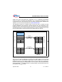
As in the ASC boot mode, the CAN BSL as the first task has to determine the CAN
baudrate at which the external host is communicating. This task requires the external
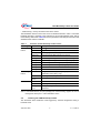
host to send initialization frames (see Table 2) continuously to the XC16x.
The identifier of the initialization frame has the baudrate detection pattern with value
555H. Data bytes 0 and 1 contain the information for the XC16x Bit Timing Register. This
provides the host the ability to change these protocol parameters to suit the individual
user application. The user must ensure that the correct value is sent, otherwise, the
communication could be halted. The XC16x will re-initialize its TwinCAN module to these
parameters and transmit the acknowledge frame with the identifier (data bytes 2 and 3)
sent from the host. Data bytes 4 and 5 tell the XC16x the number of messages to receive.
Since bytes 4 and 5 are defined by the host, the host has the ability to decide how large
a program to load.
Note: The bootstrap loader assumes all message data is valid and stores the received
data in PSRAM sequentially. The host should send its code/data sequentially in
multiples of 8 code/data bytes.
The CAN BSL starts measuring signal pulses at the TwinCAN receiver input pin RxDCA
(capturing the time between any edge). After pulse measurements the CAN BSL will
analyze the data to determine the smallest pulses. This time period is assumed to be one
CAN bit time and is used as the measured value for the initial setting for detecting the
correct baud rate.
Once the bit time has been determined, a software algorithm starts to determine the host
baudrate. The baud rate is determined by performing an iterative loop using the
parameters in Table 5. A detailed description for the calculation of the CAN bit time and
parameter search operations is provided in Chapter 2.7. If an exact match between the
calculated timer value and the measured timer value is found, then the loop will exit with
the current parameters. However, if an exact match is not found, then a search is made
to select the closest calculated value to the measured value.
Application Note
6
V 1.1, 2009-01