1
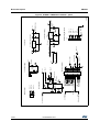
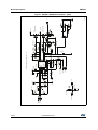
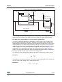
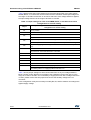
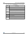
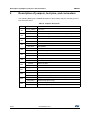
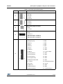
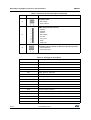
Contents
UM1823
Contents
1
2
3
System introduction . . . . . . . . . . . . . . . . . . . . . . . . . . . . . . . . . . . . . . . . . 6
1.1
Main characteristics . . . . . . . . . . . . . . . . . . . . . . . . . . . . . . . . . . . . . . . . . . 6
1.2
Target applications . . . . . . . . . . . . . . . . . . . . . . . . . . . . . . . . . . . . . . . . . . . 6
1.3
Safety and operating instructions . . . . . . . . . . . . . . . . . . . . . . . . . . . . . . . . 7
1.3.1
General terms . . . . . . . . . . . . . . . . . . . . . . . . . . . . . . . . . . . . . . . . . . . . . 7
1.3.2
evaluation board intended use . . . . . . . . . . . . . . . . . . . . . . . . . . . . . . . . . 7
1.3.3
evaluation board installation . . . . . . . . . . . . . . . . . . . . . . . . . . . . . . . . . . 7
1.3.4
Electrical connections . . . . . . . . . . . . . . . . . . . . . . . . . . . . . . . . . . . . . . . 8
1.3.5
evaluation board operation . . . . . . . . . . . . . . . . . . . . . . . . . . . . . . . . . . . 8
Board description . . . . . . . . . . . . . . . . . . . . . . . . . . . . . . . . . . . . . . . . . . . 9
2.1
System architecture . . . . . . . . . . . . . . . . . . . . . . . . . . . . . . . . . . . . . . . . . . 9
2.2
The board schematic . . . . . . . . . . . . . . . . . . . . . . . . . . . . . . . . . . . . . . . . 10
2.3
Circuit description . . . . . . . . . . . . . . . . . . . . . . . . . . . . . . . . . . . . . . . . . . . 16
2.3.1
Power supply . . . . . . . . . . . . . . . . . . . . . . . . . . . . . . . . . . . . . . . . . . . . . 16
2.3.2
Inrush limitation . . . . . . . . . . . . . . . . . . . . . . . . . . . . . . . . . . . . . . . . . . . 17
2.3.3
Brake function . . . . . . . . . . . . . . . . . . . . . . . . . . . . . . . . . . . . . . . . . . . . 17
2.3.4
Gate driving circuit . . . . . . . . . . . . . . . . . . . . . . . . . . . . . . . . . . . . . . . . . 18
2.3.5
Overcurrent protection . . . . . . . . . . . . . . . . . . . . . . . . . . . . . . . . . . . . . . 18
2.3.6
Current sensing amplifying network . . . . . . . . . . . . . . . . . . . . . . . . . . . . 19
2.3.7
The tachometer and Hall/encoder inputs . . . . . . . . . . . . . . . . . . . . . . . . 23
2.3.8
Temperature feedback and overtemperature protection . . . . . . . . . . . . 23
Hardware setting of the STEVAL-IHM023V3 . . . . . . . . . . . . . . . . . . . . . 24
3.1
Hardware settings for six-step (block commutation) control of
BLDC motors . . . . . . . . . . . . . . . . . . . . . . . . . . . . . . . . . . . . . . . . . . . . . . 24
3.2
Hardware settings for “Field Oriented Control” (FOC) in single-shunt
topology current reading configuration . . . . . . . . . . . . . . . . . . . . . . . . . . . 26
3.3
Hardware settings for FOC in three-shunt configuration . . . . . . . . . . . . . 27
4
Description of jumpers, test pins, and connectors . . . . . . . . . . . . . . . 30
5
Connector placement . . . . . . . . . . . . . . . . . . . . . . . . . . . . . . . . . . . . . . . 33
2/49
DocID026975 Rev 1