1
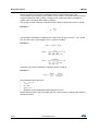
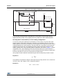
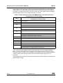
Board description UM1823 values, must be converted to be compatible with the single positive input of the microcontroller A/D converter used to read the current value. This means that the op amp must be polarized in order to obtain a voltage on the output that makes it possible to measure the symmetrical alternating input signal. The op amp is used in follower mode with the gain of the op amp set by resistor r and R: Equation 2 R+r G = -----------r It is possible to calculate the voltage on the output of the op amp, OP OUT - VOUT, as the sum of a bias, VBIAS, and a signal, VSIGN, component equal to: Equation 3 V OUT = V SIGN + VBIAS 3.3 V BIAS = --------------------------------------------------------- × G 1 1 1 -------- + -------- + ------ R1 R2 R3- × R3 I × R SHUNT V SIGN = --------------------------------------------------------- × G 1 1 1 ------- + -------- × R1 R1- + ------R2 R3 Total gain of the circuit including the resistors’ divider is equal to: Equation 4 V SIGN V SIGN G TOT = ---------------- = ---------------------------V IN R SHUNT × I with the default values this gives: • VBIAS = 1.7 V • G = 4.3 • GTOT = 1.7 • Maximum current amplifiable without distortion is 6.5 A. Please observe that the user can modify the max. current value by changing the values of the shunt resistors. 20/49 DocID026975 Rev 1