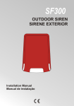
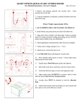
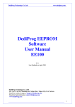
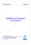
1
D
Deeddiipprroogg TTeecchhnnoollooggyy C
Coo.. LLttdd
w
ww
ww
w..ddeeddiipprroogg..ccoom
m
4F., No.7, Ln. 143, Xinming Rd., Neihu Dist., Taipei City 114, Taiwan
SF100, SF200, SF300
Serial Flash Programming solutions
The Innovative solution to update the Serial Flash on board and Offline
•
High performances for low price
•
USB full speed support
•
ICP connector to work with Serial Flash soldered on board
(SF100 and SF300)
•
Stand Alone mode (SF300): Update the Serial flash without computer
•
DIP socket to connect the DediProg adapters according to the Serial Flash
package (SF200 and SF300)
•
Friendly and powerful tool with free life time update via Website
•
Portable programmer :
SF100 and SF200 : (10cm X 5cm X 2 cm)
SF300 (9.8cm x 9.1cm x 2.2cm)
•
Advanced I/O control (SF100 and SF300)
DediProg
Page 1/17
May 10
D
Deeddiipprroogg TTeecchhnnoollooggyy C
Coo.. LLttdd
w
ww
ww
w..ddeeddiipprroogg..ccoom
m
Table of content:
I. Product Overview ............................................................... 3 II. Product Description ................................................ 4 A. B. C. SF100 .....................................................................................4 SF200 .....................................................................................6 SF300 .....................................................................................7 III. Products Features ................................................... 8 A. B. C. USB mode ..............................................................................8 Window DOS command mode (SF300) ................................8 Standalone mode (SF300) ......................................................9 1. 2. 3. 4. Project Preparation ................................................................................. 9 Mode switch ........................................................................................... 9 Standalone programming ..................................................................... 10 SF300 description ................................................................................ 10 IV. Specification .......................................................... 11 A. B. USB Connector ....................................................................11 DC and IO characteristics ....................................................11 1. 2. 3. 4. V. A. B. A. Socket DC Characteristics (SF200, SF300) ......................................... 11 ICP DC and AC characteristics (SF100, SF300) ................................. 11 ICP timing (SF100, SF300) ................................................................. 15 Host PC requirements .......................................................................... 16 Programming Performance ................................. 16 USB Mode ............................................................................16 Standalone Mode (SF300 only) ...........................................16 Revision history ...................................................................17 Important notice:
This document is provided as a guide line and must not be disclosed without consent
of DediProg. However, no responsibility is assumed for errors that might appear.
DediProg reserves the right to make any changes to the product and/or the
specification at any time without notice. No part of this document may be copied or
reproduced in any form or by any means without prior written consent of DediProg.
DediProg
Page 2/17
May 10
D
Deeddiipprroogg TTeecchhnnoollooggyy C
Coo.. LLttdd
w
ww
ww
w..ddeeddiipprroogg..ccoom
m
I. Product Overview
The Universal Programmers available on the market are not optimised for the Serial
Flash offering low performances for high price.
Our DediProg team has then developed for you, a complete portfolio of solutions to
cover all your needs and for your entire satisfaction.
A SF100
In Circuit Programming solution to program
the Serial Flash soldered on application
board
B SF200
Engineering solution to program the Serial
Flash on the socket
C SF300
All-in-one serial flash programmer: incircuit-programming, offline programming
and standalone programming
With their associated sockets:
TSSOP8 - SO8N - SO8W - SO16W - MLP6*5 - MLP8*6 - Test Clip
DediProg
Page 3/17
May 10
D
Deeddiipprroogg TTeecchhnnoollooggyy C
Coo.. LLttdd
II.
w
ww
ww
w..ddeeddiipprroogg..ccoom
m
Product Description
A.SF100
The SF100 programmers are used to read, program or update the Serial Flash
soldered on board or inserted in the socket of the Dediprog Backup Boot Flash
tool by using the computer software through USB communication.
The SF100 is composed of the main following parts:
-
USB male Connector: To connect the programmer to the computer.
A USB cable extension is provided for more flexibility and
convenience.
-
An ICP Connector: to connect the SPI signals and power supply to
the application Serial Flash via a flat cable. The flat cable is flexible
and convenient to manipulate, and can be changed easily before
connection. For customization of the ICP-cable (number of signals, pin
out assignment or connector size), please contact Dediprog.
-
LED: to indicate the status of the operation in progress.
-
Start button: to start operations from the programmer
Fig 1: SF100 Programmer
Operation LED
USB
ISP pin
header
Start Button
DediProg
Page 4/17
May 10
D
Deeddiipprroogg TTeecchhnnoollooggyy C
Coo.. LLttdd
w
ww
ww
w..ddeeddiipprroogg..ccoom
m
The SF100 programmer has been designed to meet the strong and growing demand of
serial flash users to program and update the memories soldered on board during
development, production, field manipulation or repairing with high performance and
low cost. Before trying to update the Serial Flash on Board, be sure that the SPI
controller and the application are compatible with the In Circuit Programming method
to avoid any conflict with the programmer.
DediProg has published Application Note to help designers to implement the ICP
method and will be pleased to answer to any of your questions on this subject.
Fig 2: SF100 connected to the application pin header
The software provided with the SF100 has been developed to offer a complete
portfolio of features with a friendly and simple interface to not require any technical
expertise.
SF100 can also be used together with Dediprog backup boot flash modules so that it
forces the application to boot from the backup flash located in the backup boot flash
module instead of the soldered SPI flash on the application.
The backup serial flash can then be accessed at any time with the SF100 without any
possible conflict with the application controller.
Fig 3: Backup Boot Flash (BBF) connected to SF100
DediProg
Page 5/17
May 10
D
Deeddiipprroogg TTeecchhnnoollooggyy C
Coo.. LLttdd
w
ww
ww
w..ddeeddiipprroogg..ccoom
m
B.SF200
SF200 Engineering programmer has been optimized to offer the highest Serial flash
performance for the market lowest price. These dedicated programmers will be
helpful, powerful and convenient for your development, production, failure analysis
or field update.
The software provided with the SF200 has been developed to offer a complete
portfolio of features with a friendly and simple interface to not require any technical
expertise.
Fig 4: SF200
Socket adaptor
Operation LED
Start Button
USB
DediProg
Page 6/17
May 10
D
Deeddiipprroogg TTeecchhnnoollooggyy C
Coo.. LLttdd
w
ww
ww
w..ddeeddiipprroogg..ccoom
m
C.SF300
SF300 comes with all the capability provided by SF100 and SF200. In addition, it
further allows standalone programming without the need of a PC. Contents and
programming procedures are prepared in the SF300 through the software. LCD
display, LED, start button, buzzer, reset counter button are equipped to ensure good
user friendliness during the standalone programming.
Fig 5: SF300
Reset Counter Button
LCD Display
USB
Button Switch
Start Button
LED
ICP Connector
DIP Socket
The SF300 has been designed for small volume production. For high volume
production please refer to our Serial Flash dedicated Gang programmer Race100
family.
DediProg
Page 7/17
May 10
D
Deeddiipprroogg TTeecchhnnoollooggyy C
Coo.. LLttdd
III.
w
ww
ww
w..ddeeddiipprroogg..ccoom
m
Products Features
A.USB mode
In USB mode, user can control the programmer operations via a friendly interface.
He can load a file, blank check, program and verify the target Serial Flash. Batch
button provides an easy way to perform more than one operations in one click.
User can also edit the buffer, files and SPI Flash content and compare.
Fig 6: USB Window interface
To get more information on the software features, please refer to our user manual.
B. Window DOS command mode (SF300)
User can quickly perform some repetitive operations just by typing the command on
our Window DOS interface or control programmer using another software (compiler
or ICT tester).
Fig 7: Window DOS interface
DediProg
Page 8/17
May 10
D
Deeddiipprroogg TTeecchhnnoollooggyy C
Coo.. LLttdd
w
ww
ww
w..ddeeddiipprroogg..ccoom
m
C.Standalone mode (SF300)
Standalone mode procedures:
1. Project preparation,
2. Mode switch,
3. Standalone programming
1. Project Preparation
In order to perform stand alone programming, the contents and the programming
operation procedures have to be pre-downloaded to the SF300 through the USB with
the software provided by Dediprog. SF300 has embedded a 128Mb SPI Flash and
therefore it is capable of supporting standalone programming for all serial flash equal
and under 128Mb.
Prepare a standalone programming project
1. connect the SF300 to a PC with SF software installed and make sure the
programmer is switched to USB mode
2. open the SF software and click on the “update standalone project” tab
Fig 8: SF300 software interface
3. Load the file
4. click on “Config” to select the target chip type and the standalone operation
procedures
5. click on “Update” to download the project information to the SF300
2. Mode switch
SF300 provides 2 operation modes through a switch.
- USB mode: to control the programming via the computer tool
- Stand Alone mode: to work independently from computer
DediProg
Page 9/17
May 10
D
Deeddiipprroogg TTeecchhnnoollooggyy C
Coo.. LLttdd
w
ww
ww
w..ddeeddiipprroogg..ccoom
m
3. Standalone programming
When the project is prepared in the SF300 internal SPI Flash and the mode is
switched to SA mode, the user can start the standalone programming by the
following steps.
1. insert the chip into the socket
2. press the start button
3. wait for green LED ON and remove the chip from the socket
4. SF300 description
a)
LCD Display
LCD displays the standalone project related information such as the file checksum,
chip type, pass counter, and fail counter.
b)
Start button
By pressing the start button, the SF300 starts to execute the operation procedures
defined in the project pre-downloaded to the SF300.
c)
Reset counter button
The reset button is used to reset the counter information.
d)
USB Connector
USB connector is used to communicate with the SF software during the USB mode or
to provide the power during the standalone mode.
e)
DIP Socket
DIP socket is used to connect to different socket adaptors provided by Dediprog in
order to support all SPI flash packages.
f)
LED Display
Red Led: error
Orange Led: operation on going
Green Led: pass
DediProg
Page 10/17
May 10
D
Deeddiipprroogg TTeecchhnnoollooggyy C
Coo.. LLttdd
IV.
w
ww
ww
w..ddeeddiipprroogg..ccoom
m
Specification
A.USB Connector
The USB connector type A is available to communicate with the computer tool
or to supply the programmer in Stand Alone mode (SF300 only).
When in Stand Alone mode, the SF300 has to be supplied through the USB
connector or the 9V power jack. This could be achieved by:
- Connecting the SF300 to a computer for the USB power
- Connecting the SF300 to a standard USB Hub (500mA min)
- Connecting the SF300 to the 9V power adaptor through the power jack
USB Power supply specification:
Vdd = 5V ± 5%
Idd min = 500mA
B. DC and IO characteristics
1. Socket DC Characteristics (SF200, SF300)
SPI Flash can be supplied with:
- All SF200 and SF300 versions: 3.3V
- SF200 firmware Version 3.xx and later and all SF300 version: 2.5V,
1.8V
User can select the Vcc on the software interface.
The SPI signals are generated according to the Vcc selected.
2. ICP DC and AC characteristics (SF100, SF300)
The ICP connector is a 7x2 pin header straight type with 2.54mm pitch. It is used to
control the application SPI Flash, and if necessary supply the SPI Flash, provide the
high voltage to the SPI Flash, or reset the application chipset, etc.
Table 1: ICP connector pin out
1
I/O1
3 I/O2 or CS2
5
Vcc
7
CS
9
MISO
11
Vpp/Acc
13
SCL
DediProg
I/O4
NC
GND
CLK
MOSI
I/O3
SDA
Page 11/17
2
4
6
8
10
12
14
May 10
D
Deeddiipprroogg TTeecchhnnoollooggyy C
Coo.. LLttdd
w
ww
ww
w..ddeeddiipprroogg..ccoom
m
Table 2: Description of the signals:
Pin
Name of
Description
Number the
signals
1,2,3,12 General
General I/O are used to control optional pins of the SPI
I/O
Flash (hold, WP) or switch the application to a specific
mode (reset chipset or switch OFF MOSFET)
3
I/O2
I/O2 can also been used as a second Chip Select (CS2) to
update two serial Flashes on the board (option selected
from the DediProg software). *
4
NC
Not Connected
5
Vcc
Vcc is used to supply the application SPI Flash
6
GND
GND is the common ground shared between application
and programmer
7
CS
SPI chip select of the application SPI Flash
8
CLK
SPI clock signal for the application SPI Flash
9
MISO
Data out from the application memory (master in slave out)
10
MOSI
Data in of the application SPI Flash (master out slave in)
11
Vpp
High voltage applied on the SPI Flash to speed up the
programming and erasing operations
13,14
SCL, SDA I2C bus reserved for future use
* available on the products with firmware 2.x.x and after
The application connector pin count can be optimized to the application needs and
reduced down to a minimum of 5 pins only for the SPI communication and mistake
proof pin (CS, CLK, MISO, MOSI, and GND).
For explanation on how to design your application and use the programmer in the
different scenario, please review the document available on Dediprog website under
“Documentation” section or contact Dediprog directly.
a) Application SPI Flash supply: Vcc
Specification for the ICP Vcc pin:
- Vcc is set at 3.3V by default and can be switched to 2.5V or 1.8V on
the hardware version 3 and after (hardware version can be identified
with the firmware version V3.xx)
- Icc max supplied = 50mA
The application SPI Flash can be supplied by two different sources:
1) by the programmer via ICP Vcc pin at 3.3V
2) by the application according to the SPI Flash specification
b) SPI signals management: CS, CLK, MISO, and MOSI
The SPI signals are sued to communicate with the application SPI Flash with a high
frequency (24MHZ or 12MHz according to the firmware). The frequency can be also
adjusted on the latest hardware. The signals are CMOS compatible and are switched
in High Impedance when not used.
DediProg
Page 12/17
May 10
D
Deeddiipprroogg TTeecchhnnoollooggyy C
Coo.. LLttdd
w
ww
ww
w..ddeeddiipprroogg..ccoom
m
Table 3: DC specification for SPI signals and IO
Symbol Parameter
Test condition
Vcc(V)
Io(mA)
2.7V to 3.6V
High Level
Vih
2.3V to 2.7V
Input Voltage
1.65V to 1.95V
2.7V to 3.6V
Low Level
Vil
2.3V to 2.7V
Input Voltage
1.65V to 1.95V
3V
-24mA
Ioh
Iol
High Level
Output current
Low Level
Output current
Value
Unit
2V
1.7V
0.65XVcc
0.8V
0.7V
0.35XVcc
V min
V min
V min
V max
mA
2.7V
-12mA
mA
2.3V
-12mA
mA
1.65V
-4mA
mA
3V
24mA
mA
2.7V
12mA
mA
2.3V
12mA
mA
1.65V
4mA
mA
Cap
Capacitance
10nF
This specification is relative to individual capability of one signal.
nF typ
ESD high performance protection compliant with IEC61000-4-2 level 4:
15kV (air discharge)
8kV (contact discharge)
Remark: the total capacitance added on the application SPI bus will also depend on
the ICP cable length. The ICP cable length must be reduced at the minimum. The SPI
flash output buffer capability (MISO) is limited compared to the programmer
performances. So even if the programmer is able to drive high capacitance, the Serial
Flash soldered on the application will probably not (information read from SPI Flash
will be wrong).
d) Smart management of the SPI Flash Vcc and SPI signals
In order to minimize the impact of the ICP method on the chipset and application
board, the programmer supplies the application Serial Flash with Vcc and SPI signals
only during the programmer and Serial Flash operations.
Advantages:
- The programmer is plugged on the application board with Vcc OFF and SPI signals
in High Impedance to avoid inrush current.
- All the ICP pins are protected with ESD high performance protections to discharge
the Electronics charge before the connection and protect the application.
- The Serial Flash Vcc and SPI signals are provided only when the user send the
command and are switched OFF automatically when the operation is completed.
DediProg
Page 13/17
May 10
D
Deeddiipprroogg TTeecchhnnoollooggyy C
Coo.. LLttdd
w
ww
ww
w..ddeeddiipprroogg..ccoom
m
Therefore, the programmer is transparent for the application and can be kept
connected during application trials.
e) High voltage supply: Vpp/Acc
(applicable to products with 3.x.x firmware)
Specification for the Vpp pin
Vpp = 8.5V to 12.5V
Ipp max = 50mA
The Vpp high voltage can be supplied by the programmer and sued to speed up
programming and erasing of the application Serial Flash if this feature is supported by
the Serial Flash supplier.
The Vpp supply will be applied automatically by the programmer on the Vpp pin only
during erase, write, or programming operations and only if the Vpp option has been
enabled on the computer tool. The programmer will also control the Vpp voltage level
according to the Serial Flash connected and its specification.
f) I/O management: I/O1, I/O2, I/O3, I/O4
Four general outputs are available on the ICP connector for custom needs. The IOs
are in HZ state if there is no software operation ongoing even if the power is
connected. The IOs are driven high or low when the software is running command.
I/O4, IO2 = driven High
I/O1, I/O3 = driven Low
These outputs can be useful to drive Wp, Hold, reset the application chipset, or switch
Off the MOSFET transistors in the application board. They are CMOS compatible
and are switched in High Impedance when the software is not executing commands.
The I/O2 can also be used as a second Chip Select to update a second SPI Flash
soldered on the board. In this case, I/O2 have to be connected to the application CS2
and the option “Chip 2” has to be selected in the DediProg software.
For the DC characteristics, please refer to table 3.
ESD high performance protection compliant with IEC61000-4-2 level 4:
15kV (air discharge)
8kV( contact discharge)
DediProg
Page 14/17
May 10
D
Deeddiipprroogg TTeecchhnnoollooggyy C
Coo.. LLttdd
w
ww
ww
w..ddeeddiipprroogg..ccoom
m
3. ICP timing (SF100, SF300)
The IO has been designed to set the application in external programming mode before
applying the SPI signal. They can be used to reset the chipset and application, to drive
multiplexers and switch SPI bus from application controller to programmer, to turn
OFF MOSFET and isolate the SPI bus when programmer is working.
This is the behavior of the IO and SPI signals on our last firmware V3.0.2
1) If No programmer operation is on going
All our SF100 outputs are equivalent to high impedance.
2) When an operation is requested on the user interface
- IO1, IO2, IO3 and IO4 are first switched in Low impedance
- IO1 and IO3 are driven low
- IO2 and IO4 are driven high
4) 3ms after IO are switched to Low Impedance, the CS, Clock and MOSI outputs
are switched in low impedance too.
- CS is driven high
- Clock and MOSI are driven low.
5) The programmer is then ready for the communication with the Serial Flash.
So designer can use IO3 to reset or switch the application in external programming
mode. Application will have a delay of 3ms between IO3 is driven low and
Programmer SPI outputs are switched from High Impedance to Low Impedance.
SPI communication starts 6ms after IO3 has been driven low.
Fig 9: IO and SPI timing
DediProg
Page 15/17
May 10
D
Deeddiipprroogg TTeecchhnnoollooggyy C
Coo.. LLttdd
w
ww
ww
w..ddeeddiipprroogg..ccoom
m
4. Host PC requirements
The SF100, SF200 and SF300 interface with IBM compatible PC's through the USB
2.0/1.1 port. This gives full compatibility with the latest PC's, notebooks and
portables.
System Requirements:
¾ PC with Windows XP / Vista / Win7
¾ Hard disk with at least 64 MB free space.
System Interface:
¾ PC connexion ………....................……......…...........……....USB 2.0/1.1 port
V. Programming Performance
A.USB Mode
Table 4: Programming and verify in USB mode
SPI Flash
8Mb
16Mb
32Mb
Densities
USB
8s
14s
64Mb
128Mb
70s
108s
37s
Note 1: The measurements are done with SF100, or SF200, or SF300 with firmware
2.0.5 and software version of 2.0.37. The tested memories are from a single serial
flash manufacturer.
Note 2: new hardware versions with firmware 3.x.x allow Vpp/Acc high speed
programming if the chip supports it. The programming performance will be better if
applying Vpp/Acc during the programming or erasing for chips supporting such
feature.
B.Standalone Mode (SF300 only)
Table 5: Programming and verify in Stand Alone mode
SPI Flash
Densities
8Mb
16Mb
32Mb
64Mb
128Mb
Stand Alone
without Vpp
8s
14s
32s
64s
84s
Stand Alone
with Vpp
8s
13s
24s
35s
64s
DediProg
Page 16/17
May 10
D
Deeddiipprroogg TTeecchhnnoollooggyy C
Coo.. LLttdd
w
ww
ww
w..ddeeddiipprroogg..ccoom
m
A.Revision history
Date
Version
Changes
17/05/10
May 10
SF100 and SF200 updated with 3 LED and Start button. System
requirements updated
DediProg Technology Co. Ltd
4F., No.7, Ln. 143, Xinming Rd., Neihu Dist., Taipei City 114,
Taiwan
Email for technical support: [email protected]
Email for Sale information: [email protected]
www.DediProg.com
Information furnished is believed to be accurate and reliable. However, DediProg
assumes no responsibility for the consequences of use of such information nor for any
infringement of patents or other rights of third parties which may result from its use.
Specifications mentioned in this publication are subject to change without notice.
This publication supersedes and replaces all information previously supplied.
All rights reserved
Printed in Taiwan.
DediProg
Page 17/17
May 10