1
Chapter 5: Subsystem Maintenance
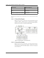
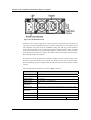
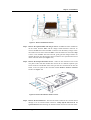
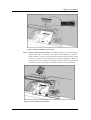
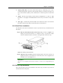
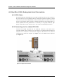
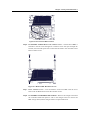
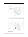
Figure 5-2: Disconnect the BBU Connector
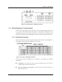
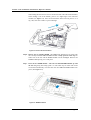
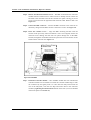
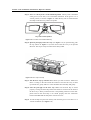
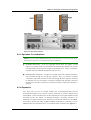
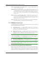
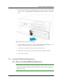
Step 6. IF THE BBU FAILED Remove the retention screws – The bracket of BBU is
attached to the IO board through two retention screws that pass through the
bracket, IO board and spacers that connect the IO board to the controller board.
Remove these screws.
Figure 5-3: Remove BBU Retention Screws
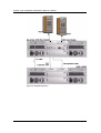
Step 7. Insert retention screws – Line the brackets of the new BBU with the screw
holes in the IO Board and re-insert the retention screws.
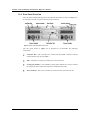
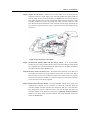
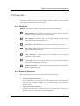
Step 8. IF THE BBU CHARGER BOARD FAILED – Remove the charger board from
the controller board and replace it with a new charger board. To remove the
BBU charger board, lift the charger board in an upward direction.
Controller Module Maintenance
5-7