1
SMV 3000 Transmitter
Electronics Module Replacement
Step
10
Action
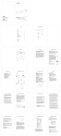
Align PWA connector on Temperature PWA over the connector on Main PWA and slide
connector pins through Temperature PWA connector. See figure. Replace two retaining
screws and secure Temperature and Main PWA to bracket (located on underside of Main
PWA).
Main PWA
Flex Tape
Connector
Power
Connector
Retaining
Clip
PWA
Connector
Temperature PWA
Temperature
Input
Connector
PWA
Connector
Screw
Screw
11
Replace plastic bracket and retaining clip over ends of Main PWA and Temperature PWA.
Note that the end of Temperature PWA engages slot in bracket. Secure with a screw.
12
Carefully insert electronics module back into transmiter housing. Secure to housing with the
two captive mounting screws on topside of electronics module.
13
Refer to figure in step 10 and Figure 1.
•
Reconnect temperature input connector to Temperature PWA on underside of module.
•
Reconnect flex-tape connector and power connector to Main PWA.
•
Secure metal retaining clip on underside of electronics module.
ATTENTION
Once the Electronics module has been replaced, the transmitter will require a bench
calibration using precision ABSOLUTE pressure equipment and/or precision DRAFT pressure
equipment, depending upon the transmitter model. Refer to the SMV 3000 User’s Manual for
the correct procedure.
NOTE: You may need to download a valid configuration to the transmitter before beginning
the calibration.
Procedure continued on next page ⇒
Page 6 of 7
Form 34-SM-33-01