1
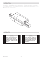
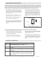
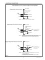
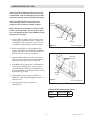
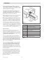
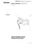
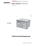
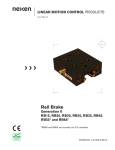
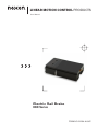
LINEAR MOTION CONTROL PRODUCTS
User Manual
Electric Rail Brake
RBE Series
FORM NO. 21254-A-0307
In accordance with Nexen’s established policy of constant product improvement, the specifications contained in this
manual are subject to change without notice. Technical data listed in this manual are based on the latest information
available at the time of printing and are also subject to change without notice.
Technical Support: 800-843-7445
(651) 484-5900
www.nexengroup.com
DANGER
Read this manual carefully before installation and operation.
Follow Nexen’s instructions and integrate this unit into your system with care.
This unit should be installed, operated and maintained by qualified personnel ONLY.
Improper installation can damage your system or cause injury or death.
Comply with all applicable codes.
Nexen Group, Inc.
560 Oak Grove Parkway
Vadnais Heights, Minnesota 55127
ISO 9001 Certified
Copyright 2007 Nexen Group, Inc.
FORM NO. 21254-A-0307
Table of Contents
Installation -----------------------------------------------------------------------------------------------------------------------------4
Wiring Installation Guidelines ---------------------------------------------------------------------------------------------5
Electrical Connections ------------------------------------------------------------------------------------------------------5
Engaged Output Signal Connection Diagrams---------------------------------------------------------------------6
Mounting RBE on a Rail-----------------------------------------------------------------------------------------------------7
Operation ------------------------------------------------------------------------------------------------------------------------------8
Friction Shoe Service -------------------------------------------------------------------------------------------------------------9
Warranty -----------------------------------------------------------------------------------------------------------------------------10
FORM NO. 21254-A-0307
INTRODUCTION
The Nexen Electric Rail Brake (RBE) is for use on profile guide rails. This brake features 24 VDC operation, ease of
control, engagement feedback, and visual indication of brake status. Indicators on the RBE inform the user of rail engagement and fault or service indications.
INSTALLATION
CAUTION
CAUTION
Mount in a shock and vibration free
area with an ambient temperature
greater then 0°C [32°F] and less than
60°C [140°F]. The RBE is for indoor
use only.
Dynamic applications, including emergency stops, are not recommended
with the Nexen RBE. Minimize linear
travel of RBE when engaging and
disengaging.
FORM NO. 21254-A-0307
Wiring installation guidelines
This product is designed to minimize the effects of ElectroMagnetic Interference (EMI) on its operation, but as
with any electronic device, proper installation and wiring methods are necessary to ensure proper operation. By
doing so, the interference from external effects such as electrical line spikes, electrical noise, static electricity, etc.
will be minimized. The following methods outline wiring installation guidelines to protect your system:
•
All input and output signal and sensor cables must
be shielded with the shields tied to earth ground at
one end. In case of very high frequency (MHz range)
electrical noise, both ends of the shield need to be
tied to earth ground.
•
Keep cable length and unshielded leads as short as
possible. Think of them as antennae for noise.
•
Use power line filters to suppress interference on
the AC voltage lines that power the unit.
•
•
Isolate signal and sensor cables from cables carrying AC voltages, power for high current loads
or relays and solenoids. Either relocate the signal
and sensor cables away from other cables or use
grounded metal conduits to shield them. This will
reduce the potential for noise interference between
the signal and sensor cables and the other noisy
cables.
Relay
R
Place a resistor-capacitor network (snubber) across
inductive coils such as relays and solenoids in order
to stop electrical interference at the source (See
Figure 2).
Snubber
C
Figure 2
Snubber applied across relay coil
For environments that experience high levels of static electricity follow these additional guidelines:
•
Remove the static charge from material carrying it.
In the case of webs that carry static charges, there
are static charge removal products available such as
static bars and ionized blowers.
•
Ensure that sensors and machine frames are
grounded to earth through a low impedance path.
•
Wrap grounding tinsel around sensors and cables
that are close to the source of the static electricity
and ground the tinsel to earth.
•
Tie all signal and sensor cable shields directly to
earth ground without passing through the electronic
device. This will help prevent high voltage interference from coupling into other circuits within the
device.
Electrical Connections
Cable Wires
Function
Brown
+24 VDC & Common: RBE requires 24VDC to operate
(Refer to SPECIFICATIONS for current rating).
Blue
DC Common
White
Engagement Input Signal: Applying 24 VDC to this input will cause RBE
to disengage from rail. Removing all voltage from this input will cause RBE to engage rail.
Black
RBE Engaged Output Signal: This is an open collector transistor output
(Refer to SPECIFICATIONS for ratings) that signals when RBE engages
the rail. Transistor is switched on while RBE is engaged and is off while
RBE is disengaged.
Table 1
FORM NO. 21254-A-0307
ELECTRICAL CONNECTIONS
RBE ENGAGED OUTPUT SIGNAL CONNECTION DIAGRAMS
User Supplied
Engaged Output Tied to PLC Input
VD C (See Specifications for
maximum voltage.)
R (See Note.)
RBE
Black
To PLC Input
Blue
VD C Common
User Supplied
NOTE:
The minimum value of resistor (R) is 10 x VDC.
User Supplied
Engaged Output Tied to External Indicator
External Indicator
(See Note)
RBE
R
Black
VD C (See Specifications for
maximum voltage and
current ratings.)
Blue
VD C Common
User Supplied
NOTE:
The minimum value of Resistor (R) is equal to VDC divided by
the maximum current limit of the indicator. Be sure current requirement
of External Indicator does not exceed capability of RBE output.
User Supplied
Engaged Output Tied to External Inductive Coil
(See Notes)
External
Coil
RBE
Black
VD C (See Specifications for
1N00
Blue
maximum voltage and
current ratings.)
VD C Common
User Supplied
Figure 3
NOTES: 1. Be sure current requirement of External Coil does not exceed
capability of RBE output.
. Any inductive load, such as a relay coil, must have a 1N00,
or equivalent, diode across it as shown.
FORM NO. 21254-A-0307
Mounting RBE on A RAIL
NOTE: The RBE Rail Brake friction shoe gap is set
at the factory to accommodate specific rails and is
not adjustable. Visit www.nexengroup.com for RBE
dimensional drawing showing mounting dimensions.
NOTE: The RBE Rail Brake does not have an
internal bearing system, so it must be used in
conjunction with at least two bearing carriages.
Bearing*
(2x min.)
NOTE: RBE must be protected from effects of Electrostatic Discharge (ESD). To ensure proper operation, a low impedance path from the RBE housing to
earth ground is required.
Rail Brake
1. Pull out RBE from shipping box and remove shoe
retaining foam from between shoes. Visually confirm that both shoes are present as shoes can fall
out if RBE is handled abruptly while unmounted.
Rail*
Bearing*
Figure 4
*Customer Supplied
2. Before locating RBE on a rail, provide 24 VDC
power to RBE (Refer to ELECTRICAL CONNECTIONS). Note that shoes move toward each other.
RBE will not fit on to rail in this condition.
Mounting
Fasteners*
3. Apply 24 VDC to White wire. Next, push shoes
back into housing with finger to ensure adequate
opening between them to accommodate rail.
4. Slide RBE onto rail and position it underneath the
mounting plate (See Figure 4). Using customer
supplied fasteners (See Figure 5 and Table 2), finger tight both RBE to mounting plate and mounting
plate to bearing carriages.
Mounting
Plate*
5. Engage RBE to rail by removing 24 VDC from
White wire. Note that RBE Engaged indicator is lit
(See Figure 6).
Figure 5
*Customer Supplied
6. After engagement, tighten all fasteners
(See Figure 5).
RBE Rail Brake Fastener Requirements
Model
Fastener Size
Qty.
RBE 25
M6 x 1.0
2
Table 2
FORM NO. 21254-A-0307
OPERATION
Power is required anytime the RBE is to change state
from engaged to disengaged, or, disengaged to engaged. Otherwise, power can be removed and the RBE
will remain engaged or disengaged.
Service Indicator
After applying power, RBE will look at Engagement
Input Signal. If the signal has 24 VDC applied to it,
then RBE will disengage from rail. Or if the signal has 0
VDC applied to it, then RBE will engage rail.
RBE Engaged Output Signal can be monitored for verification that RBE has engaged or disengaged rail.
After engaging rail, RBE Engaged Output Signal’s transistor will turn on, dropping this signal’s voltage to less
than one volt. In addition, the RBE Engaged Indicator
will illuminate for the entire time RBE has engaged rail.
RBE Engaged
Indicator
Figure 6
After disengaging rail, RBE Engaged Output Signal’s
transistor will turn off, causing this signal’s voltage to be
pulled up by the customer supplied pull up resistor and
source. In addition, the RBE Engaged Indicator will turn
off for the entire time RBE is disengaged from rail.
Blinks
Meaning
“none”
RBE operation is normal
1
Engagement timer expired
Service Indicator
2
Excessive motor current
A Service Indicator (See Figure 6) provides visual
indication for troubleshooting and service issues. This
indicator will blink if an engagement fault is encountered
or if RBE needs serviced. The number of blinks corresponds to the event (See Table 3).
3
Low motor torque
4
Shoes have backed away from rail
5
RBE did not clamp on rail
6
Thermal limit exceeded
7
Time to rotate shoes
In case of 1-6 blinks, RBE may not be clamped onto
rail and requires attention by the customer to resolve
any issues. Also, the RBE Engaged Output Signal will
go to a voltage high state and RBE Engaged Indicator
will turn off. These conditions are cleared automatically
after a successful engagement.
8
RBE requires servicing
Table 3
In case of 7 blinks, this indicates it is time to rotate the
shoes, refer to SERVICE INSTRUCTIONS section.
This indicator will continue to blink for 10,000 engagements and then automatically turn off. In case of an
engagement fault, the indicator will give priority to fault
indication and then revert back to service indication after
the fault is resolved.
In case of 8 blinks, this indicates the RBE’s service
life has been reached and RBE needs to replaced or
returned to Nexen Group, Inc for rebuilding. Once this
limit has been reached, then RBE Engaged Output
Signal will always be at a voltage high thus denying
engagement feedback.
FORM NO. 21254-A-0307
Friction Shoe sERVICE
NOTE: There are no serviceable parts, excluding shoe, within the RBE Rail Brake. Nexen recommends that
the RBE be returned to Nexen Group, Inc. for servicing. Do not attemp to remove or dismantle any part of
the RBE assembly. In the case of an RBE malfunction or service problem, contact Nexen Customer Service.
DANGER
RBE End Cap
Secure the load before disengaging the
RBE. Failure to support the load may result
in serious injury or death after the RBE
releases the rail.
V
Position Mark
V
Friction Shoe Service Procedure
1. Secure the load from moving and then remove RBE
mounting fasteners. The RBE is now free of the
mounting plate.
2. Apply 24 VDC to the White wire to disengage RBE
from rail.
3. Slide RBE off of rail.
4. Inspect the shoes for wear and damage. Normal witness marks will not exceed 0.03mm (.001 inch) in
depth where the shoes contact the rail. If the shoes
are worn beyond this point, or other damage exists,
contact Nexen.
5. Mark position of shoes (See Figure 7) with a permanent marker.
6. Remove shoes.
7. Clean and re-lubricate shoes with the following approved greases, being careful not to clean off mark
from step 4.
Friction Shoe
Rotate Shoe180
Mark in new
position
o
V
Figure 7
Approved Shoe Greases (customer supplied):
• Chevron SRI 2
• Exxon Polyrex
• Nippon Oil FNS
8 Rotate shoes 180 degrees from position in step 4.
9. Install shoes into RBE.
10. Clean lubricant from exposed surface of shoe.
11. Re-install RBE (Refer to RBE MOUNTING section).
Specifications
Power Supply
24 VDC +/- 5%
RBE25: 24 VDC @ 2.5 A peak
Cycle Rate
One engagement or
disengagement per second,
maximum
Ambient
Temperature
0o - 60o C
[32o - 140o F]
Rotate Shoes
Every 100,000
engagements
Engagement Input
0-5 VDC – engage
15-24 VDC – disengage
Service Life
225,000 engagements
RBE Engaged
Output
Open Collector NPN Transistor
I maximum = 100 mADC
VLOW = 1 V maximum@50 mA
VHIGH = 24 VDC maximum
Holding Force
1000 N [225 lbs] maximum
Response Time
.45 seconds minimum to engage
.15 seconds minimum to disengage
Backlash at Rated Holding
Force
0.30mm [.012 in]
FORM NO. 21254-A-0307
Table 4
WARRANTY
Warranties
Nexen warrants that the Products will be free from any defects in material or workmanship for a period of 12 months
from the date of shipment. NEXEN MAKES NO OTHER WARRANTY, EXPRESS OR IMPLIED, AND ALL IMPLIED
WARRANTIES, INCLUDING WITHOUT LIMITATION, IMPLIED WARRANTIES OF MERCHANTABILITY AND FITNESS FOR A PARTICULAR PURPOSE ARE HEREBY DISCLAIMED. This warranty applies only if (a) the
Product has been installed, used and maintained in accordance with any applicable Nexen installation or maintenance
manual for the Product; (b) the alleged defect is not attributable to normal wear and tear; (c) the Product has not been
altered, misused or used for purposes other than those for which it was intended; and (d) Buyer has given written notice of the alleged defect to Nexen, and delivered the allegedly defective Product to Nexen, within one year of the date
of shipment.
Exclusive Remedy
The exclusive remedy of the Buyer for any breach of the warranties set out above will be, at the sole discretion of Nexen, a repair or replacement with new, serviceably used or reconditioned Product, or issuance of credit in the amount of
the purchase price paid to Nexen by the Buyer for the Products.
Limitation of Nexen’s Liability
TO THE EXTENT PERMITTED BY LAW NEXEN SHALL HAVE NO LIABILITY TO BUYER OR ANY OTHER PERSON FOR INCIDENTAL DAMAGES, SPECIAL DAMAGES, CONSEQUENTIAL DAMAGES OR OTHER DAMAGES OF ANY KIND OR NATURE WHATSOEVER, WHETHER ARISING OUT OF BREACH OF WARRANTY OR
OTHER
BREACH OF CONTRACT, NEGLIGENCE OR OTHER TORT, OR OTHERWISE, EVEN IF NEXEN SHALL HAVE
BEEN ADVISED OF THE POSSIBILITY OR LIKELIHOOD OF SUCH POTENTIAL LOSS OR DAMAGE. For all of
the purposes hereof, the term “consequential damages” shall include lost profits, penalties, delay images, liquidated
damages or other damages and liabilities which Buyer shall be obligated to pay or which Buyer may incur based
upon, related to or arising out of its contracts with its customers or other third parties. In no event shall Nexen be liable for any amount of damages in excess of amounts paid by Buyer for Products or services as to which a breach of
contract has been determined to exist. The parties expressly agree that the price for the Products and the services was
determined in consideration of the limitation on damages set forth herein and such limitation has been specifically bargained for and constitutes an agreed allocation of risk which shall survive the determination of any court of competent
jurisdiction that any remedy herein fails of its essential purpose.
Limitation of Damages
In no event shall Nexen be liable for any consequential, indirect, incidental, or special damages of any nature whatsoever, including without limitation, lost profits arising from the sale or use of the Products.
Warranty Claim Procedures
To make a claim under this warranty, the claimant must give written notice of the alleged defect to whom the Product
was purchased from and deliver the Product to same within one year of the date on which the alleged defect first
became apparent.
Nexen Group, Inc.
560 Oak Grove Parkway
Vadnais Heights, MN 55127
800.843.7445
Fax: 651.286.1099
www.nexengroup.com
ISO 9001 Certified
FORM NO. 21254-A-0307
10