1
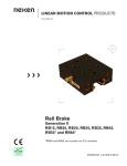
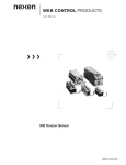
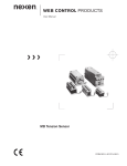
LINEAR MOTION CONTROL PRODUCTS
User Manual
Rail Brake
RB15, RB20, RB25, RB35, and RB45
FORM NO. L-21182-E-0606
In accordance with Nexen’s established policy of constant product improvement, the specifications contained in this
manual are subject to change without notice. Technical data listed in this manual are based on the latest information
available at the time of printing and are also subject to change without notice.
Technical Support: 800-843-7445
(651) 484-5900
www.nexengroup.com
DANGER
Read this manual carefully before installation and operation.
Follow Nexen’s instructions and integrate this unit into your system with care.
This unit should be installed, operated and maintained by qualified personnel ONLY.
Improper installation can damage your system or cause injury or death.
Comply with all applicable codes.
Nexen Group, Inc.
560 Oak Grove Parkway
Vadnais Heights, Minnesota 55127
ISO 9001 Certified
Copyright 2006 Nexen Group, Inc.
FORM NO. L-21182-E-0606
Table of Contents
Installation -----------------------------------------------------------------------------------------------------------------------------4
Required Tools-------------------------------------------------------------------------------------------------------------------4
Air Preparation-------------------------------------------------------------------------------------------------------------------4
Lubrication-------------------------------------------------------------------------------------------------------------------4
Air Connections-----------------------------------------------------------------------------------------------------------------5
Mounting on a Rail-------------------------------------------------------------------------------------------------------------5
Gap Adjustment-----------------------------------------------------------------------------------------------------------------6
Friction Facing Replacement----------------------------------------------------------------------------------------------------7
Service Restrictions ---------------------------------------------------------------------------------------------------------------7
Warranty -------------------------------------------------------------------------------------------------------------------------------8
FORM NO. L-21182-E-0606
INSTALLATION
Required Tools
•
•
Accessories
Clean, pressurized air
Mounting bolts and appropriate wrench
(See Table 1)
•
•
•
4 mm [5/32 inch] soft air tubing
Air valve
Quick exhaust valve (optional)
Air Preparation
NOTE: Nexen’s Rail Brake units require clean, pressure-regulated air to maintain product function. Lubricated
air may be used, but it is not required. The seals in all Nexen Rail Brakes are lubricated at the factory to ensure
optimal performance and a long product life.
WARNING
While the lubricated air will keep the seals well lubricated, it may wash away the factory
applied lubrication over time. For this reason, once lubricated air is used with a Nexen Rail
Brake, it must always be used. Discontinuing use of lubricated air may cause seal failure.
The most effective and economical way to lubricate Nexen Rail Brakes is with an Air Line Lubricator, which injects
oil into the pressurized air, forcing an oil mist into the air chamber.
Synthetic lubricants are not recommended.
AIR CONNECTIONS
DANGER
Support the load before disengaging the Rail
Brake. Failure to support the load may result
in serious injury or death.
The Rail Brake is equipped with one air inlet port used to
disengage the brake (Refer to Figure 1 for location).
NOTE: Clean air is important for proper Rail Brake
functioning. Debris inside the Rail Brake may inhibit
performance and/or decrease product life.
1. Route clean air to the Rail Brake using soft lines.
Supply adequate air pressure to ensure complete
disengagement.
Disengagement
Air-Inlet Port
NOTE: For faster engagement and disengagement,
install the valve close to the Rail Brake. Increasing air
pressures will also speed the disengagement time, but
do not exceed 6.9 bar [100 psi] air pressure.
Figure 1
FORM NO. L-21182-E-0606
Mounting on a rail
NOTE: Rail Brake must be disengaged with a minimum
of 80 psi before mounting on a rail. Apply air pressure
to disengage the Rail Brake (Refer to AIR CONNECTIONS for details).
Bolts*
Plate*
NOTE: The Rail Brake friction facing gap is set at the
factory to accommodate standard rails. If the gap is
too tight for easy installation, see the FRICTION FACING GAP ADJUSTMENT section for details. Optimum
facing gap is 0.002-0.003 inches.
Rail Brake
Bearing*
1. Apply air pressure to disengage the Rail Brake.
Rail*
2. Slide the Rail Brake onto the end of the rail, “X”-end
first. Position the Rail Brake close to its final mounting position (Refer to Figure 2).
Figure 2
NOTE: The Rail Brake does not have an internal bearing system, so it must be indirectly tied into a linear
bearing system.
3. Release air pressure to the brake before completing
step #4.
“X” end
*Customer Supplied
Plate*
Bolts*
4. Using customer supplied bolts, fasten the customer
supplied mounting plate to the Rail Brake and rail
bearing (Refer to Table 1 for Bolt Sizes) (Refer to
Figure 3 for mounting configuration).
Rail
Brake
Rail*
Bearing*
Figure 3
NOTE: Align both the Rail Brake and bearing to the
same reference edge on the plate to ensure accurate
positioning of the brake to the rail. (The optimum
facing gap is 0.002-0.003 inches.)
Table 1
Model
Bolt Size
RB15
RB20
RB25
RB35
RB45
M5 x 0.8
M6 x 1.0
M8 x 1.25
M10 x 1.5
M12 x 1.75
FORM NO. L-21182-E-0606
FRICTION facing Gap adjustment
Friction Facing Gap Adjustment may not be necessary in
all instances. Gap is factory set to accommodate standard
rail sizes. Before adjusting the gap, try sliding the Rail
Brake onto the rail. If the fit is too tight, follow the adjustment steps below.
Rail Brake
Guide
NOTE: To achieve its high force, the Rail Brake must
maintain a close fit with the sides of the rail (0.002”0.003”). The Rail Brake should have a sliding fit with
the rail. A small amount of drag should be expected.
Rail Brake Guides are threaded into the Housing and are
restricted from rotating by a Nexen label that goes between
the Housing and the Guide (Refer to Figure 4).
Nexen Label
Figure 4
1. Apply air pressure to disengage the Rail Brake.
2. Cut the label between the Housing and the Guide
using a straight edge. Leave the label in place so it
can act as a reference to the original position of the
Guide.
3. Adjust the position of the facing by turning the
Guides on each side of the Housing counterclockwise to back the Guides out of the Housing (Refer
to Figure 5).
A quarter turn should be sufficient to widen the
friction facing gap enough for the Rail Brake to side
onto the rail.
4. Slide the Rail Brake onto the rail. Position the Rail
Brake close to its final mounting position (Refer to
Figure 2).
Figure 5
5. Release the air pressure to center the brake on the
rail.
6. Using customer supplied bolts, fasten the customer
supplied mounting plate to the Rail Brake and rail
bearing (Refer to Table 1 for Bolt Sizes) (Refer to
Figure 3).
7. Apply 80 psi air pressure to the brake.
8. Turn the Guides on each side of the Housing to
achieve a .002” to .003” clearance between the rail
and the brake facing.
FORM NO. L-21182-E-0606
Friction Facing Replacement
DANGER
Support the load before disengaging the Rail
Brake. Failure to support the load may result
in serious injury or death.
Rail Brake
1. With the load supported, remove the customer
supplied bolts from the Rail Brake to free it from the
plate/bearing assembly.
Friction Facing
Assembly
2. Apply air pressure to disengage the Rail Brake.
3. Slide the Rail Brake off the rail.
Springs
4. Using an Allen wrench, remove the socket head
screws and springs that fasten each Friction Facing
to the Rail Brake and discard the old Friction Facing
(Refer to Figure 6).
Figure 6
Socket Head
Screw
5. Apply a thread locking compound to the socket
head screws.
6. Position the new Friction Facings on the Rail Brake
and hand-tighten the socket screws.
7. Follow the instructions in the INSTALLATION section to reinstall the Rail Brake.
Service Restrictions
NOTE: The Rail Brake assembly is designed for extended service life. Due to this long product life, stored spring
energy, and the complexity of the internal components, Nexen recommends that all service be performed by
trained personnel.
Do not attempt to remove or dismantle any part of the Rail Brake assembly. This product is spring loaded and
under pressure. If the product malfunctions, replace the unit or contact Nexen.
FORM NO. L-21182-E-0606
WARRANTY
Warranties
Nexen warrants that the Products will be free from any defects in material or workmanship for a period of 12 months
from the date of shipment. NEXEN MAKES NO OTHER WARRANTY, EXPRESS OR IMPLIED, AND ALL IMPLIED
WARRANTIES, INCLUDING WITHOUT LIMITATION, IMPLIED WARRANTIES OF MERCHANTABILITY AND FITNESS FOR A PARTICULAR PURPOSE ARE HEREBY DISCLAIMED. This warranty applies only if (a) the
Product has been installed, used and maintained in accordance with any applicable Nexen installation or maintenance
manual for the Product; (b) the alleged defect is not attributable to normal wear and tear; (c) the Product has not been
altered, misused or used for purposes other than those for which it was intended; and (d) Buyer has given written notice of the alleged defect to Nexen, and delivered the allegedly defective Product to Nexen, within one year of the date
of shipment.
Exclusive Remedy
The exclusive remedy of the Buyer for any breach of the warranties set out above will be, at the sole discretion of Nexen, a repair or replacement with new, serviceably used or reconditioned Product, or issuance of credit in the amount of
the purchase price paid to Nexen by the Buyer for the Products.
Limitation of Nexen’s Liability
TO THE EXTENT PERMITTED BY LAW NEXEN SHALL HAVE NO LIABILITY TO BUYER OR ANY OTHER PERSON FOR INCIDENTAL DAMAGES, SPECIAL DAMAGES, CONSEQUENTIAL DAMAGES OR OTHER DAMAGES OF ANY KIND OR NATURE WHATSOEVER, WHETHER ARISING OUT OF BREACH OF WARRANTY OR
OTHER
BREACH OF CONTRACT, NEGLIGENCE OR OTHER TORT, OR OTHERWISE, EVEN IF NEXEN SHALL HAVE
BEEN ADVISED OF THE POSSIBILITY OR LIKELIHOOD OF SUCH POTENTIAL LOSS OR DAMAGE. For all of
the purposes hereof, the term “consequential damages” shall include lost profits, penalties, delay images, liquidated
damages or other damages and liabilities which Buyer shall be obligated to pay or which Buyer may incur based
upon, related to or arising out of its contracts with its customers or other third parties. In no event shall Nexen be liable for any amount of damages in excess of amounts paid by Buyer for Products or services as to which a breach of
contract has been determined to exist. The parties expressly agree that the price for the Products and the services was
determined in consideration of the limitation on damages set forth herein and such limitation has been specifically bargained for and constitutes an agreed allocation of risk which shall survive the determination of any court of competent
jurisdiction that any remedy herein fails of its essential purpose.
Limitation of Damages
In no event shall Nexen be liable for any consequential, indirect, incidental, or special damages of any nature whatsoever, including without limitation, lost profits arising from the sale or use of the Products.
Warranty Claim Procedures
To make a claim under this warranty, the claimant must give written notice of the alleged defect to whom the Product
was purchased from and deliver the Product to same within one year of the date on which the alleged defect first
became apparent.
Nexen Group, Inc.
560 Oak Grove Parkway
Vadnais Heights, MN 55127
800.843.7445
Fax: 651.286.1099
www.nexengroup.com
ISO 9001 Certified
FORM NO. L-21182-E-0606