1
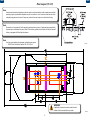
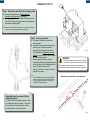
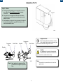
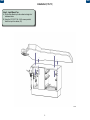
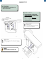
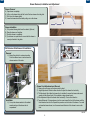
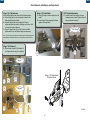
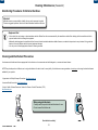
Back
Next
Artizan™ Ortho-Pedo Bench Installation / User Manual
Applies to Models:
PB250-L
PB250-R
Special Tools:
Level
3/8” Masonry drill bit
9/32” Wood drill bit
Language of origin: English
vv
Note:
If applicable, Midmark casework unit must be connected to a dedicated
circuit with disconnect rated at 10A, 115V~, 60HZ. Failure to comply
could result in an overload of the electrical circuit and/or components.
All wiring, including disconnect, and plumbing must be installed by a
licensed electrician or plumbing contractor following applicable local, city,
and national codes.
Equipment Alert
Inspect all components for shipping damages. A concealed damage
report must be filed with the carrier (by the person receiving the
goods) within 15 days of delivery.
Note:
Refer to cabinet - mounted Procenter Delivery Unit User Guide
(003-2196-00) for information on the delivery unit installed in the
Ortho-Pedo Bench.
GA1045
1
003-2203-00
Rev.D
Back
Next
Important Information and Symbols
These symbols may appear on your equipment and / or in the manuals.
WARNING
Indicates a potentially hazardous situation which
could result in serious injury if not avoided.
Caution
Indicates a potentially hazardous situation which may
result in minor or moderate injury if not avoided. It
may also be used to alert against unsafe practices
Proper Shipping Orientation
Pressure Limits
Fragile
Humidity Limit
Keep Dry
41 F
5C
100 F
38 C
Temperature Limit
Equipment Alert
Indicates a potentially hazardous situation which
could result in equipment damage if not avoided.
Consult User Guide
Note:
Amplifies a procedure, practice or condition.
Contact Information:
Midmark Corporation
115 G.L. Comer Road
Glasgow, Kentucky 42141
Phone: 1-800-643-6275 ext. 88015
Fax: (270)-651-1732
Intended Use
The Midmark Artizan Ortho-Pedo Bench can be used as the primary Pediatric
workstation, for performing pediatric dental procedures, providing the needed
storage and support at the essential delivery positions. Midmark delivery
systems are intended to provide dental professionals with air, water and suction
to operate dental handpieces, syringes, and Midmark authorized accessories
during dental examinations and procedures.
Electromagnetic Interference
Midmark dental operatory components are designed and built to minimize
electromagnetic interference with other devices; however if interference is
noticed between another device and this operatory. remove the interfering device from the room and / or plug the product into an isolated circuit.
~
AC (Alternating Current)
68kg
150 lbs
Max. Patient Weight:
68kg / 150 lbs
Type B Applied Part
No Stacking
Corrugated Recycle
Specifications
•
Approved for indoor use only.
Transportation / Storage / Operating Conditions
Transportation / Storage Temperature Range: ..0°F to 140°F (-18°C to 60°C)
Relitive Humidity:...............................................10% to 90% (Non-Condensing)
Atmospheric Pressure:.......................................7.2 PSI to 15.3 PSI (50 kPa to 106 kPa)
Operating Temperature Range...........................59°F to 95°F (15°C to 35°C)
Disposal of Equipment / Consumable Goods
At the end of this products life, the unit, accessories and other consumable goods may
be contaminated from normal use. Consult local codes and
ordinates for proper disposal of this equipment and other consumables.
2
Back
Next
Floor Layout (PB-250)
Note:
Have licensed electrical and plumbing contractors position and install electrical outlet receptacles and related
plumbing using the pre-installation template or layout. Assure floor is of such construction that the unit will be
adequately supported and anchored. If necessary contact a licensed contractor to reinforce the flooring.
Note:
Electrical box to be provided in field if required by particular delivery system. If equipment being supplied with
the pedo bench is a Midmark Procenter (Ortho & Pedo delivery system) then this option will only be required if
delivery is equipped with Fiber Optic Handpieces.
Note:
A full size, pre-installation floor template is available upon request:
• PB250 Ortho-Pedo Bench Cabinet, P/N: 003-2142-00
GA1003
WARNING
If applicable, electrical box must be installed under
cabinet as far from water bottle as possible.
GA1006
3
Back
Next
Installation (PB-250)
Step 1: Remove the Pedo Bench from shipping pallet
A) Remove cabinet drawers (see Drawer Removal,
Installation, and Adjustment in this manual).
B) Accessing under the cabinet through false bottom cutouts
use a 3/8” socket to remove lag screws securing base clips
and cabinet to shipping pallet
Note: Be sure to save base clips and lag screws to use later in the installation
process to secure the cabinet to the floor of the building.
Step 2: Securing the cabinet
A) Set cabinet in desired location over the
utility provisions.
B) Using a level as necessary, unscrew the leg
levelers using a flat head screwdriver
through the hollow leg bolt in the bottom
of the cabinet (see Adjustable Camar Leg
Leveler) or by hand through the false bottom
cutout until cabinet is level.
C) Use the lag screws (if floor is made of
composites) and base clips that were used to
secure the cabinet to the shipping pallet and
secure the cabinet to floor of the
building. If the floor is concrete, then utilize
supplied floor anchors.
Note:
To make installation easier and to prevent damage to
area surrounding screw hole in floor, drill pilot holes.
Use a 3/8” masonry drill bit for concrete and a 9/32” wood drill bit for composite flooring.
GA1046
WARNING
Cabinet weighs approximately 188 pounds. Lift with
two people on the bottom edge of the cabinet. Only
lift the cabinet in designated locations after drawers have
been removed. See above illustration for proper lifting points.
Base Clip Removal / Installation
GA1022
Adjustable Camar Leg Leveler (Cabinet
Height Adjustment)
A) Utilize a flat head screwdriver and place down
into hollow bolt in bottom of cabinet. Turn screwdriver clockwise to extend leg to floor, and turn
counterclockwise to adjust leg off of floor.
GA1010
4
Back
Next
Installation (PB-250)
Step 3: Utilities
A) Attach appropriate plumbing such as cold water, air, vacuum, etc... (refer to the Technical Reference Guide for routing
information.)
B) If the pedo bench is equipped with Fiber-Optic Handpieces,
electrical provisions must be made and connections must be
made at this time.
C) Feed handpieces, syringes etc. through grommet at the head of
the cabinet and hang on the appropriate holder bars on the
doctors and assistants doors.
GA1048
Equipment Alert
Regulator
Compression
Fitting
Shutoff Valve
Regulator
Compression
Fitting
Shutoff Valve
When changing water bottle container, be sure door
is fully opened so that the bottle is not above any part
of the cabinet so that water damage does not occur.
Caution
It is imperative that the location of the water bottle
mounted inside the cabinet not be moved from the
location at which it was installed from the factory.
Note:
If a water bottle is not provided be sure to close the air
regulator valve.
Step 4: Insert regulator into compression fitting
of shutoff valve and tighten compression
fitting.
5
Back
Next
Installation (PB-250)
Step 5: Install Bench Top
A) Set the Pedo Bench top on the cabinet and align the 4 attachment holes.
B) Using the 1/4”-20 X 2” P/N: S19153 screws provided, fasten the top to the cabinet. (X4)
GA1009
6
Back
Next
Installation (PB-250)
Step 6: False Bottoms
A) Unwrap false bottoms and install into bottom of the
cabinet to cover access points.
Step 7: Doors and Drawers
A) Re-install cabinet drawers (see Drawer Removal,
Installation, and Adjustment in this manual) and make
adjustments as needed.
B) Adjust doors accordingly (see Door Removal,
Installation, and Adjustment in this manual).
Equipment Alert
Be sure to adjust drawer adjustments to the down
position before re-installing drawers.
B
GA1011
Equipment Alert
Maximum recommended weight for contents in drawers is 5lbs for
medium (3.15” HGT) drawer boxes and 10lbs for large (5.9” HGT)
drawer boxes.
WARNING
Maximum patient load must not exceed 68kg / 150lbs
GA1049
7
Back
Next
Drawer Removal, Installation and Adjustment
Drawer Removal
A)
B)
C)
D)
Open drawer completely.
Lift up on the drawer front until the front of the box releases from the glide.
Pull out on the drawer slightly.
Lower the drawer back down while pulling out on the drawer.
C
D
B
A
Drawer Installation
A)
B)
C)
D)
Fully extend drawer glides from the cabinet. (Optional)
Place the drawer on the glides.
Push the drawer in completely.
Cycle drawer a couple times to ensure that the drawer is
securely attached to the glides.
GA1106
2
Full Extension Glide Removal & Installation...
Removal
4
Cabinet Member
A) Extend the glide to its outermost position.
Push the release levers in and remove the
drawer member of the sides.
Drawer Member
PULL
Installation
PUSH
A) Line up the drawer member to the cabinet
member and push the drawer into its
compartment.
3
5
GA1107
Drawer Front Adjustment and Removal
1) Remove the cover caps on the drawer side by hand.
2) Height Adjustment: Rotate in either direction to adjust the drawer front vertically.
3) Tilt Adjustment: Adjust after the drawer front is installed to ensure the drawer sides meet
square with the drawer front. (Only available on large drawer boxes.)
4) Side Adjustment: Adjusts the drawer front horizontally. Turn in either direction.
5) Tension/Removal: For large drawers, turn the screw toward the front of the drawer until the
front detaches from the box. Repeat this procedure on both sides of the drawer. For small
and medium drawer boxes, turn the screw toward the back of the drawer to remove the
front.
GA1105
8
Back
Next
Door Removal, Installation, and Adjustment
Hinge 1 & 2 Adjustments
Use a phillips head screw driver for the following steps...
A) Screw A adjusts the door in direction A seen in the
Adjustment Direction Guide
B) Screw B adjusts the door in direction B. Equal
adjustment must be made to all hinges on the door for it
to move the desired distance.
C) Screw C adjusts the door in the C direction. Make
adjustments to top and bottom hinge as necessary.
Hinge 1 & 2 Installation
180° Hinge Adjustments
F) Hook the hinge to the mounting block at
point F
G) Latch at point G by pressing the hinge
against the hinge block.
D) Loosen screw D and adjust door gap
and angle using a level. Tighten screw D
when positioned correctly,
180° Hinge
Note: Use a level to ensure the door is level and plumb. Preferred gaps are
approximately 1/8” between doors and 1/16” between accents and doors.
F
Hinge 1 & 2 Removal
E) Press button at point E at the back of
the hinge and pull away from cabinet.
B
E
D
G
Hinge 1
A
Hinge 1 & 2 Adjustment
Direction Guide
C
E
Hinge 2
A
C
B
C
A
GA1044
B
9
Back
Next
Cleaning / Maintenance (Casework)
Disinfecting Procedures for External Surfaces
Attention!
Midmark assumes no responsibility or liability for any result, expressed or implied.
These are suggested practices, based on the best information available at this time.
Equipment Alert
• Users should not use cleaning or decontamination methods different from those recommended by the manufacturer without first checking with the manufacturer that the
proposed methods will not damage the equipment.
• Midmark’s dental equipment is manufactured from the most chemical-resistant materials available. However, no material is impervious to every chemical. Using protective
barriers is the most effective method to prevent equipment damage.
• Use only moist cloth with appropriate cleaner for cleaning casework.
Cleaning and Disinfectant Procedures
Use cleaners and disinfectants that are appropriate for the situation such as warm water and mild detergents, or an ammonia based cleaner.
NOTE: Every dental practice is different, and no single disinfectant is the best choice for every facility. Listed below are some organizations to assist you in choosing the best disinfectants
available for your practice.
• Organization for Safety & Asepsis Procedures: http://www.osap.org
• American Dental Association: http://www.ada.org
• Dept. of Health & Human Resources Centers for Disease Control & Prevention (CDC):
http://www.cdc.gov
When using disinfectants...
Carefully read the product label and directions for use.
Do not exceed the dilution rate.
Read all labels carefully!
10
Back
Next
Midmark Corporation
For additional contact information, go to:
www.midmark.com
11