1
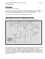
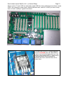
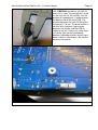
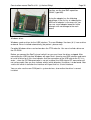
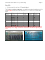
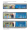
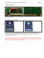
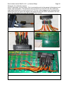
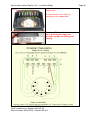
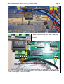
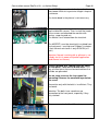
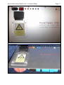
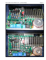
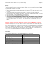
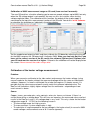
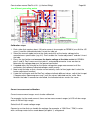
Construction manual RoeTest V8 - (c) Helmut Weigl
Page 63
Current limiter:
The RoeTest uses hardware current limiters to limit the current output as per the table below:
Heater low range
Heater high range
Anode/plate
G2
max. current (design)
ca. 5000 mA (maximal)
500 mA
255 mA
51 mA
Current limiter kicks in at
ca. 6000mA
ca. 670 mA
ca. 350 mA
ca. 68 mA
Note that the actual values at which the current limiter takes effect depend on the
tolerances of the semiconductors and the resistors. The transformers used should be able
to continuously deliver about 1.25 times the maximum current.
To test the hardware current limiters:
Test the heater, anode and G2 voltage boards, one after the other:
-> connect a suitable resistor that can handle the load, or if you don’t have one use for
instance a light bulb to test point 1 and ground and increase the output voltage until the
current limiter kicks in. Do this only for a short period of time! Output voltage should decrease
when the current limiter kicks in and the output current should not further increase.
Note: make sure to use 5W wire wound resistors for the current measurement and current
limiter circuits – other resistor types repeatedly failed on me.
To test voltage regulation of the H, A and G2 boards:
From Roetest 4 onwards electronic voltage regulation is used. Output voltages must remain
stable as long as the output current limiter does not kick in. Connect a resistor and verify the
output voltage is constant.
Continuity test circuits:
The continuity test circuit is used in various tests – for instance for the filament test or when
testing for shorts.
Verify the function of the continuity circuit with no tube inserted. The continuity test circuit uses
the S2 (A) and S4(G2) rails. When the “check for continuity” relay is switched on 5V is fed
through a resistor and diode (for protection) is connected to the S4 rail and should be
measurable. Switch the relay on using the software as shown (PC software->Options/Test>Relays->check for continuity). Now connect the S2 and S4 rails.
This can be done by removing a relay card and using a wire to connect the S2 and
S4 rails in the card socket on the motherboard. The causes the MPSA44 to be switched on
and the signal B7 at the PIC goes from hi to lo. The software should
indicate that by illuminating the software LED “check for continuity” as shown below.