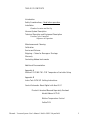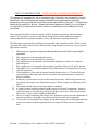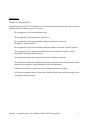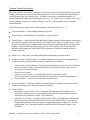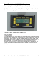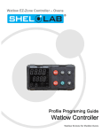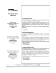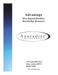
1
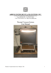
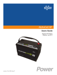
A B B ESS I NST R U M E N TS A N D SYST E MS, I N C.
P.O. Box 498, ASHLAND, MASSACHUSETTS 01721
Phone (508) 881-8811 Fax (508) 881-4884
E-mail [email protected] http://www.abbess.com
Thermal Vacuum System
User Manual
|
Thermal – Vacuum System User’s Manual –NASA GSFC~Heymsfield
1
T A B L E O F C O N T E N TS
Introduction
Safety Considerations – Read before operation
Installation
Chamber Location and Set-Up
V acuum System Description
T echnical O peration and E quipment Description
Vacuum Cycle Controller
Sequence of Operation
M aintenance and C leaning
C alibration
Service and Returns
Shipping – C laims for Damage or Shortage
W ar ranty
Contacting A bbess Instruments
A dditional Documentation
A ppendix A
W atlow E Z-Z O N E P M – PI D T emperature Controller Setup
A ppendix B
Instru T ech C V M 301 -Setting Instructions
Control Schematic: Basic Digital with H eat V C C
Product L iterature/M anuals Separately E nclosed
A lcatel/A dixen A C P-40
W atlow T emperature Control
V albia P A V
Thermal – Vacuum System User’s Manual –NASA GSFC~Heymsfield
2
INTRODUC TION
Abbess Instruments’ Thermal Vacuum Chamber Systems are designed and produced for use in production and testing applications requiring an exposure to or process within a controlled vacuum
environment at specific temperature. The chambers are often custom designed for specific end-user
requirements in recreating extreme atmosphere and temperature situations. Our customers use our
full range of vacuum systems for testing or degassing packaged products, liquids and solids, EMI
and altitude testing of electronics, computers and complete systems, shock impact targets, plasma
science, space simulation and degassing large parts or components for research, and development.
Abbess designs rugged equipment for continuous manufacturing and production use, with safety and
a long life in mind. The Vacuum chambers are constructed of heavy aluminum, steel or stainless
steel. They have customer replaceable O-ring seals which are designed to withstand repeated
closings. Two latches are used to close the standard front-hinged door. All cube chambers are He
leak tested to a rate of 10e-7 cc/sec or better as required and should maintain this for its life
dependent on seal condition and customer use.
Most Vacuum Chamber systems are made up of these basic functional components:
Chamber: a vacuum container or chamber.
Pump: a vacuum pump or other means of creating a vacuum.
Hose: a hose, plumbing or tubing needed to connect the chamber to the pump.
Valves: to control vacuum and release/break the vacuum.
Vacuum Pressure Gauge: to measure actual pressure inside the chamber.
Monitoring and control of the systems are attuned to specified process needs and configured to both
optimize the end use operation time and assure the proper cycling of vacuum equipment. Visual
monitoring of the Chamber interior is made possible through a view window in the chamber door or
clear acrylic door construction. Vacuum and thermal systems are integrated into the overall system
control allowing for continuous operator involvement in operations within the chamber.
Thermal – Vacuum System User’s Manual –NASA GSFC~Heymsfield
3
SA F E T Y C O NSI D E R A T I O NS – R E A D T H IS SE C T I O N B E F O R E O PE R A T I O N
T his equipment is designed for use in manufacturing or laboratory environments by trained
technicians. Use of this equipment beyond its stated intended purpose and operating
parameters is not recommended and will be the sole responsibility of the user. T his equipment
should not be modified or altered. A bbess Instruments assumes no liability for any misuse of
or modification to this product and such misuse or modification will immediately void all
war ranties.
This equipment should be used in accordance with the operating instructions contained in this
manual. For alternative uses not covered in this manual, please contact Abbess Instrument’s technical department for product suitability, safety, and alternative operating instructions.
The following are general safety guidelines recommended when using this product. Please consult
your laboratory safety officer for any additional safety steps that may be necessary for your specific
application or material.
M ake sure your operator reads and understands this manual before operating the
equipment.
2. This equipment is to be operated indoors only.
3. This equipment is to be operated in a well-lit area.
4. This equipment is to be operated with an ambient temperature of between 10 degrees C
and 40 degrees C.
5. This equipment is to be operated with an ambient humidity of between 20 and 85 percent.
6. Thoroughly review your MSDS (Material Safety Data Sheets) for all chemicals to be used
with this equipment.
7. If the equipment is fitted with an optional internal thermal source (i.e. Thermal Plate) the
user must ensure that temperatures do not exceed the auto ignition point(s) of materials
placed in chamber.
8. Hand and eye protection are required when using this product. Additional protection may
be required with respect to the materials being used. Please consult your laboratory safety
officer.
9. This product should only be used with adequate ventilation.
10. A trained electrical technician should conduct repairs of electrical components. Incorrect
replacement parts or assembly may damage the product and create a serious safety hazard
for the user. Factory repair is highly recommended.
11. The use of samples containing ether based, fuel, munitions, or other extremely flammable or
explosive materials, compounds, or residues should not be used in this equipment.
12. Use of acidic or base material may damage this product and are not recommended unless the
product was ordered with the optional protective coating in Teflon or made of Stainless
steel.
1.
Thermal – Vacuum System User’s Manual –NASA GSFC~Heymsfield
4
Installation
Chamber Location and Set-Up
Equipment must be SET-UP and installed in a LOCATION meeting the following criteria and with
attention paid to the following areas of concern:
-
This equipment is to be operated indoors only.
-
This equipment is to be operated in a well-lit area.
-
This equipment is to be operated with an ambient temperature of between
10 degrees C and 40 degrees C.
-
This equipment is to be operated with an ambient humidity of between 20 and 85 percent.
This equipment is to be operated on a stable floor, deck, or platform capable of safely
supporting it and the intended operation.
-
This equipment maybe secured to the floor, deck or platform as required.
-
Electrical power connections should be provided as required by licensed professional trades
people and in compliance with all applicable codes and ordinances.
-
Adequate ventilation for people, process, and equipment must be provided.
-
All system components must be assembled, calibrated, tested, and secured as needed for the
safe and specified operations.
Thermal – Vacuum System User’s Manual –NASA GSFC~Heymsfield
5
Vacuum System Description
The Abbess/NGSFC-Heymsfield Thermal Vacuum System allows items placed inside to be exposed
to high vacuum pressure as well as extreme temperatures via the electrically heated and refrigerant
cooled Thermal Plate and Shroud System. The entire system can be controlled manually, by
starting/stopping the pump(s) and opening/closing valves. A Vacuum Cycle Controller (VCC) can is
used to automate vacuum cycle control functions. The VCC enables system control via panelmounted buttons.
The Vacuum System consists of the following major components (See Figs. 1 - 7):
Vacuum Chamber - A front loading Stainless Steel Cube
Vacuum Pump- Alacatel/Adixen ACP40 Roots Type Dry Pump
Thermal Plate – Copper Thermal Plate and Shroud System mounted within chamber with heating
elements and separate closed loop cascade refrigerant and open loop N2 cooling systems. Feedthrough for electrical power, thermocouple and cooling lines extend through the rear wall of the
chamber. The plate allows heating/cooling of items in the chamber under vacuum and the
different cooling modes are controlled by PID temperature Controllers mounted in Process
Control Enclosure.
Mobile Cart – Heavy-duty cart/stand with chamber and pumping system mounted.
Thermal Vacuum Control Enclosure – Contains component necessary for controlling thermal
systems as well as logic and interfaces for the Vacuum Cycle Controller.
Vacuum Gauge Control Register – Provides pressure display per remote Pressure Transducer
and set point value control. Also provides pressure set-point relays that can be used for
various system control functions.
Process Timer Control
Vacuum Cycle Controller – Control ON/OFF buttons, main power switch.
Watlow Temperature Controllers and Limits(See manufacturer specific documentation).
Status Indicators – Provide visual indication of system status.
Pressure Transducer – Pressure Transducer attached directly to chamber communicates sensor
readings to remote pressure display/interface at Controller.
Control Valves
Automatic Vent & Vacuum Valves – Automatic Electromagnetically actuated valves
evacuate the chamber (via the vacuum pump system) and vent air into chamber based on
control input from Thermal Vacuum Cycle Controller.
Automatic Cryo Valves – Automatic solenoid valves allow refrigerant gas into the engaged
piping system at the Thermal Shroud. Flow of LN2 to the Thermal Plate is regulated via
Proportionally Actuated Valves serving two engaged piping loops arranged in a cross flow
configuration. Valve actuation is based on control input from Theramal Vacuum Cycle
Controller.
Thermal – Vacuum System User’s Manual –NASA GSFC~Heymsfield
6
Clear Acrylic Door
At S.S. Cube Chamber
Thermal Vacuum Cycle Controller
Thermal Plate and Shroud System
(shown w/shroud front plate removed)
Closed Loop Cascade
Refrigeration System
mounted below.
Mobile Caster Cart
Figure 1 – Front View of Thermal Vacuum System
Figure 2 – Detail View of Thermal Vacuum Control
Thermal – Vacuum System User’s Manual –NASA GSFC~Heymsfield
7
Cryo Solenoid Valve
(LN2 Supply to Shroud)
Power/T-CPL Feedthru
For Thermal Plate and Shroud
(shown w/o enclosure)
Vacuum Manifold
W/Solenoid Vent and ElectroMag
Right Angle Vacuum Valve
(Hose connect to pump not shown)
PAV Cryo Valves
At Feedthrus for LN2
To Thermal Plate
Insulated Line from
Closed Loop Cascade
To Thermal Plate
Alcatel/Adixen ACP-40
Dry Roots Pump
Figure 3 – Rear View of Thermal Vacuum System
Figure 4 – Detail View of Vacuum Manifold
Thermal – Vacuum System User’s Manual –NASA GSFC~Heymsfield
8
Figure 5 – Rear View of Thermal Vacuum System (Protective Enclosures shown)
Vacuum Pressure Sensor
Process Ports
(Feedthru TBD by Customer)
Rear of TVCC Enclosure
Figure 6– Detail View of Vacuum Pump
Thermal – Vacuum System User’s Manual –NASA GSFC~Heymsfield
9
Power Indicator and Switch
Plate Fault Test Switch
Vacuum Gauge Controller
Emergency Stop
Process Indicators
Start and Stop Button Controls
Figure 7– Thermal Vacuum Cycle Control Detail
Plate and Shroud Process Indicators
New PM6 Controllers and Limits
for Plate and Shroud LN2 Systems
Note: Toggle provided switches between
plate cooling modes (LN2/Refrigeration)
Thermal – Vacuum System User’s Manual –NASA GSFC~Heymsfield
10
Thermal Vacuum Cycle Controller - Theory of Operation
The system’s pressure level is controlled via setpoint management by the InstruTech VGC
301 controller, opening and closing solenoid and electromagnetically actuated right angle
valves at the vacuum manifold at rear of the chamber. Evacuation of the chamber is
facilitated by the Alactatel/Adixen ACP-40 Dry Roots Type Vacuum Pump. Vacuum Cycle
Soak Time is regulated by an Eaton TRL04 timer internal to the control enclosure.
The system’s temperature is controlled by three (3) Watlow PID controllers. The temperature
of the thermal plate within the chamber can be controlled by either the PM6 Watlow labeled
“Nitrogen” on the far left of the control box or by the F4 Watlow labeled “refrigerator” located in the center of the control box. Both controllers use the same circuitry to heat the
plate and are monitored by the same limit Watlow that will cut power to both Watlows if
temperatures reach unsafe levels. In addition to the Limit Controllers a manual toggle Plate
Fault Test switch also interrupts power.
o The PM6 Watlow on the left of the control box uses two liquid nitrogen cooling
circuits configured in a counter flow configuration and metered by proportioning
valves to rapidly cool the thermal plate to as low as -180C.
o The F4 Watlow manages a cascade refrigerator to cool the plate to -80C without
using any liquid nitrogen.
Control of the thermal plate can be switched between the two Watlows using the switch
located between the two Controlers. When refrigeration control is selected, the refrigerator
will constantly run in conditions below 20C and will only turn on as needed at temperatures
above 20C. It should be noted that the low temperature compressor of the refrigerator is on a
time delay so the user may not see cooling immediately after set point change.
The thermal shroud is controlled and monitored separately by its own PM6 and limit
Watlows located on the right side of the control box. The PM6 controller uses a liquid
nitrogen circuit controlled by normally closed solenoid valves to cool the thermal shroud and
rod heaters the heat the shroud independently of the thermal plate.
Thermal – Vacuum System User’s Manual –NASA GSFC~Heymsfield
11
Thermal Vacuum Cycle Controller - Sequence of Operation
1. The operator can load the open chamber at atmospheric pressure and ambient temperature.
2. Secure the chamber with the latches.
3. Close and check all manual vent valves.
4. All the temperature and pressure and process timer parameters are pre-set and tested before
shipment. (Setup for each Watlow Controller is attached in Appendix to this manual. Refer to
component product literature [pdf files provided on CD] for further detailed instructions.)
5. On the Thermal Vacuum Cycle Controller (grey panel) switch on the POWER.
- The power light indicator will turn on. (YELLOW)
- Temperature Controllers (Watlow EZ-Zone PM and Limits) will turn on.
- Pressure Controller (Instrutech- VGC-301) will turn on.
- The operator may enter temperature set points using the Up and Down arrow on the
Temperature Controllers.
6. On the Vacuum Cycle Controller (grey panel) press the START button (Green).
- The Pump will begin to pump down the Chamber.
7. To stop the system operation press the STOP button (Red) on the Vacuum Cycle Controller
(grey panel). The pump will shut down.
NOTE: Opening to the chamber to lab/atmosphere conditions with thermal elements at
extreme temperature can cause damage to system components and introduce debris and
contaminants to the chamber environment.
Once the chamber pressure and temperature have reached levels equivalent with ambient
conditions it is safe to open and access the chamber.
Thermal – Vacuum System User’s Manual –NASA GSFC~Heymsfield
12
Maintenance and Cleaning
Cleaning the Stainless Steel Components - The Stainless Steel components may be cleaned with a
cleaner approved for use with Stainless Steel. Non-abrasive cleaners are recommended to preserve
the surface finish. Non-abrasive scouring pads are recommended. Scrapers and non-metallic
scouring pads may be used on heavily soiled areas. If scrapers are used caution must be used to not
damage the chamber surface. Rinse all areas with water using a sponge or towel. Dry thoroughly.
NOTE: DO NOT RINSE ELECTRICAL EQUIPMENT UNDER RUNNING WATER!!!
Recommended Cleaning Agents (Cannot contain oil)
Sheila Shine – Stainless Steel cleaner and polish
Simple Green – All purpose cleaner
Orange Clean – All purpose cleaner
non-abrasive
non-abrasive
non-abrasive
Decontamination – No hazardous materials are used in this equipment. In the event of a hazardous
material spill by the user or outside source, immediately contact your laboratory safety officer or the
manufacturer of the material for instructions on clean up or other decontamination procedures.
Reference your Material Safety Data Sheets (MSDS) for instructions on proper clean-up and
handling procedures.
Calibration
Calibration of all components is subject to user’s internal calibration standards.
Thermal – Vacuum System User’s Manual –NASA GSFC~Heymsfield
13
Service and Returns
In the event a product purchased from Abbess Instruments needs service or must be returned please
follow the outlined procedures below
Contact Abbess Instruments Technical Support Department
Before returning any product to Abbess Instruments for any reason, please contact Abbess
Instruments at 508-881-8811. Support is available Monday through Friday from 8:30 AM to
5:00 PM EST. Support is available free of charge to customers of Abbess Instruments in good
standing for all products sold by Abbess Instrument.
Pack the Product for Return Shipment
The product should be packaged in its original shipping carton or crate if available. If other
packaging is required, use a suitable shipping container, which will allow a minimum of 2
inches clearance between the product and the walls of the shipping carton or crate. Peanuts,
semi rigid foam, cardboard, and other items may be used inside for packaging. Care should be
taken when packaging heavy items. Some packaging, such as peanuts, will allow the item to
shift in transit and may result in damage.
Insurance
Most common carriers offer insurance. UPS and Federal Express automatically insure your
product up to $100 without charge. It is highly recommended that you insure your product.
Abbess Instruments is not liable for any return shipping damages.
Documentation
When returning items to Abbess Instruments, a packing slip or other document must be
included with the following information: Contact person’s name and phone number, return address, and statement of the problem.
How Will Your Return be Handled?
Abbess Instruments will evaluate the returned item for damage. If the return is a repair, the
product will be examined for problems and a repair estimate will be made. The contact person
will be contacted, at which time a Purchase Order will be requested. After the PO is issued, the
product will be repaired and return shipped. The repair will be done in an expeditious manner.
The contact person will be notified immediately in the event any shipping damage has
occurred.
Thermal – Vacuum System User’s Manual –NASA GSFC~Heymsfield
14
Shipping – Claims for Damage or Shortage
Abbess Instruments makes a sincere effort to ensure your purchase is properly packed and all items
listed on the packing slip are in fact enclosed with the shipment. In the event that your purchase is
damaged or if any items are missing, please follow the procedures below.
All packaging material must be retained until the issue is resolved.
Thoroughly search all packing material for missing items. Review your packing list for back
ordered items and the manual for a list of items affiliated with your purchase.
Contact Abbess Instruments immediately at 508-881-8811.
Carrier is responsible for breakage in transit! Goods shipped by Abbess Instruments were delivered
to the carrier in good condition. They were packed with great care using standard approved
packaging methods.
If you receive damaged goods, please follow these steps so that we can ensure proper credit to you:
Contact the carrier damage inspection. Hold original carton and merchandise for the inspector.
Please notify Abbess Instruments immediately—(508) 881-8811. DO NOT return damaged
goods to Abbess Instruments without authorization. DO NOT return goods that have not been
inspected by the carrier.
We are willing to assist you in every possible manner, but please be aware that if you fail to follow
the above procedure, the freight carrier or Abbess Instruments may not honor your claim
Thermal – Vacuum System User’s Manual –NASA GSFC~Heymsfield
15
ST A N D A R D W A R R A N T Y
ABBESS INSTRUMENTS PRODUCT (THE UNIT) WAS CAREFULLY TESTED AND INSPECTED BEFORE
LEAVING THE FACTORY.
WE WARRANT THIS PRODUCT TO BE FREE FROM DEFECTS IN MATERIAL AND WORKMANSHIP UNDER
NORMAL USE AND SERVICE FOR 12 MONTHS FROM THE DATE OF RECEIPT, WITH THE FOLLOWING
EXCEPTIONS:
ABBESS ACRYLIC LIDS AND ACRYLIC VACUUM CHAMBERS ARE DESIGNED TO BE ROBUST,
HOWEVER DUE TO THE NATURE OF ACRYLIC, ARE NOT MEANT TO WITHSTAND BEING DROPPED,
HAVING A POINT LOAD PLACED OF THEM OR WITHSTANDING SHARP BLOWS. THEY ARE ALSO
PRONE TO BECOMING SCRATCHED AND ABRADED, ESPECIALLY WHEN CAUSTIC SAMPLES ARE
PLACED INSIDE OF THE CHAMBER OR WHEN SOLVENTS CONTAINING CAUSTICS OR ABRASIVES ARE
USED TO CLEAN THE ACRYLIC COMPONENTS OF THE CHAMBER. FOR THESE REASONS ABBESS WILL
ONLY WARRANTY THESE ACRYLIC PARTS FROM DEFECTS IN THE WORKMANSHIP AND THE
MATERIAL THEMSELVES, BUT NOT FOR ANY EFFECTS OF MISHANDLING OR OTHERWISE NORMAL
USE THAT CAN BE DETRIMENTAL TO ACRYLIC.
ALL REFRIGERATION/COOLING UNITS ARE WARRANTEED FOR NINETY (90) DAYS.
THE COMPONENTS OF ABBESS VACUUM CHAMBER SYSTEMS ARE, BY THEIR NATURE, DELICATE.
ABBESS INSTRUMENTS STRONGLY RECOMMENDS THAT ALL SYSTEMS CONTAINING ELECTRONICS
BE SHIPPED BY AIR. ABBESS CANNOT BE RESPONSIBLE FOR COMPONENTS BECOMING LOOSE OR
DAMAGED DURING TRANSIT. WE HAVE FOUND THROUGH OUR EXPERIENCES THAT REGARDLESS OF
HOW WELL ELECTRONICS ARE PACKED FOR SHIPPING THEY ARE PRONE TO DAMAGE. FOR THAT
REASON WE WILL ONLY SHIP SYSTEMS CONTAINING VACUUM COMPONENTS AND ELECTRONICS VIA
AIR UNLESS SPECIFIED OTHERWISE BY THE CUSTOMER. IF A CUSTOMER CHOOSES TO SHIP
ANOTHER MODE OF TRAVEL THE CUSTOMER MUST TAKE FULL RESPONSIBILITY, IN WRITING, FOR
ANY DAMAGE INCURRED IN SHIPPING.
WARRANTIES WILL BECOME VOID IF VACUUM CHAMBERS ARE KEPT IN AN ENVIRONMENT THAT
CAUSES CONTAMINATION TO THE CHAMBER AND ANY OPERATING DIFFICULTIES CAUSED BY DIRT
OR CONTAMINATION WILL NOT BE COVERED BY WARRANTY.
IN THE EVENT OF DEFECT IN MATERIALS OR WORKMANSHIP, WE WILL EITHER REPAIR OR REPLACE,
AT OUR OPTION, ANY PART WHICH IN OUR JUDGMENT SHOWS EVIDENCE OF SUCH DEFECT.
THIS WARRANTY DOES NOT COVER WEAR OR EXPENDABLE ITEMS SUCH AS GASKETS/ORINGS/GASKETS OR OIL. THIS WARRANTY DOES NOT APPLY IF, IN OUR OPINION, THE UNIT HAS
BEEN MISUSED, ABUSED, ALTERED, TAMPERED WITH, OR USED IN LIFE-CYCLE TESTING. ABBESS
WILL ONLY BE RESPONSIBLE UP TO THE COST OF THE UNIT. THIS WARRANTY DOES NOT COVER ANY
CONSEQUENTIAL DAMAGES. AT THE END OF THE WARRANTY PERIOD, ABBESS SHALL BE UNDER NO
FURTHER WARRANTY OBLIGATION EXPRESSED OR IMPLIED.
FOR THIS WARRANTY TO BE VALID A COPY OF THE PACKING LIST MUST BE SIGNED, DATED AND
RETURNED TO ABBESS WITHIN 2 DAYS OF RECEIPT OF THE UNIT.
FOR SERVICE PLEASE REQUEST A RETURN MATERIAL AUTHORIZATION (RMA) NUMBER FROM
ABBESS BY CALLING 1-508-881-8811 AFTER AN RMA HAS BEEN ASSIGNED, SHIP THE UNIT, FREIGHT
PREPAID,IN THE ORIGINAL CRATING, PREPAID.
THERE WILL BE A CHARGE FOR ALL REPAIRS MADE THAT ARE NOT, UNDER ABBESS JUDGMENT,
MADE AS WARRANTY REPAIRS.
Thermal – Vacuum System User’s Manual –NASA GSFC~Heymsfield
16
CONTACTING ABBESS INSTRUMENTS
Shipping Address:
Abbess Instruments and Systems, Inc.
70 Bartzak Dr.
Holliston, MA 01746
USA
Mailing Address:
Abbess Instruments and Systems, Inc.
PO Box 498
Ashland, MA 01721
USA
Phone: 508-881-8811
Fax: 508-881-4884
Email: [email protected]
Thermal – Vacuum System User’s Manual –NASA GSFC~Heymsfield
17
A ppendix A W atlow E Z-Z O N E P M – PI D T emperature Controller setup
Note – Please read EZ-ZONE PM User’s Manual for detailed information.
The setup menu for the PM6 Watlow is reached by pressing the up and down arrow keys at the same time for
6 seconds until “set” appears in green. The arrow keys can then be individually used to move throughout the
menus and the green button can be used to select which menu you would like to enter. The infinity key is used
to go back to the previous menu. The F4 set up is reached through the scrolling through the LCD screen using
the up and down arrow keys and using the right and left keys to enter and exit menus respectively.
For each of the Watlows the setup is as follows:
Nitrogen:
Set up: Ai(analog input):
SEn(sensor):tC(thermocouple)
Lin(linearization):H(K)
FiL(Filter):0.5
i.Er(error latching):off
dEC(decimal places):0.0
i.CA(calibration offset):0.0
CoM(communications): unused unless data logging
is required (all defaults) gLbL(Global):
C_F(display units):C
Everything else is default
Thermal – Vacuum System User’s Manual –NASA GSFC~Heymsfield
18
(Nitrogen Setup Continued)
Fun(Function Key): unused(all defaults)
ALM(alarm): unused(all defaults)
Otpt->1(Output 1):
O.ty (Output type): Volts
Fn (function):Cool
Fi (functional instance): 1
S.Lo (scale low):0
S.hi (scale hi): 10
r.Lo (range low):0%
r.hi (range hi):100%
o.CA (calibration offset):0
Otpt->2 (Output 2):
Fn (function):Heat
O.ct (output control): v.tb(variable time base
o.Lo (low power scale):0%
o.hi (hi power scale): 100%
Loop:
h.AG (heat algorithm): Pid(Proportional, Integral, Derivative)
c.AG (cool algorithm):Pid(Proportional, Integral, Derivative)
C.Cr (cool output curve):Off
PIDs will vary depending on tuning see manual for details
Db(dead band):1
t.tun (TRU-TUNE+TM): Off
A.tSP (autotune at setpoint):100%
t.AGr (tuning aggressiveness): Crit(critical)
P.dl (Peltier Delay):0
UFA(User Failure Action): USEr
FAIL: USEr
L.dE (open loop detection):no
Rp (ramp):off
L.SP (Low Set Point): -200
H.SP (High Set Point):120
C.SP(closed loop setpoint): whatever you are trying to get to (same as green number
on main)
Id.S(idle setpoint): 24
SP.Lo(set point open limit low):-100%
SP.hi(set point open limit hi):100%
C.M(command mode): auto
Pv(process value): unused(all defaults)
Lnr(linearization): unused(all defaults)
Thermal – Vacuum System User’s Manual –NASA GSFC~Heymsfield
19
Refrigeration
Setup:
System:
PID units: SI
F or C: C
Yes for upper display
Max heat trans: 100%
Max transfer cool:0%
Man to auto trans: restore setpoint
Ch1 autotune SP: 90%
Failuremode: bumpless
Open loop ch1: off
Analog input:
Sensor: thermocouple
Type: K
Decimal: 0.0
SP low limit: -90
SP hi limit: 120
Offset type: tingle linear
Calibration offset: 0
Filter time: .5
Error latch: self clear
Digital Inputs: all unused (defaults)
Control output 1A
Function: Heat(reverse)
Cycle time: fixed time
Cycle time: 1 sec
Hi power limit:100%
Low power limit:0%
Thermal – Vacuum System User’s Manual –NASA GSFC~Heymsfield
20
(Refrigeration Setup Continued)
Control output 1B
Function: Cool(direct)
Cycle time: fixed time
Cycle time:60sec
Hi power limit:100%
Low power limit:0%
Alarm output 1:
NAME:HONLY
Type: process
Source: input1
Latching: self-clears
Silencing: yes
Hysteresis:1
Alarm sides: high
Logic: open on alarm
Alarm messages: yes on main page
Alarm output 2: unused (all defaults)
Communications: unused (all defaults)
Custom main page: unused (all defaults)
Static messages: unused: (all defaults)
Operations:
Edit PID ->set channel1->PID set (1-5):
All heating PIDs (for output A) are preset by an auto tune done at abbess however it
is important that cooling be set as follows in all 5 PID sets:
o Proportional Band B must be set to 0 for on/off control
o Hysteresis B should be set to 2 to avoid chattering (increase if chattering is
experienced)
Alarm set point->HONLY
High SP:20
PID crossover->process
1 to 2: -35
2 to 3: 0
3 to 4: 20
4 to 5: 100
Thermal – Vacuum System User’s Manual –NASA GSFC~Heymsfield
21
Shroud:
Set up:
Ai(analog input):
SEn(sensor):tC(thermocouple)
Lin(linearization):H(K)
FiL(Filter):0.5
i.Er(error latching):off
dEC(decimal places):0.0
i.CA(calibration offset):0.0
CoM(communications): unused unless data logging is required (all defaults)
gLbL(Global):
C_F(display units):C
Everything else is default
Fun(Function Key): unused(all defaults)
ALM(alarm): unused(all defaults)
Otpt1(Output 1):
Fn (function):Heat
O.ct (output control): v.tb(variable time base
o.Lo (low power scale):0%
o.hi (hi power scale): 100%
Thermal – Vacuum System User’s Manual –NASA GSFC~Heymsfield
22
(Shroud Setup Continued)
Output 2:
Fn (function):Cool
o.tb(output time base): 10
o.Lo (low power scale):0%
o.hi (hi power scale): 100%
Loop:
h.AG (heat algorithm): Pid(Proportional, Integral, Derivative)
c.AG (cool algorithm):on.of(on/off)
PIDs will vary depending on tuning see manual for details
Db(dead band):2
t.tun (TRU-TUNE+TM): no
A.tSP (autotune at setpoint):100%
t.AGr (tuning aggressiveness): Crit(critical)
P.dl (Peltier Delay):0
UFA(User Failure Action): USEr
FAIL: USEr
L.dE (open loop detection):no
Rp (ramp):off
L.SP (Low Set Point): -200
H.SP (High Set Point):120
C.SP(closed loop setpoint): whatever you are trying to get to (same as green number
on main)
Id.S(idle setpoint): 24
SP.Lo(set point open limit low):-100%
SP.hi(set point open limit hi):100%
C.M(command mode): auto
Pv(process value): unused(all defaults)
Lnr(linearization): unused(all defaults)
Thermal – Vacuum System User’s Manual –NASA GSFC~Heymsfield
23
L imit
The setup menu for the Watlow limit controllers can be reached and navigated through in the same manner as
in the PM6 controller. Both limit controllers are set as follows:
Ai(analog input):
SEn(sensor):tC(thermocouple)
Lin(linearization):H(K)
FiL(Filter):0.5
i.Er(error latching):off
dEC(decimal places):0.0
i.CA(calibration offset):0.0
CoM(communications): unused unless data logging is required (all defaults)
gLbL(Global):
C_F(display units):C
Everything else is default
ALM(alarm): unused (all default settings)
Otpt->1(Output 1): unused (all default settings)
Otpt->2(Output 2):
Fn (function):Lim
Lim(Limit)
L.Sd (sides):both
L.hy (limit hysteresis):1
SP.Lh (set point limit high):130
SP.Ll (set point limit low):-200
All other setting should be left as defaults.
Thermal – Vacuum System User’s Manual –NASA GSFC~Heymsfield
24
A ppendix B ~ Setting Instru T ech C V M 301 T arget V acuum Pressure
The two set point relays in the InstruTech CVM-301 Controllers are used to determine the points at
which the controller starts the soak timer and closes the vacuum inlet valve.
Note: Refer to instructions as follow and InstruTech Vacuum Gauge Controller User’s Manual for detailed instructions on operating the controller.
Instru T ech C V M-301 V acuum Pressure G auge Controller
Setup and O peration
User Interface Basics:
The menus within the CVM-301 user interface have been designed for easy operation and a natural
progression of setup parameters. The following sections give a brief explanation of the features for
added clarity. The four buttons to either side of the display are the programming buttons. During
programming of the CVM-201, the display will identify what function each button represents. To
begin programming, press any of the four Programming Buttons. After setting the various
parameters, press the SAVE/EXIT key to save the new setting and return to the main screen. To
continue setting additional parameters, scroll forward with the MORE key until you reach the
desired parameter.
Thermal – Vacuum System User’s Manual –NASA GSFC~Heymsfield
25
Menu Item Explanations:
SET UNITS
This should be the first parameter that is set. This will be the units (Torr, mBar, or Pascal) that are
used for all other settings. If the setpoints have already been set, changing units is not recommended
because the setpoints will return to their default setting. [Factory default = Torr.]
SET ATM (i.e. room atmosphere, will vary with local altitude and weather conditions)
Setting the Span Point (Atmosphere Adjust):
1. Go to the “Set ATM” screen. With the chamber open, adjust the pressure on the screen to the
known value using the INCRease and DECRease keys on the left side of screen. Press the
SAVE/EXIT key to save the new atmosphere value. Typical ATM at sea level = 760 Torr.
SET SP1 ON and SET SP2 ON:
These setpoints correspond to the turn on points for each relay. The relays will turn on when the
pressure drops below this setting.
SET SP1 OFF and SET SP2 OFF:
These setpoints correspond to the turn off points for each relay. The relays will turn off when the
pressure rises above this setting.
Initial Factory Settings:
SP1 ON 300 torr
SP1 OFF 500 torr
SP2 On 290 torr
SP2 OFF 300 torr
Thermal – Vacuum System User’s Manual –NASA GSFC~Heymsfield
26