1
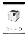
Advantage
Disc RepairMachine
Knowledge Resource
7307 South 89th Place
Mesa, Arizona 85212
480-827-8786
www.azuradisc.com
QUICK START
The Advantage • • • • • • • • • • • • • • • • • • • • • • • • • • • • • • •
WARNING!
VERIFY THAT ALL PACKING MATERIALS HAVE BEEN REMOVED BEFORE APPLYING POWER
TO THE ADVANTAGE.
Ver 1.0
08-02-2005
© 2003
Azuradisc ®
All rights reserved. Printed in the U.S.A.
Quick Start
TABLE OF CONTENTS
SAFETY ......................................................................................................................................................3
TRAINING OPTIONS ................................................................................................................................... 3
FACTORY TRAINING .......................................................................................................................3
ADDITIONAL TRAINING .................................................................................................................. 3
CONTACT US ............................................................................................................................................. 3
DISCLAIMER .............................................................................................................................................. 3
PART IDENTIFICATION ...............................................................................................................................4
PACKING MATERIAL IDENTIFICATION ....................................................................................................... 5
ADVANTAGE SET-UP ..................................................................................................................................6
REMOVE PACKING MATERIAL ........................................................................................................6
Load Chamber - Spindle Installation .....................................................................................6
Unload Chamber - Spindle Installation ................................................................................. 6
LOAD-SIDE / DISC SEPARATOR SPINDLE (DSS) ............................................................................ 7
SPINDLE ASSEMBLY AND INSTALLATION ...................................................................................... 7
PREPARE THE WATER TANK ..........................................................................................................8
PREPARE THE WATER PITCHER ....................................................................................................9
PREPARE THE POLISH RESERVOIR AND REACTOR CHAMBER .................................................... 9
ATTACH THE POLISH PADS .......................................................................................................... 10
INITIALIZE THE ADVANTAGE ........................................................................................................ 11
PRIME WATER AND POLISH HOSES .............................................................................................12
2
Ver 1.0
08-02-2005
Quick Start
SAFETY
Safety is the highest priority in the Azuradisc product line, and we have achieved safe designs with user-friendly
interfaces through extensive research and maximized use of technology for all of our machines. It is the operator’s responsibility to be familiar with the operation of the machine and routinely follow the maintenance instructions provided in this manual.
WARNING:
The Machine must be turned OFF for maintenance. Unless otherwise stated in this manual, all product maintenance instructions MUST be performed with the machine turned OFF and the power lead removed from the rear socket.
When using the Advantage disc repair machine, the following basic safety precautions should always be followed
to reduce the risk of fire, electric shock, and/or injury to persons:
•
Read this manual before assembling or using the machine.
•
Use this machine only for its intended use as described in this manual.
•
Use only with Azuradisc recommended accessories and repair materials. (The use of repair materials not
evaluated for use with this machine may damage discs permanently, cause injuries, and/or void the warranty.)
•
This machine is not intended for use by children or infirm persons.
•
Do not operate this machine if it has a damaged cord or plug, is not working properly, has been damaged,
or immersed in water. Return the machine to Azuradisc or authorized technician for examination, repair, or
adjustment.
•
To disconnect, turn off the machine, then remove plug from the electrical outlet.
•
When using an extension cord, use a grounded plug or socket to connect the machine.
•
Disconnect electrical supply before cleaning.
TRAINING OPTIONS
FACTORY TRAINING
Training sessions may be scheduled with a Factory Direct Representative by calling the corporate headquarters
Tech Services Department in the United States of America at 1.480.827.8786. For participation and availability
outside of the United States, please contact your local distributor.
ADDITIONAL TRAINING
Contact the local sales representative or distributor for participation pricing and availability of additional training
options.
CONTACT US
Corporate Headquarters:
United States of America
Azuradisc Corporate Headquarters
7307 South 89th Place
Mesa, Arizona 85212
www.azuradisc.com
Technical Support: 1.480.827.8786
Sales Inquires: 1.800.933.4923
Email: [email protected]
DISCLAIMER
© 2003 Azuradisc ® . All rights reserved. Printed in the U.S.A.
DISCLAIMER: This document provides information about the Azuradisc Advantage disc repair machine. All software included with the Advantage
is furnished under license and may not be used or copied except in accordance with the terms of the Software License Agreement herein. Except
as permitted by licensing. No part of this document may be reproduced, stored in a retrieval system, or transmitted, in any form or by any means,
electronic, mechanical, recording, or otherwise, without the express prior written permission of Azuradisc Incorporated. The examples provided in
this document are solely for illustrative purposes and may need to be modified to assure proper functioning on actual repair machine(s). Azuradisc
assumes no liability for damages incurred directly or indirectly from errors or omissions contained in this document, or discrepancies between the
product and this document. The content of this document is subject to change without notice.
All other product names or logos mentioned herein are the property of their respective companies. Reference herein to any specific commercial
firm, commercial product, process, or service by trade name, trademark, manufacturer, or otherwise, does not constitute or imply its endorsement,
recommendation, or favoring by Azuradisc or the individual employees of Azuradisc. For additional information, visit www.azuradisc.com.
3
Ver 1.0
08-02-2005
Quick Start
THE ADVANTAGE PART IDENTIFICATION
1
Operator Interface Touchscreen (OIT)
2
On/Off Button
3
Turret
4
Polish Head With Pads
2
20
1
5
Disc Turntable
6
Splash Guard
7
Disc Transfer Arm
8
9
3
Unload Chamber
(With Spindle Inside)
4
6
Load Chamber
(With Spindle Inside)
7
5
8
9
10
Polish Pump
14
10
11
Polish Reservoir
12
Water Pump
11
13
15
13
14
12
Filters 1 & 2
(Inside Water Pitcher)
17
Serial Number Label
(Inside Cabinet)
15
Water Recirculation System
16
Water Tank
16
18
19
17
Water Pitcher
18
Filter 3 (Inside Water Tank)
19
Caster Locks
20
Lock-Out/Maintenance Key
4
Ver 1.0
08-02-2005
Quick Start
THE ADVANTAGE PACKING MATERIALS IDENTIFICATION
1
Crate
2
ESD Safe Cover
3
Protective Foam
4
Instruction Kit / Start-up
5
Protective Foam
6
Protective Foam
7
Caution Labels
8
Manuals / Tool Kit
9
Gouge Kit:
3
1
4
2
5
• Polish Compound
• Micro-Abrasive Pads
• A&B Solution
7
6
8
9
5
Ver 1.0
08-02-2005
Quick Start
WARNING:
Verify that all packing materials have been removed before applying power to the Advantage.
SET UP
REMOVE PACKING MATERIAL
Plastic Lift
Touchscreen
Stylus
Tape
Reflective
Surface
(Load
Chamber Only)
Spindle
1. Remove Stylus from the Touchscreen
2. Verify the reflective surface is clean on the Load Chamber Lift Assembly.
3. Install the Spindles in the Load and Unload Chambers.
NOTE:
Pull out drawer on Load Side to install Spindle.
Load Chamber - Spindle Installation
Unload Chamber - Spindle Installation
4. Ensure that the Plastic Lift is properly installed (T-side up) on both Spindles.
6
Ver 1.0
08-02-2005
Quick Start
LOAD SIDE - Disc Separator Spindle (DSS)
Please Read Below Notice Prior to Initial Operation
DSS units shipped with a new machine have been factory calibrated for that particular repair machine,
and further calibration should not be necessary. If you have received a separate DSS, please refer to the
calibration instructions below to ensure optimum function in your disc repair machine.
Azuradisc has designed a spindle specifically for use on the load side of The Advantage & One Touch
Professional Disc Repair Machines to reduce the possibility of the machine picking up more than one disc at a
time. This condition can occur if the stacked discs adhere to one another for any number of reasons. Discs can
get stuck together because of soda, static cling, because they are damp or many other reasons. This new &
improved design is called the Disc Spindle Separator (DSS), it is designed to help seperate lightly stuck together
discs, however is not designed to pry apart discs that are seriously stuck together.
Your DSS has a RED MARK on it for Proper Alignment, be sure to line up the red line mark on the base of the
spindle with the red line mark on the spindle drawer.
SPINDLE ASSEMBLY AND INSTALLATION
The Disc Spindle Separator is made up of three pieces:
• Spindle base with an adjustable nut
• Spindle shaft
• Plastic lifting ring
Adjustable Nut
Step 1. Screw the shaft onto the threaded base. The adjustable nut is the white
nylon collar just below the shaft threads.
Step 2. Place the plastic lifting ring onto the shaft. The big end of the ring should
be towards the spindle end (like a T).
7
Ver 1.0
08-02-2005
Quick Start
Polish Reservoir
Water Pitcher
Tape
Water Tank
5. Remove the packing tape from the Polish Reservoir, Water Tank and Water Pitcher.
PREPARE WATER TANK
Quick Disconnect
Fitting
6. Add 1 entire bottle each of Solution A & B and fill Water Tank with water until Filter 3 is fully covered.
NOTE:
Gently stir the solution and water mixture to prevent undesirable repair marks on discs.
7. Verify the Water Intake hose is connected to Filter #3 and replace cover.
Water Intake
Hose
Water Tank
8. Place Water Tank in the bottom of the Advantage and verify the Water Intake Hose is secure in the quick disconnect fitting.
8
Ver 1.0
08-02-2005
Quick Start
PREPARE WATER PITCHER
Filter 1
Filter 2
Drain Tube
9. Verify that Filter 1 is inside Filter 2 and both filters are in the Water Pitcher.
10. Verify that Drain Tube is secure in the Water Tank Cover quick disconnect fitting.
PREPARE POLISH RESERVOIR AND REACTOR CHAMBER
11. Fill the Polish Reservoir and place in the holding tray.
9
Ver 1.0
08-02-2005
Quick Start
Retaining Clips
Drain Tube
Adapter
Align over
Filter #1
Reactor Chamber
(Aluminum
Coagulation Tube)
12. Verify the Reactor Chamber is in the retaining clips, the Chamber exit is over Filter #1, and the drain tube adapter is inserted into the top of the Aluminum Coagulation Tube with opening of drain tube adapter facing forward.
ATTACH POLISH PADS
13. Lift both Release Tabs and pull out
the Polishing Pad Turret Drawer.
14. Pull drawer out. Pull knob on left side of drawer out. While holding knob out,
slowly lift drawer up and rotate back. Release knob into place.
15. Ensure that the turret drawer knob is locked in place.
16. Place pads on heads according to
velcro color code. Ensure the pads
are centered on the heads.
Incorrect
Correct
17. Press pads firmly in place.
18. Pull drawer knob again to flip Turret back over and close drawer.
19. Ensure Drawer Latches are secure.
10
Ver 1.0
08-02-2005
Quick Start
NOTE:
If the Turret Drawer is pulled completely forward, lift the side latches to push Turret Drawer back in.
Side Latch (Both sides of drawers)
20. Lift side latches simultaneously and gently push until drawer moves. Then, grab the center of the drawer
and push into place and lock. Ensure that drawer cannot be pulled back out.
NOTE:
Refer to “Replacing Polish Pads” section of this manual if polish pads need to be removed for any reason.
INITIALIZE THE ADVANTAGE
WARNING:
Verify that all packing materials have been removed before applying power to the machine.
On/Off Button
Power Cord
System Initialization
21. Plug the machine into a correct electrical source.
22. Press the On/Off button to turn on.
23. Allow the software to initialize.
11
Ver 1.0
08-02-2005
Quick Start
NOTE:
The water and polish hoses must be primed prior to using for the first time.
PRIME WATER AND POLISH HOSES
Top Splash Cover
Paper
Towel
24. Select: Info on the OIT Main
Menu.
25. Place a cloth or paper towel on
the turntable (under the top splash
guard) to collect polish during hose
priming.
27. Run the Water Pump until all air
bubbles are gone from the
water hoses. Press OFF.
28. Run the Polish Pump until all air
bubbles are gone from the polish hoses. Press OFF.
26. Select: Water & Polish Prime.
12
Ver 1.0
08-02-2005
EDUCATION
The Advantage • • • • • • • • • • • • • • • • • • • • • • • • • • • • • • •
Ver 1.0
08-03-2005
© 2003 Azuradisc ® . All rights reserved. Printed in the U.S.A.
EDUCATION
TABLE OF CONTENTS
HOW DISCS ARE MADE ............................................................................................................................ 3
HOW A CD IS MADE ...................................................................................................................... 3
HOW A DVD IS MADE .................................................................................................................... 3
Single Layer DVDs ............................................................................................................. 4
Double Layered DVDs ........................................................................................................ 4
Double Sided DVDs ............................................................................................................ 4
Double Sided / Double Layered DVDs ................................................................................. 4
IDENTIFYING SCRATCHES ........................................................................................................................ 5
CDS,CD-ROMS & DVDS ................................................................................................................. 5
Reading Side Scratches ......................................................................................................5
CDS & CD-ROMS ONLY ................................................................................................................. 5
Top Side Scratches ............................................................................................................ 5
Top Side Foil Dents ............................................................................................................ 5
2
Ver 1.0
08-03-2005
EDUCATION
HOW DISCS ARE MADE
HOW A CD IS MADE
CDs consist of 99% clear polycarbonate plastic. The reflective layer, protective layer and screen print comprise
the remaining 1% of the disc.
1. A disc is created from molten polycarbonate
and digital information is stamped on the top
of the disc, while it is still near melting point,
using a die with microscopic bumps. These
bumps are known as “pits and lands”.
4
2. After the information is molded into the polycarbonate, a reflective foil layer is applied
using a process called sputtering or wet
silvering. This layer reflects the laser back to
the player, so it’s integrity is extremely
important. The layer is usually silver, but can
be made of gold or platinum.
3
2
1
3. A clear lacquer coating is applied to seal the
reflective layer and prevent oxidation. This
layer is very thin and offers little protection
from top side scratches.
4. Finally the artwork is screen-printed on the
top of the disc.
Pits and Lands are imprinted into the disc to indicate a one or a zero. A laser beam is sent from the player to the
disc and the reflective layer reflects it back to the reader and the ones and zeros are translated by the player.
Recordable discs have a photosensitive dye type layer instead of the stamped information layer. This layer, when
exposed to a certain light, will make an impression of a pit into the layer.
Label
Pit
Land
Reflective Layer
Laser
Polycarbonate
Re-recordable discs use a layer that allows the laser to polarize the photosensitive layer back and forth between
a visible pit to an invisible pit.
HOW A DVD IS MADE
DVDs are made in different ways depending on the amount of information that is recorded on the disc. DVDs may
be single or double layered and single or double layered double sided.
NOTE:
Due to the amount of information stored on DVD’s, the amount of polycarbonate is less than a normal CD; therefore a DVD can
not be repaired as many times as a CD.
3
Ver 1.0
08-03-2005
EDUCATION
Single Layer DVDs (DVD-5 - 4.7GB)
These DVDs are made the same way as a CD with one additional polycarbonate layer added between the label
and the pits and lands.
Thickness: 1.2mm
Label
0.6mm
Polycarbonate
0.6mm
Reflective Layer
Polycarbonate
Laser
Double Layered DVDs (DVD-9 - 8.5GB)
Double layered DVDs have a semi reflective layer and a reflective layer giving two layers to store information.
Thickness: 1.2mm
Label
Polycarbonate
0.6mm
Reflective Layer
Bonding Layer
Semi Reflective Layer
0.6mm
Polycarbonate
Laser
Double Sided DVDs (DVD-10 - 9.4GB)
Double sided DVDs consist of two discs bonded back to back with the reflective layers in the middle and both
sides are repairable. Double sided DVDs use a different size of micro-abrasive polishing papers to prevent the
manufacturer’s label area from being removed during the repair process.
Laser
Polycarbonate
Thickness: 1.2mm
0.6mm
Reflective Layer
Bonding Layer
Reflective Layer
0.6mm
Polycarbonate
Laser
Double Sided/Double Layered DVDs (DVD-18 - 17.1GB)
Double sided/double layered DVDs are simply two double layered discs bonded back to back.
Laser
Polycarbonate
Semi Reflective Layer
Thickness: 1.2mm
0.6mm
Reflective Layer
Bonding Layer
Reflective Layer
0.6mm
Semi Reflective Layer
Polycarbonate
Laser
4
Ver 1.0
08-03-2005
EDUCATION
IDENTIFYING SCRATCHES
The three basic types of scratches are topside, reading side, and the top side foil dent. When repairing DVDs the
top side scratch and the foil dent do not apply due to the construction of the disc.
Scratch
Reflection
CDs, CD-ROMs & DVDs
Reading Side Scratches
Reading side scratches are the most common type, the easiest to identify, and the only type of scratch that can
be repaired.
If the scratch has a double Image, as shown in the figure to the right, it is a reading side scratch and can be
repaired by using an Azuradisc scratch repair machine. The double image is the result of the actual scratch and
a reflection made by the reflective foil layer.
Light passes
through the disc.
CDs & CD-ROMs ONLY
The scratches shown are
not found on DVDs
Top Side Scratches
Top side scratches are caused by a sharp object damaging the printed label of a disc. In this case, the information just below the printed label is damaged and causes a skip. Top side scratches cannot be repaired, however
they can be prevented by using an Azuradisc Scratch Guard.
The easiest way to identify the top side scratch is to hold the suspected scratch up to a light source and the light
will pass through the disc.
NOTE:
If light does not pass through, check the reading side of the disc and if there is a scratch without a “double image”, it
is a top side scratch that did not remove any of the label.
No double image
Top Side Foil Dents
Top side foil dents are not scratches but look like a scratch on the reading side of the disc. The dent is made by
a large amount of pressure put on the label side of the disc, causing the foil layer to dent. This dent will cause
skips and cannot be repaired, however they can be prevented using an Azuradisc Scratch Guard.
The easiest way to identify the top side foil dent is to see if there is a “double image” produced. There should not
be a second image because the damage is to the inner foil layer. There will not be any evidence on the label side
of the disc because the pressure did not cause any of the label to be removed.
5
Ver 1.0
08-03-2005
OPERATION & TROUBLESHOOTING
The Advantage • • • • • • • • • • • • • • • • • • • • • • • • • • • • • • •
WARNING!
VERIFY THAT ALL PACKING MATERIALS HAVE BEEN REMOVED BEFORE APPLYING POWER
TO THE ADVANTAGE.
Ver 1.0
08-03-2005
© 2003
Azuradisc ®
All rights reserved. Printed in the U.S.A.
OPERATION & TROUBLESHOOTING
TABLE OF CONTENTS
SAFETY ......................................................................................................................................................3
TRAINING OPTIONS ................................................................................................................................... 3
FACTORY TRAINING .......................................................................................................................3
ADDITIONAL TRAINING .................................................................................................................. 3
CONTACT US ............................................................................................................................................. 3
DISCLAIMER .............................................................................................................................................. 3
PART IDENTIFICATION .............................................................................................................................. 4
PRE-OPERATION CHECK ........................................................................................................................... 5
NORMAL OPERATION ................................................................................................................................ 5
MAIN MENU SCREEN ..................................................................................................................... 5
CD & DVD Menus ................................................................................................................6
Clean / Repair Menu ............................................................................................................6
GAME DISC SCREENS ................................................................................................................... 7
Game Disc Screen 1 ........................................................................................................... 7
Game Disc Screen 2 ........................................................................................................... 7
INFO MENU ................................................................................................................................................8
ADVANCED OPERATIONS ..........................................................................................................................9
LOGIN SCREEN ............................................................................................................................. 9
TECHNICIAN MODE ......................................................................................................................10
2
Ver 1.0
08-03-2005
OPERATION & TROUBLESHOOTING
SAFETY
Safety is the highest priority in the Azuradisc product line, and we have achieved safe designs with user-friendly
interfaces through extensive research and maximized use of technology for all of our machines. It is the operator’s responsibility to be familiar with the operation of the machine and routinely follow the maintenance instructions provided in this manual.
WARNING:
The Machine must be turned OFF for maintenance. Unless otherwise stated in this manual, all product maintenance instructions MUST be performed with the machine turned OFF and the power lead removed from the rear socket.
When using the Advantage disc repair machine, the following basic safety precautions should always be followed
to reduce the risk of fire, electric shock, and/or injury to persons:
•
Read this manual before assembling or using the machine.
•
Use this machine only for its intended use as described in this manual.
•
Use only with Azuradisc recommended accessories and repair materials. (The use of repair materials not
evaluated for use with this machine may damage discs permanently, cause injuries, and/or void the warranty.)
•
This machine is not intended for use by children or infirm persons.
•
Do not operate this machine if it has a damaged cord or plug, is not working properly, has been damaged,
or immersed in water. Return the machine to Azuradisc or authorized technician for examination, repair, or
adjustment.
•
To disconnect, turn off the machine, then remove plug from the electrical outlet.
•
When using an extension cord, use a grounded plug or socket to connect the machine.
•
Disconnect electrical supply before cleaning.
TRAINING OPTIONS
FACTORY TRAINING
Training sessions may be scheduled with a Factory Direct Representative by calling the corporate headquarters
Tech Services Department in the United States of America at 1.480.827.8786. For participation and availability
outside of the United States, please contact your local distributor.
ADDITIONAL TRAINING
Contact the local sales representative or distributor for participation pricing and availability of additional training
options.
CONTACT US
Corporate Headquarters:
United States of America
Azuradisc Corporate Headquarters
2885 N. Nevada St. Suite #140
Chandler AZ, 85225
www.azuradisc.com
Technical Support: 1.480.827.8786
Sales Inquires: 1.800.933.4923
Email: [email protected]
Azuradisc South Pacific Headquarters
New Zealand
Gateway Park, Unit 5
59 Paul Matthews Road
North Harbour, Auckland 3013
New Zealand
POSTAL ADDRESS
P.O. Box 303-352
North Harbour, Auckland 3013
New Zealand
Telephone: +64.9.414.1430
Email: [email protected]
Azuradisc Australia
Telephone: 1.300.360.565
Fax: 1.300.360.144
Email: [email protected]
DISCLAIMER
© 2003 Azuradisc ® . All rights reserved. Printed in the U.S.A.
DISCLAIMER: This document provides information about the Azuradisc Advantage disc repair machine. All software included with the Advantage
is furnished under license and may not be used or copied except in accordance with the terms of the Software License Agreement herein. Except
as permitted by licensing. No part of this document may be reproduced, stored in a retrieval system, or transmitted, in any form or by any means,
electronic, mechanical, recording, or otherwise, without the express prior written permission of Azuradisc Incorporated. The examples provided in
this document are solely for illustrative purposes and may need to be modified to assure proper functioning on actual repair machine(s). Azuradisc
assumes no liability for damages incurred directly or indirectly from errors or omissions contained in this document, or discrepancies between the
product and this document. The content of this document is subject to change without notice.
All other product names or logos mentioned herein are the property of their respective companies. Reference herein to any specific commercial
firm, commercial product, process, or service by trade name, trademark, manufacturer, or otherwise, does not constitute or imply its endorsement,
recommendation, or favoring by Azuradisc or the individual employees of Azuradisc. For additional information, visit www.azuradisc.com.
3
Ver 1.0
08-03-2005
OPERATION & TROUBLESHOOTING
THE ADVANTAGE PART IDENTIFICATION
1
Operator Interface Touchscreen (OIT)
2
On/Off Button
3
Turret
4
Polish Head With Pads
2
20
1
5
Disc Turntable
6
Splash Guard
7
Disc Transfer Arm
8
Unload Chamber
(With Spindle Inside)
3
9
4
6
7
5
Load Chamber
(With Spindle Inside)
8
9
10
Polish Pump
14
10
11
Polish Reservoir
12
Water Pump
11
13
15
13
14
12
Filters 1 & 2
(Inside Water Pitcher)
17
Serial Number Label
(Inside Cabinet)
15
Water Recirculation System
16
Water Tank
16
18
19
17
Water Pitcher
18
Filter 3 (Inside Water Tank)
19
Caster Locks
20
Lock-Out/Maintenance Key
4
Ver 1.0
08-03-2005
OPERATION & TROUBLESHOOTING
PRE-OPERATION CHECK
For optimum performance of your machine, check the following items before each use:
1.
Verify the machine is located on a stable level surface and the casters are locked to prevent it from rolling
around.
2.
Connect the machine to a standard electrical source.
3.
Polish Pads are installed on the Turret.
4.
Drain from Lower Splash Guard to Reactor Chamber is clear.
5.
Premixed water level is between minimum and maximum fill lines.
6.
Water & Polish Tubing have no air bubbles.
7.
Polish is present in the reservoir.
NORMAL OPERATION
NOTE:
Selecting the Azuradisc Logo will return the screen to the Main Menu from any other screen. The Stylus may be used to make
selections on the OIT.
MAIN MENU SCREEN
Figure 1 - Main Menu
Definition
Selection
AZURADISC LOGO
Returns to Main Screen
RESET
Clears all previous selections and returns all machine functions
to home positions.
LOAD
Load discs before, during, or after the repair process.
INFO
Info screen to access supply levels, usage statistics, and other
features.
LOGIN
Accesses advanced user levels and maintenance tools.
CD
DVD
Recipes designed for clear-type discs such as music and data
discs.
Recipes designed for high-density and multi-layered discs such
as movie discs.
GD
Recipes designed for different game-type discs.
CUSTOM
Custom recipes (currently reserved for future use).
1.
Press the On/Off Switch on the top right side of the machine and wait for it to initialize.
2.
Verify the type and condition of the Polish Pads.
3.
Ensure there is an adequate supply of Polish and water.
4.
Sort the discs to be repaired by type (i.e. Music CDs, DVDs or Game Discs.)
5
Ver 1.0
08-03-2005
OPERATION & TROUBLESHOOTING
NOTE:
Only one type of disc may be repaired in a session and discs must be clean and dry.
5.
Discs are sorted by the type of repair or cleaning needed (i.e. gouged, scratched, clean etc.).
6.
Press Load on the Operator Interface Touchscreen (OIT), open the door on the Load Chamber and place
the discs on the spindle with the disc labels facing down.
NOTE:
Discs must be loaded with the labels facing down!
7.
Close the Load Chamber door and select the type of disc to be repaired on the OIT.
8.
Select the level of cleaning or repair required on the OIT.
9.
Press Start on the OIT to begin the process.
CD & DVD MENUS
1.
Sort the discs to be repaired by type (i.e. Music CDs, DVDs or Game Discs).
NOTE:
Only one type of disc may be repaired in a session and discs must be clean and dry.
2.
Sort discs by the type of repair needed (i.e. gouged, deep scratches, clean etc.).
3.
Press Load on the OIT, open the door on the Load Chamber and place the discs on the spindle with the
disc labels facing down.
NOTE:
Discs must be loaded with the labels facing down!
4.
Close the Load Chamber door and select CD or DVD on the OIT.
5.
Select the level of cleaning or repair required on the OIT.
6.
Press Start on the OIT to begin the process.
CLEAN - REPAIR MENU
Figure 2 - Clean/Repair - Menu
Selection
Definition
GOUGE
For repairing extremely deep scratches or gouges.
DEEP
For repairing deeply scratched discs.
MEDIUM
For repairing average-depth scratched discs.
AVERAGE
For repairing lightly scratched discs.
LIGHT
For polishing lightly scuffed and scratched discs.
POLISH
For cleaning discs with fingerprints, dust, dirt, or oil.
6
Ver 1.0
08-03-2005
OPERATION & TROUBLESHOOTING
GAME DISC SCREENS
1.
Sort the discs to be repaired by type (i.e. Music CDs, DVDs or Game Discs).
2.
Sort discs by the type of repair needed (i.e. gouged, deep scratches, clean etc.)
3.
Press Load on the Touch Screen, open the door on the Load Chamber and place the discs on the spindle with the disc labels facing down.
4.
Close the Load Chamber door and select the type of game (i.e. PlayStation ®1, Playstation ®2, Xbox or
GameCube TM ) on the OIT.
NOTE:
An adapter for the Disc Turntable is required for repairing or cleaning Game Cube discs.
GAME DISC SCREEN 1
Figure 3 - Game Menu #1
Selection
Definition
PS 1
Selects PlayStation®1 type discs.
PS 2
Selects Playstation®2 type discs.
Xbox
Selects Xbox type discs.
Game Cube
Selects Game Cube® type discs (Note: Turntable Adapter Required).
GAME DISC SCREEN 2
5.Select the level of cleaning or repair required on the Touch Screen
Figure 4 - Game Disc Menu #2
Selection
6.
Definition
GOUGE
For repairing extremely deep scratches or gouges.
DEEP
For repairing deeply scratched discs.
MEDIUM
For repairing average-depth scratched discs.
AVERAGE
For repairing lightly scratched discs.
LIGHT
For polishing lightly scuffed and scratched discs.
POLISH
For cleaning discs with fingerprints, dust, dirt, or oil.
Press Start on the OIT to begin the process
7
Ver 1.0
08-03-2005
OPERATION & TROUBLESHOOTING
DISC REPAIR PROGRESS SCREEN
Selection
Definition
COMPLETE DISC THEN STOP
Completes current disc repair & ends process
ABORT
Aborts process to allow operator to check for problem
to reset system. You must power off and on the
machine
8
Ver 1.0
08-03-2005
OPERATION & TROUBLESHOOTING
INFO MENU
Figure 5 - Info Menu
Definition
Selection
POLISH PAD STATUS
Allows the polish pad timers to be reset.
LIQUID SYSTEM STATUS
Allows the liquid system timers (water, polish, filters, and
Aluminum Tube) to be reset.
RECIPE STATISTICS
Displays recipe statistics and tracking; allows resetting counters.
GAME DISC RECIPE
STATISTICS
Displays recipe statistics and tracking for game discs; allows
resetting counters.
COMPONENT RUN TIME Tracks component run time.
Allows manual operation of water and polish pumps to prime sysWATER & POLISH PRIME
tems.
Shows status of disc spindles, disc count position and door senSENSOR TEST
sors.
MAIN
POLISH PAD STATUS
GAME DISC RECIPE STATISTICS
Returns to Main Menu.
LIQUID SYSTEM STATUS
RECIPE STATISTICS
COMPONENT RUN TIME
WATER & POLISH PRIME
SENSOR TEST
9
Ver 1.0
08-03-2005
OPERATION & TROUBLESHOOTING
ADVANCED OPERATIONS
LOGIN SCREEN
Figure 6 - Login Screen
Selection
Definition
USER MODE
No password required.
ADVANCED
OPERATION
Access additional user levels and maintenance tools
(Password: 741852).
ADVANCED OPERATIONS
MANUAL OPERATIONS
DISC TURNTABLE
LOAD / UNLOAD
POLISH PAD MOTOR
TURRET
TURNTABLE LIFT
WATER & POLISH PUMPS
WATER RECYCLE
10
Ver 1.0
08-03-2005
OPERATION & TROUBLESHOOTING
DISC TRANSFER
TECHNICIAN MODE
Figure 7 - Login Screen
Selection
Definition
USER MODE
No password required.
TECHNICIAN
MODE
To be used by advanced users only
(Password: 753951).
MAIN TECHNICIAN MENU
MAIN CALIBRATION MENU
DISC TRANSFER
CALIBRATION
LOAD ELEVATOR
CALIBRATION
TURNTABLE LIFT
CALIBRATION
TURRET CALIBRATION
11
Ver 1.0
08-03-2005
OPERATION & TROUBLESHOOTING
FORCE ADJUST SETUP
PROGRAM UPDATE
MAIN MENU
PROGRAM UPDATE
12
Ver 1.0
08-03-2005
Advantage
TROUBLESHOOTING GUIDE
PROBLEM
Abrasive and/or polish pads
torn, off leaving adhesive on
discs
AREA
SEVERITY OF
CONSEQUENCES POSSIBLE CAUSE(S)
Finish
High
Turntable not spinning
Concentric circular marks on
disc
Finish
High
Sanding pads not spinning
Deep round marks on Disc
Finish
High
Turntable not spinning
Drips on finished discs
Finish
Low
Liquid build-up in splash cover
Hazy Discs
Finish
Low
Insufficient Polish
Hazy Discs
Finish
Low
Insufficient Pressure
Hazy Discs
Finish
Low
Change Turntable force to
see if finish improves
Compare black velcro on
pads- F pads have straight
Using OT50 Stage 2 pad instead rows, OT50 pads have
random velcro
Replace with correct F pads
of OTPro F Pad
Pitted Discs
Repair marks near stacking
ring
Finish
Medium
Insufficient Water Flow
Finish
Error
Message
Low
Abrasive pad off-center
Low
DSS Set too high
Prime pump and observe
water flow
power off OTP and visually
inspect pads
Manual Operations- Disc
Transfer
Low
Black plastic lift ring is under the
load elevator
All three suction cups not
contacting the disc due to loose
elevator screws
Visual Inspection
Move the elevator fork by
hand to check for loose
screws
Medium
Vacuum switch set incorrectly
"Dropped Disc" Error
"Failed to Home Load
Error
Elevator" message on start-up Message
"Failed to Pick Up Disc" Error
Error
Message
Load Elevator over-running top Load
of tower during calibration
Chamber
Unpleasant odor
White sediment in Water
Reservoir
Medium
Recirculation
System
Low
Recirculation
System
Low
Bacterial growth in water
reservoir
Coagulation tube not working
correctly
CONFIRMATION
SOLUTION
Reboot machine and check Shut down and re-insert turntable
turntable station-holding
drawer
Manual Operations- run
sanding motor while
observing pads
Reboot machine and check
turntable station-holding
White drips on discs on
Unload Spindle
Prime pump and observe
polish flow
Shut down and re-insert turntable
drawer
Clean upper splash cover with
damp cloth
Check hose connections, replace
pump tube
Increase Turntable Force
Adjustment in 1 step increments
until finish improves
Reconnect all Quick-Disconnects,
Replace pump tube
CALIBRATION
PROCEDURE
Preflight Checklist
Preflight Checklist
NA
Prime Water and Polish
Turntable Force Adjustment
NA
Prime Water and Polish
Re-center abrasive pads in holders NA
Calibrate DSS
DSS Setup
Pull out load spindle drawer and reboot; elevator should home
normally
NA
Disassemble track and tighten
screws, re-assemble with Loctite
Push "Mode" on Vacuum
Use the up and down arrows to
guage, P1should read -7.00 adjust P1 to -7.00
Thoroughly clean reservoir, filters
and flush water lines. Refill with
water + A&B solutions and prime
water lines
Open water reservoir lid
No "Cottage Cheese"
Replace Al pipe, verify voltage
appearance in filter 1
between Al pipe and outer tube
Load Elevator Calibration
NA
Prime Water and Polish
NA
White sediment in Water
Reservoir
"Failed to Pick Up Disc" Error
Recirculation
System
Low
Error
Message
Low
Error
Message
Low
Hole in filters 1 or 2
Fluid hoses contacting disc
during transfer
Transfer arm suction cups not
centered over disc
Damaged Discs
Repair
Chamber
High
Disc caught between upper and
lower splash housings
Damaged Discs
Repair
Chamber
High
Two discs being repaired at the
same time
High
Insufficient Water Flow
High
Low
Too much repair pressure
Polish Shaft gear or drive gear
worn or broken
Polish Shaft gear to drive gear
out of tolerance
"Dropped Disc" Error
Noise- grinding during repairs
Noise- grinding during repairs
Noise- whining during repairs
Repair
Chamber
Repair
Chamber
Repair
Chamber
Noise- whining during repairs
Low
False Error messages
displayed
Touch
Screen
Low
Incorrect com cable between
Touch Screen and Control
Boards
Freeze at "Loading Please
Wait"
Touch
Screen
Low
Com cable disconnected
Partial blackout of Touch
Screen
"Failed to Home Turntable"
message on start-up
Touch
Screen
Turntable
Drawer
Turntable not spinning
Turntable
Drawer
Turntable not spinning
Turntable not spinning
Turntable not spinning
"Failed to Home Turret"
message on start-up
Turntable
Drawer
Turntable
Drawer
Turntable
Drawer
Turret
Drawer
Load Elevator not raising when
start button is pressed and
giving a very low or high disc Load
count
Chamber
Low
Touch Screen retaining screws
too tight
Turntable Drawer not properly
seated
High
Bad control board output
High
Bad Turntable motor encoder
Broken or Loose Turntable
Coupler
Low
High
High
Low
High
Remove filters 1 and 2 and
wash out, looking for leaks
Manual Operations- Disc
Transfer
Manual OperationsTransfer Arm Test
Replace leaking filter
Secure Fluid hoses with Zip Ties
clear of disc path
Calibrate transfer arm
Check the chamber for
Open Main door and check obstructions that knock the disc
turntable during process
from the transfer arm
Open Main door and check
turntable during process
Finished discs are very
warm and possibly pitted,
bubbles in water line
Finished discs are very
warm
Visually inspect gears using
Turret Test
Visually inspect gears using
Turret Test
Occasional Dropped Disc
and Failed to Pick Up Disc
errors on screen, but
machine continues to
operate correctly.
Visually check cable at
Touch Screen and Control
Board
NA
NA
Transfer Arm Calibration
Manual Operations, Transfer
Arm Test
Adjust DSS to prevent double disc
pickup
DSS Setup
Reconnect all Quick-Disconnects,
Replace pump tube
Prime Water and Polish
Decrease turntable force
Turntable Force Adjustment
Replace worn or broken gears
Turret Calibration
Calibrate Turret
Turret Calibration
Replace Com cable
NA
Re-connect cable
NA
Motor wires disconnected
Turret Drawer not properly
seated
Screws should be installed Remove and re-install screws
finger-tight with Loctite
finger tight with Loctite
Power off OTP and re-seat
Re-seat drawer
Turntable Drawer
Coupler ok, No position
reporting in Motor Position
screen
Replace encoder
Coupler ok, No position
reporting in Motor Position
screen
Replace encoder
If turntable spins but motor
shaft does not spin
replace or tighten coupler
Visually confirm wires
connected to motor
Re-connect motor
Power off OTP and re-seat Turret
Re-seat drawer
Drawer
Slit mask has moved over the
disc present sensor.
When the start button is
pressed the load elevator
does not come up and the
disc count is verry large.
Also durring the calibration,
the first ten discs do not
move and the pro instantly
asks to put the one disc on
the elevator. The one disc
moves up slowly to meet
the suction cups.
Remove the slip mask
NA
NA
Manual ops, Motor Position
Manual ops, Motor Position
Manual ops, turntable
Manual ops, turntable
NA
NA
Advantage
TROUBLESHOOTING GUIDE
PROBLEM
Abrasive and/or polish pads
torn, off leaving adhesive on
discs
AREA
SEVERITY OF
CONSEQUENCES POSSIBLE CAUSE(S)
Finish
High
Turntable not spinning
Concentric circular marks on
disc
Finish
High
Sanding pads not spinning
Deep round marks on Disc
Finish
High
Turntable not spinning
Drips on finished discs
Finish
Low
Liquid build-up in splash cover
Hazy Discs
Finish
Low
Insufficient Polish
Hazy Discs
Finish
Low
Insufficient Pressure
Hazy Discs
Finish
Low
Change Turntable force to
see if finish improves
Compare black velcro on
pads- F pads have straight
Using OT50 Stage 2 pad instead rows, OT50 pads have
random velcro
Replace with correct F pads
of OTPro F Pad
Pitted Discs
Repair marks near stacking
ring
Finish
Medium
Insufficient Water Flow
Finish
Error
Message
Low
Abrasive pad off-center
Low
DSS Set too high
Prime pump and observe
water flow
power off OTP and visually
inspect pads
Manual Operations- Disc
Transfer
Black plastic lift ring is under the
load elevator
All three suction cups not
contacting the disc due to loose
elevator screws
Visual Inspection
Move the elevator fork by
hand to check for loose
screws
"Dropped Disc" Error
"Failed to Home Load
Error
Elevator" message on start-up Message
"Failed to Pick Up Disc" Error
Error
Message
Medium
Low
CONFIRMATION
SOLUTION
Reboot machine and check Shut down and re-insert turntable
turntable station-holding
drawer
Manual Operations- run
sanding motor while
observing pads
Reboot machine and check
turntable station-holding
White drips on discs on
Unload Spindle
Prime pump and observe
polish flow
Shut down and re-insert turntable
drawer
Clean upper splash cover with
damp cloth
Check hose connections, replace
pump tube
Increase Turntable Force
Adjustment in 1 step increments
until finish improves
Reconnect all Quick-Disconnects,
Replace pump tube
CALIBRATION
PROCEDURE
Preflight Checklist
Preflight Checklist
NA
Prime Water and Polish
Turntable Force Adjustment
NA
Prime Water and Polish
Re-center abrasive pads in holders NA
Calibrate DSS
DSS Setup
Pull out load spindle drawer and reboot; elevator should home
normally
NA
Disassemble track and tighten
screws, re-assemble with Loctite
Load Elevator Calibration
Advantage
TROUBLESHOOTING GUIDE
PROBLEM
Abrasive and/or polish pads
torn, off leaving adhesive on
discs
AREA
SEVERITY OF
CONSEQUENCES POSSIBLE CAUSE(S)
Finish
High
Turntable not spinning
Concentric circular marks on
disc
Finish
High
Sanding pads not spinning
Deep round marks on Disc
Finish
High
Turntable not spinning
Drips on finished discs
Finish
Low
Liquid build-up in splash cover
Hazy Discs
Finish
Low
Insufficient Polish
Hazy Discs
Finish
Low
Insufficient Pressure
Hazy Discs
Finish
Low
Change Turntable force to
see if finish improves
Compare black velcro on
pads- F pads have straight
Using OT50 Stage 2 pad instead rows, OT50 pads have
random velcro
Replace with correct F pads
of OTPro F Pad
Pitted Discs
Finish
Medium
Insufficient Water Flow
CONFIRMATION
SOLUTION
Reboot machine and check Shut down and re-insert turntable
turntable station-holding
drawer
Manual Operations- run
sanding motor while
observing pads
Reboot machine and check
turntable station-holding
White drips on discs on
Unload Spindle
Prime pump and observe
polish flow
Prime pump and observe
water flow
Shut down and re-insert turntable
drawer
Clean upper splash cover with
damp cloth
Check hose connections, replace
pump tube
Increase Turntable Force
Adjustment in 1 step increments
until finish improves
Reconnect all Quick-Disconnects,
Replace pump tube
CALIBRATION
PROCEDURE
Preflight Checklist
Preflight Checklist
NA
Prime Water and Polish
Turntable Force Adjustment
NA
Prime Water and Polish
PREVENTIVE MAINTENANCE
The Advantage • • • • • • • • • • • • • • • • • • • • • • • • • • • • • • •
Ver 1.0
08-04-2005
© 2003
Azuradisc ®
All rights reserved. Printed in the U.S.A.
PREVENTIVE MAINTENANCE
TABLE OF CONTENTS
SAFETY ......................................................................................................................................................3
TRAINING OPTIONS ................................................................................................................................... 3
FACTORY TRAINING .......................................................................................................................3
ADDITIONAL TRAINING .................................................................................................................. 3
CONTACT US ............................................................................................................................................. 3
DISCLAIMER .............................................................................................................................................. 3
PART IDENTIFICATION ...............................................................................................................................4
INTRODUCTION ......................................................................................................................................... 5
PRE-START CHECKLIST ............................................................................................................................ 5
MAINTENANCE REQUIREMENTS ............................................................................................................... 6
MAINTENANCE SCHEDULE ....................................................................................................................... 7
MAINTENANCE & SUPPLY ITEM USAGE CHART ............................................................................ 8
TURRET INSPECTION & MAINTENANCE ................................................................................................... 9
GENERAL ....................................................................................................................................... 9
CHECK & CLEAN TURRET & TOP SPLASH COVER ........................................................................ 9
REPLACING POLISH PADS ........................................................................................................... 10
REPLACING POLISH HEADS ........................................................................................................ 11
REPLACING POLISH HEAD GEARS .............................................................................................. 12
DISC TURNTABLE ................................................................................................................................... 13
WATER RECIRCULATION SYSTEM .......................................................................................................... 13
REACTOR CHAMBER ................................................................................................................... 14
WATER SYSTEM FILTERS ............................................................................................................ 15
To Service Filters 1&2 ....................................................................................................... 15
To Service Filter 3 ............................................................................................................. 15
ADVANTAGE COMPONENT LABELS ........................................................................................................ 16
LABEL SAMPLES .......................................................................................................................... 17
2
Ver 1.0
08-04-2005
PREVENTIVE MAINTENANCE
SAFETY
Safety is the highest priority in the Azuradisc product line, and we have achieved safe designs with user-friendly
interfaces through extensive research and maximized use of technology for all of our machines. It is the operator’s responsibility to be familiar with the operation of the machine and routinely follow the maintenance instructions provided in this manual.
WARNING:
The Machine must be turned OFF for maintenance. Unless otherwise stated in this manual, all product maintenance instructions MUST be performed with the machine turned OFF and the power lead removed from the rear socket.
When using the Advantage disc repair machine, the following basic safety precautions should always be followed
to reduce the risk of fire, electric shock, and/or injury to persons:
•
Read this manual before assembling or using the machine.
•
Use this machine only for its intended use as described in this manual.
•
Use only with Azuradisc recommended accessories and repair materials. (The use of repair materials not
evaluated for use with this machine may damage discs permanently, cause injuries, and/or void the warranty.)
•
This machine is not intended for use by children or infirm persons.
•
Do not operate this machine if it has a damaged cord or plug, is not working properly, has been damaged,
or immersed in water. Return the machine to Azuradisc or authorized technician for examination, repair, or
adjustment.
•
To disconnect, turn off the machine, then remove plug from the electrical outlet.
•
When using an extension cord, use a grounded plug or socket to connect the machine.
•
Disconnect electrical supply before cleaning.
TRAINING OPTIONS
FACTORY TRAINING
Training sessions may be scheduled with a Factory Direct Representative by calling the corporate headquarters
Tech Services Department in the United States of America at 1.480.827.8786. For participation and availability
outside of the United States, please contact your local distributor.
ADDITIONAL TRAINING
Contact the local sales representative or distributor for participation pricing and availability of additional training
options.
CONTACT US
Corporate Headquarters:
United States of America
Azuradisc Corporate Headquarters
2885 N. Nevada St. Suite #140
Chandler AZ, 85225
www.azuradisc.com
Technical Support: 1.480.827.8786
Sales Inquires: 1.800.933.4923
Email: [email protected]
Azuradisc South Pacific Headquarters
New Zealand
Gateway Park, Unit 5
59 Paul Matthews Road
North Harbour, Auckland 3013
New Zealand
POSTAL ADDRESS
P.O. Box 303-352
North Harbour, Auckland 3013
New Zealand
Telephone: +64.9.414.1430
Email: [email protected]
Azuradisc Australia
Telephone: 1.300.360.565
Fax: 1.300.360.144
Email: [email protected]
DISCLAIMER
© 2003 Azuradisc ® . All rights reserved. Printed in the U.S.A.
DISCLAIMER: This document provides information about the Azuradisc Advantage disc repair machine. All software included with the Advantage
is furnished under license and may not be used or copied except in accordance with the terms of the Software License Agreement herein. Except
as permitted by licensing. No part of this document may be reproduced, stored in a retrieval system, or transmitted, in any form or by any means,
electronic, mechanical, recording, or otherwise, without the express prior written permission of Azuradisc Incorporated. The examples provided in
this document are solely for illustrative purposes and may need to be modified to assure proper functioning on actual repair machine(s). Azuradisc
assumes no liability for damages incurred directly or indirectly from errors or omissions contained in this document, or discrepancies between the
product and this document. The content of this document is subject to change without notice.
All other product names or logos mentioned herein are the property of their respective companies. Reference herein to any specific commercial
firm, commercial product, process, or service by trade name, trademark, manufacturer, or otherwise, does not constitute or imply its endorsement,
recommendation, or favoring by Azuradisc or the individual employees of Azuradisc. For additional information, visit www.azuradisc.com.
3
Ver 1.0
08-04-2005
PREVENTIVE MAINTENANCE
THE ADVANTAGE PART IDENTIFICATION
1
Operator Interface Touchscreen (OIT)
2
On/Off Button
3
Turret
4
Polish Head With Pads
5
Disc Turntable
6
Splash Guard
7
Disc Transfer Arm
2
20
1
8
9
3
Unload Chamber
(With Spindle Inside)
4
6
Load Chamber
(With Spindle Inside)
7
5
8
9
10
Polish Pump
14
10
11
Polish Reservoir
12
Water Pump
11
13
15
13
14
12
Filters 1 & 2
(Inside Water Pitcher)
17
Serial Number Label
(Inside Cabinet)
15
Water Recirculation System
16
Water Tank
16
18
19
17
Water Pitcher
18
Filter 3 (Inside Water Tank)
19
Caster Locks
20
Lock-Out/Maintenance Key
4
Ver 1.0
08-04-2005
PREVENTIVE MAINTENANCE
INTRODUCTION
This guide provides specific maintenance instructions and schedule requirements for the Advantage Disc Repair
Machine. To ensure optimal performance, maximize supply usage, and minimize errors during operation:
•
Replace supply items when indicated by the Operator Interface Touchscreen (OIT)
•
Regularly perform the maintenance procedures in this manual.
WARNING:
Unless otherwise stated in this manual, all product maintenance instructions MUST be performed with the machineturned OFF
and the power cord removed from the rear socket.
PRE-START CHECKLIST
After performing maintenance procedures, ensure all of the following items are complete before initializing the
machine for use:
•
All Polish Pads are fitted to the Polish Heads Properly.
Polish Pad Drawer
Disc Turntable Drawer
•
Polish Pad Drawer is fully inserted and locked into position. If you pull on the drawer it shouldn’t budge.
•
Disc Turntable Drawer is correctly locked in position. If you pull on the drawer it shouldn’t budge.
•
Reactor Chamber is installed correctly with exit feeding into the first filter in the water pitcher.
5
Ver 1.0
08-04-2005
PREVENTIVE MAINTENANCE
•
Waste Water is feeding properly into the Aluminum Coagulation Tube.
•
Water level is correct and filters are in place.
•
A&B Solution has been added to the water, and the water pumps have been primed and do not contain air
pockets or air bubbles.
•
Polish bottle is full and system is primed, insure no air bubbles or air pockets are in the feed lines.
If all items have been checked and are correct, turn the machine on and allow it to initialize.
MAINTENANCE REQUIREMENTS
The following items are required to perform the maintenance procedures for the Advantage Disc Repair Machine:
1
For detailed knowledge and understanding the operation instructions, refer to:
- Quick Start Manual or
- Operation Manual.
2.
Basic understanding of the various names and positions of the parts of the machine; refer to the Part
Identification section of this manual.
3.
Knowledge of the procedures required to access the various parts.
The following tools are required to complete instructions in this manual:
10 mm Bottle Brush
Advantage Maintenance Kit:
(actual contents may vary from photo)
1 - #0 Phillips Screwdriver
1 - #2 Phillips Screwdriver
1 - #3 Slotted Driver
4 - Fluran Tubing 5”x5”
2 - Small Suction Cups
1 - 5.5 Amp Fuse
1 - Elbow
3 - V-Seals for Dongle
15 - E-Clips 3/32 (Retaining Clips)
6
Ver 1.0
08-04-2005
PREVENTIVE MAINTENANCE
30 - Polish Head Springs
1 - Flash Card Reader
6 - Small Head Gears
1 - Large Head Gear
30 - Zip Ties
2 - Zip Tie Holders
1 - Red Coupling Platen Shaft
2 - Bearings
1 - Gray Coupling
1 - Crescent Wrench
1 - Disc Turntable Pad
1 - Loctite
1 - .050 Allen Wrench
1 - 5/64 Allen Wrench
1 - 3/32 Allen Wrench
MAINTENANCE SCHEDULE
There are the two maintenance schedules (based on a “medium” repair selection for most repairs):
•
Schedule One: For quantities less than 50 disc repairs per day.
•
Schedule Two: For quantities between 50-100 disc repairs per day.
Select the schedule that applies to the machine usage (Schedule One or Schedule Two) and follow the schedule
based on either the average number of disc repairs performed or the amount of time, whichever comes first. For
example, using Schedule Two, the Top Splash cover would be cleaned every 500 disc repairs or weekly, whichever came first.
The four maintenance tasks to be performed are:
•
Check: The item should be visually inspected and checked as required
•
Clean: The item should be specifically cleaned as required
•
Replace: The item should be replaced with a new part
•
Lubricate: Grease and lubricate parts as required
IMPORTANT:
1. If average disc repair quantity is greater than 100 discs per day, the following maintenance
schedule may need to be modified.
2. If the machine is not used for 3 or more days:
a. Check the filters, polish, and the water levels before using.
b. The schedule should be based on time rather than the "number
of discs repaired."
7
Ver 1.0
08-04-2005
PREVENTIVE MAINTENANCE
Item:
After 100 disc
repairs OR
After 500 disc
repairs OR
Schedule One: Before any disc repairs After 90 disc repairs
Weekly
Every 2 weeks
Monthly
Schedule Two: Before any disc repairs After 90 disc repairs
Daily
Weekly
Every 2 weeks
Check
Turret
Check
Check
Clean
Top Splash Cover
Clean
Clean
Drain Hole
Clean
Clean
Disc Turntable
Clean
Clean
Disc Transfer Cups
Clean
Clean
Bottom Splash Cover
Clean
Clean
Check
Check
After 1000 disc
repairs OR
Check
Check
Lower Tray
Clean
Sensors
Clean
Check
Water
Replace
Aluminum Tube
Clean*
Clean*
Clean*
1st Filter
Clean
Clean or Replace
Clean or Replace
Clean
Replace
2nd Filter
Clean
Check
Water & Polish Tubing
Check**
Polish
* Replace when walls of tube are nearly worn through.
** Add as required.
MAINTENANCE AND SUPPLY ITEM USAGE CHART
The Mean Time Between Failures (MTBF) Rating is the life expectancy of maintenance and supply items.
The following information is based on average use of the OTPro maintenance and supply items. Actual usage time
may vary.
Maintenance Item:
Supply Item:
MTBF Rating:
MTBF Rating:
Water Pump
1500 hours
Polishing Pad #A
90 Discs
Polish Pump
1500 hours
Polishing Pad #B
90 Discs
Polish Pad Motor
2000 hours
Polishing Pad #C
90 Discs
Turntable Motor
2000 hours
Polishing Pad #D
90 Discs
Turret Motor
700 hours
Polishing Pad #E
90 Discs
Turntable Lift Motor
700 hours
Polishing Pad #F
90 Discs
Gears
5,000 - 10,000 Discs*
Polish*
240 Discs
Belts
12 Months or Sooner*
1st. Filter**
5000 Minutes
Splash Guard
Extreme Use or Breakage only
2nd. Filter**
5000 Minutes
3rd. Filter**
5000 Minutes
Aluminum Tube**
5000 Minutes
* Based on actual wear or usage
* Based upon container size
** See the “Water Recirculation System” section of
this manual for cleaning instructions.
8
Ver 1.0
08-04-2005
PREVENTIVE MAINTENANCE
TURRET INSPECTION & MAINTENANCE
GENERAL
This section contains instructions for checking and cleaning the Turret.
For optimal use of the Advantage:
•
Check the Turret prior to each use of the machine.
•
Clean the Turret after every 1000 disc repairs.
CHECK AND CLEAN TURRET AND TOP SPLASH COVER
1. Lift both Release Tabs and pull out
the Polishing Pad Turret Drawer.
2. Pull drawer out. Pull knob on left side of drawer out. While holding knob out,
slowly lift drawer up and rotate back. Release knob into place.
3. Ensure that the turret drawer knob is locked in place.
NOTE:
Azuradisc Optical Spray Cleaner may be used to help loosen polish build-up.
4.
Check all springs on the Polish Heads to ensure they are in satisfactory working
condition.
5.
Check Polish Heads to ensure they spin freely.
6.
Check the gears for damage and verify that set screws are secure. (Refer to the
“Replacing Polish Pad Gears” section of this manual)
7.
Remove the Polish Pads. (Refer to the “Replacing Polish Pads” section of this
manual)
8.
Clean the protective plastic splash cover using a toothbrush, lint-free cloth and warm water. Use care when
handling the splash cover to avoid damage.
9.
Clean any polish residue from the Polish Heads.
A
10. Remove any dust or dirt from entire unit.
11. Re-install or replace Polish Pads according to color code, and ensure pads are centered on the Polish
Heads. (Refer to the “Replacing Polish Pads” section of this manual)
12. Pull drawer knob again to flip Turret back over and close Drawer.
13. Ensure Drawer Latches are secure.
9
Ver 1.0
08-04-2005
PREVENTIVE MAINTENANCE
REPLACING POLISH PADS
NOTE:
When Polish Pads are changed before a notification is shown on the OIT, the operator MUST reset the appropriate system status item to prevent false notifications.
From the MAIN MENU on the OIT, select “INFO” and then “POLISH PAD STATUS”. Select “RESET” for the approprate Polish
Pad(s).
1. Lift both Release Tabs and pull out
the Polishing Pad Turret Drawer.
3. Carefully lift the edge of
the Polish Pad and insert
the tip of a small flat
screwdriver between the
“hook and loop” fastener
as shown.
2. Pull drawer out. Pull knob on left side of drawer out. While holding knob out,
slowly lift drawer up and rotate back. Release knob into place.
4. Push the screwdriver
through the “hook and
loop” fastener until it
extends out the opposite
side of the Polish Head.
5. While holding the “hook
and loop” fastener down
on the Polish Head with
the screwdriver, turn the
Polish Head to remove
the Pad.
Incorrect
Correct
7. Place the new pad on the Polish Head. Ensure the Pad is centered on the Polish Head and
firmly in place.
6. Prior to installing a new
Polish Pad, verify the
“hook and loop” fastener
is firmly attached to the
Polish Head.
8. Pull drawer knob again
to flip Turret back over
and close Drawer.
9. Ensure Drawer Latches
are secure.
10
Ver 1.0
08-04-2005
PREVENTIVE MAINTENANCE
REPLACING POLISH HEADS
NOTE:
Replace Polish Heads individually to maintain proper color code!
NOTE:
When Polish Pads are changed before a notification is shown on the OIT, the operator MUST reset the appropriate system status item to prevent false notifications.
From the MAIN MENU on the OIT, select “INFO” and then “POLISH PAD STATUS”. Select “RESET” for the approprate Polish
Pad(s).
1. Lift both Release Tabs and pull out
the Polishing Pad Turret Drawer.
3. Using a #1 Phillips screwdriver, remove the small
screw from the small gear.
2. Pull drawer out. Pull knob on left side of drawer out. While holding knob out,
slowly lift drawer up and rotate back. Release knob into place.
4. Using a 7/16
remove nut.
wrench,
5. Remove polish head from
turret.
6. Remove retaining clips using needle nose pliers, replace polish head and reinstall retaining clips.
7. After you have installed the new polish head, place it back on the turret. Replace nut using the 7/16 wrench.
Replace gear and small screw using the Phillips screwdriver.
A
8. Repeat the previous
steps for all Polish
Head positions. Verify
color code is correct
prior
to
installing
Polish Pads. Position
“A” is Blue.
9. Pull drawer knob again
to flip Turret back over
and close Drawer.
10. Ensure Drawer Latches
are secure.
11
Ver 1.0
08-04-2005
PREVENTIVE MAINTENANCE
REPLACING POLISH HEAD GEARS
1. Lift both Release Tabs and pull out
the Polishing Pad Turret Drawer.
2. Pull drawer out. Pull knob on left side of drawer out. While holding knob out,
slowly lift drawer up and rotate back. Release knob into place.
3. Using a #1 Phillips screwdriver, loosen
the lock screw and remove the Polish
Head drive gear.
NOTE:
5. Using a #1 Phillips screwdriver, remove
the lock screw from the Polish Head
Motor drive gear.
NOTE
6. Install the new gear ensuring that it is
aligned with one of the Polish Head
Gears and tighten the lock screw
securely.
When installing the new gear,
the set screw must be aligned
with the hole in the mounting
shaft.
When installing the new gear, the
set screw must be aligned with the
flat surface on the mounting shaft as
shown above.
4. Install the new gear and tighten the
lock screw securely.
7. Pull drawer knob again to flip Turret
back over and close Drawer.
8. Ensure Drawer Latches are secure.
12
Ver 1.0
08-04-2005
PREVENTIVE MAINTENANCE
DISC TURNTABLE
This section contains instructions for checking and cleaning the Disc Turntable and Bottom Splash Cover.
•
Clean the Disc Turntable after every 500 disc repairs.
1.
Open front door
2.
Lift both Release Tabs and pull out the Disc Turntable Drawer.
3.
Clean the disc platen and center post with mild soap and water.
NOTE:
Azuradisc Optical Spray Cleaner may be used to help loosen polish build-up.
4.
Check the drain for blockage and clean by pushing a small bottle brush (10mm) gently through the drain
hole and the Reactor Chamber and Aluminum Tube.
IMPORTANT:
6.
This is a critical area to check to prevent the machine from flooding the drip tray (which can
cause the machine to stop or cause other damage).
Clean the Bottom Splash Cover with mild soap and water and rinse drain with warm water.
IMPORTANT:
Use care when handling the splash cover to avoid damage.
7.
Clean drip tray with mild soap and water.
8.
Re-install Reactor Chamber in clips.
9.
Push Disc Turntable Drawer in.
NOTE:
If the Turret Drawer is pulled completely forward, lift the side drawer latches to push drawer back in.
10. Close front door.
IMPORTANT:
If the water is cloudy, refer to Water Recirculation System section of this manual.
WATER RECIRCULATION SYSTEM
This section contains instructions for checking and servicing the water recirculation system. For optimal use of
the Machine:
•
Check the water prior to each use.
•
Replace the water after every 1000 disc repairs or if the water becomes stagnate or smelly from non-usage.
IMPORTANT:
a. Clean water reduces wear on supplies and components and ensures effective disc repair.
b. New A & B solution must be added each time the water is changed.
c. Replace the water every 2 weeks regardless of the number of discs repaired.
To service the water recirculation system:
NOTE:
If water or filters are added or changed before a notification is shown on the OIT, the operator MUST reset the appropriate system status item to prevent false notifications.
From the MAIN MENU on the OIT, select “INFO” and then “LIQUID SYSTEM STATUS”. Select “RESET” for water, filters 1&2,
or Filter 3.
13
Ver 1.0
08-04-2005
PREVENTIVE MAINTENANCE
1.
Check the water level in the Water Pitcher and Water Tank. Add to the fill levels as needed.
IMPORTANT:
If the water filters are cleaned and maintained per the instructions in this guide, the water
should remain relatively clear for about 1000 disc repairs. If the water becomes cloudy,
change it immediately.
2.
System Priming: After replacing the water or cleaning or replacing any filters it is necessary to prime the
water system.
NOTE:
The machine must be plugged in and power turned on for this operation.
3.
4.
5.
6.
Press “Info” on the main OIT menu.
Press “Water & Polish Prime”.
Press the Water Pump On button.
Let the water pump run until all air bubbles are gone and the water is flowing continuously from the water
nozzle. Press the Water Pump Off button.
IMPORTANT:
7.
Do not leave the machine unattended during this process. If air bubbles are visible and
water is not flowing from the water nozzle within 3 minutes of running the pump, turn the
machine off and check the water system for leaks.
Press “Main” to return to the OIT main menu.
REACTOR CHAMBER
NOTE:
If the aluminum coagulation tube is changed before a notification is shown on the OIT, the operator MUST reset the appropriate system status item to prevent false notifications.
From the MAIN MENU on the OIT, select “INFO” and then “LIQUID SYSTEM STATUS”. Select “RESET” for Al Pipe.
1.
Disconnect the rubber tube and remove the Reactor Chamber.
IMPORTANT:
Polish compound build-up is normal, however regular
cleaning will result in longer life of the Aluminum Tube
inside the Reactor Chamber and reduce the chances of a
blocked drain.
Disassemble the Reactor Chamber and Aluminum Tube and clean with
warm water.
3. Clean rust or corrosion from Reactor Chamber mounting clips.
4. Re-assemble and re-install the Reactor Chamber and re-insert the
rubber tube.
NOTE:
Align the single hole near the top of the Aluminum Tube with the Chamber Exit of
the Reactor Chamber.
5. Align the Reactor Chamber Exit with the Filter #1 opening in the Water
Pitcher.
NOTE:
Verify the Plastic Spacer installed in the bottom of the Reactor Chamber is oriented
as shown.
Insert Tube into Chamber
One
Hole
2.
Chamber
Exit
Two
Holes
Plastic Spacer
14
Ver 1.0
08-04-2005
PREVENTIVE MAINTENANCE
WATER SYSTEM FILTERS
NOTE: If filters are changed before a notification is shown on the OIT, the operator MUST reset the appropriate system status
item to prevent false notifications.
From the MAIN MENU on the OIT, select “INFO” and then “LIQUID SYSTEM STATUS”. Select “RESET” for filters 1&2, or filter
3.
For optimal use:
•
Clean filters 1, 2 & 3 after 240 disc repairs.
•
Replace filters 1, 2 & 3 filters after 2,000 - 5,000 disc repairs, or as needed to keep water clear.
IMPORTANT:
a. Ensure that your hands are clean when checking, cleaning, and replacing the filters.
b. It is recommended to clean the filters and Water Pitcher after every 90 disc repairs to maximize
the filter use.
To service Filters 1 & 2
1.
Open front door.
2.
Swivel the exit of the Reactor Chamber away from the top of the Water Pitcher.
3.
Carefully remove the Water Pitcher while withdrawing the drain tube from the Water Tank.
4.
Remove and clean both Filters with warm water, or replace as needed.
5.
Clean the Water Pitcher with mild soap and water
6.
Re-install the Filters ensuring the filters are open and do not rest on the bottom of the pitcher. (The bottom of the filters must be at least 25mm above the bottom of the pitcher.)
7.
Re-install the Water Pitcher, ensuring the drain tube is inserted in the Water Tank Cover.
8.
Align the outlet of the Reactor Chamber with the Water Pitcher opening.
9.
Close the front door.
To service Filter 3
1.
Open front door.
2.
Carefully remove the drain tube coming from the Water Pitcher to the Water Tank.
3.
Remove the top cover of the Water Tank and disconnect the tube from Filter 3.
4.
Remove the wing nut and cover from the end of the filter assembly.
5.
Clean Filter 3 with warm water and clean the Water Tank with mild soap and water.
6.
Re-install the Water Tank.
7.
Re-assemble Filter 3 assembly as shown below.
Filter #3
Water Line
Connection
Wing Nut
End Caps
8.
Re-attach the water tube to Filter 3, ensuring it is routed through the hole in the Water Tank Cover.
9.
Add one bottle each of Solution A and Solution B and clean water to the fill level on the Water Tank.
Gently stir the solution and water mixture.
10. Insert the drain tube from the Water Pitcher in the Water Tank Cover.
11. Prime the water system as described in the Water Recirculation System section of this manual.
15
Ver 1.0
08-04-2005
PREVENTIVE MAINTENANCE
ADVANTAGE COMPONENT LABELS
A
B
Serial Number Label
(Inside cover on right side
and on rear of machine)
Touch Screen
(located on underside)
C
Turret Motor
D
Polish Pad Motor
E
Polish Pad Drawer
F
Drawer Warning
G
Transfer Arm Motor
H
Load Elevator Motor
I
Disc Turntable Drawer
J
Turntable Lift Motor
K
Disc Transfer Assembly
L
Disc Turntable Motor
M
Load Elevator Assembly
N
Electrical Back Panel
(rear of machine)
O
B
C
D
F
E
G
K
I
J
A
L
H
M
Vacuum System Panel
(inside electrical panel)
N
A
Note: Rear of Machine
O
16
Ver 1.0
08-04-2005
PREVENTIVE MAINTENANCE
LABEL SAMPLES
A
B
I
C
J
D
K
E
L
F
M
G
N
H
O
17
Ver 1.0
08-04-2005