1
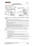
ORIGINAL
Assembly
Instructions
mbled and
er. Properly asse
bl
um
sT
po
m
Co
l
years.
thy compost for
hasing the Origina
al
rc
he
,
pu
r
ch
ri
fo
u
u
yo
yo
k
Than
on giving
oductive
w tumbler can go
ne
ur
yo
,
e beautiful and pr
ed
at
or
er
m
r,
op
ie
th
al
he
a
will give you
And that in turn
– naturally.
the
lawn and garden
assembled. All of
be
to
y
ad
re
d
pe
tools
s been ship
ly are the proper
mposTumbler ha
pp
Co
su
l
u
na
yo
gi
l
ri
al
O
–
ur
ed
Yo
includ
you will need are
parts and pieces
s
and the labor.
assembly proces
ep
st
y-b
ep
st
e
th
u through
signed to help yo
de
is
l
ua
an
m
is
ion.
Th
d painless operat
an
sy
eps
ea
an
it
e
and mak
ough there are st
th
al
,
on
rs
pe
e
by just on
n be completed
ca
y
bl
m
se
as
e
tir
nds!
The en
second pair of ha
a
ith
w
er
si
ea
on or
that would be
l ComposTumbler
na
gi
ri
O
ur
yo
y,
e
siest to assembl
sembly isn’t heav
ea
as
it
ed
d
et
fin
pl
m
ly
co
ab
e
ob
it. While th
You will pr
you intend to use
re
he
w
e
ac
pl
e
near th
to move.
lky and awkward
bu
t
ha
ew
m
so
drum.
is
it
the paint on the
ng
hi
tc
ra
sc
t
en
ev
th surface to pr
Work on a smoo
Dear Friend:
assembly.
actually start the
u
yo
re
fo
be
y
el
complet
job.
read this manual
lfway through the
Take the time to
ha
s
se
ri
rp
su
y
avoid an
all of them
That way you can
ake sure you have
m
d
an
w
lo
er.
be
t
h faster and easi
u Will Need” lis
uc
Yo
m
ls
y
bl
oo
m
“T
se
e
th
as
e
k
th
Chec
n make
e proper tools ca
list on
handy. Having th
against the parts
em
th
re
pa
m
co
e
rts included and
parts for both th
pa
e
e
th
th
of
l
er
al
ov
y
k
tif
ec
en
Then, ch
and can id
e sure you have
ak
M
4.
d
an
3
s
start.
Page
rum before you
D
er
bl
m
Tu
e
th
Frame and
:
Before you start
Tools You Will Need
Before you start, assemble the following tools:
g
g
g
g
g
g
g
3/8" wrench
7/16" wrench
3/4" wrench
Adjustable wrench
Regular screwdriver (flat head)
Phillips screwdriver (cross head)
Hammer
Everything else you will need is included with your ComposTumbler.
Parts For The Support Frame
4
1
7
10
6
11
PART
DESCRIPTION
QUANTITY
NEEDED
1
2
3
4
Lower Support
Support Spacer
Drive Handle
Upper Support
2
4
1
2
(with axle rod carriers)
5
6
7
8
9
10
11
3
8
ITEM NO.
9
5
2
Axle Rods
Drive Wheels
1/2"x 2" Bolt
Grip
Grip Cap
Spring Pin
#6 Screw
2
4
8
1
1
4
1
Parts For The Tumbler Drum
14
13
15
12
16
18
17 20
19
21
22
ED
RG
LA
N
E
23
24
25
W
VIE
26
28
27
29
30
Note: The Tie Rods (Item 16) have been shipped inside the Support Spacers
(item 2). Be sure to remove them before assembling the frame.
ITEM NO.
12
13
14
15
16
17
18
19
20
21
22
23
24
25
26
27
28
29
30
PART
DESCRIPTION
Drum Segment A
Drum Segment B
Endcap
Door Frame Segment
Tie Rod,1/4"x 363/4"
AeratorBase (outside)
AeratorCap (inside)
Latch Hook
Latch
Door
#10 Bolts
#10 Flat Washer
#10 Lock Washer
#10 Hex Nut
Acorn Nut, 1/4"
Bolt,1/4"x 31/4"
Wing Nut, 1/4"
Shoulder Bolt
#10 Lock Nut
QUANTITY
NEEDED
1
2
2
1
4
2
2
2
2
1
18
34
18
18
8
2
2
16
16
3
Support Frame Assembly
STEP 1:
Lower Support Assembly
Select:
g
g
g
2 Lower Supports (item 1)
2 Support Spacers (item 2)
4 1/2" x 2" Bolts (item 7)
A. Make sure you have removed the tie rods from inside
the support spacers.
B. Fasten one support spacer to lower support section
with 1/2" bolt as shown in the adjacent photograph.
After orienting the other lower support section in a
position where the straight and smaller ended uprights
are diagonally opposite each other, fasten this section
to the opposite end of the support spacer with 1/2" bolt.
C. With lower support sections held upright, as above, fasten the other support spacer in a similar
manner with 2 additional 1/2" bolts to form the assembly shown in the adjacent photograph.
STEP 2:
Upper Support
Assembly
Select:
g
g
g
2 Upper Supports (item 4)
2 Support Spacers (item 2)
4 1/2" x 2" Bolts (item 7)
A. With open end facing down, position one upper
support, parallel to a lower support spacer, over
the upright sections of the lower support assembly,
and oriented so that a small diameter end opposes
a straight section.
(Note: Upper support sections (item 4 in adjacent photo)
must be at right angles to lower support sections (item 1
in adjacent photo) to result in sufficient strength and stability
to support the drum.)
B. Slip the ends of the upper support fully into and over the uprights of the lower support section. Repeat with
the second support. Continued...
4
Support Frame Assembly
STEP 2 Continued:
C. Fasten the support spacers to the upper supports,
following the same procedure used in Step 1.
D. Now is the time to secure the 8 bolts that turn
into the support spacers. Using a 3/4" wrench,
snugly tighten each bolt to stabilize support frame.
STEP 3:
Axle & Drive Wheel
Assembly
Select:
2 Axle Rods (item 5)
4 Drive Wheels (item 6)
g
g
A. Slip the first axle through one of the axle rod
carriers on an upper support.
B. Place two drive wheels onto the axle inside the
framework, making sure that the smaller, slotted
ends of the wheels face away from each other and
toward the ends of the axle (see illustration).
C. Insert the end of the axle through the
corresponding carrier on the other upper support.
The two drive wheels are now suspended on the
axle between the upper supports.
D. Repeat the procedure with the second axle and
two remaining drive wheels.
E. Add a small amount of oil or grease to the end
of the shaft. Then spin the axle to work the lubricant
inside the axle support.
5
Support Frame Assembly
STEP 4:
Drive Handle Assembly
Select:
g
g
g
g
1
1
1
1
Drive Handle (item 3)
Grip (item 8)
Grip Cap (item 9)
#6 Screw (item 11)
A. Slide the Grip onto the end of the Drive Handle.
B. Push the stem of the Grip Cap into the end of the Drive Handle, aligning the holes.
C. Secure the Grip Cap to the end of the Drive Handle with the #6 Screw. Tighten
the Screw until just snug. Note: The head of the Screw will be in the hole of the
Drive Handle, locking the Grip Cap in position.
STEP 5:
Spring Pin Assembly
Select:
g
g
1 Drive Handle Assembly (step 4)
4 Spring Pins (item 10)
A. Decide which corner of the assembly the drive handle is to
be positioned on. (Any of the four corners will accept the handle assembly. The decision is entirely a factor of your convenience.) Insert the shaft of the handle into the end of the axle
rod at the corner.
B. Line up the holes in the handle shaft and the axle, then
using a hammer, gently drive a spring pin through all holes.
C. Drive a spring pin through the holes in each of the three
remaining ends of the axle rods. To hold the drive wheels properly, the spring pin should extend an equal amount
on each side of the rod at all four corners.
D. Move each drive wheel into position against its corresponding spring pin, lining up the slots in the drive wheel
with the pin. Slide the wheel over the pin at each corner.
The Support Frame for your ComposTumbler is now assembled
and ready to hold the drum. Move the frame into its final position
before placing the assembled drum on it. Double check to make
certain that all nuts and bolts are tightly secured.
The Frame should be carefully positioned on level ground to
insure best results. Uneven placement can make the Tumbler
harder to turn.
Before operating, lubricate the 4 axle rod carrier sections.
6
Tumbler Drum Assembly
STEP 1:
Initial Drum
Body Assembly
Select:
1 Drum Segment A (item 12)
2 Drum Segments B (item 13)
g
10 #10 Bolts (silver) (item 22)
g
10 #10 Flat Washers (item 23)
g
10 #10 Lock Washers (item 24)
g
10 #10-32 Hex Nuts (item 25)
g
g
A. Place Drum Segment A on a
flat, smooth work surface with the flanged mixing fins facing upright. Align one Drum Segment B
along one side of Segment A, matching up the holes in the fins.
B. Fasten Segment A to first Segment B using:
1 #10 Bolt (silver)
1 #10 Flat Washer
1 #10 Lock Washer
1 #10 Hex Nut
at each of the five holes. Hand tighten all bolts.
C. Attach the other Segment B to the other side of
Segment A the same way.
D. Using the slotted screwdriver and 3/8" wrench,
tighten all the fasteners.
STEP 2:
Drum Assembly
Select:
1 Endcap (item 14)
1 Drum Body Assembly (from Step 1)
g
g
A. Place the endcap, name plate down, on work
surface. Note position of the screen on the endcap.
Carefully pick up the 3 sectioned partially assembled
drum from Step 1 and by bending it with the mixing
fins on the inside, fit it into the rim of the endcap,
forming three-quarters of the cylinder. Be careful to
locate the center panel (Segment A) adjacent to the
screen and fit the mixing fins on both sides of this
segment into the alignment slots of the endcap.
7
Tumbler Drum Assembly
STEP 3:
Latch Attachment
Select:
g
g
g
g
g
g
g
g
1 Door Frame Segment (item 15)
2 Latches (item 20)
2 Latch hooks (item 19)
8 #10 Bolts (silver) (item 22)
8 #10 Flat Washers (item 23)
8 #10 Lock Washers (item 24)
8 #10-32 Hex Nuts (item 25)
1 Door (item 21)
A. With the Door Frame Segment resting on the work
surface, attach the Latches to the panel on top of the raised mounting
holes with the hooks toward the opening using:
1 #10 Bolt (silver)
1 #10 Flat Washer
1 #10 Lock Washer 1 #10-32 Hex Nut
on each side of both Latches. Be sure the Bolt is on the underside
of the panel in the recess, with the Flat Washer, Lock Washer and
Hex Nut on top of the Latch. Use the slotted screwdriver and
3/8" wrench to tighten all Latch mounting fasteners.
B. Position the Latch Hooks on the other side of the panel opening with the hook ends toward the opening.
Secure them the same way as the latches, but make the fasteners only hand tight.
C. Position the Door in place on the panel. Fit the notches on one end of the Door into the Hooks on the panel,
and the hooks of the Latches into the notches on the other side of the Door. Close the latches to check their
tension, they should "snap" closed, but should not be too difficult to open. Loosen and adjust the Latch Hook
fasteners to get the proper tension, then tighten them with the slotted
screwdriver and 3/8" wrench.
D. Remove the Door for the next step.
STEP 4:
Door Frame Assembly
Select:
g
g
g
8
16 Shoulder Bolts (gold) (item 29)
16 #10 Flatwashers (item 23)
16 #10-24 Locknuts (item 30)
A. Carefully fit the Door Frame Segment (with latches installed) into
the last open space of the Endcap to complete the Drum cylinder,
overlapping the adjoining segments and lining up the hole patterns
along both sides and into the rim of the Endcap. Continued...
Tumbler Drum Assembly
STEP 4 Continued:
B. Starting from the bottom and working from the
outside, fasten the Door Frame Segment to the other
Drum segments using:
1 Shoulder Bolt (gold)
1 #10 Flat Washer
1 #10-24 Lock Nut
at each of the eight slots on both sides of the Door
Frame Segment. The Washers and Lock Nuts should
be fastened inside the Drum body. The slotted holes
in these Drum Segments will allow for adjustment to
make placement of the second Endcap easier. Use
the Phillips screwdriver and 3/8" wrench to turn the
Lock nuts onto the Bolts until the nut bottoms out
against the shoulder of the bolt.
The shoulder bolt should spin freely in the slotted hole
and not be so tight that the bolt and nut clamp the metal
panels together. If they do, loosen the nut 1/4 turn. This is
to accommodate subsequent movement of these panels
during operation resulting from changes in temperature.
STEP 5:
Second Endcap Assembly
Select:
1 Endcap (item 14)
4 Tie Rods, 36 3/4" (item 16)
8 Acorn Nuts 1/4" (item 26)
g
g
g
A. Position the second endcap over the open end of
the drum assembly, lining up the endcaps so that the
screens are directly opposite each other and the
flanges in the drum match the slots in the cap.
B. Lining up the two flanges furthest from the door
frame with their corresponding alignment slots, work
that part of the endcap carefully down onto the
drum. Then, working through the opening in the door
frame, fit the two remaining flanges into their slots, adjusting the fit of the drum as necessary by sliding the
door frame slightly. Be sure that the edges of the drum fit snugly into the rim of the endcap all the way around
and that the flanges inside the drum are all fitted into the alignment slots on the cap.
C. Thread an acorn nut onto the end of one tie rod just until the nut holds (about two turns). Insert the other
end of the tie rod through one of the four holes in the top endcap and run the rod down through the opposite
hole in the bottom endcap. (Lead-ins have been provided to make this step easier.)
Continued...
9
Tumbler Drum Assembly
STEP 5 Continued:
D. Thread a second acorn nut onto the exposed end of the rod. If there is not enough exposed
thread to start the nut or if the rod will not go all the way through the drum, double check to
make sure the drum edges are fitted all the way into the rim of the cap and the flanges are in
the alignment slots. If there is still a problem, loosen the acorn nut on the first end of the tie rod
or press firmly on both endcaps to seat them fully.
E. Repeat steps “c” and “d” with remaining three tie rods and six acorn nuts, connecting
the three remaining pairs of holes in endcaps. When all four rods have been positioned and
secured, tighten all eight acorn nuts using an adjustable wrench at one end and a 7/16”
wrench at the other. Note: Do not overtighten.
STEP 6:
Aerator Assembly
Select:
g
g
g
g
g
2
2
2
2
1
Aerator Outside Sections (item 17)
Aerator Inside Sections (item 18)
Bolts, 1/4" x 31/4" (item 27)
Wing Nuts (item 28)
Door (item 21)
A. Position one Aerator Outside Section on the outside
of the Door.
B. Insert one Bolt through the Aerator Outside Section
and hole in the Door.
C. Slip one Aerator Inside Section over the Bolt on
the inside of the Door, threading a Wing Nut onto
the end of the Bolt until hand hand tight.
Be careful not to overtighten the assembly.
D. Repeat “a”, “b” and “c” with second aerator over
the second hole in the Door.
E. Check both aerators to make sure that the curve
of the Door when it’s in place on the drum and the
contour of the outer portion of the aerator match,
and then apply slight pressure on Wing Nuts to hold
assembly firmly in place. Do not overtighten.
F. Attach Door to Drum.
10
Completion
Completion
STEP 7:
Placement of Drum
on Support Frame
A. Check the Support Frame to make sure
that all four drive wheels are pulled out
against the flanges on the axle rod carriers
and that the spring pins are all snugly
fitted into the slots in the wheel hubs.
B. Place the drum on the Support Frame so
that when the door opening is positioned
on the same side of the Frame as the drive
wheel handle, the latches are on the
bottom of the opening and the latch
brackets are on top.
C. Adjust the position of the drum so that it
is centered and resting evenly on all four
drive wheels. The ridged edges of the
endcaps should be sitting firmly on the
gear sections of the wheel drives.
Your ComposTumbler is now completely assembled and ready to use. Read your
operating instructions manual, "How to Make Superior Compost," carefully
before starting your first batch of compost.
11
30 Wright Avenue • Lititz (Lancaster County), PA 17543
1-888-820-5114
If you have any questions or problems with your Original ComposTumbler assembly that aren’t covered by this booklet,
please call us at 1-888-820-5114 & We’ll be happy to help!
© PBM Group, Inc. 2003
P/N 2072-00 Rev 0(8/02)