1
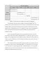
problem due to the fact that the relay I was using required a minimum of 3 Volts to work. The 3
volts is used to power a inductor that when powered repels a length of wire to form a switch.
Pin 1 and 2 of Figure #1 would be connected to the Microcontrollers output pin and the other
to the ground. Pin 3 would be connected to the power source while Pin 5 is connected to the
motor Vin. Once the inductor is powered the switch would move allowing the power from Pin 3
to move to Pin 5, completing the circuit. However this doesn't work with a Mechanical Relay,
because Mechanical relays do not work below a 3Volt input to the inductor. Where the
Microcontroller supplies 1-2 Volts. This can be solved using a Solid State Relay where the
voltage can be from mV to a high voltage.
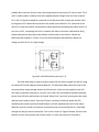
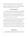
Figure #2: A Solid State Relay with pins 1-4.
The Solid State Relay is used to control a switch for the motor to power on and off, using
an Infrared LED and an adjacent Infrared detector. The Solid State Relay solves the issue of the
microcontrollers output voltage because it will work with 1 Volt or more supplied to the LED.
This Relay in particular activates at 1.1 Volts. Pins 1 and 2 are connected to the Microcontroller
to one of the PIO pins and the other to Ground. Where Pins 3 and 4 are connected to the motor
and the motor's power source. Once the PIO port is activated 1 Volt with power the LED
connecting the switch from the infrared Detector, this will complete the circuit to the motor.
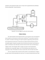
With this circuit the motor is not directly connected to the microcontroller but it is controlled
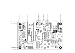
through the relay by the microcontroller. This circuit is shown in Figure #3 below, there are two
identical circuits in this project one for each motor. To note, the motors are reversed in