1
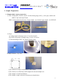
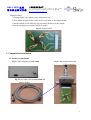
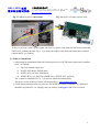
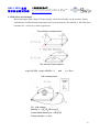
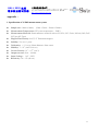
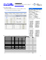
HALL 8000 系 列
霍尔效应测试仪器
上海沃埃得有限公司
上 海 市 共 和 新 路 2449 号 泛 欧 现 代 大 厦 819 室 邮 编 :200072
电 话 :(021)51806194*807 Mobile:13918893919 奚 雪 峰
Http://www.worldwide-china.com
HALL8800
HALL EFFECT MEASUREMENT SYSTEM
User Manual
0
HALL 8000 系 列
霍尔效应测试仪器
上海沃埃得有限公司
上 海 市 共 和 新 路 2449 号 泛 欧 现 代 大 厦 819 室 邮 编 :200072
电 话 :(021)51806194*807 Mobile:13918893919 奚 雪 峰
Http://www.worldwide-china.com
Contents
1. Sample Preparation …………………………Page 2
1.1 Sample ohmic contact preparation ……………. Page 2
2. Composition Installation ……………………Page 3
2.1 Hardware installation ……………………………Page 3
2.2 Software installation ……………………………. Page 5
3. Measurement …………………………………Page 6
3.1 Measurement preparation ……………………….Page 6
3.2 Resistivity measurement …………………………Page 7
3.3 Hall effect measurement …………………………Page 8
4. Hall Effect Measurement Theory ……………Page 9
4.1 Hall effect …………………………………………. Page 9
4.2 Hall effect measurement …………………………..Page 10
Appendix …………………………………………Page 11
1. Specification of Hall measurement system …………Page11
2. Test data example ………………………………… Page12
1
HALL 8000 系 列
霍尔效应测试仪器
上海沃埃得有限公司
上 海 市 共 和 新 路 2449 号 泛 欧 现 代 大 厦 819 室 邮 编 :200072
电 话 :(021)51806194*807 Mobile:13918893919 奚 雪 峰
Http://www.worldwide-china.com
1. Sample Preparation
1.1 Sample ohmic contact preparation
1. Tool: Cutting knife, scissors, tweezer, In ball, heating stage (200℃), silver glue, double side
adhesive tape and sample board.
Ohmic contact material (reference): N type sample : use In ball, P type sample : use InZn ball.
U side
2. Steps:
1) Cutting sample with proper size (5×5 to 20×20 mm2).
2) In ball in four points of sample using “U side” of tweezer.
3) Then annealing at 200℃ for 2min by heating stage.
In Ball
In Ball
3 Sample structure: Top view.
1) The contacts are on the circumference of the sample.
2) The contacts are sufficiently small compared to the total sample area.
3) The sample is of uniform thickness.
4) The sample is singly connected (contains no isolated holes).
2
HALL 8000 系 列
霍尔效应测试仪器
上海沃埃得有限公司
上 海 市 共 和 新 路 2449 号 泛 欧 现 代 大 厦 819 室 邮 编 :200072
电 话 :(021)51806194*807 Mobile:13918893919 奚 雪 峰
Http://www.worldwide-china.com
4 Sample board
1) Cutting double side adhesive tape with proper size.
2) Then attach the tape on the center of the cross mark of the sample board.
3) Put the sample on the adhesive tape on sample board to fix the sample.
4) Put the spring tips on contact In ball of sample.
Fig.1.1 Sample board
2. Composition Installation
2.1 Hardware installation
Fig.2.1 (a) Front panel of HALL8800
Fig.2.1 (b) Sample holder and
Cable connector
Fig.2.1 (c) Cable connects HALL8800 and
Sample holder
3
HALL 8000 系 列
霍尔效应测试仪器
上海沃埃得有限公司
上 海 市 共 和 新 路 2449 号 泛 欧 现 代 大 厦 819 室 邮 编 :200072
电 话 :(021)51806194*807 Mobile:13918893919 奚 雪 峰
Http://www.worldwide-china.com
Fig. 2.1 (d) Rear panel of HALL8800
Fig. 2.1 (e) PC or Laptop express card
In Fig. 2.1(d), blue circle is power input; red circle is express card connector and connection cable,
black circle is chassis ground. Fig. 2.1 (e) shows the express card and connection cable connects
chassis and PC (or Laptop).
2.2 Software installation
1. After hardware installation finish, the following drivers of NI PXI card used must be installed
in PC (or Laptop).
1) Labview runtime engine 8.6.1
2) NI PXI 2503 Matrix Switch driver
3) NI PXI 4132 precision SUM driver
4) NI PXI 4070 6 1/2 Digit Flex DMM driver (NI PXI 4071 optional)
The 1) must be installed first, 2), 3), 4) drivers should be installed later.
The latest version of drivers can be downloaded from www.worldwide-china.com
2. A Hall Sensor Measurement.exe software (for NI PXI 4070 and NI PXI 4071 are different)
should be copied on PC (or Laptop), and you need to put Keypro USB on PC to start it.
4
HALL 8000 系 列
霍尔效应测试仪器
上海沃埃得有限公司
上 海 市 共 和 新 路 2449 号 泛 欧 现 代 大 厦 819 室 邮 编 :200072
电 话 :(021)51806194*807 Mobile:13918893919 奚 雪 峰
Http://www.worldwide-china.com
Fig.2.2
5
HALL 8000 系 列
霍尔效应测试仪器
上海沃埃得有限公司
上 海 市 共 和 新 路 2449 号 泛 欧 现 代 大 厦 819 室 邮 编 :200072
电 话 :(021)51806194*807 Mobile:13918893919 奚 雪 峰
Http://www.worldwide-china.com
3. Measurement
3.1 Measurement preparation
1. Hardware preparation
1) The HALL8800 was connected to PC (or Laptop) by express card and connection cable.
2) The HALL8800 was connected to Hall sample holder by connection cable.
2) Turn on the power of HALL8800 first, then turn on and open PC (or Laptop), the
PWR and LINK on HALL8800 shows light on (Fig. 3.1 (a)).
2. Software preparation
1) Put Keypro USB on PC (or Laptop) first.
2) Execute the Hall Sensor Measurement.exe in EXE_4070 (or EXE_4071).
3) Fill sample ID, Thickness, Dimensions, and input magnetic induction filed B (default : 6800G)
filed and click OK. (Fig.3.1 (b))
Fig. 3.1.(a) PWR and LINK light on
Fig.3.1 (b)
3. Put the sample board with sample into the
sample holder (with connector).
Hall
Fig. 3.1 (c)
The sample should be faced to the yellow
mark on Hall sample holder.
6
HALL 8000 系 列
霍尔效应测试仪器
上海沃埃得有限公司
上 海 市 共 和 新 路 2449 号 泛 欧 现 代 大 厦 819 室 邮 编 :200072
电 话 :(021)51806194*807 Mobile:13918893919 奚 雪 峰
Http://www.worldwide-china.com
3.2 Resistivity measurement
1. Execute the Hall Sensor Measurement.exe and click Ohmic button under W/O B filed to check
the ohmic contact of sample. (Fig.3.2 (a), Fig.3.2 (b))
2. The resistance R12, R23,..will be shown at left side of software display board (yellow circle in
Fig.3.2 (b)). You may check if the connection between sample and sample board is good or not
by compare R12, R23, to the resistance value which measured by Volt-Ohm-Milliammeter.
3. If the “Out of Range” light shows red (green circle in Fig.3.2 (b)), adjust I (A) and limit V (V)
(red circle in Fig.3.2 (b)). And measure Ohmic again till the light shows green.
4. I (A) can be adjusted from 10-7 A to 0.1 A, limit (V) have the max value 100 V, and the total
power can not be large than 2 W.
5. Check the contact, linear I-V curve shows good ohmic contact (blue circle in Fig.3.2 (b)).
Fig.3.2 (a)
Fig.3.2 (b)
Ohmic measurement without B
(Permanent magnet)
Good ohmic contact shows linear I-V curve (blue circle)
6. After Ohmic measurement finish, click Measure button under W/O B filed to measure the
resistance of sample. (Fig. 3.3 (a)).
7. If the any of V43, V34,….( blue circle in Fig. 3.3 (a)) shows “NaN”, adjust DMM Range (V)
(red circle in Fig. 3.3 (a)), and measure again till the “NaN” disappear.
8. The DMM Range (V) can be adjusted from 100mV to 300V, it is recommended to adjust the
DMM Range (V) near and a little large than the value which shows in V43,V34,..(blue circle in
Fig. 3.3 (a)).
7
HALL 8000 系 列
霍尔效应测试仪器
上海沃埃得有限公司
上 海 市 共 和 新 路 2449 号 泛 欧 现 代 大 厦 819 室 邮 编 :200072
电 话 :(021)51806194*807 Mobile:13918893919 奚 雪 峰
Http://www.worldwide-china.com
3.3 Hall effect measurement
1. After V43, V34,.. measurement finish, the Apply +B measurement button appears
(Fig. 3.3 (a)). Put the sample board and the sample surface forward to N (N to S) (Fig. 3.3 (b)),
and click OK button.
Fig. 3.3 (a)
Fig.3.3 (b) Apply the + B (N -> S ) to the sample.
2. After Apply +B measurement finish, Apply –B button appears (Fig.3.3 (c)). Let the sample
surface forward to S (S to N), and click OK button to execute measurement.
3. After apply B measurement finish, the value V24P,…V24N,.. will be shown (blue circle in
Fig.3.3 (c)) and Measurement Complete button will appears.
4. The measurement data Rs (sheet resistance), Rho (resistivity), VH (Hall voltage), RH (Hall
coefficient), Ns/Ps , N/P (Carrier concentration ) , Mob (Mobility) will be shown (blue circle in
Fig.3.3 (d))
5. If VH shows positive (negative) value, the majority carrier of the sample is p (n) type.
6. Click Save button, save the test data.
8
HALL 8000 系 列
霍尔效应测试仪器
上海沃埃得有限公司
上 海 市 共 和 新 路 2449 号 泛 欧 现 代 大 厦 819 室 邮 编 :200072
电 话 :(021)51806194*807 Mobile:13918893919 奚 雪 峰
Http://www.worldwide-china.com
Fig.3.3 (c)
Fig.3.3 (d)
7. Finish the measurement: Click the Exit button, turn off PC (or Laptop) first, and then
turn off the HALLOOK T300 system.
4. Hall Effect Measurement Theory
4.1 Hall effect
The history of the Hall effect begins in 1879 when Edwin H. Hall discovered that a small
transverse voltage appeared across a current-carrying thin metal strip in an applied magnetic field.
9
HALL 8000 系 列
霍尔效应测试仪器
上海沃埃得有限公司
上 海 市 共 和 新 路 2449 号 泛 欧 现 代 大 厦 819 室 邮 编 :200072
电 话 :(021)51806194*807 Mobile:13918893919 奚 雪 峰
Http://www.worldwide-china.com
4.2 Hall effect measurement
By measuring the Hall voltage VH, the majority carrier sheet density can be decided. And by
combination of a Hall measurement and resistivity measurement , the mobility µ, thin film sheet
resistance Rs , resistivity ρ can be figured out.
The resistivity measurement
The van der Pauw method
exp(-πRA/Rs) + exp(-πRB/Rs) = 1
and
ρ = Rs d
Hall measurement
VH : Hall voltage
Mobility µ =|VH|/RS IB =1/qnsRS
Carrier sheet density ns = IB/q|VH|
Carrier density n = ns/d
10
HALL 8000 系 列
霍尔效应测试仪器
上海沃埃得有限公司
上 海 市 共 和 新 路 2449 号 泛 欧 现 代 大 厦 819 室 邮 编 :200072
电 话 :(021)51806194*807 Mobile:13918893919 奚 雪 峰
Http://www.worldwide-china.com
Appendix :
1. Specification of 3S Hall measurement system
♦
♦
♦
Sample size: 10mm x10mm, (5mm x 5mm ~ 20mm x 20mm)
Measurement Temperature: RT (room temperature ~ 300K)
Measurement Material: Semiconductors material such as Si, SiGe, SiC, GaAs, InGaAs, InP, GaN
(N Type & P Type)
♦
♦
♦
♦
Magnet Flux Density: 0.68T, 1T Permanent magnet
Stability: 2% over 1 years
Uniformity: +/- 1% over 20mm diameter from center
Mobility: 1 ~ 107 (cm2/Volt-sec)
♦
♦
♦
♦
Carrier Density: 107 ~ 1021 (cm-3)
Output current: 2nA ~ 100mA
Input Voltage: 1µV ~300V
Resistivity: 10-5 ~107 (Ω-cm)
11
HALL 8000 系 列
霍尔效应测试仪器
上海沃埃得有限公司
上 海 市 共 和 新 路 2449 号 泛 欧 现 代 大 厦 819 室 邮 编 :200072
电 话 :(021)51806194*807 Mobile:13918893919 奚 雪 峰
Http://www.worldwide-china.com
2. Test data example
(1) Save the measurement data to a txt file (right) by using
Save button after measurement complete.
(2) You can organize your measurement data in excel (example)
Dimension 1x1 cm^2
Sample
(nm)
Applied current (A)
Limit Voltage (V)
R (ohm)
Results :
Rs (ohm/sq)
Rho (ohm-cm)
VH (V)
RH (m^3/C)
Ns/Ps (1/cm^2)
N/P (1/cm^3)
Mob. (cm^2/V-s)
1
62
Applied Magnetic Field : B = 6800 (G)
2
3
4
65
70
75
1.00E-04
1.00E+01
~ 35 KΩ
1.00E-03
1.00E+01
~ 65 Ω
1.00E-02
1.00E+01
~ 7Ω
1.00E-02
1.00E+01
~ 6Ω
3.02E+04
1.87E-01
-1.65E-04
-1.51E-07
-2.57E+14
-4.14E+19
8.06E-01
4.74E+01
3.08E-04
-4.31E-06
-4.12E-10
-9.84E+16
-1.51E+22
1.34E+00
6.00E+00 4.68E+00
4.20E-05
3.51E-05
-2.46E-05 -1.93E-05
-2.54E-10 -2.13E-10
-1.72E+17 -2.20E+17
-2.46E+22 -2.93E+22
6.03E+00 6.07E+00
Note 1. R (ohm) is the averge of R12, R23,R34,... data under Ohmic measurement.
Note 2. Rs (sheet resistance), Rho (resistivity), VH (Hall voltage), RH (Hall coefficient),
Ns/Ps (sheet carrier concentration), N/P (carrier concentration) , Mob (mobility).
Note 3. When VH shows positive (negative) value, the majority carrier of the sample is p (n) type.
12