1
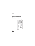
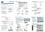
Long Pipe Color Changer
User Manual
Lamp: 252pcs (R84/G84/B84) x10mm LEDs in 4 groups, each group 63 (Red21/Green21/Blue21) LEDs
CAUTION!
Keep this device away from rain and moisture!
Unplug mains lead before opening the housing!
For your own safety, please read this user manual carefully before your initially start-up!
Every person involved with the installation, operation and maintenance of this device has to
- be qualified
- follow the instructions of this manual
- consider this manual to be part of the total product
- keep this manual for the entire service life of the product
- pass this manual on to every further owner or user of the product
- include every supplementary update with the original manual
Before your initial start-up, please make sure that there is no damage caused during shipment.
Should there be any, do not use the device and consult your supplier.
SAFETY INSTRUCTIONS
This device has left our premises in absolutely perfect condition. In order to maintain this
condition and to ensure a safe operation, it is absolutely necessary for the user to follow the safety
instructions and warning notes written in this user manual.
Important: Damages caused by the disregard of this user manual are not subject to
warranty. The dealer will not accept liability for any resulting defects or problems.
If the device has been exposed to drastic temperature fluctuation (e. g. After delivery), do not
switch it on immediately. The arising condensation water might damage your device. Leave the
device switched off until it has reached room temperature.
This device falls under protection-class I. The power plug must only be plugged into a
protection-class I outlet. The Yellow/Green conduct should be earthed.
Do not connect this device to a dimmer pack.
For replacement, use same type and rating lamps or fuses only.
Always plug in the power plug least. Make sure the power cord is never crimped or damaged by
sharp edges. Check the device and the power cord from time to time.
Never let the power cord come into contact with other cables! Handle the power cord and all
connections with the mains with particular caution! Only handle the power cord by the plug.
Never pull out the plug by tugging the power cord. Make sure the available voltage is not higher
than that stated on the rear panel.
Always disconnect from the mains, when the device is not in use or before cleaning it.
Keep the device upright! For overhead use (mounting height > 100cm), always fix it with a safety
rope.
Keep away children and amateurs from the device! Never leave the device running unattended!
There are no serviceable parts inside the device except for the lamp and fuses. Maintenance and
service operations cab be only carried by authorized dealers.
Please note that damages caused by manual modifications on the device or unauthorized operation
by unqualified persons are not subject to warranty.
OPERATING DETERMINATIONS
This device is a lighting effect for creating decorative effects for discotheques, stages etc. It is
allowed to be operated only with an alternating current of AC 90 - 250V 50Hz, and is designed for
indoor use only.
This device is not designed for permanent operation. Consistent operational breaks will ensure that
the device will serve you for a long time without defects.
Operate the device only after having familiarized with its functions. Check the device carefully to
see if the housing is firmly closed and with all screws tightly fastened.
Do not shake the device. Avoid brute force when installing or operating.
When choosing the installation-spot, please make sure that the device is not exposed to extreme
heat, moisture or dust. There should not be any cables lying around. You endanger your own and
the safety of others!
The minimum distance between the device and illuminated surface is 1 meter.
Make sure that the area below the installation place is blocked when rigging, derigging or
servicing the device.
Always fix the device with at least one safety rope. Fix the safety ropes at the correct hole only.
The maximum ambient temperature ta=45oC must never be exceeded.
Do not permit operation by persons not qualified for operating the device. Most damages are the
result of unprofessional operation!
Please use the original packaging if the device is to be transported.
Please consider that unauthorized modifications on the device are forbidden due to safety reasons!
If this device will be operated in any way different to the one described in this manual, it may
suffer damages and the guarantee becomes void. Furthermore, any other operation may lead to
dangers like short-circuit, burns, electric shock, etc.
DESCRIPTION
L ED LA MPS
AC 90 -250V
DMX INPUT DMX OUTPUT
1
2
5
ME NU
UP
3
CONTROL PANEL
1. DISPLAY WINDOW
2. MENU BUTTON
3. UP BUTTON
D O WN
E N TE R
4
4. DOWN BUTTON
5. ENTER BUTTON
SETUP
1.
Rigging the device
DANGER OF FIRE!
Make sure there is no inflammable material nearby during installing. Follow the instructions
stated on the housing and manual of this device.
DANGER TO LIFE!
Please consider the respective national norms during the installation! The installation must
only be carried out by an anthorized dealer!
This device can be installed directly onto a truss, wall or ceiling in any orientation without altering
its operation characteristics.
Use proper bolts or to mount the device via its mounting bracket. The mounting bracket should be
attached to the device by tighten the fixation screws.
Always use at least one safety rope as secondary safety attachment. Always use safety ropes that
can hold at least 10 times the weight of the device.
Using safety ropes through the hole on the housing. Never use the mounting bracket for safety
ropes.
The installation should also be secured with an appropriate catch net, so that no part of the device
can fall down if the main attachment fails.
When rigging, derigging or servicing the device, staying in the area below the installation place,
on bridges, under high working places and other endangered places is forbidden.
The operator has to make sure that safety-relating and machine-technical installations are
approved by an expert before taking into operation for the first time and after changes before
taking into operation another time.
The operator has to make sure that safety-relating and machine-technical installations are
approved by an expert after every four year in the course of an acceptance test.
The operator has to make sure that safety-relating and machine-technical installations are
approved by a skilled person once a year.
Machine-technical installations in the sense of these instructions are all technical installations and
working material used for operating places of events and productions for scenery presentations.
Procedure:
The installation should be attached outside areas where persons may walk by or be seated.
IMPORTANT! OVERHEAD RIGGING REQUIRES EXTENSIVE EXPERIENCE, including
(but not limited to) calculating working Ioad limits, installation material being used, and periodic
safety inspection of all installation material and the device. If you lack these qualifications, do not
attempt the installation yourself, but instead use a professional structural rigger. Improper
installation can result in bodily injury and or damage to property.
The installation has to be attached out of the reach of people.
If the device is to be lowered from the ceiling or high joists, professional trussing systems have to
be used. The device must never be fixed swinging freely in the room.
Caution:
Device in hanging installations may cause servere injuries when crashing down! If you have
doubts concerning the safety of an installation, do not install the device!
If the device is to be installed to a trussing system, use an appropriate clamp.
The maximum drop distance must never exceed 200 mm.
2.
Connection to mains
Connect the device to mains with the enclosed power plug. The occupation of the connection
cables is as below:
Cable color
Pin
International
brown
live
L
blue
neutral
N
yellow / green
earth
The earth has to be connected.
3. DMX 512 connection
The wires must not come into contact with each other, otherwise the fixtures will not work at all,
or will not work properly.
Only use a stereo shielded cable and 3-pin XLR-plugs and connectors in order to connect the
controller with the fixture or one fixture with another.
Occupation of the XLR-connection:
If you are using controllers with this occupation, you can connect the DMX-out-put of the
controller directly with the DMX-input of the first device in the DMX-chain. If you wish to
connect DMX-controllers with other XLR-outputs, you need to use adapter-cables.
Building a serial DMX-chain:
Connect the DMX-output of the first device in the DMX-chain with the DMX-input of the next
device. Always connect one output with the input of the next device until all devices are
connected.
Caution: At the last device, the DMX-cable has to be terminated with a terminator. Solder a 120
Ωresistor between Data (-) and Data (+) into a 3-pin XLR-plug and plug it in the DMX-output of
the last device.
4. DMX start address setting
The control panel on the housing of the device allows you to assign the DMX start address, which
is defined as the first channel from which the device will respond to the controller.
This device has 17 DMX channels. If you set, for example, the start address to channel 1, the
device will use the channels # 1st to 17th for control. The first available channel for the next
fixture will be the 18th. Please be sure that you do not have any overlapping channels in order to
control each device correctly and independently from any other fixture on the DMX chain.
If two, three or more devices are addressed similarly, they will work similarly.
For address setting follow this procedure:
1) Press the Menu button until it shows -AXXX-. The XXX is the DMX address you selected last
time.
2) Press Enter button.
3) Press the UP or Down button to select from A001 - A512.
4) Press Enter button to save or Menu button to exit.
OPERATION
1. Working modes
This device has 4 working modes, DMX, Sound-active, Auto and Master-slave mode.
2. Auto mode
Press the Menu button until it shows -dnCo-, -Auto-, -Soud-, or SLAU- in the display. What will
be shown in the display is your last saved setting.
If it is not -Auto- in the display, press Enter button and then press Up or Down buttons to select
the -Auto-.
Press the Enter button, the Auto operation is selected.
Press the Menu button until it shows CL01 - CL16. These are the different Auto programs.
Press the Enter button.
Press the UP/Down button to select from CL01 - Cl16.
Press Enter button.
Press the Menu button until it shows SP01 - SP16. These are the speed of auto operation.
Press the Enter button.
Press the UP/Down button to select from SP01 - SP16. 16 is the fastest. 01 is the slowest.
Press the Enter button.
Press the Menu button until it shows St01 - St32. These are the strobe speeds.
Press the Enter button.
Press the UP/Down button to select from St01 - St32. 32 is the fastest. 01 is the slowest.
Press the Enter button.
Now the device will be operated automatically according to the program and in the speed you
selected.
3. Sound-active mode
This device is not designed with the sound operation. The -Soud- option in the menu has no
function.
4. Master-slave mode
Master device setup
Select a device as the Master device. All other devices will be slave device. Disconnect the
devices from the DMX controller.
For the Master device, select Auto operation for it according to the above steps.
Slave device setup
Press the Menu button until it shows -dnCo-, -Auto-, -Soud-, or SLAU- in the display. What will
be shown in the display is your last saved setting.
If it is not -SLAU- in the display, press Enter button and then press Up or Down buttons to select
the -SLAU-.
Press the Enter button, the device is selected as a slave device.
For all slave devices in a Master-slave chain, you must select -SLAU- by the control panel.
5. DMX mode
Press the Menu button until it shows -dnCo-, -Auto-, -Soud-, or SLAU- in the display. What will
be shown in the display is your last saved setting.
If it is not -dnCo- in the display, press Enter button and then press Up or Down buttons to select
the -dnCo-.
Press the Enter button, the DMX operation is selected.
Press the Menu button until it shows -AXXX-. The XXX is the DMX address you selected last
time.
Press Enter button.
Press the UP or Down button to select from A001 - A512.
Press Enter button.
In the DMX mode you can control the device via a DMX controller.
DMX channels
C H A N N EL
1
2
3
4
5
6
7
8
9
10
11
12
13
14
15
16
17
D M X VA L U E
DE SC RI PT I ON
000- 020
02 1-040
DI M ME R(CHA NN EL 2-17 DIMME R VA LID)
STROBE( CHA NN EL 2 SPEED . CHA NN EL 3 -17
DI MME R VALI D)
AU T O(EN TIRE CO LO R-CHA NG I NG)
AU T O(FULL COL O R-CHA NG ING )
AU T O( FULL COL O R-CHA SING)
AU T O(FULL COL O R-PL USIN G)
AU T O( TWO -GRO UP MO VIN G)
AU T O(TH REE-G R OU P M OV ING)
041- 060
061- 080
081- 100
101- 120
121- 140
141- 160
161- 180
181- 200
201- 220
221- 230
23 1-240
24 1-255
00 0-255
00 0-255
00 0-255
00 0-255
00 0-255
00 0-255
00 0-255
00 0-255
00 0-255
00 0-255
00 0-255
00 0-255
00 0-255
00 0-255
00 0-255
00 0-255
AU T O( FOU R-GRO UP MOV IN G)
AU T O(FULL COL O R-FAD ING)
TH U N DE R ST ROBE
MI X ED EFFECT + S TROBE
RAN DO M STROBE
DI M ME R(CHA NN EL 2-17 DIMME R VA LID)
AL L LED S GEN ERA L DIM ME R/SPEE D
AL L REDS L ED DIM MER (0% - 100% )
AL L GREE N L EDS D IMM ER ( 0% - 100% )
AL L BLUE LED S DI MMER (0 % - 100%)
1ST GRO UP RE D LED DI MME R (0% - 100%)
1ST GRO UP GR EE N L ED DIM MER (0% - 100%)
1ST GRO UP BL UE LED DI MM E R (0% - 100% )
2ND G ROU P R ED LED D IMM ER (0% - 100% )
2ND G ROU P G REEN LED DI M ME R( 0% - 100 %)
2ND G ROU P B LUE LE D D IMM ER(0% - 100% )
3RD GRO UP R E D L ED DIM M ER (0% - 100% )
3RD GRO UP G REEN LE D D IM MER ( 0% - 100 %)
3RD GRO UP B L UEL ED DIM M ER (0% - 100% )
4TH G RO UP R ED LED DI MME R (0% - 100% )
4TH G RO UP G REE N L ED DIM MER(0% - 100 %)
4TH G RO UP B LUE LE D D IMM ER(0% - 100% )
CLEANING AND MAINTENANCE
The Operator has to make sure that safety-relating and machine-technical installation are inspected
by an expert after every four years in the course of an acceptance test.
The operator has to make sure that safety-relating and machine-technical installations are
inspected by a skilled person once a year.
The following points have to be considered during the inspection:
1. All screws used for installing the devices or parts have to be tightly connected and must not be
corroded.
2. There must not be any deformations on the housing, fixations and installation spots (ceiling,
suspension, trussing, etc.).
3. The electric power supply cables must not show any damages, material fatigue (e.g. porous
cables) or sediments. Furthur instructions depending on the installation spot and usage have to be
adhereed by a skilled installer and any safety problems have to be removed.
DANGER TO LIFE!
Disconnect from mains before starting maintenance operation!
There are no servicable parts inside the device except for the lamp and the fuse. Maintenance and
service operation can be only carried by a authorized dealer.
Should you need any spare parts, please use genuine parts. Should you have further questions,
please contact your dealer.
TECHNICAL SPECIFICATIONS
Power supply:
Power consumption:
Lamp type:
Contr ol mode:
Dimmension / Carton:
Net / Gross weight:
90 - 25 0 V AC
20 W m ax
252 pieces LE D lamps, diameter 10mm
R ed: 84 / G reen: 84 / Bl ue: 84 pcs
D MX 51 2 mode, 17 channels
Auto / Master-slave
1080x78x 78mm / 1270x27x21c m (4pcs)
4k gs / 4.5kg s
Please note: Every information is subject to change without prior notice.