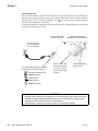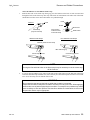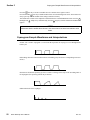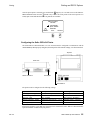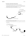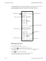
1
HANDHELD
CAPNOGRAPH/OXIMETER
User’s Manual
Model 710/715
October 12, 2000
Catalog No. 9110-23-05 / 9146-23-05
Novametrix Medical Systems Inc.
PO Box 690
5 Technology Drive
Wallingford, Connecticut, U.S.A. 06492
Revision History
30-Oct-98
Release, Rev. 00
15-Dec-98
Revision 01, R-N626
27-Jan-99
Revision 02
10-Dec-99
Revision 03, R-N719
6-Apr-00
Revision 04, R-N746
12-Oct-00
Revision 05, R-N835
Declaration of Conformity with European Union Directives
The authorized representative for Novametrix Equipment is:
European Compliance Services Limited
Oakdene House
Oak Road
Watchfield
Swindon, Wilts SN6 8TD
UK
Novametrix manufacturing facility is certified to ISO 9001 and EN46001 (MDD93/42/EEC Annex II). Novametrix
Medical Systems Inc. products bear the “CE 0086” mark. The product is certified by Underwriter’s Laboratories (UL)
to bear the UL mark; and tested by TUV Rheinland to IEC601-1 / EN60601-1.
TIDAL WAVE Sp and CAPNOSTAT are registered trademarks and Y-Sensor, SuperBright and OxySnap are trademarks
of Novametrix Medical Systems Inc. Velcro is a registered trademark of Velcro USA, Inc. Cidex is a trademark of
Arbook, Inc. Nafion is a registered trademark of Dow Corning Corp. Models 710 and 715 are Year 2000 compliant.
Copyright 1998-2000 Novametrix Medical Systems Inc. This document contains information which is proprietary and
the property of Novametrix Medical Systems Inc., and may not be reproduced, stored in a retrieval system, translated,
transcribed or transmitted in any form, or by any means, without prior explicit written permission from Novametrix
Medical Systems Inc.
Rev. 05
TIDAL WAVE Sp User’s Manual
iii
iv TIDAL WAVE Sp User’s Manual
Rev. 05
Contents
General Description .....................................................................................................1
Indication for use .........................................................................................................1
Keypanel Controls and Indicators ...............................................................................1
Connections and Labeling ..........................................................................................4
Principle of operation ..................................................................................................5
Safety .............................................................................................................................7
Preparation for Use ......................................................................................................9
AC/Battery Operation ..................................................................................................9
Battery Status and Alerts ............................................................................................9
Battery Use and Options ...........................................................................................10
Configuration Menus .................................................................................................16
Sensors and Patient Connections ............................................................................21
Adapter Types Available ..........................................................................................21
Setting Adapter Type ................................................................................................21
Adapter Zero Procedure ............................................................................................22
CAPNOSTAT CO2 Sensor and Airway Adapter Setup .............................................24
SpO2 Sensors ..........................................................................................................27
Monitoring ...................................................................................................................41
Display of Data ..........................................................................................................41
Monitoring Mode .......................................................................................................41
Screen Displays ........................................................................................................42
Messages ..................................................................................................................44
Alerts .........................................................................................................................47
Setting Alert Limits ....................................................................................................47
Alert Audio .................................................................................................................49
Capnogram Sample Waveforms and Interpretations ................................................50
Reference Handbooks ..............................................................................................51
Printing and RS232 Options ......................................................................................53
Power and RS232 Serial Port Communications .......................................................53
Printing ......................................................................................................................54
Interpreting Printer Output .........................................................................................57
Maintenance ................................................................................................................61
Cleaning and Sterilization .........................................................................................61
Battery Maintenance .................................................................................................63
Maintenance Schedules ............................................................................................64
Specifications .............................................................................................................65
General .....................................................................................................................65
Capnograph ..............................................................................................................65
SpO2 Section ............................................................................................................66
Pulse Rate Section ....................................................................................................66
Monitor Specifications ...............................................................................................67
Additional Features ...................................................................................................67
Accessories ................................................................................................................69
Rev. 05
TIDAL WAVE Sp User’s Manual
v
Warranty ...................................................................................................................... 73
Service Policy ........................................................................................................... 74
vi TIDAL WAVE Sp User’s Manual
Rev. 05
Section 1
General Description
Indication for use
The Model 710 and Model 715 TIDAL WAVE Sp handheld, portable Capnometer/Oximeters are intended
to be used for monitoring end tidal CO2, respiration rate, functional oxygen saturation and pulse rate in
monitoring environments such as ventilatory support, emergency and anesthesia. The Model 715
incorporates a miniature vacuum pump to draw expired respiratory gases through the CAPNOSTAT CO2
Sensor using a sampling airway adapter and nasal cannula. TIDAL WAVE Sp is designed to monitor adult,
pediatric and neonatal patients. TIDAL WAVE Sp is not intended for any other purpose.
NOTE
Components of this product and its associated accessories which have patient contact are
free of latex.
Keypanel Controls and Indicators
Display screen
Page key
Alert key
Power key
Backlight key
Adapter key
Battery charge indicator
and LED
AC indicator
Alert LED
Controls
Power Key
Switches power on/off. Press the POWER key to place the unit into operate mode (ON) or to turn the unit
OFF. Refer to “AC/Battery Operation” on page 9.
With monitor ON, press and hold the POWER key to enter the MONITORING MODE selection menu.
Refer to “Monitoring Mode” on page 41 for more information.
Rev. 05
TIDAL WAVE Sp User’s Manual
1
Section 1
Keypanel Controls and Indicators
Page Key
Press to set display screen to Data Display, EtCO2 waveform, plethysmogram, EtCO2 trend, Respiration
trend or SpO2 trend.
Press and hold to enter the PRINT SELECTION menu. See “Printing” on page 54.
Alert Key
When pressed, will set the 2 minute silence (audible alerts muted for two minutes) and displays the SET
ALERTS menu. If the SET ALERTS menu is not needed, it will automatically disappear after 3 seconds.
For 2 minute silence, the
icon will illuminate for the duration. Press again to cancel.
Press and hold for 3 seconds to disable audible alerts, and the
icon will flash. Press and hold again to cancel.
The Alert Key LED will display the following:
•
•
•
Steady yellow: audio silenced for 2 min., no alert in progress.
Flashing yellow: audio silenced (no alert in progress).
Flashing red and yellow: alert in progress; audio is off or 2 minute silence.
Audible alerts may be permanently disabled from the Configuration menu. Refer to “Configuration
Menus” on page 16 for more information.
Adapter Key
Press to set adapter type: adult, neonatal or sampling.
Press and hold for 4 seconds to zero an adapter. See “Adapter Zero Procedure” on page 22 for more information.
Press to cancel Auto Power Off function.
Backlight Key
Press to turn backlight on/off, or press and hold to adjust contrast for up/down viewing angles and for
adjustment due to extreme temperature variations.
Indicators
Battery Alert Indicator
Illuminates when the unit is on battery power. Green; battery is fully charged, slow flashing yellow;
battery power is low (approximately 20 minutes of operation remains), Fast flashing red; battery is
exhausted (approximately 5 minutes of operation remains). The battery alert indicator is off when
external power is connected. Refer to “AC/Battery Operation” on page 9 for information on connecting
AC power and charging the battery.
AC Power Indicator
Illuminated green when the monitor is connected to an AC power source (e.g. the external power supply
(PN 9220-10), or the BaseStation (PN 6998-00), while powered by the external power supply).
2
TIDAL WAVE Sp User’s Manual
Rev. 05
General Description
Keypanel Controls and Indicators
Icons
The icons listed below may appear on the display screen when the TIDAL WAVE Sp is in use.
Alert Silence Icon
Audible alerts silenced.
2-Minute Silence Icon
Audible alert silenced for two minutes.
Alert Limits Disabled Icon
Alert limits disabled. Select ENABLED or DISABLED in the CONFIGURATION menu.
Airway Adapter Icon
Indicates adapter key.
Time/Date Icon
Set time/date. Press
from the CONFIGURATION menu to set time and date.
Backlight Icon
Indicates backlight key.
Trend Screen Icon
Displayed beside any Trend screen.
Temperature Icon
Sensor not up to temperature icon. Displayed when performing an adapter zero and the sensor is not at
operating temperature.
Waveform Icon
CO2 detected icon. Displayed when selecting an adapter zero and the monitor detects breaths.
Heart Icon
Pulse detected icon. Displayed when SpO2 sensor is attached to patient and the monitor detects a pulse.
Lung Icon
Breaths detected icon. Displayed when CAPNOSTAT CO2 sensor is attached to patient and breaths are detected.
Rev. 05
TIDAL WAVE Sp User’s Manual
3
Section 1
Connections and Labeling
Connections and Labeling
DB-9 SpO2 sensor connection
Endview
Model 710
Sampling system output
Endview
Model 715
Sampling system input
CO2 sensor connection
DC input
Rearview
Model 710/715
Sideview
Model 710/715
RS232 connection
and external power
input from BaseStation
Battery compartment
4
TIDAL WAVE Sp User’s Manual
Rev. 05
General Description
Principle of operation
Symbols
Patient isolation: Identifies connection as type BF
Attention: Consult manual for detailed information
Sampling System: Gas output
Sampling System: Gas input
DC input. Connect external power supply to this port. Use only Novametrix external power
supply, Catalogue number 9220-10.
Recyclable item. This symbol is found on the internal battery and should not concern the
common user. Refer to qualified service personnel when battery replacement is required.
Separate collection. Appropriate steps must be taken to ensure that spent batteries are
collected separately when disposed of. This symbol is found on the internal battery and
should not concern the common user. Refer to qualified service personnel when battery
replacement is required.
Principle of operation
CO2
TIDAL WAVE Sp uses the CAPNOSTAT CO2 sensor to measure CO2 by using the infrared absorbtion technique,
which has endured and evolved in the clinical setting for over two decades and remains the most popular and
versatile technique today.
The principle is based on the fact that CO2 molecules absorb infrared (IR) light energy of specific wavelengths,
with the amount of energy absorbed being directly related to the CO2 concentration. When an IR beam is passed
through a gas sample containing CO2, the electronic signal from the photodetector (which measures the remaining
light energy) can be obtained. This signal is then compared to the energy of the IR source and calibrated to
accurately reflect CO2 concentration in the sample. To calibrate, the photodetector’s response to a known
concentration of CO2 is stored at the factory in the monitor’s memory. A reference channel accounts for optical
changes in the sensor, allowing the system to remain in calibration without user intervention.
SpO2
The TIDAL WAVE Sp determines oxygen saturation using sensors that contain red and infrared (660 and 940
nanometer) light sources, called light emitting diodes (LEDs). The light energy from each LED is beamed through
a tissue sample—a pulsating vascular bed such as the patient’s finger or toe. The remaining light energy not
absorbed by the tissue sample reaches a photodiode light receptor in the sensor. Oxygen saturated blood absorbs
Rev. 05
TIDAL WAVE Sp User’s Manual
5
Section 1
Principle of operation
different amounts of light at each wavelength as compared to desaturated blood. Therefore, the amount
of light absorbed by the blood in each pulse can be used to calculate oxygen saturation.
The TIDAL WAVE Sp is calibrated to display “functional” saturation. This differs from the “fractional”
saturation value displayed by most co-oximeters. Functional saturation is defined as:
HbO2
Functional Saturation =
100 - (COHb + METHb)
HbO2 = Fractional Oxyhemoglobin
COHb = Carboxyhemoglobin
METHb = Methemoglobin
This can be considered to represent the amount of oxyhemoglobin as a percentage of the hemoglobin that
can be oxygenated. Dysfunctional hemoglobins (COHb and METHb) are not included in the
measurement of functional saturation.
Pulse Rate is calculated by measuring the time interval between peaks of the infrared light waveform.
The inverse of this measurement is displayed as pulse rate.
The oxygen saturation and pulse rate values are updated once each second. Presence of a pulse is
indicated visibly by a plethysmogram graphic display and audibly by a “beep,” when configured.
The TIDAL WAVE Sp must be used in conjunction with SuperBright™ Sensors. See “Accessories” on
page 69 for a list of available sensors and accessories.
6
TIDAL WAVE Sp User’s Manual
Rev. 05
Section 2
Safety
For maximum patient and operator safety, you must follow the following warnings and cautions.
WARNINGS
!
Indicates a potentially harmful condition that can lead to personal injury.
•
•
•
•
•
•
•
•
•
•
•
•
•
•
Rev. 05
Explosion Hazard: DO NOT use TIDAL WAVE Sp in the presence of flammable anesthetics. Use
of this instrument in such an environment may present an explosion hazard.
Electrical Shock Hazard: Always turn TIDAL WAVE Sp off and remove any external devices
before cleaning it. Refer servicing to qualified service personnel.
Failure of Operation: If the monitor fails to respond as described, do not use it until the situation
has been corrected by qualified personnel.
Do not operate TIDAL WAVE Sp if it appears to have been dropped or damaged.
Do not operate TIDAL WAVE Sp or its accessories when it is wet due to spills or condensation.
Never sterilize or immerse the monitor, sensor or accessories in liquids.
The monitor does not alert for NO RESPIRATION if the airway adapter is removed from the
CAPNOSTAT CO2 sensor.
Verify the “No Resp Timer” setting prior to use.
Do not position any sensor cable in a way that may cause entanglement or strangulation.
The TIDAL WAVE Sp is not intended to be used as a primary diagnostic apnea monitor and/or
recording device.
Patient Safety: Care should be exercised to assure continued peripheral perfusion distal to the
SpO2 sensor site after application.
Inspect the SpO2 sensor site often for adequate circulation - at least once every four hours. When
applying sensors take note of patient’s physiological condition. For example, burn patients may
exhibit more sensitivity to heat and pressure and therefore additional consideration such as more
frequent site checks may be appropriate.
Data Validity: As with all pulse oximeters, inaccurate SpO2 and Pulse Rate values may be caused by:
- Incorrect application or use of sensor;
- Significant levels of dysfunctional hemoglobin; carboxyhemoglobin or methemoglobin;
- Significant levels of indocyanine green, methylene blue, or other intravascular dyes;
- Exposure to excessive illumination such as surgical lamps-especially those with a
xenon light source, or direct sunlight;
- Excessive patient movement;
- Venous pulsations;
- Electrosurgical interference.
The external battery charger should NOT be used to recharge the battery near or in close proximity
to patients and/or other medical equipment in operation. It is intended for use in service areas only
(i.e. nurses station, biomed lab, etc.).
TIDAL WAVE Sp User’s Manual
7
Section 2
•
Connection of an external device (e.g. printer or computer) to the RS232 serial port on the
BaseStation may compromise patient safety.
CAUTIONS
!
Indicates a condition that may lead to equipment damage or malfunction.
•
•
•
•
•
•
•
•
•
•
•
•
•
•
•
Federal (U.S.A.) law restricts this device to sale, distribution, or use by or on the order of a
licensed medical practitioner.
Use only an external power supply approved by Novametrix for use with this device. Use of any
other power supply may damage the TIDAL WAVE Sp and void the warranty.
Do not operate TIDAL WAVE Sp or its accessories when it is wet due to spills or condensation.
Do not operate TIDAL WAVE Sp if it appears to have been dropped or damaged.
Keep TIDAL WAVE Sp and its accessories clean.
Inspect the integrity of the TIDAL WAVE Sp and its accessories prior to use.
Never sterilize or immerse the monitor, sensor or accessories in liquids.
Do not sterilize or immerse sensors except as directed in this manual.
Do not apply excessive tension to any sensor cable or pneumatic tubing.
Do not store the monitor or sensors at temperatures less than 14°F (-10°C) or above 131°F (55°C).
Do not operate the monitor or sensors at temperatures below 50°F (10°C) or above 104°F (40°C).
If a Single Patient Use Sampling Adapter becomes occluded, replace and discard the adapter.
It is recommended that the CAPNOSTAT CO2 sensor be removed from the circuit whenever an
aerosolized medication is delivered. This is due to the increased viscosity of the medications
which may contaminate the sensor windows, causing the sensor to fail prematurely.
Where electromagnetic devices (i.e. electrocautery) are used, patient monitoring may be
interrupted due to electromagnetic interference. Electromagnetic fields up to 3V/m will not
adversely affect system performance.
Refer servicing to qualified personnel.
NOTES
Indicates points of particular interest or emphasis for more efficient or convenient operation.
•
•
•
•
•
8
The TIDAL WAVE Sp monitor is intended for operation with Novametrix Single Patient Use
airway adapters.
Operating the TIDAL WAVE Sp below 50°F (10°C) will result in longer warm-up time and reduce
battery life.
Components of this product and its associated accessories which have patient contact are free of
latex.
Certain rebreathing circuits, or the presence of artifacts such as cardiogenic oscillations, may
cause TIDAL WAVE Sp to react to non-respiratory CO2 fluctuations as if they were breaths. This
condition affects only the RESP numerical displays; the capnogram display continues to provide
an accurate picture of the CO2 waveform.
After the life cycle of our equipment and all accessories has been met, disposal of the equipment
should be accomplished following the national requirements. Contact the local Novametrix
representative for questions concerning disposal.
TIDAL WAVE Sp User’s Manual
Rev. 05
Section 3
Preparation for Use
The TIDAL WAVE Sp can be powered four ways: from seven “AA” disposable lithium batteries, a
rechargeable NiMH battery, the 9220-10 external power supply or the 6998-00 BaseStation combined
with the external power supply, all available from Novametrix.
AC/Battery Operation
Press the
POWER key to place the unit into operate mode (ON) or to turn the unit OFF. The status
of the unit is dependent upon both the
Power key and the power source.
The monitor can operate for up to 4.5 hours while powered from a fully charged internal battery (4 hours
when using sampling pump, Model 715). The battery is charging when the monitor is powered through
its DC input and the keypanel
icon is green. The battery will charge even if the monitor is off. Power
to the DC input is supplied by the external power supply (Cat. No. 9220-10) with or without the optional
BaseStation (Cat. No. 6998-00).
Rechargeable and disposable battery capacity is shown in the table titled, “Battery Life and Recharge
Times” on page 14. Times may be reduced in colder temperatures or with the sampling adapter; operation
with the backlight off may slightly increase these times.
Battery Status and Alerts
When the monitor is operating on battery power, and the battery is sufficiently charged, the battery icon
LED
on the keypanel will be green. The battery level is reflected on the battery icon by different
colors (for example, battery fully charged: green, battery low: flashing yellow).
The
LED on the keypanel flashes red when the monitor is powered by its internal battery and
approximately 5 minutes remain. The monitor will sound an audible alert, then when the battery is depleted,
turn itself off. This alert can only be silenced by connecting the external supply or turning the monitor off.
The NiMH battery pack should be replaced, or the TIDAL WAVE Sp BaseStation (Cat. No. 6998-00) or
external power supply (Cat. No. 9220-10) should be connected to recharge the battery (rechargeable
batteries only) and power the monitor. See “Battery Life and Recharge Times” on page 14.
NOTE
When the battery is low (red blinking battery LED
on keypanel) the monitor has shut
down CO2 and SpO2 functions. Connect to AC power as soon as possible.
Rev. 05
TIDAL WAVE Sp User’s Manual
9
Section 3
Battery Use and Options
NOTE
• The battery life indicator may not reflect the true battery status upon power-up for
approximately 30 seconds.
• The battery life indicator is inactive when the monitor is powered by the BaseStation or
the external power supply.
Battery Use and Options
Removing and Installing the Battery
Grasp the finger grips on each end of the battery cover. Squeeze together and pull so that the cover opens
to reveal the internal battery (the cover is hinged on the bottom of the case). Remove the battery from the
monitor.
Finger grip
Power jack
Interface connector
WARNING: Do NOT connect to any device not
approved by Novametrix
Hinged side
Battery cover
The battery is keyed so that it can be installed in only one way (see illustration inside battery
compartment). The contacts should go in first and be located toward the top left of the monitor when
inserting. Make certain the battery cover is properly closed before operating the monitor.
10
TIDAL WAVE Sp User’s Manual
Rev. 05
Preparation for Use
Battery Use and Options
Rechargeable Batteries
The NiMH rechargeable battery pack (Cat. No. 400043) can be used to power the TIDAL WAVE Sp for
approximately 4.5 hours of continuous operation (4 hours when using sampling pump, Model 715).
Optional
Rechargeable battery,
(NiMH 7.2 vdc)
NOTE
• Refer to the instruction sheet packaged with the rechargeable battery for complete
operating instructions.
To charge a rechargeable battery while in the monitor:
External Power Supply
Alternatively, plug the external power supply directly into the DC power jack on the side of the monitor,
and connect a hospital-grade line cord to an AC source. The AC icon
will illuminate green and the
battery will charge in approximately 5.5 hours. If the monitor has been stored with the battery installed
for thirty (30) days or more, charge the battery for 24 hours prior to use.
DC input
Connect line cord
(Cat. No. 600075)
External power supply
(Cat. No. 9220-10)
CAUTION
•
•
Use only Novametrix supplied devices when connecting to the power input jacks on the
TIDAL WAVE Sp or on the BaseStation.
Do not attempt to use the adapter for the external battery charger for this function.
NOTE
•
•
Rev. 05
When powered by the external power supply, the TIDAL WAVE Sp will not overcharge a
rechargeable battery.
The external power supply has a universal power input. The IEC 320 input receptacle for
line cord connection allows compatibility with every country’s voltage and frequency
requirements.
TIDAL WAVE Sp User’s Manual
11
Section 3
Battery Use and Options
Optional BaseStation
Power for the BaseStation is supplied by an external power supply (PN 9220-10) or the internal battery.
When the power supply is properly connected to the BaseStation and a monitor is placed within the
station the green, “In Use” LED will illuminate. The
icon on the monitor will also illuminate
indicating that external power is connected.
Connect the external power supply jack to the monitor and connect a hospital-grade line cord from the
external power supply to an AC source.
External power supply
(Cat. No. 9220-10)
Connect line cord
IEC 320 receptacle
(Cat. No. 600075)
The 9220-10 Power Supply is approved
by the following regulatory agencies:
: Canadian Standards Assoc.
Monitor in BaseStation
(BaseStation Cat. No. 6998-00)
DC input
Green “In Use” LED
illuminates indicating
a monitor is in place
and the power supply
is active
Illuminates indicating
external power
: SEMKO (Sweden)
V
D E
: VDE (Germany)
FI
: FINKO (Finland)
D : DEMKO (Denmark)
CAUTION
•
•
12
Although other connectors may physically fit, do not attempt to connect any device other
than power supplies approved by Novametrix for use with this device. Doing so may
damage the TIDAL WAVE Sp and will void the warranty.
Never sterilize or immerse the monitor, sensor or accessories in liquids.
TIDAL WAVE Sp User’s Manual
Rev. 05
Preparation for Use
Battery Use and Options
Charging NiMH Rechargeable Battery with External Charger
In a non-patient area, connect the adapter to an AC source, then plug the adapter jack into the charger.
Remove the battery from the TIDAL WAVE Sp and insert it into the external charger. The battery will be
fully charged in approximately 4.5 hours. The external charger is for use with the NiMH rechargeable
battery pack (Cat. No. 400043) only. Refer to the instructions supplied with the charger for additional
information.
NiMH Rechargeable Battery
(Cat. No. 400043)
Connect adapter
Battery is keyed
to fit into slot in
only one direction
Connect line cord
WARNING
•
The external battery charger should NOT be used to recharge the battery near or in close
proximity to patients and/or other medical equipment in operation. It is intended for use in
service areas only (i.e. nurses station, biomed lab, etc.).
NOTE
•
•
•
•
Rev. 05
With a new battery, or a battery that has not been used for 30 days or more, charge the
battery for 24 hours prior to use.
When powered by the external power supply or the BaseStation, the TIDAL WAVE Sp will
not overcharge a rechargeable battery.
The monitor may not operate on battery power if the battery is not sufficiently charged.
Dispose of batteries in accordance with local laws.
TIDAL WAVE Sp User’s Manual
13
Section 3
Battery Use and Options
AA Lithium Batteries
To power TIDAL WAVE Sp from AA lithium batteries, insert seven disposable batteries (Energizer L91
or equivalent) into the optional Battery Case (Cat. No. 6862-00) following the polarity markings on the
Battery Case.
Standard
AA lithium batteries
(7 ea. - disposable)
WARNING
•
•
Batteries can explode, leak or catch on fire if heated or exposed to fire or high
temperatures.
Do not mix battery types (e.g. disposable and rechargeable AA batteries).
Battery Life and Recharge Times
Configuring the monitor to turn off unused functions will result in longer battery life. The following table
lists battery operation times with Sampling pump off (Model 710/715), Sampling pump on (Model 715)
for each mode: CO2/SpO2, CO2, or SpO2. See “Monitoring Mode” on page 41.
Power source - Approximate Monitoring Times
Configuration
Rechargeable NiMH battery
AA lithium batteries
Model 710/715 - CO2/SpO2
4.5 hours
4.0 hours
Model 715 - CO2 Sampling/SpO2
4.0 hours
3.5 hours
Model 710/715 - CO2 only
4.5 hours
4.0 hours
Model 715 - CO2 Sampling only
4.0 hours
3.5 hours
Model 710/715 - SpO2 only
7.0 hours
6.5 hours
Recharge Time:
External charger w/adapter
4.5 hours
n/a
5.5 hours (in monitor)
n/a
Recharge Time:
External power supply or
External power supply/BaseStation
NOTE
Excessive alerting reduces battery life when operating on battery power.
14
TIDAL WAVE Sp User’s Manual
Rev. 05
Preparation for Use
Battery Use and Options
Automatic Power Off Feature
The automatic power off feature is included to conserve battery power in the event of an unintentional
power up of the monitor. This option will shut the monitor off if there is no CO2 breath or pulse detection
after 5 minutes from when the unit powers on, or after 20 minutes of no monitoring (no breath or pulse
detected and no alert conditions). After the 5 or 20 minutes has elapsed, an AUTO POWER OFF IN
X:XX message will appear on the screen and the timer (X:XX) will count down from one minute to zero.
Pressing the adapter key, or detection of a CO2 breath or pulse will cancel the shutdown, otherwise the
unit will shut off.
Long Term Storage
If the monitor has not been used or powered by the external power supply for an extended time* (3 months
or more) allow the battery to charge before use or replace the battery with a fully charged battery and
continue monitoring. The monitor may not power up on battery power if the battery is not sufficiently
charged. Refer to “Battery Life and Recharge Times” on page 14.
NOTE
• New batteries, or batteries stored for extended periods of time may need to be fully
charged and discharged up to five (5) times before performing at full capacity.
• With a new battery, or a battery that has not been used for 30 days, charge the battery
for 24 hours prior to use.
Serial Communications/Power Interface Connector
Located on the enclosure rear is a six pin modular contact which provides an RS232 interface as well as
a power input for unit operation and battery charging when connected to Novametrix accessories. This
connector meets the patient safety requirements of the following agencies: IEC 601-1, UL544.
The BaseStation (Cat. No. 6998-00) is an optional accessory onto which Novametrix hand-held monitors can
be placed, providing a platform for communication support between the monitor and a host computer or
printer. The BaseStation is meant for table-top (horizontal), not pole-mounted (vertical) applications and can
be used anywhere the TIDAL WAVE Sp monitor is used; including but not limited to the sleep lab, ICU,
anesthesia, post anesthesia, emergency department, respiratory care, home care, and pre-hospital emergency.
The BaseStation provides RS232 serial communications as supported by the monitor, with or without the
external power supply connected. In addition, the BaseStation is capable of providing power to charge a
rechargeable battery inside the monitor when used with the external power supply.
*The internal battery will slowly discharge over long periods of non-use.
Rev. 05
TIDAL WAVE Sp User’s Manual
15
Section 3
Configuration Menus
Configuration Menus
CONFIGURATION menus are provided on the TIDAL WAVE Sp to allow customizing of various
settings. To access the CONFIGURATION menus, press and hold the
key, then simultaneously press
the
key until the first CONFIGURATION menu is displayed. Press the
PAGE key to move
through the menus. The
SELECT key moves the arrow pointer; the parameter chosen will flash. Press
the
EXIT key at any time to return to monitoring mode (selections will be saved).
**
**Press SELECT to scroll down to INST in the EtCO2 Averaging menu.
16
TIDAL WAVE Sp User’s Manual
Rev. 05
Preparation for Use
Configuration Menus
Displays selected setting
Changes settings of
selected item
Selects screen
Press to set time/date
Press to exit
NOTE
If an attempt is made to change CO2 units after data has been collected, a message warning
that trend memory will be erased is displayed. To change units and erase trends, press the
OK key to continue, then the
EXIT key to confirm and exit.
Configuration Settings
The CONFIGURATION menus can be programmed by the user to customize the TIDAL WAVE Sp. Any
changes made will be retained when the monitor is turned off. NOTE: To reset the monitor to its factory
default settings: with the monitor off, press and hold the
key and the
key, then press the
key
to turn the monitor on.
Options are listed below with descriptions following:
Rev. 05
Parameter
Settings and Description
Factory Default
GAS COMPENSATION
Room Air
Room air, O2 > 60%, N2O > 60%
Use this setting to enter the gas composition in order
to compensate the CO2 measurement for gas density.
Any setting other than the default will cause the monitor to display “O2” or “O2 N2O” on the screen beside
the respiration value.
CO2 WAVEFORM SCALE
Small, Medium, Large
Select the desired size of the capnogram waveform.
Medium
CO2 WAVEFORM SPEED
Slow, Fast, Medium
Select the desired speed of the capnogram waveform.
Medium
NO RESP TIMER
20 sec., 40 sec., 60 sec.
Alert setting activates if the end tidal CO2 portion of
the monitor cannot detect regular breaths for periods
longer than 10 seconds.
20 sec.
TIDAL WAVE Sp User’s Manual
17
Section 3
18
Configuration Menus
CO2 UNITS
mmHg, kPa, %
Select the desired units for both the capnogram and
ETCO2 values. Note that changing the CO2 units in
the Configuration menu will result in a loss of all
stored data. The message “WARNING: CHANGING
CO2 UNITS ERASES STORED TRENDS” will
display. Press CANCEL
, or press the
OK key
to acknowledge the warning, and return to the CO2
UNITS menu. Press the
Adapter key to EXIT
mmHg
ALERT VOLUME
Disabled, Low, High
Select the desired volume of audible alerts. Note that
care should be taken to set the volume level above
ambient noise levels.
High
RS232 INTERFACE
NOVACOMM
NOVACOMM (used when connected to an external
PC with optional software), SEIKO 414 (used when
connected to the Seiko DPU-414 Thermal Printer),
RESERVED 1, and RESERVED 2 (Novametrix use).
WAVEFORM FILL
Unfilled, Filled
Select the desired appearance of the capnogram
waveform.
Unfilled
ETCO2 AVERAGING
1 Breath, 10 sec, 20 sec, INST
Select the interval from which the displayed value of
end tidal CO2 (ETCO2) is calculated.
10 sec
SpO2 AVERAGING
2 sec, 8 sec
Select the interval from which the displayed value of
oxygen saturation (SpO2) is calculated.
8 sec
ALERT LIMITS
Disabled
Disabled, Enabled
Enable or disable the Alert Limits function. Select the
desired high and low alert limits by exiting the CONFIGURATION menu and pressing the
Alert key.
PULSE BEEP VOLUME
Off, Low, High
Select the desired volume of pulse beep. Note that
care should be taken to set the volume level above
ambient noise levels.
OFF
RESP TREND SCALE
Small, Medium, Large
Select the desired size of the respiration trend
waveform.
Medium
AUTO POWER OFF
Enabled, Disabled
Selects automatic shut off of unit if no signal is
detected, to conserve battery power.
Enabled
TIDAL WAVE Sp User’s Manual
Rev. 05
Preparation for Use
Configuration Menus
The following parameters are accessed by pressing
Press
to move through the menus.
SET TIME AND DATE
Press the 24 hour format. Day number, short month
name, year (e.g. 14-DEC-1998)
(From within the CONFIGURATION Menu, press
key to access this screen). Select to program or
change the time and date. The format is “TIME:
HH:MM DDmmmYYYY” where HH=hours from
00-23, MM=minutes from 00-59, DD=days of the
month from 01-31, mmm=month, YYYY=year
(using all four digits).
LANGUAGE
All languages available in the current software
release are listed in this menu.
SOFTWARE REVISIONS
MAIN PROGRAM
Date, time and version of 710/715 software currently
loaded in to this unit.
CAPNOSTAT SERIAL #
Serial number of CAPNOSTAT CO2 sensor attached
to this monitor.
Verifying monitor accuracy with calibration gas should
be performed only by qualified service personnel.
VERIFY ACCURACY
Rev. 05
from one of the previous Configuration menus.
TIDAL WAVE Sp User’s Manual
19
Section 3
Configuration Menus
[This page intentionally blank.]
20
TIDAL WAVE Sp User’s Manual
Rev. 05
Section 4
Sensors and Patient Connections
Adapter Types Available
Pediatric/Adult Single Patient Use Airway Adapter
(Catalog No. 6063):
• For intubated patients with endotracheal tube diameters greater than
4 mm. Adds approximately 5 cc of deadspace;
• For connecting to anesthesia, non-rebreathing, or BIPAP/CPAP masks
for non-intubated patients.
Pediatric/Adult Single Patient Use Airway Adapter with mouthpiece
(Catalog No. 6421):
• For point-of-care monitoring of pediatric or adult patients. Adds
approximately 8 cc of deadspace.
Neonatal/Pediatric Single Patient Use Airway Adapter
(Catalog No. 6312):
• For intubated patients with endotracheal tube diameters no more than
4 mm. Adds approximately .5 cc of deadspace.
Sampling Adapter, Single Patient Use (Catalog No. 8954):
• For monitoring non-intubated patients with nasal cannulas.
• For monitoring pediatric tracheostomy patients.
Setting Adapter Type
The TIDAL WAVE Sp uses three types of disposable, Single Patient Use adapters: Adult/Pediatric,
Neonatal and Sampling. Press the
Adapter key to access the adapter menu, then the
SELECT key
to move the arrow pointer to the correct type. The selected adapter type is displayed in the message area
in the center of the display screen.
Rev. 05
TIDAL WAVE Sp User’s Manual
21
Section 4
Adapter Zero Procedure
If the adapter type placed on the CAPNOSTAT CO2 sensor does not match the currently selected adapter
type, a “CHECK ADAPTER” message will appear. If the adapter type is correct, see the “Adapter Zero
Procedure” on page 22.
Adapter Zero Procedure
An adapter zero allows the monitor to accommodate the optical characteristics of each different type of
adapter. Before zeroing, verify the selected adapter type is correct, and the adapter setting is correct.
NOTE
• This procedure is to be performed with a new unused single patient use adapter only!
Perform this procedure only if the CHECK ADAPTER message persists, or if deemed
necessary by qualified personnel.
• Do not perform this procedure while the CAPNO WARMING (Model 710) message is
displayed.
• Do not perform this procedure while the adapter is connected to a breathing circuit,
mouthpiece or mask on a patient.
• The pediatric/adult, neonatal and sampling adapters must be zeroed independently
(ensure that the proper adapter type is selected).
1.
Attach the selected adapter type to the CAPNOSTAT CO2 sensor. Select the adapter type (pediatric/adult,
neonatal or sampling) to be zeroed by pressing the
Adapter key to access the adapter menu. Press the
SELECT key to move the arrow pointer to the correct type of adapter and confirm the selection with
the
EXIT key.
2.
Press and hold the
Adapter key for five seconds to enter the zero menu.
WARNING
• Zeroing with the incorrect adapter type will cause incorrect readings.
• Zeroing the wrong adapter type on the wrong adapter setting will cause incorrect
readings.
• Do not zero the CAPNOSTAT CO2 sensor without a single patient use adapter attached.
Incorrect readings or no readings will result.
22
TIDAL WAVE Sp User’s Manual
Rev. 05
Sensors and Patient Connections
Adapter Zero Procedure
3.
With all sources of CO2 away from the adapter (including the patient’s - and your own - exhaled breath),
press the
ZERO key to begin the procedure or
CANCEL to exit.
NOTE
• If breaths are detected while attempting to zero the adapter, the
icon will display
and the zero menu will be exited automatically (remove the CO2 source, wait 15 seconds
and repeat the procedure from step 1).
• If the sensor is not at the proper temperature, the icon will display and the zero menu
will be exited automatically (wait 15 seconds and repeat the procedure from step 1).
• The TIDAL WAVE Sp will return to monitor mode automatically when the procedure is
complete.
• When SAMPLING has been selected from the ADAPTER menu, the sampling pump will
turn on when the CAPNOSTAT CO2 sensor is snapped onto the sampling adapter.
• When zeroing the sampling adapter, place the cannula away from all sources of CO2
including patient and operator breath, and ventilator exhaust valves. Verify the integrity
of all pneumatic connections.
Rev. 05
TIDAL WAVE Sp User’s Manual
23
Section 4
CAPNOSTAT CO2 Sensor and Airway Adapter Setup
CAPNOSTAT CO2 Sensor and Airway Adapter Setup
Patients requiring mechanical ventilation:
1.
Select a new Single Patient Use airway adapter.
(Pediatric/Adult - Cat. No. 6063 for ET tube size greater than 4.0 mm - see Fig. 1)
(Neonatal Cat. No. 6312 for ET tube size 4.0 mm or less, see Fig. 2)
Verify that the windows are clean and dry. Place the airway adapter in the patient's ventilator circuit. It
should be positioned between the ET tube elbow and the circuit "wye" with its window in a vertical position.
NOTE: In a pediatric or neonatal ventilator's circuit the elbow may not be present (Fig. 2).
2.
Be sure the airway adapter is positioned vertically and located so that patient secretions and condensate
water will flow AWAY from the adapter's windows, not through or into it.
3.
Snap the CAPNOSTAT CO2 sensor onto the airway adapter.
4.
Capnogram (CO2 waveform) or EtCO2 trend, EtCO2 values, and respiratory rate should be displayed on
the monitor.
(Fig. 1) Pediatric/Adult Single Patient Use airway adapter Cat. No. 6063
CAPNOSTAT
CO2 sensor
Wye
Elbow
Window
Patient connector
pediatric/adult
(Fig. 2) Neonatal Single Patient Use airway adapter Cat. No. 6312
CAPNOSTAT
CO2 sensor
Window
Patient connector
neonatal
24
TIDAL WAVE Sp User’s Manual
Rev. 05
CAPNOSTAT CO2 Sensor and Airway Adapter Setup
Sensors and Patient Connections
Spontaneously Breathing, Non-Intubated Patients
Mouthpiece:
1.
Select an airway adapter with mouthpiece (Cat. No. 6421, Fig. 3)
2.
Snap the CAPNOSTAT CO2 sensor onto the airway adapter.
3.
Instruct the patient to breath normally through his/her mouth while keeping a tight seal around the
mouthpiece.
NOTE: It has been reported in the literature that the presence of a mouthpiece may alter a patient's
breathing pattern. This usually has a minor impact on EtCO2.
(Fig. 3) Pediatric/adult with mouthpiece Cat. No. 6421
Window
Mask:
1.
Select a new Single Patient Use airway adapter (Pediatric/Adult Cat. No. 6063).
2.
Place the adapter onto a mask with a 22 mm connector (Fig. 4)
3.
Place the mask on the patient's face and instruct him/her to breath normally.
NOTE: If the patient requires low flow oxygen therapy it may be provided by placing the mask over the
nasal cannula. This will have a minimal effect on EtCO2 measurements.
(Fig. 4) Pediatric/Adult with Mask
Mask
22mm connector
CAPNOSTAT
CO2 sensor
Pediatric/Adult Single Patient
Use airway adapter
Sidestream Sampling (Model 715)
The Single Patient Use Sampling Airway Adapter (Cat. No. 8954) should be used in conjunction with a
nasal sampling cannula to monitor non-intubated patients.
Rev. 05
1.
Select a new Single Patient Use sampling adapter.
2.
Align the arrow on the bottom of the sampling adapter with the arrow on the bottom of the CAPNOSTAT
CO2 sensor and press the sensor and adapter together until they “click.”
TIDAL WAVE Sp User’s Manual
25
Section 4
CAPNOSTAT CO2 Sensor and Airway Adapter Setup
3.
Connect the nasal cannula/sampling adapter assembly to the Sampling Inlet
of the monitor.
Cat. No.
port located on the end
Cannula Type
8955
Nasal CO2 Sampling Cannula—Adult
8956
Nasal CO2 Sampling Cannula—Pediatric
8957
Nasal CO2 Sampling and O2 Delivery Cannula—Adult
8958
Nasal CO2 Sampling and O2 Delivery Cannula—Pediatric
CAPNOSTAT CO2 sensor
Nasal CO2 cannula/adapter assembly
(Cat. No. 8955, 8956
8957, or 8958)
4.
Ensure that the unit is in sampling mode:
a. Press the
b. Use the
c. Press the
26
Sampling adapter
(To monitor sampling
inlet,
)
Adapter key to set adapter type.
SELECT key until the arrow points to SAMPLING.
EXIT key to select SAMPLING.
5.
When SAMPLING has been selected from the ADAPTER menu, the sampling pump will turn on when
the CAPNOSTAT CO2 sensor is snapped onto the adapter. The sampling adapter requires a zero when
the monitor displays “CHECK ADAPTER”. To perform a zero, refer to “Adapter Zero Procedure” on
page 22.
6.
If using a Nasal CO2 Sampling and O2 Delivery Cannula, attach the O2 tubing to the administration
device and set the device to the prescribed O2 setting.
TIDAL WAVE Sp User’s Manual
Rev. 05
Sensors and Patient Connections
SpO2 Sensors
7.
Position the cannula on the patient.
Insert the cannula tips into the nostrils, pass the cannula tubing over the ears, then slide the retaining
sleeve up the tubing toward the neck to a comfortable fit under the chin.
8.
Check that the connections have been made properly by examining the CO2 waveform (capnogram) on
the monitor display.
NOTE
• If possible, position the Sampling Adapter with its windows in a vertical, and NOT a
horizontal position; this helps keep moisture from “pooling” on the windows.
• To prevent “rain-out” and moisture from draining into the Sampling Adapter, do NOT place
the Sampling Adapter in a gravity dependent position.
• If a Single Patient Use Sampling Adapter becomes occluded, replace and discard the
adapter.
SpO2 Sensors
CAUTION
Connect only Novametrix SpO2 sensor extension cables and/or SuperBright™ SpO2 sensors
to the TIDAL WAVE Sp. Do not use other SpO2 sensors or accessories with TIDAL WAVE Sp.
Before connecting to the patient or to the monitor, ensure that sensor extension cables and/
or sensors are physically intact, with no broken, frayed or damaged components.
1.
Plug the connector into the end panel SpO2 sensor input. The sensor connector is keyed to fit into the
input in only one direction.
Model 710
SuperBright
series DB-9 connector
Model 715
The connector clicks into place when properly seated. Sensors may be connected or removed whether or
not the monitor is turned on.
Rev. 05
TIDAL WAVE Sp User’s Manual
27
Section 4
SpO2 Sensors
Finger Sensor
The reusable Finger Sensor is intended for adult or appropriate size pediatric fingers and is not designed
for neonatal applications.
Finger sensor
1.
Gently squeeze the grips at the rear of the sensor (indicated by arrows below).
Placement guide
2.
Cable exits above finger
Position fingertip against placement guide with fingernail toward the red light.
Do not position the finger so as to protrude past the placement guide.
3.
Release the finger grips.
WARNING
Inspect the site often for adequate circulation—at least once every four hours. When applying
sensors take note of patient’s physiological condition. For example, burn patients may exhibit
more sensitivity to heat and pressure and therefore additional consideration such as more
frequent site checks may be appropriate.
4.
28
To remove sensor, gently squeeze grips and slide the sensor from the finger.
TIDAL WAVE Sp User’s Manual
Rev. 05
Sensors and Patient Connections
SpO2 Sensors
CAUTION
Overstretching the pulse oximeter finger sensor can damage the sensor and potentially affect
pulse oximeter readings. Do not stretch the finger sensor open beyond the limit for which it
was designed. Overstretching can be prevented: avoid opening the sensor by any means
other than squeezing the grips; DO NOT force the sensor onto large objects such as a bedrail.
Finger Sensor Quick Check
1.
Is “SPO2 PRB OFF PAT” displayed when the sensor is connected to the monitor but not applied to the
patient?
2.
Apply the sensor to your index finger. Are reasonable SpO2 and pulse rate values displayed?
3.
A YES to BOTH #1 and #2 indicates that the sensor is OK. Apply the sensor to the patient as instructed
above. The quick check is also a functional test of the extension cable.
Y-Sensor™
The reusable Y-Sensor is a flexible sensor designed for use on any patient. It is secured to the patient
using a Y-Strip tape, foam wrap, or ear clip (see below).
Y-Sensor
The Y-Sensor center strip is not a functional part of the sensor. Its twofold purpose is to aid in the
placement of the sensor into the Y-Strip or other securing system and to keep the distance between the
sensor heads to no more than 25 mm. The center strip may be removed (carefully cut away) if the distance
between the sensor heads needs to be reduced to less than 25 mm.
Sensor heads
Center strip
Strip may be removed
Rev. 05
TIDAL WAVE Sp User’s Manual
29
Section 4
SpO2 Sensors
Y-Sensor Application using Y-Strip Tapes or Foam Wrap
Select a Y-Strip or foam wrap based on the patient type and intended sensor location.
Wrap Style Tapes:
Y-Strip tapes are available in two color coded sizes: 25 mm tapes have
green liners, and 20 mm tapes have blue liners. The size refers to the
distance between the holes in the tape.
• Catalog No. 8828: 20mm (blue) neonatal foot, hand, pediatric toe, finger
• Catalog No. 8829: 25mm (green) neonatal foot, hand
Finger Style Tapes:
• Catalog No. 8831: 20mm (blue) pediatric finger, adult finger
• Catalog No. 8832: 25mm (green) adult finger
Non-Adhesive Foam Wraps:
• Catalog No. 8836, Large: adult/pediatric finger, neonatal/pediatric foot
or hand
• Catalog No. 8943, Small: neonatal foot or hand, pediatric toe or finger
Adhesive Foam Wraps:
• Catalog No. 6929, Large: adult/pediatric finger, neonatal/pediatric foot
or hand
• Catalog No. 6968, Small: neonatal foot or hand, pediatric toe or finger
To use the Y-Strip tapes:
1.
Remove the portion of the release liner containing the holes.
Remove release liners with holes
Wrap style tape
30
TIDAL WAVE Sp User’s Manual
Finger style tape
Rev. 05
Sensors and Patient Connections
SpO2 Sensors
2.
(Omit this step if using the 25 mm Y-Strip tape.)
If using the 20 mm Y-Strip tape, carefully remove the Y-Sensor center strip using a pair of scissors or a
sharp blade.
Strip removed
The center strip does not effect sensor operation; its purpose is to aid putting the sensor into the 25 mm
tape and to keep the distance between the sensor heads at 25 mm.
3.
Press the “button” on the back of each sensor head through a hole in the tape.
Press in from the sticky side of the tape. The tape will stretch to fit the sensor button.
Y-Sensor placed on Y-Strip tape
Liner this
Side (top)
Head
Y-Strip tape
Cross section
Button
4.
Remove the remaining release liner(s) if applicable and apply the sensor/tape to the patient.
Make certain that the sensor heads are directly opposite each other through the tissue. This prevents the
sensor from being placed on a site too thick for proper operation.
Position the sensor so that the tape does not extend over the space between the fingers or toes to insure
that there will be no light transmission through this space.
5.
Rev. 05
To maximize sensor life, secure the cable along the limb with tape as shown in the following illustrations.
TIDAL WAVE Sp User’s Manual
31
Section 4
SpO2 Sensors
Leave slack in the wires between the tape and the sensor.
Adult/pediatric finger
Neonatal hand
Neonatal/pediatric foot
Pediatric toe
WARNING
Do not wrap the tape around the limb so tightly that circulation is restricted.
Inspect the site often for adequate circulation—at least once every four hours. When applying
sensors take note of patient’s physiological condition. For example, burn patients may exhibit
more sensitivity to heat and pressure and therefore additional consideration such as more
frequent site checks may be appropriate.
32
TIDAL WAVE Sp User’s Manual
Rev. 05
Sensors and Patient Connections
SpO2 Sensors
To use the adhesive or non-adhesive foam wrap:
1.
With the blue side of the foam wrap facing up, press the buttons on the back of each Y-sensor head
through the holes in the foam wrap. The wrap will stretch to fit the buttons. The white side of the foam
should show two blue circles where the buttons were pushed through.
Head
Head
Y-Sensor:
Button
Blue Foam
Center Strip
(may be removed)
Cross section
of Sensor head
in the foam wrap
White Fabric
Non-Adhesive Foam Wraps
Adhesive Foam Wraps
Y-Sensor placed on foam wrap
Blue side facing up
Center strip removed
Center strip removed
NOTE
If using the first and third holes on the foam wrap it may be necessary to cut the center strip
off the Y-sensor.
2.
If you are using an adhesive wrap, remove both sides of the release liner. Face the blue side of the wrap
toward the skin and wrap around the site (Velcro tab may be removed and replaced to allow excess foam
to be cut as necessary). Secure with the Velcro® tab.
WARNING
Do not wrap the tape around the limb so tightly that circulation is restricted.
Inspect the site often for adequate circulation—at least once every four hours. When applying
sensors take note of patient’s physiological condition. For example, burn patients may exhibit
more sensitivity to heat and pressure and therefore additional consideration such as more
frequent site checks may be appropriate.
Rev. 05
TIDAL WAVE Sp User’s Manual
33
Section 4
SpO2 Sensors
3.
Ensure the sensor heads are directly opposite each other through the tissue. This prevents the sensor from
being placed on a site too thick for proper operation.
Neonatal hand
Neonatal/pediatric foot
Pediatric toe
Adult/pediatric finger
Adult toe
4.
Position the sensor so that the foam wrap does not extend over the spaces between the fingers or toes.
This ensures no light transmission through this space. To maximize sensor life, secure the cable along the
limb with tape as shown in the illustrations.
WARNING
Treat foam wrap in accordance with hospital protocol for single-patient use. Check site
regularly to ensure adequate circulation and proper sensor positioning.
34
TIDAL WAVE Sp User’s Manual
Rev. 05
Sensors and Patient Connections
SpO2 Sensors
Y-Sensor Application using Ear Clip
1.
Remove center strip from the Y-Sensor.
Sensor heads
Center strip (remove)
Strip removed
2.
Slide each Y-Sensor head into the ear clip‘s receptacles. The heads should face each other.
Sensor head
Ear clip receptacle
Squeeze here to apply
3.
Rev. 05
Gently squeeze the end of the ear clip (shown in diagram), and apply the sensor to the patient.
TIDAL WAVE Sp User’s Manual
35
Section 4
SpO2 Sensors
If a satisfactory reading cannot be obtained, rub the site and/or use adhesive dots for better response. The
adhesive dots (Catalog No. 8700) included with the ear clips will also help in preventing the ear clip from
falling off (during exercise for example).
Adult ear
Optional placements
WARNING
Inspect the site often for adequate circulation—at least once every four hours. When applying
sensors take note of patient’s physiological condition. For example, burn patients may exhibit
more sensitivity to heat and pressure and therefore additional consideration such as more
frequent site checks may be appropriate.
Y-Sensor Quick Check
36
1.
With the Y-Sensor connected to the monitor but not applied to patient, position the sensor heads so that
they face each other (the red light shines at the detector). Is “SPO2 PRB OFF PAT ” displayed?
2.
Tape the Y-Sensor to your index finger. Does the monitor show reasonable SpO2 and pulse rate values?
3.
A YES to BOTH #1 and #2 indicates that the sensor is working properly. Apply the sensor to the patient
as instructed above. The quick check is also a functional test of the extension cable.
TIDAL WAVE Sp User’s Manual
Rev. 05
Sensors and Patient Connections
SpO2 Sensors
Single Patient Use SpO2 Sensors
Select a Y-Strip or foam wrap based on the patient type and intended sensor location.
Single Patient Use Pediatric/Adult Sensor (Catalog No. 6455):
• The single patient use SpO2 sensor can be used when monitoring adult or
pediatric patients with Novametrix Pulse Oximeters (SuperBright
series).
Single Patient Use Neonatal/Pediatric Sensor (Catalog No. 6480):
• The single patient use SpO2 sensor can be used when monitoring
neonatal or pediatric patients with Novametrix Pulse Oximeters
(SuperBright series).
WARNING
Use the Single Patient Use sensor and DB-9 extension cable only with Novametrix
SuperBright compatible pulse oximeters. Use with any other device may result in equipment
damage or patient injury.
CAUTION
These SpO2 sensors are intended for single patient use. The sensors can be reapplied to
various sites on the same patient but should not be used on multiple patients. Do not attempt
to clean or disinfect the sensor, as system performance will be compromised.
NOTE
The Single Patient Use sensor should be discarded if sensor integrity becomes questionable.
Rev. 05
TIDAL WAVE Sp User’s Manual
37
Section 4
SpO2 Sensors
Single Patient Use SpO2 Sensor Application
1.
Select the appropriate size sensor based on the patient type. Connect the DB-9 connector to the TIDAL
WAVE Sp rear panel connector.
Pediatric/adult sensor
Adult toe
Adult finger
Neonatal/pediatric sensor
Neonatal hand
Neonatal foot
2.
Pediatric toe
To apply the sensor, place the blue side of the sensor wrap against the skin, wrap it around the site and
secure with Velcro* tab. The Velcro tab on the neonatal/pediatric version is removable to allow the foam
wrap to be cut before applying to the patient.
Neonatal/pediatric sensor
Cut excess off
Reattach
Velcro tab
*Velcro is a registered trademark of Velcro USA, Inc.
38
TIDAL WAVE Sp User’s Manual
Rev. 05
Sensors and Patient Connections
SpO2 Sensors
Make certain that the sensor heads are positioned directly opposite each other through the tissue. The
adhesive dots (Catalog No. 8700) which are included with each sensor can be applied to the sensor before
patient application for additional adhesion to the site.
3.
For additional support, secure the cable along the limb with tape. An extension cable (Cat. No. 9174-00)
is available for use with the disposable sensors.
WARNING
Do not wrap the sensor around the limb so tightly that circulation is restricted. Inspect the site
often, at least every four hours, for adequate circulation. When applying sensors take note of
patient’s physiological condition. For example, burn patients may exhibit more sensitivity to
heat and pressure and therefore additional consideration such as more frequent site checks
may be appropriate.
Single Patient Use SpO2 Sensor Quick Check
Rev. 05
1.
With the sensor connected to the monitor but not applied to patient, position the sensor heads so that they
face each other (the red light shines at the detector). Is “SPO2 PRB OFF PAT” displayed on the screen?
2.
Attach the Single Patient Use sensor to your index finger. Does the monitor show reasonable SpO2 and
pulse rate values?
3.
A YES to BOTH #1 and #2 indicates that the sensor is working properly. Apply the sensor to the patient
as instructed above. This quick check is also a functional test of the extension cable.
TIDAL WAVE Sp User’s Manual
39
Section 4
SpO2 Sensors
[This page intentionally blank.]
40
TIDAL WAVE Sp User’s Manual
Rev. 05
Section 5
Monitoring
Display of Data
The TIDAL WAVE Sp measures and displays EtCO2, respiration rate, saturation and pulse rate. Until valid
data is received for any parameter, that parameter will show a dash “--”. When valid data is received, the
value will display. If the parameter is lost, the value will return to dashes “--”.
This will also occur when the monitor is first turned on and before any valid patient data is obtained.
When monitoring, if valid data is received then lost for ETCO2, respiratory rate, SpO2, or pulse rate, an
alert condition will occur. If the
Alert key is pressed, and valid data is still not available, the numeric
value of the parameter in question will display “--”. If the
key is not pressed within 30 seconds after
the loss of data, the display will automatically turn to dashes “--”.
Monitoring Mode
Three monitoring modes are available for the TIDAL WAVE Sp: CO2/SpO2, CO2 and SpO2. The factory
default is CO2/SpO2. To choose a different mode, press and hold the
Power key to access the menu.
The currently selected mode will flash. Press the
SELECT key to move the arrow pointer to the
correct mode and the
EXIT key to exit the menu.
When the monitor is in CO2 mode, SpO2 screens are not be available; in SpO2 mode, CO2 screens are
not available. All screens are available in CO2/SpO2 mode.
NOTE
Significant power savings can be realized by shutting down monitor functions that are not
currently being used. Refer to “Battery Life and Recharge Times” on page 14.
Parameters are measured and displayed on the various screens in the following sections.
Rev. 05
TIDAL WAVE Sp User’s Manual
41
Section 5
Screen Displays
Screen Displays
The last screen used will automatically appear on power-up, with the exception of the Trend screens.
Data Screen
The Data screen displays End Tidal CO2, respiration rate, oxygen saturation, and pulse rate in larger,
easy-to-read text, without waveforms. A pulse bar that is proportional to the signal strength, appears in
the lower right corner, indicating the patient’s pulse; a breath bar in the lower left corner indicates the
patient’s inhaled and exhaled breaths.
Selected gas compensation
displayed here (N2O, O2, or
blank if set to room air
balance)
CO2 units
Status messages are displayed here
Oxygen perfusion
(SpO2) displayed
here
EtCO2 value
Pulse rate
displayed here
Respiration rate
Pulse bar
Breath bar
CO2 Waveform Screen (Capnogram)
Respiration rate
CO2 units
Status messages are displayed here
Selected gas compensation
displayed here (N2O, O2, or
blank if set to room air
balance)
Pulse rate
displayed here
Oxygen perfusion
(SpO2) displayed
here
EtCO2 value
Capnogram scale (upper
number flashes if CO2 is
off scale)
Indicates CO2
waveform screen
Capnogram (CO2 waveform) can
be filled or unfilled and sweep
speed* is selectable
*NOTE: The capnogram sweep speed is automatically adjusted when switching modes. It will
increase one step when switched from adult to neonatal, and decrease one step when switched
from neonatal to adult.
42
TIDAL WAVE Sp User’s Manual
Rev. 05
Monitoring
Screen Displays
SpO2 Waveform Screen (Plethysmogram)
The pitch of the (user selectable) Pulse Rate “beep” tracks the SpO2 value. Decreasing SpO2 values are
signaled by lower-pitched beeps; increasing values are signaled by higher-pitched beeps. The
plethysmogram waveform is proportional to the signal strength.
Respiration rate
CO2 units
Status messages are displayed here
EtCO2 value
Pulse rate
displayed here
Selected gas compensation
displayed here (N2O, O2, or
blank if set to room air
balance)
Oxygen perfusion
(SpO2) displayed
here
Plethysmogram
waveform
Indicates plethysmogram
screen
Trend Screens
On-screen trends are displayed as a graph. Use the
key to advance to the EtCO2, Respiration Rate or
SpO2 trend screen. Thirty (30) minutes of data are displayed, moving from right to left on the screen.
Each data point represents 16.8 seconds. New data is added on the right side of the screen. Refer to the
CONFIGURATION menus for scale adjustment.
NOTE
Changing the CO2 UNITS in the Configuration menu will result in a loss of all stored data.
When changing CO2 UNITS in the Configuration menu, the message “WARNING: CHANGING CO2
UNITS ERASES STORED TRENDS“ will display. Press the
OK key to acknowledge the warning
(this does not erase the data), and return to the CO2 UNITS menu. Select the correct unit or press
to
EXIT.
EtCO2 and Respiration Rate Trend Screen
Previous data
(discarded as new data
is stored)
Trend icon (indicates
that trend screen is
displayed)
Current data* (trend
graph starts here)
Indicates EtCO2 or
Respiration Rate trend
* Thirty (30) minutes of data are displayed moving from right to left on the screen. Each data point
represents 16.8 seconds.
Rev. 05
TIDAL WAVE Sp User’s Manual
43
Section 5
Messages
SpO2 Trend Screen
Status messages are displayed here
Previous data
(discarded as new data
is stored)
Current data (trend
graph starts here)
Trend icon (indicates
that trend screen is
displayed)
Trend Memory
In addition to on-screen trends, the TIDAL WAVE Sp has internal, battery-backed, trend memory that
stores EtCO2, respiration rate, SpO2 and pulse rate calculated parameters for 24 hours at an eight second
resolution. The chart below describes the storage interval for each parameter. Stored parameter values
can be downloaded (transferred) to a PC and viewed using the optional NovaCARD software or printed
on the Seiko DPU-414 Thermal Printer. See “Printing and RS232 Options” on page 53 for more
information.
To erase stored trends press and hold both
monitor on.
and
keys after pressing the
key to power the
Trending Storage Interval
ETCO2
Maximum value
Resp. Rate
Average
Inspired CO2
Maximum value
SpO2
Average
Pulse Rate
Average
Messages
Status Messages
Status messages indicate conditions that should be corrected or monitored; they may or may not be tied
to an alert condition. These conditions can be a result of a hardware or sensor fault condition. Status
messages are displayed on the screen in the same manner as alert messages. Following is a list of status
and alert messages that may appear on the monitor.
44
TIDAL WAVE Sp User’s Manual
Rev. 05
Monitoring
Messages
System Messages
Message
Description
PRESSURE FAULTY
The barometric pressure sensor is returning a value which is out of range
(<400 mmHg or > 800 mmHg). The monitor will default to 760 mmHg for
calculation purposes. Refer servicing to qualified personnel.
EtCO2 AUTO LIMITS This message is displayed when the monitor has successfully determined and
set the auto alert limits for SpO2 and ETCO2.
SET
SpO2 AUTO LIMITS
SET
RESETTING TO
All setup and alert settings have just been reset to factory default values.
FACTORY DEFAULTS
ERASING STORED
TRENDS
The trends stored in the monitor’s memory have been erased.
CHECK CLOCK
TIME AND DATE
Time and date may not be properly set. The time and date can be adjusted in
the CONFIGURATION menu by pressing the
Backlight key.
See “Configuration Settings” on page 17.
AUTO POWER OFF
IN X:XX
The monitor will shut off if there is no CO2 breath detection or key
depressions for ten minutes from when the unit powers on. The timer
(X:XX) will then count down from two minutes to zero. Pressing the adapter
key, or detection of a CO2 breath will cancel the shutdown.
UNKNOWN ERROR
Remove the monitor from use and contact Novametrix service personnel.
Capnography Messages
Rev. 05
Message
Description
CAPNO
WARMING
Sensor is under temperature. Wait for the CAPNOSTAT CO2
sensor to reach operating temperature.
CHECK
ADAPTER
Excessive moisture or secretions detected in the adapter: Change
adapter.
Adapter type has been changed (e.g. adult to neonatal): Zero the
adapter.
No adapter detected: Place an adapter on the CAPNOSTAT CO2
sensor.
RESP=0
m : ss
A breath has not been detected for the indicated time (XX seconds).
This message appears when the time since the end of expiration of the
last detected breath exceeds the NO RESP TIMER setting in the
configuration menu. See “Configuration Settings” on page 17.
INSP
XX
An inspired CO2 level of 3 mmHg (or 0.4% or kPa) was detected for
20 consecutive seconds.
ZRO: HOLD
ADPT KEY
The current through the CAPNOSTAT CO2 sensor source emitter has
changed or the system is detecting EtCO2 values less than -3.0 mmHg.
TIDAL WAVE Sp User’s Manual
45
Section 5
Messages
Message
Description
CAPNO FAULTY
The following errors may be present:
1. The current through the source is too high or low.
2. The checksum for the CAPNOSTAT calibration data is wrong.
3. The revision of the calibration data in the CAPNOSTAT is not
compatible with the software in the TIDAL WAVE Sp Monitor.
Refer servicing to qualified personnel.
CAPNO
HI TEMP
The temperature of the case or detector heater is over 50°C.
Refer servicing to qualified personnel.
CAN NOT
ZERO CO2
An error was detected which did not allow the system to zero the
current adapter being used. Refer servicing to qualified personnel.
CO2 OUT
OF RANGE
The detected waveform value is beyond the measurement range of the
monitor (0-100 mmHg, 0-13.2% or kPa).
A changing level of CO2 was detected during an adapter zero
procedure. Wait 30 seconds and retry.
The CAPNOSTAT CO2 sensor has not reached operating temperature
while attempting to zero. Wait for the sensor to reach operating
temperature.
ADAPTER ZERO
IN PROGRESS,
TIME REMAINING 0 : XX
An airway adapter zero is in progress. XX indicates the number of
seconds remaining.
WARNING:
Changing CO2 units (mmHg, %, kPa) in the Configuration menu will
CHANGING CO2 UNITS
cause this message to appear.
ERASES STORED TRENDS
Oxygen Saturation Messages
46
Message
Description
SPO2 LOW
STRENGTH
The pulse strength as detected by the sensor is too small for proper monitor
operation. This message will disappear when the problem is corrected.
INSUFF
LIGHT
Sensor is placed on a site too thick (opaque) for adequate light transmission. Move
sensor to a different site.
PULSE
RANG ERR
Pulse must be within 30-250 beats per minute, inclusive.
SHIELD
SPO2 PRB
Ambient light source (sunlight, warming lights, etc.) are interfering with sensor
operation. Shield sensor from these light sources.
SPO2 PRB
FAULTY
Remove sensor from use and contact qualified service personnel.
SPO2 BAD
SIGNAL
Monitor not receiving valid signals from the sensor. May be caused by excessive
motion, cardiac arrhythmia or other situations leading to poor signal.
CONNECT
SPO2 PRB
Sensor not connected to unit.
TIDAL WAVE Sp User’s Manual
Rev. 05
Monitoring
Alerts
Message
Description
SPO2 PRB
OFF PAT
Sensor not on patient.
MONITOR
FAULTY
Remove the monitor from use and contact qualified service personnel.
Alerts
Alerts are generated for ETCO2, respiration rate, SpO2, and pulse rate. These alerts occur when the high
or low limits for a particular parameter are exceeded. There is also an alert when there is a loss of pulse
rate, or when there is a loss of respiration for a consecutive twenty seconds (other limit times may be
selected for the NO RESP TIMER, see “Configuration Menus” on page 16). Alert messages are
displayed in the message center or in the particular area of the display when they occur. For example, a
RESP=0 message will be displayed in the respiration section of the screen.
When any of the parameters are violated with alert limits ENABLED, two up or two down arrows
will replace the parameter, indicating whether the violation was above or below the alert limit.
Data Screen
Indicates respiration rate
lower limit violation
Setting Alert Limits
The alert limits for the monitor can be manually or automatically adjusted. To access AUTO ALERTS or
SET ALERTS, the alert limits must be ENABLED from the Configuration menu. See “Configuration
Menus” on page 16.
NOTE
To configure the monitor with the default limit values, power up while pressing and holding the
Backlight and
Alert keys. This will cause all parameters to return to their default values.
Rev. 05
TIDAL WAVE Sp User’s Manual
47
Section 5
Setting Alert Limits
Manually Setting Alert Limits
Press the
Alert key to access the ALERT menu. Press the
SET ALERTS softkey to display the
SET ALERT LIMITS menu. When selected, this screen will appear for 3 seconds, then automatically
return to the previous display.
Alert Screen
Using the menu control keys, adjust the settings as desired: press the
SELECT key to move to the
desired parameter for adjusting; the selected parameter will flash. Use the
Backlight key to decrease
a parameter value and the
Adapter key to increase the
selected value.
Maximum and minimum high and low limits are preset for each parameter and cannot be exceeded. Also,
the range between high and low alert limits is restricted to a minimum of five units. For example, default
ETCO2 settings are, high: 55 mmHg, low: 25 mmHg. If the user decreases the high setting to 30 mmHg
(within 5 units of the low setting), and continues to lower the setting, both high and low ETCO2 settings
will decrease, maintaining the five unit range.
Selected parameter
will flash
Default values are shown
NOTE
When the monitor is turned off, manual alert limit settings will be retained, even if AC power
and the battery are disconnected.
Alert Limits Ranges
48
TIDAL WAVE Sp User’s Manual
ETCO2
150 max 10 min
Resp. Rate
150 max 5 min
SpO2
100 max 50 min
Pulse Rate
249 max 30 min
Rev. 05
Monitoring
Alert Audio
Auto Alert Limits
To set alert limits automatically, press the
Alert key, and “AUTO ALERTS” will appear over the
Page key. Press the
Page key, and “ENABLE AUTO ALERTS?” will appear. Press “YES.” The
monitor will automatically set alert limits based on recent patient data.
Alert Screen
The screen will display “ETCO2 AUTO LIMITS SET” and “SPO2 AUTO LIMITS SET” messages.
Press
CONTINUE to return to the previous screen. If auto alert limits cannot be determined for one
or both limits, the message “ETCO2 AUTO LIMITS NOT SET” and/or “SPO2 AUTO LIMITS NOT
SET” will appear.
If one or both of the screen messages say “LIMITS NOT SET,” exit this screen, resume monitoring and
retry in 30 seconds when the monitor has collected sufficient data.
NOTE
Auto Alert Limits are not stored by the monitor. If Auto Alert Limits are selected and the unit
is powered down, default limits will appear on power up, regardless of stored values.
Alert Audio
A NO RESPIRATION alert will sound after 20, 40 or 60 seconds (depending upon the configuration
setting) if no breaths are detected. When this occurs a RESP=0 timer appears, indicating the number of
seconds since the last detected breath. Three breaths must first be detected to initialize this alarm.
An audible alert is generated any time an alert condition is detected, provided that neither the 2 minute
silence, nor the audible alert muting are enabled. If the ALERT VOLUME is set to DISABLED, an
audible alert is not generated, and the alert silence LED will flash red.
Rev. 05
TIDAL WAVE Sp User’s Manual
49
Section 5
Capnogram Sample Waveforms and Interpretations
Press the
Alert key to silence an audible alert for 2 minutes. Press again to cancel.
Press and hold the
Alert key to disable audible alerts. Press and hold again to cancel. The monitor will
always power up with the audible alerts settings retained in memory.
The audible alert volume can be adjusted or disabled from the CONFIGURATION menu. Press the
Backlight and
Adapter keys simultaneously, then the
Page key until the ALERT VOLUME menu
appears.
NOTE
Make sure that the audible alert volume is not set too low to be heard over ambient noise
levels.
Capnogram Sample Waveforms and Interpretations
Normal: The “normal” capnogram is a waveform that represents the varying CO2 level throughout the
breath cycle.
Rebreathing: Elevation of the baseline indicates rebreathing (may also show a corresponding increase in
EtCO2).
Obstruction: Obstructed expiratory gas flow is noted as a change in the slope of the ascending limb of
the capnogram (the expiratory plateau may be absent).
Endotracheal tube in the esophagus.
50
TIDAL WAVE Sp User’s Manual
Rev. 05
Reference Handbooks
Monitoring
Inadequate seal around endotracheal tube: The downward slope of the plateau blends in with the
descending limb.
Accidental extubation:
Reference Handbooks
For a discussion on waveform interpretations, refer to the Novametrix Reference Handbooks on
capnography, respiratory mechanics, and pulse oximetry. Contact Novametrix Customer Service or your
local sales representative for more information.
Rev. 05
TIDAL WAVE Sp User’s Manual
51
Section 5
Reference Handbooks
[This page intentionally blank.]
52
TIDAL WAVE Sp User’s Manual
Rev. 05
Section 6
Printing and RS232 Options
Power and RS232 Serial Port Communications
Two serial communications modes are available for the Model 710/715: the Seiko DPU-414 Printer or the
NovaCOMM Interface, designed to output data in formats easily read by a computer or data logging device.
The monitor must be placed in the BaseStation (PN: 6998-00) to use either serial communication mode.
Located on the BaseStation is a six pin modular contact which provides an RS232 interface as well as a
power output for unit operation and battery charging when connected to Novametrix hand-held monitors.
This connector meets the patient safety requirements of IEC 601-1 and UL544.
When the monitor is placed within the BaseStation, contact is made between the 6-pin connector in the
BaseStation and the Features connector on the bottom of the monitor. This connection is transferred to
the “RS232 Serial Port” connector on the BaseStation.
Features connector
BaseStation 6 pin connector
WARNING
Patient safety may be compromised if an external device (e.g. printer or computer) is
connected to the RS232 serial port on the BaseStation.
Rev. 05
TIDAL WAVE Sp User’s Manual
53
Section 6
Printing
The “RS232 Serial Port” 9 pin D connector allows connection to a host computer or printer.
RS232 Serial Port
for optional Serial Cable
Power input jack
Downloading Data to a PC
1.
Connect the Serial Cable (PN: 600075, sold separately) to the RS232 Serial Port connector on the
BaseStation.
2.
Connect the external power supply to the power input jack on the BaseStation, then connect a line cord
from the power supply to an AC source. It is recommended that the monitor be powered by the
BaseStation using the external power supply when downloading data from the monitor or updating
software. This will prevent power loss from a depleted battery.
3.
Plug the other end of the serial cable into the host computer.
NOTE: The COM port on the computer will be either a 9 pin or a 25 pin D connector. Use an adapter if
the COM port on the host computer does not match the connector on the end of the Serial Cable.
4.
Set the monitor inside the BaseStation, verify the “In Use”
BaseStation User’s Manual for more information.
LED illuminates. Refer to the 6993-23
Printing
The monitor must be set up for printing in the Configuration menus. To access the Configuration menus,
press and hold the
Adapter key, then press the
Contrast key. Press the
PAGE key to advance
to the RS232 INTERFACE menu, then the
SELECT key to move the arrow pointer to “SEIKO 414”.
Press the
EXIT key to return to the main menu.
54
TIDAL WAVE Sp User’s Manual
Rev. 05
Printing and RS232 Options
Printing
Once the print option is activated, press and hold the
Page key for 3 seconds to access the SELECT
PRINT OPTION menu. Press the
SELECT key to move the arrow pointer to the correct option. CO2
Trend, SpO2 Trend and Tabular mode text printouts are available.
SELECT PRINT
OPTION
CO2 TREND
SpO2 TREND
TABULAR
CANCEL
EXIT
SELECT
Configuring the Seiko DPU-414 Printer
The Seiko DPU-414 Thermal Printer (Cat. No. 9140-00) must be configured to communicate with the
TIDAL WAVE Sp. When properly configured, the Seiko printer will retain the settings, even when turned off.
Top view
Rear view
Serial connection
AC adapter
On/Off switch
The printer must be configured to the following settings:
Input = Serial
Printing Speed = High
Auto Loading = ON
Auto LF = OFF
Setting Command = Enable
Printing Density = 100 %
Printing Columns = 40
User Font Back-up = ON
Character Select = Normal
Zero = Normal
International Character Set = U.S.A.
Data Length = 8 bits
Data Parity = No
Parity Condition = Odd
Busy Control = H/W Busy
Baud Rate Select = 9600 bps
Information about the correct DIP switch settings can be found in the Seiko “DPU-414 Thermal Printer
Operation Manual” included with your printer.
Rev. 05
TIDAL WAVE Sp User’s Manual
55
Section 6
Printing
Connecting the Seiko DPU-414 Thermal Printer
To connect a Seiko DPU-414 Thermal Printer (PN: 9140-00) to the TIDAL WAVE Sp:
1.
Connect the external power supply (PN: 9220-10) to an AC source using a hospital grade line cord. It is
recommended that the monitor be powered by the BaseStation using the external power supply when
printing. This will prevent power loss from a depleted battery.
2.
Connect the external power supply’s cable to the BaseStation’s power input jack.
Monitor in BaseStation
DC input
Connect line cord
External power supply
3.
Connect the interface cable (PN: 9086-00) to the BaseStation’s RS232 serial port, then to the Seiko
printer’s serial input connector—the 9 pin D connector.
4.
Connect the Seiko’s AC adapter to the printer then to an AC source. Turn the printer on; place the monitor
in the BaseStation.
RS232 Serial port
Serial input cable
(Cat. No. 9086-00)
AC adapter
(Cat. No. 400052)
56
TIDAL WAVE Sp User’s Manual
Rev. 05
Printing and RS232 Options
Interpreting Printer Output
Interpreting Printer Output
Header
Each printout starts with a header that identifies the capnograph/oximeter (TIDAL WAVE Sp). The date
and time of the printout is furnished by the monitor’s calendar/clock. Space is then provided to enter
patient information. The type of printout (Tabular, Trend) is then identified.
Trend Printout
To create a Trend Printout from the graphical or histogram trend display:
1.
Ensure the printer is connected and ready to print.
2.
Press and hold the
3.
The arrow pointer will flash beside the currently selected option. Press the
TREND.
4.
Press the
5.
PRINTING IN PROGRESS appears. Press STOP to terminate printing.
Page key to display SELECT PRINT OPTIONS menu.
SELECT key to select
EXIT key to exit and begin printing.
The printer stops automatically when the printout is complete.
Graphical Data
A graphical depiction of trend memory is printed after the header for all Trend printouts.
Column A and B Information: The next two lines refer to Columns A and B in the printout. Column A
represents the monitor’s audible alarm status. A mark (black bar) in this column indicates that the audible
alarms were silenced during this portion of the printout. Column B shows marks where “Events” were
added to trend memory.
Data Scales: The data scales are printed and dotted lines within the data section correspond to the major
divisions shown on the scale lines.
Data Ratio: The line following the data scales shows the date the recording was initiated and the data
ratio. The data compression ratio depends on the type of printout selected. For example, one dot on the
printout may correspond to 8 or 64 seconds.
Alert Limit Settings: Following the data ratio and just before the actual data are the alert limit settings.
Both the pulse rate and saturation scales have two triangle shaped markers that represent the upper and
lower alert limit settings as shown on the monitor’s display. Dashed lines extend from these markers
down into the data section of the printout. If the alert limits were changed during the time the printed data
was originally collected, the new alert limits will be printed with a message indicating that the limits were
changed.
Rev. 05
TIDAL WAVE Sp User’s Manual
57
Section 6
Interpreting Printer Output
Data Section: The data is printed based on the ratio. A time stamp is placed at regular intervals and
appears as a horizontal line printed between the scales.
Denotes either EtCO2
Trend or Pulse Rate
Denotes either RESP. RATE
for EtCO2 Trend or
SpO2 % for SpO2 Trend
Columns A and B
Data Scales
Data Ratio
Alert Limit Settings
Data Section
Histogram Data
A histogram based on the printed portion of trend memory is printed after the graphical data for all trend
printouts.
Total Elapsed Time. Time trending was active; the total time covered by the printout.
Non-Monitoring Time. Total time spent in a non-monitoring condition.
Limit Alert Status. Percent of monitoring time spent above, below and within the parameter alert limits
as shown on the printout.
Histogram Data. A numerical and graphical display of the percentage of monitoring time (nonmonitoring time excluded) spent in each of the ranges listed. Note that some time, but less than one
percent of the total time, can be spent in any category.
58
TIDAL WAVE Sp User’s Manual
Rev. 05
Printing and RS232 Options
Interpreting Printer Output
Average, Min and Max. The minimum and maximum recorded parameter values are printed. Average
refers to the most often recorded value and not the mathematical mean of all readings.
End of Trend Printout. Message shows Histogram is a part of the Print Trend feature.
Non-monitoring Time
Total Elapsed Time
EtCO2 or SpO2
Resp. Rate or Pulse Rate
Limit Alert States
Histogram Data
Average, Min, Max
End of Trend
Tabular Mode Text Printout
To start a Tabular Mode Printout:
1.
Ensure the printer is connected and ready to print.
2.
Press and hold the
3.
The arrow pointer will flash beside the currently selected option. Press the
to select TABULAR.
4.
Press the
5.
PRINTING IN PROGRESS appears. Press STOP to terminate printing.
Page key to display the Print Options screen.
SELECT key
EXIT key to exit and begin printing.
The printer stops automatically when the printout is complete.
Rev. 05
TIDAL WAVE Sp User’s Manual
59
Section 6
Interpreting Printer Output
Tabular Data Format
Tabular Mode Text Printouts start off with a header (refer to previous section) followed by one section of
text printed at 30 seconds intervals. This text includes oxygen saturation, pulse rate, EtCO2, respiration
rate, and inspired CO2, in the units set in the monitor’s Configuration menus.
The format of the tabular text line is “HH:MM:SS SPO2 = XXX % PULSE = YYY bpm”, where
HH:MM:SS is the hour, minute and seconds (24 hour format), XXX is the displayed saturation value,
and YYY is the displayed pulse rate.
60
TIDAL WAVE Sp User’s Manual
Rev. 05
Section 7
Maintenance
Cleaning and Sterilization
Follow the cleaning and sterilization instructions listed below to clean and/or sterilize the monitor and its
accessories.
Monitor, BaseStation and External Power Supply
•
•
•
•
Turn the monitor off, and unplug the BaseStation and the external power supply from the AC
power source before cleaning.
The monitor, BaseStation and external power supply can be cleaned and disinfected by wiping
with solutions such as a 70% isopropyl alcohol, 2% gluteraldehyde, or 10% bleach solution. Wipe
down with a water-dampened clean cloth to rinse. Dry before use.
Do not immerse the monitor, BaseStation or external power supply.
Do not attempt to sterilize the monitor, BaseStation or external power supply.
SpO2 Finger Sensor
•
•
•
•
•
•
The sensor can be cleaned and disinfected by wiping with solutions such as a 70% isopropyl
alcohol, 2% gluteraldehyde, or 10% bleach solution. Then wipe down with a water dampened
clean cloth to rinse. Dry before use.
Make certain that the finger sensor windows are clean and dry before reuse.
Do not immerse the finger sensor.
Do not attempt to sterilize the finger sensor.
After cleaning the finger sensor, verify that the sensor is physically intact, with no broken or
frayed wires or damaged parts. Make certain that the connectors are clean and dry, with no signs
of contamination or corrosion. Do not use a broken or damaged sensor or one with wet,
contaminated or corroded connectors.
Perform a “Quick Check” to verify the integrity of the sensor (See “Finger Sensor Quick Check”
on page 29).
SpO2 Y-Sensor
•
•
•
Rev. 05
Do not immerse connector on the Y-Sensor.
The Y-Sensor may be immersed—up to, but not including, the connector, in a 2% gluteraldehyde
solution, or 10% bleach solution. Refer to manufacturer’s instructions and standard hospital
protocols to determine recommended times for disinfection and sterilization.
Rinse thoroughly with water and dry before use (do not rinse the connector).
TIDAL WAVE Sp User’s Manual
61
Section 7
Cleaning and Sterilization
•
•
•
Do not attempt to sterilize Y-Sensor except as stated above.
After cleaning or sterilizing the Y-Sensor, verify that the sensor is physically intact, with no
broken or frayed wires or damaged parts. Make certain that the connectors are clean and dry, with
no signs of contamination or corrosion. Do not use a broken or damaged sensor or one with wet,
contaminated, or corroded connectors.
Perform a “Quick Check” to verify the integrity of the sensor (See “Y-Sensor Quick Check” on
page 36).
SpO2 Y-Strip Tapes and Foam Wraps
•
Treat Y-Strip Tapes and foam wraps in accordance with hospital protocol for single-patient use
items.
Ear Clip
•
•
Do not immerse the ear clip
Clean the ear clip with a cloth dampened with 70% isopropyl alcohol. After cleaning wipe the ear
clip down thoroughly with a clean water dampened cloth to rinse.
CAPNOSTAT CO2 Sensor
•
•
•
•
Clean the sensor surface with a damp cloth.
Make certain that the sensor windows are clean and dry.
Do not immerse the CAPNOSTAT CO2 sensor.
Do not attempt to sterilize the CAPNOSTAT CO2 sensor.
Single Patient Use Airway Adapters
•
Treat all single patient use airway adapters in accordance with hospital protocol for single-patient
use items.
External Sampling System Components (Model 715)
•
62
The Nasal Sampling Cannulas and adapters are for single-patient use.
TIDAL WAVE Sp User’s Manual
Rev. 05
Maintenance
Battery Maintenance
Internal Sampling System Components (Model 715)
Acceptable fluids for cleaning and sterilizing the internal pneumatic parts of the Sampling System
include isopropyl alcohol, Cidex ® or equivalent, or a 5.25% water solution by weight of sodium
hypochlorite (bleach).
CAUTION
Do not attempt to pump cleaning/sterilizing liquid with the sampling pump. This may cause
accelerated wear on the pump bearings. Always flush liquids with a syringe as described in
the following instructions.
To clean and disinfect the pumping system:
1.
Turn the monitor off and disconnect the external power supply (if connected).
2.
Remove both the sampling inlet tubing set and the sampling exhaust tubing (if any).
3.
Attach an exhaust port line (1/8 inch or 3/16 inch I.D. tubing) from the Sampling Exhaust
suitable container located below the bottom level of the monitor.
4.
Use a 60 cc catheter tip syringe. Fit it to the Sampling Inlet
connector. Flush the sterilizing solution
slowly through the pumping system. Push the entire 60 cc of solution through the Sampling Inlet
.
Repeat this process two more times to use a total of 180 cc of solution.
5.
Remove the syringe and leave the cleaning/sterilizing fluid within the sampling pump system for 30
minutes to disinfect the system. Follow sterilant manufacturer’s instructions for disinfection.
6.
After 30 minutes, fill the syringe with distilled water and flush the system three times. Allow the
cleaning/disinfection solution and distilled water to drain through the Sampling Exhaust
output.
7.
Push several syringes of air slowly through the system to ensure that most of the liquid has been drained.
8.
Follow this with at least three more syringes of distilled water, followed by at least two more syringes of
air to make sure that most of the distilled water has been drained.
9.
Remove the syringe from the unit. Do not connect the sampling inlet tubing. Connect the external power
supply and turn the monitor on. Allow the sampling pump to operate for several minutes. This will help
to remove any trapped water.
port to a
10.
Connect a sampling tubing set to the Sampling Inlet
.
11.
Block the open end of the tubing with your finger. Alternate blocking and unblocking the tubing end at
least ten times. Use a quick, brisk motion when blocking and unblocking the tubing. Keep the tubing
blocked and unblocked for several seconds at a time.
12.
Repeat the same blocking and unblocking action with your finger on the sampling exhaust
13.
Allow the sampling system to run for at least 30 minutes without the sampling assembly tubing and the
sampling exhaust tubing connected. This will speed dry the system pneumatics.
14.
Once these cleaning and disinfection instructions have been completed, normal sampling system
operation can be resumed. See “Sidestream Sampling (Model 715)” on page 25 for more information.
port.
Battery Maintenance
If the monitor has not been used or powered by the external power supply for an extended time* (3 months
or more) allow the battery to charge before use or replace the battery with a fully charged battery and
Rev. 05
TIDAL WAVE Sp User’s Manual
63
Section 7
Maintenance Schedules
continue monitoring. The monitor may not power up on battery power if the battery is not sufficiently
charged. Refer to “Battery Life and Recharge Times” on page 14 for charging times and instructions.
Maintenance Schedules
When the monitor powers up, a self-test is performed which checks the internal electronics of the
monitor. If this self-test fails, remove the monitor from use and contact qualified service personnel.
The monitor should undergo routine inspection and safety checks on a quarterly basis or according to
hospital protocol. The TIDAL WAVE Sp Service Manual (Catalog No. 9110-90/9146-90) contains
procedures and safety test instructions, component parts lists, circuit diagrams, theory of operation and
other information to assist qualified service personnel in servicing the monitor.
*. The internal battery will slowly discharge over long periods of non-use.
64
TIDAL WAVE Sp User’s Manual
Rev. 05
Section 8
Specifications
General
Specifications for the Novametrix TIDAL WAVE Sp Monitor, Model 710/715, are listed for informational
purposes only, and are subject to change without notice.
Capnograph
•
•
•
•
•
•
•
•
Principle of Operation: Non-Dispersive Infrared (NDIR) absorption, dual wavelength ratiometricsingle beam optics
Sensor Type: “Mainstream” (no gas sample drawn from breathing circuit)
Initialization Time: Capnogram in 15 seconds, full specifications in 60 seconds.
Response Time: 60 ms
Gas Compensation - Room Air, O2 > 60%, N20 > 60%: Operator selectable in configuration
screen.
Barometric Pressure Compensation: Automatic (range 400-800 mmHg)
CAPNOSTAT CO2 Sensor and Airway Adapter:
Weight: Less than 18 g without cable
Sensor Size: 1.3 x 1.67 x .85 inches (3.30 x 4.24 x 2.16 cm), 6 foot cable (1.83 m)
Construction: Durable high performance plastic, ultra-flexible cable
Shock Resistant: CAPNOSTAT CO2 sensor withstands a 6 foot drop to a tile floor
Airway Adapter: Single Patient Use, less than 5 cc deadspace, meets ANSI Z-79
EtCO2 Section (Mainstream)
•
•
•
•
•
•
•
Range 0-150 mmHg, CO2 partial pressure
Accuracy*: 0-40 mmHg ±2 mmHg, 41-70 mmHg 5% of reading, 70-150 mmHg ±8% of reading.
Warm-up Time: Operational in 15 seconds, 1 minute to full specifications
Step Response Time: 60 ms, adult; less than 50 ms, neonate
Averaging Time: 1 breath, 10 seconds (default), 20 seconds, instantaneous
Display Resolution: 0-25, 0-50, and 0-150 mmHg in 31 pixels
Alerts: The Model 710 has user selectable alert limits for EtCO2.
*Allows for halogenated anesthetic agents which may be present at normal clinical levels. The presence of desfluane in the
exhaled breath beyond normal levels (5-6%) may positively bias Carbon Dioxide values by up to an additional 2-3 mmHg.
Rev. 05
TIDAL WAVE Sp User’s Manual
65
Section 8
SpO2 Section
Respiratory Rate (Mainstream)
•
•
•
•
Range 0-150 breaths/min.
Accuracy: ±1 breaths/min.
Alerts: The Model 710/715 has user selectable alert limits for Respiratory Rate.
Averaging Time: 8 seconds
EtCO2 Section (Sidestream)
•
•
•
•
•
•
•
Range 0-150 mmHg, CO2 partial pressure
Accuracy: 0-40 mmHg ±2 mmHg, 41-70 mmHg 5% of reading, 70-150 mmHg ±8% of reading.
Warm-up Time: Operational in 15 seconds, 1 minute to full specifications
Step Response Time: less than 200 ms; Sampling Rate - 180 cc/min.
Averaging Time: 1 breath, 10 seconds (default), 20 seconds, instantaneous
Display Resolution: 0-25, 0-50, and 0-150 mmHg in 31 pixels
Alerts: The Model 715 has user selectable alert limits for EtCO2.
Respiratory Rate (Sidestream, Model 715)
•
•
•
•
Range 0-70 breaths/min
Accuracy: ±1 breaths/min.
Alerts: The Model 715 has user selectable alert limits for Respiratory Rate.
Averaging Time: 8 seconds
SpO2 Section
•
•
•
•
•
•
•
Range 0-100%
Accuracy: ±2% SpO2 (for 80-100% SpO2), (1 standard deviation or 68% of readings within claim)
unspecified for 0-79% SpO2
Display Resolution: 1%
Averaging Time: menu-selectable times of 2 and 8 seconds (default is 8 seconds)
Audible SpO2 Trend Feature: Pitch of (user selectable) pulse rate “beep” tracks the SpO2 values
(i.e. decreasing SpO2 values are signaled by lower pitched “beeps”).
Settling Time: Display settles to within 1% of final reading less than 15 seconds after the sensor
is properly applied.
Alerts: The Model 710/715 will have user selectable alert limits for SpO2.
Pulse Rate Section
•
•
•
•
•
66
Range: 30-250 beats per minute (bpm)
Accuracy: (1 standard deviation), 1% of full scale
Display Resolution: 1 bpm
Averaging Time: menu-selectable times of 2 and 8 seconds (default is 8 seconds)
Settling Time: Display settles to within 1% of final reading less than 15 seconds after the sensor
is properly applied.
TIDAL WAVE Sp User’s Manual
Rev. 05
Specifications
Monitor Specifications
•
Alerts: The Model 710/715 will have user selectable alert limits for Pulse Rate.
Monitor Specifications
•
•
•
•
•
•
•
•
•
•
•
Classification (IEC601-1): Class II/internal power source, type BF, enclosure protection rating of
IPX1**. Operating Environment: 50 to 104 F (10 to 40 C), 0-90% relative humidity (non-condensing)
Transport/Storage:
short term: 14 to 122 F (-10 to 50C) with NiMH battery
long term: 14 to 95 F (-10 to 35 C) with NiMH battery
storage: 14 to 131 F (-10 to 55 C) without NiMH battery
Size: 7.9” x 3.25” x 1.5”
Weight: 24 ounces
Power: 100-250 VAC, .38A, 50-60 Hz
Battery: Rechargeable NiMH battery pack (Cat. No. 400043) or equivalent; AA lithium batteries
- Energizer L91 or equivalent.
Battery Life: Approximately 4.5 hours of continuous use with fully charged NiMH rechargeable
battery pack. Approximately 4.0 hours with sample pump in operation.
Display: LED backlit 2.5” x 1.25” LCD, adjustable contrast
LED indicators for: Low battery, adapter type, audio/alert status (indicates audio off, 2 minute
silence, active alert), and external power.
Electromagnetic Emissions: Conforms to EMC Directive 89/336/EEC, CISPR Class A. Tested to
EN55011 (1991) and CISPR11 (1990).
Electromagnetic Immunity: Conforms to EMC Directive 89/336/EEC, EN50082-1 (1992). Tested
to IEC801-3 (1984) Radiated Immunity. Conforms to Medical Device Directive 93/42/EEC and
EN60601-1-2 (1993). Tested to IEC801-2 (1991) ESD, IEC801-4 (1988) EFT, and IEC1000-4-5
(1995) Surge Immunity.
Additional Features
•
•
•
•
•
•
•
•
Audible SpO2 Trend Feature: Pitch of Pulse Rate “beep” tracks the SpO2 value, user selectable volume.
Alert Limits: Automatic or menu selected high and low limits for ETCO2, Respiratory Rate, SpO2
and Pulse Rate. NO RESPIRATION alert selectable between 20, 40 and 60 seconds. Visible and
audible alerts are immediate.
2-Minute Silence: When
key is pressed, audible alerts are deactivated for two minutes.
Indicated by yellow 2 minute LED and flashing
bell icon
Audio Off: Press and hold
key for 3 seconds to deactivate audible alerts. Indicated by flashing
yellow Audio Off LED and flashing
bell icon.
Trend Memory: 24 hour trend memory capacity, battery backed. On-screen 30 minute trends for
ETCO2, Respiration Rate and SpO2. Other parameters are stored internally and can be
downloaded to a PC.
Digital Data Output: Serial (RS232), connect only to Novametrix approved devices.
Sampling System (Model 715): Standard. Allows gas sampling of non-intubated patients
Internal Battery-backed Real Time Clock
**External power supply excluded.
Rev. 05
TIDAL WAVE Sp User’s Manual
67
Section 8
Additional Features
[This page intentionally blank.]
68
TIDAL WAVE Sp User’s Manual
Rev. 05
Section 9
Accessories
TIDAL WAVE Sp (Model 710/715)
Catalog No.
Capnography/Oximetry Monitor
Description
9110-00
TIDAL WAVE Sp Handheld Mainstream Capnograph with Pulse Oximetry (Model 710) includes
Single Patient Use Adult Airway Adapter (6063-01), Carrying Case (315127) and choice of oximetry
sensor: Finger (9168-00) or Y-sensor (9169-00).
9146-00
TIDAL WAVE Sp Handheld Mainstream Capnograph with Pulse Oximetry and Sidestream
Sampling (Model 715) includes Single Patient Use Adult Airway Adapter (6063-01), Carrying Case
(315127), choice of oximetry sensor: Finger (9168-00) or Y-sensor (9169-00), and Single Patient Use
Sampling Adapter with Adult Nasal CO2 Sampling Cannula (8955-01).
CO2 AIRWAY ADAPTERS and ACCESSORIES
For monitoring CO2 with the CAPNOSTAT CO2 sensor.
6063-00
Pediatric/Adult Single Patient Use Airway Adapters (10 per box)
6063-25
Pediatric/Adult Single Patient Use Airway Adapters (25 per box)
6421-00
Pediatric/Adult Single Patient Use Airway Adapters with mouthpiece (10 per box)
6421-25
Pediatric/Adult Single Patient Use Airway Adapters with mouthpiece (25 per box)
6312-00
Neonatal/Pediatric Single Patient Use Airway Adapters (10 per box)
6312-25
Neonatal/Pediatric Single Patient Use Airway Adapters (25 per box)
8751-00
CAPNOSTAT CO2 Sensor Cable Holding Clips (50 per box)
SAMPLING ADAPTERS and ACCESSORIES
8954-00
Single Patient Use Sampling Adapters (10 per box)
8954-25
Single Patient Use Sampling Adapters (25 per box)
8955-00
Single Patient Use Adapter w/ Nasal CO2 Sampling Cannula—Adult (10 per box)
8955-25
Single Patient Use Adapter w/ Nasal CO2 Sampling Cannula—Adult (25 per box)
8956-00
Single Patient Use Adapter w/ Nasal CO2 Sampling Cannula—Pediatric (10 per box)
8956-25
Single Patient Use Adapter w/ Nasal CO2 Sampling Cannula—Pediatric (25 per box)
8957-00
Single Patient Use Adapter w/ Nasal CO2 Sampling and O2 Delivery Cannula—Adult (10 per box)
8957-25
Single Patient Use Adapter w/ Nasal CO2 Sampling and O2 Delivery Cannula—Adult (25 per box)
8958-00
Single Patient Use Adapter w/ Nasal CO2 Sampling and O2 Delivery Cannula—Pediatric (10/box)
8958-25
Single Patient Use Adapter w/ Nasal CO2 Sampling and O2 Delivery Cannula—Pediatric (25/box)
8908-00
Nafion® Dehumidification Tubing (10 per box)
SpO2 SENSORS and ACCESSORIES
Reusable DB-9 SpO2 SENSORS
Rev. 05
9168-00
SuperBright Finger Sensor with DB-9 connector, 3 ft.
9169-00
SuperBright Y-Sensor with DB-9 connector, 3 ft.
TIDAL WAVE Sp User’s Manual
69
Section 9
Catalog No.
Description
SINGLE PATIENT USE SpO2 SENSORS AND CABLES
6455-00
Pediatric/Adult Single Patient Use SpO2 Sensor
Terminates in DB-9 connector (10 per box)
6455-25
Pediatric/Adult Single Patient Use SpO2 Sensor
Terminates in DB-9 connector (25 per box)
6480-00
Neonatal/Pediatric Single Patient Use SpO2 Sensor
Terminates in DB-9 connector (10 per box)
6480-25
Neonatal/Pediatric Single Patient Use SpO2 Sensor
Terminates in DB-9 connector (25 per box)
Y-STRIP TAPES, FOAM WRAPS and EAR CLIPS (for use with the Y-Sensor)
8828-00
20mm Wrap Style Y-Strip Taping System (100 per box)
Use on neonatal foot and hand, or on pediatric toe or finger
20mm tapes use Blue color coded liners
8829-00
25mm Wrap Style Y-Strip Taping System (100 per box)
Use on neonatal foot and hand
25mm tapes use Green color coded liners
8831-00
20mm Finger Style Y-Strip Taping System (100 per box)
Use on pediatric finger or on small adult finger
20mm tapes use Blue color coded liners
8832-00
25mm Finger Style Y-Strip Taping System (100 per box)
Use on adult finger
25mm tapes use Green color coded liners
8836-00
Non-Adhesive Foam Wraps (25 per box)
For use with Y-Sensor
8943-00
Neonatal/Pediatric Non-Adhesive Foam Wraps (25 per box))
For use with Y-Sensor
6929-00
Adhesive Foam Wraps (25 per box)
For use with Y-Sensor
6968-00
Neonatal/ Pediatric Adhesive Foam Wraps (25 per box)
For use with Y-Sensor
6131-50
Ear Clips
For use with Y-Sensor (5 per box)
6131-25
Ear Clips
For use with Y-Sensor (25 per box)
8700
Adhesive Dots (250 per box)
EXTENSION CABLES FOR SpO2 SENSORS
9174-00
4.5 Foot Extension Cable, DB-9 to DB-9 Receptacle
9175-00
4.5 Foot Extension Cable, DB-9 to OxySnap
9180-00
6 Inch Adapter Cable, DB-9 to Hypertronics Receptacle
POWER SUPPLY OPTIONS
70
6998-00
BaseStation (External Power Supply and/or computer cable not included)
9220-10
External DC Power Supply (power cord not included)
6862-00
AA Lithium Battery Pack (requires 7 batteries)
400050
AA Lithium Battery (7 required)
400043
NiMH Rechargeable Battery
400049
Battery Charger, w/ AC Adapter, Universal Input Voltage, for type DR30 NiMH battery. Power cord included.
TIDAL WAVE Sp User’s Manual
Rev. 05
Accessories
Catalog No.
Description
MISCELLANEOUS
140084
Pole/shelf mount kit
315127
Transport Pouch
6065-00
Power Cord (N. America only)
600075
Cable, BaseStation to Personal Computer (with 9-pin connector)
9086-00
9140-00
Cable, BaseStation to Seiko DPU-414 Printer
Seiko DPU-414 Thermal Printer w/Battery
400052
AC Adapter for Seiko DPU-414 Printer, 120 VAC
300017
Thermal Printing Paper, Seiko DPU-414 (5 rolls per box)
6081-00
8364-10
9110/9146-90
Rev. 05
NovaCARD for Windows, Data Archive Software (3½” diskette)
600026
Gas regulator, for use with precision gas mixture, Cat. No. 8364-10
Precision gas mixture for validation
Service Manual, TIDAL WAVE Sp (Model 710/715) Handheld Capnograph/Oximetry Monitor
TIDAL WAVE Sp User’s Manual
71
Section 9
[This page intentionally blank.]
72
TIDAL WAVE Sp User’s Manual
Rev. 05
Section 10
Warranty
Equipment manufactured or distributed by Novametrix Medical Systems Inc., is fully guaranteed,
covering materials and workmanship, for a period of one year from the date of shipment, except for
certain disposable products and products with stated guarantees other than one year. Novametrix reserves
the right to perform guarantee service(s) at its factory, at an authorized repair station, or at the customer’s
installation.
Novametrix’ obligations under this guarantee are limited to repairs, or at Novametrix’ option,
replacement of any defective parts of our equipment, except fuses, batteries, and calibration gasses,
without charge, if said defects occur during normal service.
Claims for damages during shipment must be filed promptly with the transportation company. All
correspondence concerning the equipment must specify both the model name and number, and the serial
number as it appears on the equipment.
Improper use, mishandling, tampering with, or operation of the equipment without following specific
operating instructions will void this guarantee and release Novametrix from any further guarantee
obligations.
Service Department
For factory repair service, call toll free
1-800-243-3444
In Connecticut, call Collect (203) 265-7701
Facsimile (203) 284-0753
World Wide Web: http://www.novametrix.com
Internet: [email protected]
Copyright 1998-2000 Novametrix Medical Systems Inc. This document contains information which is
proprietary and the property of Novametrix Medical Systems Inc., and may not be reproduced, stored in
a retrieval system, translated, transcribed, or transmitted, in any form, or by any means, without prior
explicit written permission from Novametrix Medical Systems Inc.
Rev. 05
TIDAL WAVE Sp User’s Manual
73
Section 10
Service Policy
Service Policy
Novametrix Medical Systems Inc. provides 24-hour a day access to technical support through its
Technical Support Department in Wallingford, Connecticut, and company Service Representatives
located throughout the United States. (Outside the U.S., primary technical support is handled through our
qualified international sales and service distributors.)
Novametrix will provide Warranty Service support within 48 hours of receiving a request for assistance.
Contact the Technical Support Department by telephone toll free at 800-243-3444, or 203-265-7701; by
facsimile at 203-284-0753; or, by e-mail at [email protected]. After hours telephone support
requests (before 8:00 AM and after 5:00 PM Eastern Time) will be responded to promptly by the
Technical Support on-call staff. After hours facsimile and e-mail requests will be answered the next
business day. It is suggested that any person calling in for technical support have the equipment available
for product identification and preliminary troubleshooting.
Novametrix reserves the right to repair or replace any product found to be defective during the warranty
period. Repair may be provided in the form of replacement exchange parts or accessories, on-site
technical repair assistance or complete system exchanges. Repairs provided due to product abuse or
misuse will be considered “non-warranty” and invoiced at the prevailing service rate. Replaced or
exchanged materials are expected to be returned to Novametrix within 10 days in order to avoid
(additional) charges. Return materials should be cleaned as necessary and sent directly to Novametrix
using the return paperwork and shipping label(s) provided (Transferring return materials to a local sales
or dealer representatives does not absolve you of your return responsibility.).
Novametrix manufactures equipment that is generally field serviceable. When repair parts are provided,
the recipient can call Technical Support for parts replacement assistance and repair assurance. In the
event a replacement part requires increased technical capability, Technical Support may request
Biomedical assistance, provide on-site technical support or complete replacement equipment. If the
customer requires the return of their original product, the exchange material will be considered “loaner
material” and exchanged again after the customer equipment is repaired.
Novametrix promotes customer participation in warranty repairs, should they become necessary. A
longer useful product life, and quicker, more cost-effective maintenance and repair cycles—both during
and after the warranty period, are benefits of a smooth transition into self-maintenance. The Technical
Support Department can provide technical product support at a level appropriate to your protocol and
budget requirements.
Please contact Technical Support for information on these additional programs and services:
• Focus Series Technical Training Seminars
• Test Equipment and Test Kits
• Service Contract / Parts Insurance Plans
• On-Site Technical Support
• “Demand Services” including:
Flat rate parts exchange
Flat rate return for repair
Time and material,
Full warranty, discounted replacement sensors.
74
TIDAL WAVE Sp User’s Manual
Rev. 05