1
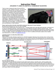
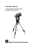
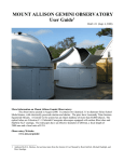
MI-250 Go-To
User Manual
September 2009 Edition
© Mountain Instruments
INTRODUCTION
This guide is provided to help familiarize
you with the various components of your
new MI250 Go-To mount. The manual is
arranged into sections.
The first four
sections cover setting up the mount,
balancing the OTA, polar alignment, and
the MI-250 Go-To Specifications.
The
Gemini instruction will be found on the
enclosed CD.
It is important that you read through this
guide and familiarize yourself with the
components that you have received.
Misuse and misunderstanding of the mount
may result in damage to the mount or to
your optical tube as well.
Component Parts of the MI-250 Go-To
RA assembly (also can be referred to as RA, Right Ascension or polar base). The
RA assembly is shipped pre-attached to the rocker base (also known as
altitude/azimuth base).
German declination assembly (also known as German dec or dec axis).
Counter weight shaft.
Counter weights and counter weight nuts.
MI8P – Pier assembly (optional). The pier assembly consists of 3 legs with
hardware.
In order to maintain proper worm to gear mesh, remove the Dec assembly
from the RA for transportation or storage. Failure to do so will reduce
tracking accuracy.
Reference Orientation
Throughout this manual there are references to the north, south, east and west of
the mount. We will assume that the mount is polar aligned. The orientation is
referenced from the face of the mount (i.e. the part with the electronics on it) which
is facing north. The smaller end of the polar assembly faces south. Thus, if you are
facing the electronics,( which puts north behind you) you are facing south. In that
position, your right hand is west and your left is east.
SECTION 1 SETTING UP THE MOUNT
1.1 Mounting the Base to the Pier
After assembling the pier, the first step in setting
up your MI-250 Go-To is to secure the RA
assembly to the pier. Begin by removing the three
bolts from the lower black anodized RA base
assembly. These are the three bolts that will
secure the base to the top of the pier. The pier has
been marked with a with a north arrow. Turn the
pier so that the arrow points north prior to
mounting the RA assembly. The picture shows the
Mountain Instruments MI-8P heavy-duty pier.
Place the mount into the top of the pier and line up the holes. Snug down the three
bolts. Do not force them to the point of stripping the threads.
1.2 Attaching the Dec Assembly
The next step is to attach the German declination assembly to the RA assembly.
The dec assembly is top heavy so before attaching the dec assembly, tighten the
RA clutch screws. See the next section for clutch adjustment.
Be sure to wipe off any debris that might be on the
face of the polar shaft or the flat surface of the dec
assembly prior to assembly. Locate the ½” center
hole on the dec assembly. This hole is provided to
register the center of the dec assembly onto the
center stud of the polar shaft. It also steadies the
dec assembly while securing the dec bolts. Do not
rely on the center stud to hold the dec in place while
fastening the dec bolts.
Place the dec assembly onto the center stud and
screw in the dec bolts. Insert each and partially
screw down all the bolts before tightening any one
bolt. Again, take care not to over-tighten any of the
bolts as this will strip the threads; tighten just enough to provide a snug fit.
After securing the dec bolts, screw the counter weight shaft into the dec assembly.
Hand tighten the shaft to the point where there is no play in it.
In order to add the counter weights to the shaft, first loosen the primary RA clutch
adjustment screws (refer to next page) and rotate the dec axis to a horizontal
position. Screw one of the weight locking nuts onto the counter weight shaft. Place
one or two counter weights onto the shaft and thread on the other locking nut. Note
that the counter weight itself is not threaded. Return the dec axis to the “counter
weight down” position. The OTA can now be attached to the saddle plate.
1.3 RA and DEC Clutch Adjustment Procedure for Both Axes
Once the OTA and counter weights are in place, the slip clutches should tightened to
the point so that there can be no
manual movement. (for go-to use)
There are two clutch levers on each
axis. Tighten both knobs on each axis
to lock clutches.
SECTION 2 BALANCING THE OTA
Whenever the mount and OTA are assembled after transportation or storage, the
system should always be balanced. Accurate tracking depends on proper balance.
2.1 RA Balance
Prior to balancing the RA or dec axis, attach any cameras, finders, oculars or guide
scopes that you plan to use during your session.
Loosen the RA clutch screws and position the OTA to either the east or west side of
the mount. Use caution during this procedure due to the system being initially
unbalanced. Then determine if the OTA or the counterweight side is heavier.
Depending on which side is heavier, adjust the counterweight up or down the shaft
as necessary to achieve balance in RA. Once balance is achieved, hand tighten the
counter weight locking nuts into place. Do not use tools for this, as it will wear the
threads on the locking nuts.
You will probably find that a slight imbalance to the east side will give the best
tracking. i.e. the east side should be slightly heavier. This will help to take up any
backlash between the gear and the worm.
2.2 DEC Balance
Tighten the RA clutch screws with the declination axis in a horizontal position.
Loosen the dec clutch knobs and position the OTA in a horizontal position. As with
the RA, be careful not to let go of the OTA. When out of balance, it will fall!
Your system was purchased with two, preinstalled female dovetail assembly (DA’s).
Slightly loosen them so that you can slide the OTA forward or back. Take care in
doing this as the OTA could slip loose and fall. Move the OTA back or forth until you
achieve balance. After achieving balance, tighten the DA’s so that the OTA can not
slide in either direction. Please note that your Losmandy male dovetail will have
been supplied with a safety thumb screw, which should be used as a safety
precaution.
You may find that you need to add a supplemental weight system when attempting
to balance some Schmidt Cassegrains. When taking photographs, this balance
process should be performed and fine-tuned for the specific area of interest in the
sky.
SECTION 3 POLAR ALIGNMENT
Described below is a simplified version of the “star drift method”. It is among the
most accurate methods known for precision polar alignment. An illuminated ocular
will be necessary. Drift alignment time can be reduced significantly by the use of a
Mountain Instruments polar alignment scope.
You will need the system running in order to polar align. Refer to Gemini manual for
proper start-up.
The adjustment of the polar axis is accomplished with the azimuth and altitude lock
down handles and knobs. It is easier
to practice with these adjustments in
the daylight so that you become
familiar with rotational directions.
3.1 Azimuth Star Drift
IMPORTANT: Keep the alt and az
handles turned in or remove the
handle(not the inner barrel) when
not in use. If not , the saddle plate
or dec assembly could hit the
handles and damage the unit.
Use the bubble level to level the pier. Assuming you have followed the previous
instructions, the mount should be oriented north. With the drive running in sidereal
mode, point the OTA to a star on the meridian at about 0 degrees declination.
Orient the cross hairs to north, south, east and west. If you have trouble orienting
yourself to N, S, E, and W, try this: whilst viewing the star in the cross hairs, gently
put a little pressure with your finger on the back top end of the tube and watch the
star try to move. This will help you orient yourself to the north/south direction. Recenter the star. Sit back and watch it drift for a few minutes. If the star drifts north,
the polar axis is too far to the west. If it drifts south, the polar axis is too far to the
east. See diagram below.
North
West
North
East
Face of mount
South
West
North
East
Face of mount
South
(1) Point the system north
West
East
Face of mount
South
(2) If star drifts north-move east
(3) If star drifts south-move west
While you are watching the drift, disregard the periodic error (east and west
movement of the star). We are only interested in the direction of the north or south
drift. Make the necessary adjustments in azimuth, re-center the star, and allow to
drift again. Repeat the procedure until there is no north or south drift.
The drift accuracy needed will be dependant upon the maximum exposure (length
of time) you intend to photograph. For example, if you intend to take a 30 minute
exposure, there should be no drift for a minimum of 30 minutes.
3.2 Altitude Star Drift
Once the azimuth drift is completed, turn the telescope to point approximately 30
degrees above the eastern horizon and about 0 degrees declination. Center the star
in the cross hair and watch the direction of drift. If the star drifts north, the polar axis
is too high and needs to be lowered. If the star drifts south, the polar axis is too low
and needs to be raised.
The first step in making the adjustment is to loosen the altitude lock down handles.
Then turn the altitude adjustment knob to effect a movement. Again, before you
make an adjustment, think it through and practice in the daytime. Remember to
retighten the lock down handles.
Go through a couple of iterations with adjusting and re-centering of the star. You
should arrive at the point where there is no drift for as long as your planned
exposure. If you care to take it a step further, go back to the azimuth and re-check
it. With a little practice, you can star drift very accurately in about 30-40 minutes.
The star drift time can be reduced to about 10 minutes using the polar alignment
scope.
SECTION 4 MI-250 Go-To SPECIFICATIONS
4.1 RA Assembly
* 7.5” RA drive-360 teeth
* Matching precision worm-1:1 ratio worm to motor shaft
* Class 7 bearings used in worm assembly
* Conical shape for maximum rigidity-cast of #319 aluminum alloy-tempered
* Major polar axis bearing-3.74” diameter-class 7
* Variable friction slip clutch
* Powder coated and black anodized finish
* Fine adjustments in altitude and azimuth
* Total base weight 36 pounds
4.2 German Declination Assembly
* 7.5” drive-360 teeth
* Matching precision worm-1:1 ratio worm to motor shaft
* Class 7 bearings used in worm assembly
* Conical shape for maximum rigidity-cast of #319 aluminum alloy-tempered
* Major dec axis bearing-3.74” diameter-class 7
* 24 pounds total
* Isolated and removable counter weight shaft
* 2 each, 20 pound counter weights
• Pre-installed LOSMANDY DA’s on saddle plate
MI-250 Worm Adjustment
Worm to gear mesh is critical to the proper operation and tracking of your MI-250.
There may times that you need to adjust your mount. By following the steps below,
proper mesh can be achieved and maintained.
Please carefully read this document completely and understand it prior to making
any adjustments.
Worm adjustment is easiest to do during daylight hours or in a well lighted
environment.
Part 1) RA Adjustment
Step 1) With only the RA axis set up on your pier, begin by removing the front cover
plate (with the MI logo) of your RA assembly. Set the cover to the side. Tighten the
clutch screws prior to adjusting the worm.
Step 2) It is best to adjust the worm to gear mesh under a full load. Less the RA
cover plate, assemble your system with counter weights and OTA. You’ll also need
to balance the system. Refer to Part 2 for declination worm adjustment.
Step 3) Loosen and remove the two socket head cap screw s (#5) that secure the
motors’ gear box to the worm bearing block.
Step 4) Carefully remove the motor, taking notice how the coupling (#6),
disassembles. Set it aside for the moment.
Step 5) Now is a good time to inspect your current mesh. Using your thumbs to
turn the worm, rotate it a few revolutions to get the “feel” of it. Are there rough
spots? Is there binding? Rock your RA axis east to west to get a feel for the current
backlash. (back lash is the movement allowed within the gear to worm mesh)
Step 6) Locate the two worm adjustment screws (#2) Back them off slightly and
then screw them in to re contact the worm assembly. Do not apply pressure. Stop
turning when you first feel contact.
Step 7) Locate the two (socket head caps screws) lock down screws (#1) With the
same Allen wrench that is used for your clutches, loosen the right side first then
gently snug it back down. Then do the same to the left side lock down screw. We
don’t want them so tight as to prevent adjustments, and at the same time we want
them secure. Important: Don’t remove both screws with the OTA and
counterweights assembled. There is a lot of pressure on the worm. It holds your
system in place. Removing the worm or its lock down screws will cause your system
to crash!
Step 8) If your mesh seemed tight, you need to loosen it. If the mesh seemed loose,
you need to tighten it. Let ‘s assume it was tight. Put the Allen wrench back into
the right side socket head cap screw (lock down screw) and leave it there. With
one hand, slightly loosen that lockdown screw and with the other hand, turn the right
side adjustment screw outwards (counter clockwise) about 1/32 of a turn. Turning
the adjustment screw 1/32” actually moves the worm by about 0.001” (one
thousandth of an inch). The point is that it doesn’t take much to make adjustments!
Step 9) With one hand, using your thumb and forefinger, apply pressure to the
bearing blocks forcing the worm assembly against the adjustment screws (#2) and
slightly re tighten the right hand lock down screw (while applying the pressure
against the adjustment screws). Move the Allen wrench to the left side lock down
screw and slightly tighten. Now move it back to the right side and tighten more.
Finish by tightening down the left hand side.
Step 10) Repeat step 5. Freewheel the worm a few revolutions. Does it feel
different than the first time? If not, repeat the steps. If you went too far, reverse the
adjustment screw direction. Don’t be surprised if it takes numerous times to get it
right. Even with a lot of practice here at Mountain Instruments, it can still take us
15-20 minutes to adjust a system properly.
There is always controversy as to how tight the mesh should be. We have found
that the best performance is achieved when there is a slight amount of backlash.
We need a small amount to allow for expansion and contraction of the system due
to temperature variations. As such, it is ideal to adjust the system at the
temperature that is near your normal using temperature however, that is not always
possible to do.
Step 11) Re install your motor assembly and replace the cover plate.
Part 2) Dec Adjustment
The actual adjustment procedure for the declination axis is the same as that for the
RA. The difference is in accessing the dec worm gear.
Step 1) In order to access the dec axis worm assembly, remove the OTA and the
counterweights. Make sure that the RA clutch screws are secure otherwise the dec
can fall to one side or the other. Completely remove the clutch knobs. Close
inspection of the saddle plate will reveal a set of four socket head caps screws in
the middle of the plate. These screws secure the saddle plate to the top of the dec
axis. You will need to carefully remove the screws and lift off the plate. Set it aside.
Step 2) Remove the cover plate for complete access to the worm and gear
assembly. Replace the clutch knobs before making adjustments.
Step 3) Make adjustments as previously described.
There are two methods you can use. The first method is to make your adjustments
to the dec axis without the OTA and counter weights in place. This is the easiest
however less precise method.
The second is to make adjustments with the OTA and Counter weights in place.
Remove the cover plate and then reattach the saddle plate and re install the counter
weights and OTA. Adjustment can then be made under a load. If you choose this
method, be sure to properly balance the OTA prior to adjusting the worm and gear
mesh.
MI-250 Worm replacement
Part 3
If the worm assembly of either the RA or dec axis has been removed, the following
procedure should be used for replacing it in the proper position prior to making final
adjustments as described in Step 1 through Step 10.
Important: The worm assembly can only be removed when the OTA,
counterweights, and declination assembly have been removed from the RA
assembly.
The adjustment procedure is simplified by the use of a piece of “key stock”
available from most hardware stores. It is important that the key stock be .25” by
.25” square (1/4” x 1/4”) and about 1” long.
When placing the worm assembly back into the mount, the angular position of the
worm axis needs to be tangential with an imaginary gear center line. (see diagram).
By virtue of the MI-250 design (manual and go-to models) the worm has an offset.
Look closely at the diagram. You will see that the left side (“A”) of the worm (from
the left of the worm teeth to the bearing) is longer than it’s counter part on the right
side of the teeth (“B”) . As such, the gear is not being driven by the center of the
worm teeth. In fact the “driving teeth” are a couple of teeth to the left side of the
center line of the teeth section.
Center line of gear
Key Stock .25 x.25
Gear
offest from center
"A"
"B"
When replacing the worm assembly, first insure that any brass shims that may have
been originally used under the worm assembly, are replaced back to the same side
that they came from. This is important because the may vary in thickness. These
shims precisely position the center line of the gear to the center line of the worm as
viewed from a horizontal position. In other words, the shims “lift” the worm to the
exact horizontal center line position.
Back out the worm adjustment screws. This allows for easier reinstallation of the
worm assembly.
Once the worm assembly is in place and the lock down screws are in place to finger
tightness rough adjustments can be made with the key stock. From a vertical
position, insert the key stock flush against the bearing with it’s right upper corner
just touching the actual gear. See diagram. You may have to tip-tilt the worm
assembly to achieve this rough position. Do this by adjusting the worm adjustment
screws.
This method will get you into the ball park with regards to the tip-tilt angular position
of the worm to gear. Ideally, after the final adjustments are completed, the key
stock will just barely fit into place. You can now proceed with steps 1 through steps
10 for final adjustments.
Worm lateral adjustment
Your worm assembly consists of two bearing blocks and one cross piece. The
larger bearing block accommodates the motor assembly. The opposite end is
smaller in size.
The smaller bearing block has been modified so that any lateral play of the worm,
between the two bearings, can be adjusted out. Look at the outside end of the
small bearing block. You’ll see three very small set screws at 120 degrees apart,
that are around the outside bearing race. These set screws are 1/8” long, 6-32’s.
With an Allen wrench, carefully snug the set screws down equally, until there is no
lateral play of the worm. If you feel roughness while rotating the worm, slightly back
off the set screws.
Removal of main gear
The main gear can be removed from either the RA or declination axis for cleaning or
re lubricating. When re lubricating a gear, keep in mind that the same type of
lubrication should be used. Mixing of different lubes can result in poor performance
of lubrication. Mixing can occur if there is residual lubrication left on the worm or
elsewhere.
1) Remove dec assembly
2) Remove clutch levers (pictures
show star knobs- levers are
currently used)
3) Remove cover plate
4) Back off worm adjustment
screws
5) Loosen worm lock down screws
6) Drop down worm so that it clears the gear (not shown in picture)
7) Remove inner 4 socket head cap
screws
8) Do not let plate fall off. Set aside
9) Carefully lift out gear
10) Perform necessary maintenance
and reverse order for
reassembly.
11) Refer to worm adjustment
section to reset worm.
Adapter Plate Supplement
Your MI-250 is being mounted on your own pier or tripod via the black adapter plate
attached to the bottom of the female rocker base. To accomplish this, you’ll need to
disassemble the female rocker base from the black adapter plate in order to secure
the adapter plate to your permanent pier.
The sequence for securing your mount to your adapter plate is:
(1) Removing RA assembly from the female rocker assembly.
(2) Partial Disassembly of the Female Rocker.
(3) Removing the Female Rocker from the Adapter Plate.
(4) Re-assembling the female rocker and RA.
(5) Securing adapter plate to your pier top.
(1) Removing RA Assembly from Female Rocker Assembly (Figure 1)
The first step in setting up your MI250 is to remove the RA from the
female (bottom) rocker assembly.
Begin by removing the altitude lock
down hex head nuts. Be careful
doing this. The entire RA assembly is
secured by the altitude lock down
nuts. There is one nut on a post on
each side of the RA. After removing
the two nuts, simply lift off the RA
and set it aside for the moment.
(2) Partial Disassembly of the
Female Rocker
With the RA removed from the
female rocker, look at the altitude
adjustment. Examination reveals how this simple mechanical device works.
Turning the altitude adjustment knob advances or declines the lead screw altitude
“U-nut”.
The center pivot shoulder screw (under the U-nut) needs to be removed in order to
remove the black adapter plate. It needs to be re inserted into the center hole of the
female rocker when re assembling. To accomplish this, the lead screw will need to
be moved out of the way. Using an Allen wrench, loosen the shaft collar set screw
and loosen the locking nut. Turn the lead screw handle until you have free access
to the center hole. It will be necessary to completely remove the “U” nut in order to
access the center pivot shoulder bolt. The small Allen wrench has been provided to
loosen the shaft collar.
(3) Removing the Female Rocker from the Adapter Plate
Next, remove the female rocker base from the black adapter plate by removing the
ratchet handles. To do this, lift up on the handle and turn just to break loose. Then
remove the top center
socket head screw in the
handle. It will come out
with a spring. Now lift off
the handle. You can then
unscrew the inner part of
the ratchet. The female
rocker will then lift off the
adapter plate
You can now secure the
adapter plate to your
pier. Be sure to orient the
slotted hole to the north.
(4) Reassembling the RA and Female Rocker
Place the rocker on top of the adapter plate.. Make sure the azimuth “bar” fits into
the slotted hole on the top side of the adapter plate. Very slightly tighten the
shoulder bolt using an Allen wrench. Take care not to over tighten the shoulder
bolt. Just bring it into contact and stop. If you over tighten the shoulder bolt
you will not be able to turn the azimuth knob during polar alignment. The
shoulder bolt should be in contact and yet still allow the rocker assembly to rotate
with just a slight amount of drag.
Now re-secure the altitude lead screw assembly in the reverse order that you
removed it. Do not over tighten the collar to the point that the knob is difficult to turn.
A little backlash will not affect anything.
An additional pair of ratchets has been sent so that you can use them for the
altitude lock downs. A few drops of 3-In-One oil on the handles will help prevent
corrosion. (Your mount was sent using only nuts and washers for the altitude lock
downs)
The next step is to secure the azimuth lock-down ratchet knobs. These knobs also
secure the rocker to the adapter plate. To use, just loosen the ratchets and turn the
azimuth knob for polar alignment adjustments. To loosen the ratchets, lift the handle
and turn it to the desired position. Drop it down to engage the ratchet.
(5) Securing Adapter Plate to your Pier Top
The adapter plate needs to be secured it to your pier or tripod by whatever means
necessary, as long as it is good and secure! Make sure that any bolt heads are
under the top surface of the plate. Also, be sure to orient the slotted hole in the
adapter plate to your north position. You should try to get within a few degrees of
pointing north.
Helpful Suggestion: Drill and counter bore three holes for use with a 5/16”-18 socket
head cap screw. Counter bore half way through the plate. This is much easier than
a hex head bolt.
2
Washer Geometry
Take a close look at a stainless steel washer. You will see that on one side of the
washer, the edges are beveled or rounded. On the other side of the washer the
edges are square and sharp.
When using stainless steel washers on powder coated surfaces (which most of the
MI-250 is) place the beveled side of the washer against the powder coating. It will
help prevent scratching the paint.
3
For easier installation or removal
1)
2)
3)
4)
Remove top center Allen screw
Remove barrel and spring from handle
Screw barrel onto post
Replace spring and screw with handle
4