1
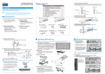
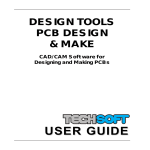
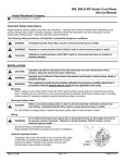
License Overview.
For detailed license agreements see the license document.
A single user license may be used on a single computer. It may not be installed on
multiple computers or a network.
A site license enables an institution to install the software on an unlimited number of
machines (and/or network) at a single physical address (i.e. buildings at a single
postcode).
In addition, educational site license holders may also purchase special student license
CDROMs (in multiple packs) to enable students or teachers of the registered
educational institution to install the software on their home computers (for noncommercial use). All other users must purchase a single user license.
Note that the software is not freeware or shareware and may not be distributed to third
parties or made available on Internet web sites or bulletin boards.
TechCAD User Manual (preliminary) © Revolution Education Ltd 2001. All rights reserved.
Page 1
TechCAD User Manual
Introduction – Graphic Drawing Packages
All computerised drawings can be divided into two ‘families’ – bitmap drawings and
vector drawings.
Bitmap drawings consist of rows of ‘dots’. This type of drawing is commonly used for
‘artwork’ such as adverts, pictures and photographs. Bitmap drawings can be output via
printers because printers also ‘draw’ rows of dots. However bitmap drawings cannot be
output on plotting devices (XY plotters and CNC engravers/millers) because these
devices can only move in ‘lines’.
Vector drawings consist of images made up from ‘lines’. This type of drawing is often
used for technical drawings and high precision CAD work. Vector drawings can be
output from a plotter, and can also be output on a printer because the printer
automatically converts the ‘lines’ into ‘rows of dots’.
TechCAD is a vector based drawing package, and so can be used to create drawings
that can be plotted, engraved or milled with a plotting device. If desired the drawing can
also be printed, and the printed image can also contain extra information such as
dimension lines and textual labels.
Output Devices Supported
Printers
All printers that operate under the Windows operating system.
Plotters
Note that throughout this document the term ‘plotter’ refers to all types of these devices.
TEP CNC Machine
XY plotters
Roland CAMM 1, 2, 3 machines
Many other CNC millers and engravers.
TechCAD User Manual (preliminary) © Revolution Education Ltd 2001. All rights reserved.
Page 2
Step by Step guide to setting up the TEP CNC Machine
1. Install the software from the CDROM.
2. Connect the serial cable to the computer serial port. (Note which connection
COM1 (or ‘A’) or COM2 (or ‘B’) is used). If the computer has an older style 25 pin
serial connector on COM2 it will be necessary to purchase a 9-25 way ‘mouse’
adapter from any high street computer store.
3. Connect the other end of the serial cable to the CNC serial interface.
4. Connect the ribbon cable from the CNC serial interface to the CNC Machine.
5. Connect the power supply to the CNC Machine.
6. Make sure the safety cover is down to disable the safety cut-off switch.
7. Use the serial interface keypad to move the tool to the bottom left-hand corner of
the milling bed. Press the ‘datum’ switch to set the datum (0,0) position.
8. Start the TechCAD software. As a first test drawing, use the rectangle tool to
draw a small rectangle approx 10mm x10mm in the bottom left hand corner of
the drawing area (defined by the green dotted line).
9. Select ‘Plotter Setup’ from the File menu. Make sure that the plotter type is set to
‘TEP CNC Machine’ and use the ‘Ports’ button to select the correct serial port.
Click OK to save the settings and return to the main drawing.
10. Select ‘Plot’ from the File menu. Click ’Plot’ to accept the default values. When
the plot preview appears click ‘Plot’ to start the plot.
11. If the serial port is selected correctly the plot will then start – a progress bar is
displayed on-screen to show how much of the plot has been completed. If an
error message is displayed check that the cable is connected correctly and that
the correct serial port is connected.
12. To cancel a plot click the ‘Cancel’ button beside the progress-bar. Note that the
cancel will only take place after the current action is completed. The CNC
machine will automatically return to the datum position after the cancel.
In the case of an emergency press the ‘stop’ button on the serial interface.
After an emergency stop it is necessary to cancel the plot within the
software, and then to also press the ‘reset’ button (and then reset the
datum) on the serial interface before starting a new plot.
TechCAD User Manual (preliminary) © Revolution Education Ltd 2001. All rights reserved.
Page 3
The TechCAD Software
The software has a main drawing area as shown below:
Also displayed are four bars:
Toolbar
This contains shortcut buttons for various menu options.
Toolbox
This toolbox is used to select the various mouse drawing tools.
Co-ordinate bar
The co-ordinate bar displays the current absolute and relative positions of the mouse
pointer. When drawing certain shapes the distance and angle moved will also be
displayed.
Status bar
The status bar displays information about selected shapes and other general
information.
TechCAD User Manual (preliminary) © Revolution Education Ltd 2001. All rights reserved.
Page 4
Understanding the Drawing Area
The drawing area is defined by the area specified by the Setup>Page Setup menu.
The drawing area uses a Cartesian grid reference system, where the origin (point 0,0) is
at the bottom left corner of the page, the X-axis is along the bottom of the page and the
Y-axis is up the lefthand side of the page.
The full drawing area is displayed when a new drawing is opened, but it is possible to
zoom in to a smaller area using the zoom mouse tool (or the View>Zoom menus). When
using the zoom mouse tool, the zoom will be applied to the area defined by the
rectangle drawn with the mouse tool. To ‘unzoom’ out to the full screen view right-click
the mouse.
To move around the drawing area use the pan mouse tool. Select the pan mouse tool
and then click and drag the mouse to move the active window.
Note that it is possible to draw outside the page area, which is defined with a dotted
green border. Shapes that are drawn outside this area will be saved, but will not be
printed or plotted. This area can therefore be used for temporarily storing shapes when
constructing complex drawings.
Layers
Layers are used to separate the drawing into several parts, so that, for instance, each
layer can be plotted or printed separately. New shapes are always drawn on the active
layer, which is selected from the Active Layer list on the toolbar.
Layers can be renamed and edited by clicking on the layer properties toolbar button. If
desired all shapes on a layer can be hidden from view or locked so that they cannot be
accidentally moved or resized.
To add or delete new layers use the Setup>Layers menu.
TechCAD User Manual (preliminary) © Revolution Education Ltd 2001. All rights reserved.
Page 5
Grid
The drawing area can display a grid (View>Grid menu or Grid toolbar button) to assist
with precision drawing. The size of the grid can be altered using the Setup>Grid Setup
menu.
Shapes points will automatically snap to the grid points when ‘Snap To Grid’ is enabled
(View>Snap to Grid or Snap to Grid toolbar button).
When orthogonal lock is enabled (View>Orthogonal Lock menu or Orthogonal Lock
toolbar button) shape points can only be added vertically or horizontally in straight lines.
Selecting Shapes
A shape is selected when it’s point handles (black squares) are displayed. When a
shape is selected it’s properties can be altered by clicking on the ‘Shape Properties’
toolbox button (or using the Edit>Properties menu).
To select a single shape use the ‘Select’ tool to click on the shape. To select multiple
shapes hold down the shift keyboard key whilst clicking on the shapes.
To select all shapes in a certain area use the ‘Net Select’ tool to draw a selection
rectangle around the shapes.
TechCAD User Manual (preliminary) © Revolution Education Ltd 2001. All rights reserved.
Page 6
Drawing Shapes
There are two main types of shape – line shapes and filled shapes.
Line shapes include lines, arcs, freehand and splines. A line shape is drawn with a type
of line that is defined by the ‘pen’ properties. The pen width, colour and lstyle can be set
independently for each shape.
Filled shapes include rectangles, polygons, circles, ellipses and closed splines. The
outer boundary of a filled shape is defined by the ‘pen’ properties. In addition, the ‘fill’ of
the shape can be defined by the ‘brush’ properties. These brush properties define the
style of the fill (none, full, hatch), background and foreground colours, and whether the
shape is transparent or opaque.
New shapes are always drawn on the current layer using the layer default settings.
Therefore to change the appearance of all new shapes drawn on a particular layer,
change the default layer properties.
New shapes are always drawn ‘on top’ of other shapes. The position of shapes can then
be altered using View>Arrange menu or the ‘Bring to Front’ or ‘Send to Back’ toolbar
buttons.
TechCAD User Manual (preliminary) © Revolution Education Ltd 2001. All rights reserved.
Page 7
All shapes are defined by ‘points’, which are indicated with handles (black squares)
when the shape is highlighted. The position of each point can be moved with the
mouse, or precisely edited from within the shape properties. Individual points can also
be added or deleted by right-clicking the mouse over the handle when the shape is
highlighted.
Shapes can be drawn by clicking on the appropriate toolbox button to select the desired
shape type. Then move the mouse into the drawing area and left-click to start drawing
the shape. Subsequent points can then be added by moving the mouse and left-clicking
again. To end polyshapes (shapes with multiple corners) it is necessary to double-click
at the desired end point.
All shapes can be printed and plotted. However filled shapes may be automatically
converted to ‘outlines’ for plotting (dependant on plotter type).
TechCAD User Manual (preliminary) © Revolution Education Ltd 2001. All rights reserved.
Page 8
Shape Types
Line
A line is a straight line between two points. To draw a line select the line mouse tool and
then left click to start the line and then left click to end the line.
Polyline
A polyline is a number of straight lines between points. To draw a polyline select the
polyline mouse tool, left click to start, left click to add more points, and then double click
to end.
Rectangle
A rectangle is drawn between the bottom left and top right corners. To draw a rectangle
select the rectangle mouse tool, left click to define the bottom left ‘corner’ start and then
left click to define the top right ‘corner’.
Polygon
A polygon is a closed shape that can contain any number of corners. To draw a polygon
select the polygon mouse tool, left click to start, then left click to add more corners, and
then double click to end.
Freehand
Freehand is an alternative way of drawing polylines. The freehand line follows the
mouse as it is moved, rapidly adding points as the mouse moves. Although a versatile
drawing method, the freehand tool should be used with care if the finished shape is to
be plotted, as a large number of points can be created. To draw a freehand line select
the freehand mouse tool and then left click and drag the mouse.
Circle
A circle is drawn by defining the centre point and the radius of the circle. To draw a
circle select the circle mouse tool, left click to define the circle centre point and then left
click to define the radius.
TechCAD User Manual (preliminary) © Revolution Education Ltd 2001. All rights reserved.
Page 9
Ellipse
An ellipse is drawn between the bottom left and top right corners of an ‘imaginary’
rectangle that would surround the ellipse. To draw an ellipse select the ellipse mouse
tool, left click to define the bottom left ‘corner’ start and then left click to define the top
right ‘corner’.
Arc (also see 3 Point Arc)
An arc is drawn by defining a centre point and then the start and finish angle of the arc.
To draw an arc select the arc mouse tool, left click to set the centre point, double click to
set first end point and then double click to set the end point.
3 Point Arc (also see Arc)
A 3 Point Arc is drawn by defining a start, centre and end point. To draw a 3 Point Arc
select the 3 Point Arc mouse tool, left click to set the start point, left click to set the
centre point and then left click to set the end point.
Spline
A spline is a curve that joins multiple points together. To draw a spline select the spline
mouse tool, left click to start, left click to add new points, and then double click to end.
Closed Spline
A closed spline is a closed curved shape that passes through a number of defined
points. To draw a closed spline select the closed spline mouse tool, left click to start, left
click to add new points and then double click to end.
Groups
Shapes can be grouped together, so that they can be easily moved or copied as a
single unit. To group shapes together simply highlight the desired shapes and then click
on the ‘Group’ toolbar button.
To separate a group back into individual items click on the ‘Ungroup’ toolbar button.
TechCAD User Manual (preliminary) © Revolution Education Ltd 2001. All rights reserved.
Page 10
Other Drawing Tools
Dimension Lines
Dimension lines can be drawn using single or double arrow ended lines. Use labels to
add information (e.g. ‘10’) to the dimension line. Dimension line can be printed but are
not plotted.
Text and Labels
Labels are used to add textual information to the drawing. Labels can be set to any
colour, true-type font or angle by changing the font properties (via the Shape Properties
dropdown menu on the toolbox). Labels can be printed but are not plotted.
Text is a special predefined stick font used for ‘plotting’ text on plotters. Not all plotters
support stick fonts, and the font plotted may differ in appearance to the font displayed
on screen. The size and angle of the text can be altered by changing the font properties.
Text is only included within a plot if the plotter supports stick fonts.
The textual information within text and labels can currently only be placed on a single
line. To use multiple lines use multiple shapes.
Pictures
Bitmap pictures can be added to the drawing via a picture box. This is often used so
that a particular picture can be ‘traced’ by drawing lines over the picture before deleting
the picture. Pictures can be printed but are not plotted.
TechCAD User Manual (preliminary) © Revolution Education Ltd 2001. All rights reserved.
Page 11
Shape Transformations
When creating complex drawings it is often useful to be able to transform shapes, e.g.
to reflect or rotate a shape. The following transformations are available from the
Edit>Transform menu (note that not all transformations are available for all shape
types).
Reflect
This transformation reflects the shape either vertically or horizontally (or both).
Rotate
This transformation rotates a shape anti-clockwise by the selected angle.
Scale
This transformation scales the shape from a fixed reference point. Select a scale factor
less than 1 to reduce the shape size.
Shift
This transformation moves the shape a fixed X and/or Y distance
Shear
This transformation scales each point a fixed distance from the origin (0,0).
Rapid Copy and Cut/Copy/Paste
To rapid copy a shape simply hold down the ‘Ctrl’ keyboard key whilst selecting a
shape. A duplicate identical shape will then be created which can then be moved to the
new location.
The standard Edit>Cut/Copy/Paste menu (or toolbar shortcut buttons) can also be used
to duplicate shapes or groups.
To copy the whole drawing for pasting into another application (e.g. Microsoft Word) use
the File>Export To Clipboard menu.
TechCAD User Manual (preliminary) © Revolution Education Ltd 2001. All rights reserved.
Page 12
Saving Files
Files are automatically saved in the default CAD format. This is a custom format not
available in other applications. To enable the drawing to be used in other applications it
is necessary to export, rather than save, the file.
Exporting
The drawing can be exported in various graphic formats for use with other applications,
such as for use in presentations or publishing on the Internet. The following file formats
are available from the File>Export menu.
DXF (Data Exchange Format)
A vector based format used to exchange graphic files between different applications.
Recommended when opening the drawing in other drawing applications.
GIF (Graphics Interchange Format)
A compressed bitmap format, normally used for publishing drawings on the Internet.
EMF (Enhanced Metafile Format)
A vector based format used within Windows applications. Recommended for use in
presentations and reports.
BMP (Bitmap Format)
A bitmap format used within Windows applications.
Importing
The software can import data exchange format (DXF) files (release 12) saved from
other applications. Note that the software does not support all possible DXF commands
and so some files may not be fully imported into the software (if the file contains
commands not supported by TechCAD).
TechCAD User Manual (preliminary) © Revolution Education Ltd 2001. All rights reserved.
Page 13
Toolbar Buttons
New – start a new drawing
Open – open an existing drawing file
Save – save the current drawing to file
Cut – copy the shape to the clipboard and remove original
Copy – copy the shape to the clipboard, leaving the original
Paste – paste the shape from the clipboard to the active layer
Delete – remove the selected shapes from the drawing
Undo – undo the last action
Bring To Front – bring the selected shape to the top
Send to Back – send the selected shape to the bottom
Group – group the selected shapes together
Ungroup – ungroup the selected group
Grid – display/hide the grid
Snap To Grid – enable/disable the snap to grid function
Orthogonal Lock – enable/disable the orthogonal lock function
Active Layer – select the current drawing layer
Layer Properties – edit the active layer properties
TechCAD User Manual (preliminary) © Revolution Education Ltd 2001. All rights reserved.
Page 14
Toolbox Buttons
Select – use to select shapes so the shape can be edited/moved etc.
Net Select – use to rapidly select all shapes in an area
Pan – use to move around the drawing area
Zoom – use to zoom in on an area. Right click to unzoom.
Line – left click to start, left click to end
Polyline – left click to start, left click to add point, double click to end
Rectangle – left click to start, left click to end
Polygon – left click to start, left click to add point, double click to end
Freehand – hold down left click whilst drawing
Circle – left click to start, left click to end
Ellipse – left click to start, left click to end
Arc – left click to set centre, double click to set first end, double click to end
3 Point Arc – left click to start, left click to set centre, left click to end
Spline – left click to start, left click to add point, double click to end
Closed Spline – left click to start, left click to add point, double click to end
Text – left click to set text position, then enter text
Picture – left click to start, left click to end, then enter filename
Dimension – left click to start, left click to end
Label – left click to set text position, then enter text
Shape Properties – edit the selected shape properties
Shape Properties Dropdown Menu – edit the additional shape properties
TechCAD User Manual (preliminary) © Revolution Education Ltd 2001. All rights reserved.
Page 15
Printing
Printing allows all elements of the drawing to be output via any printer that is supported
by the Windows operating system. Note that printing is normally used to produce a
scaled output. For a precision output a plotter should be used.
To select the correct printer select the File>Print Setup menu
To print the drawing select the File>Print menu.
It is then possible to select which layers are to be printed, and to optionally hide some
parts of the drawing (e.g. dimension lines). Once the selections are made click ‘OK’ to
view the print preview and then start the print.
Plotting
Plotting allows all plottable elements of the drawing to be output to a XY plotter or CNC
machine. Elements of the drawing that cannot be plotted include labels, dimension lines
and pictures. All filled shapes may be also converted to outlines before plotting
(dependant on plotter type).
To select the correct plotter select the File>Plot Setup menu. Make sure the correct
serial port is selected (normally COM1 or COM2) by clicking on the ‘Ports’ button.
To print the drawing select the File>Plot menu.
It is then possible to select which layers are to be plotted. It is also possible to configure
the plotter (e.g. cutting speed) by clicking on the ‘Setup’ button. Once the selections are
made click ‘OK’ to view the plot preview and then start the plot.
Plotting is normally carried out by custom drivers that communicate with plotter via the
serial port of the computer. These drivers are constantly being updated to support new
machines, and all new drivers can be downloaded from the TechCAD website at
www.rev-ed.co.uk. After downloading a new driver use the Setup>Driver Import menu to
add the new driver to the software.
Whilst a plot is in progress a ‘progress bar’ will display the percentage of the plot
completed. This progress bar will always lie on the top of the desktop, but can be
moved by dragging the window. It is possible to modify a drawing whilst a plot is in
progress, but only one plot can be carried out a time. Therefore the ‘plot’ menu will be
disabled until the first plot is complete (or cancelled).
TechCAD User Manual (preliminary) © Revolution Education Ltd 2001. All rights reserved.
Page 16
Configuring your Printers and Plotter
Most users will normally wish to output to both printers and plotters. For this reason it is
recommended to connect the printer to the computers printer port and the plotter to the
computers serial port, so that no ‘cable-swapping’ is required to use both devices. The
software also supports network printers.
Connecting the plotter to the serial port has several advantages. TechCAD contains
custom drivers that allow precision control of the plotter via the serial port, making it
much easier, for instance, to cancel plots if necessary. All computers are supplied with
both a serial port and a printer port, so that it is natural to connect two devices
simultaneously to the two different ports. Most other Windows application also ‘expect’ a
printer (rather than a plotter) to be connected to the printer port.
Most plotters are fitted with both serial and printer port. If you require a serial cable for
your plotter this can be purchased from www.rev-ed.co.uk. Note that as serial cable
configuration can vary it is not recommended to use serial cables from other devices
(e.g. a modem).
Some low cost or older plotters (e.g. Roland Modela) are only fitted with a printer port.
In this case it is necessary to install a ‘Generic Printer Driver’ under the Windows
operating system and connect the plotter to the printer port. Further details on how to do
this are provided within the help file.
TechCAD User Manual (preliminary) © Revolution Education Ltd 2001. All rights reserved.
Page 17