1
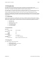
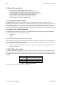
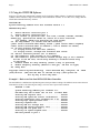
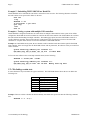
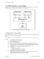
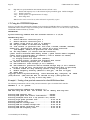
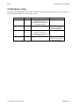
USBtest 2000
User’s Manual
M200038-04
July 2000
Preliminary
Sycard Technology
1180-F Miraloma Way
Sunnyvale, CA 94085
(408) 749-0130
(408) 749-1323 fax
http://www.sycard.com
USBtest 2000 User’s Manual
Page 1
1.0 Introduction
The USBtest 2000 Universal Serial Bus (USB) port tester is designed to provide manufacturers of USB
based hosts a quick method of testing and verifying the operation of the ports. Sycard’s USB port tester supports the
USB 1.0 and 1.1 specification. The USBtest 2000 is also capable of testing external hubs.
The USBtest 2000 is a self-contained unit containing two independent USB devices. Test software resides on both the
host PC and USBtest unit. Simple command line invocation allows tests to be embedded into batch test files.
Software included with the USBtest unit supports a wide variety of host controller implementation based on the
Universal Host Controller (UHCI) architecture or the Open Host Controller Interface (OHCI). For other host controller
architectures, Sycard Technology can provide technical documentation describing how to create custom test programs
for the USBtest.
1.1 Compatibility
USBtest has been designed to be compatible with a wide variety of USB host controllers. Both Open Host Controller
Interface (OHCI) and Universal Host Controller Interface (UHCI) hosts are supported. Host test software is compatible
with most PC compatible machines. The current software has been tested with the following USB host controllers
•
•
•
•
•
•
Intel PIIX4 UHCI
Intel PIIX3 UHCI
Opti FireLink 82C861 OHCI
CMD USB0670 OHCI
Via VT82C586B UHCI
Cyrix CX5520 OHCI
1.2 Specifications
Electrical
Supply Voltage
Physical
Height
Length
Width
Environmental
Temperature
Humidity
Reliability
Connector Life
9VDC @ 400mA
1.5”
6.5”
6.0”
0 - 50 degrees C
0 - 95 % Non condensing
Rated at 10,000 insertion/removal cycles
1.3 Packing List
The USBtest package includes the following:
•
•
•
•
M200038-04
USBtest 2000 Test Unit
USB A-B 20/28 Gauge 1 meter cables (2)
USBtest Software Diskette
USBtest User’s Manual
©1994-2000 Sycard Technology
Page 2
USBtest 2000 User’s Manual
1.4 Related Documentation
Universal Serial Bus Specification - Revision 1.0 and 1.1
Open Host Controller Interface Specification for USB - Release 1.0a
Universal Host Controller Interface (UHCI) Design Guide - Revision 1.1
Intel 82371AB PCI-to-ISA / IDE Xcelerator (PIIX4) Data Sheet - April 1997
Intel 82371SB PCI-to-ISA / IDE Xcelerator (PIIX3) Data Sheet
Intel 8x930Ax Universal Serial Bus Microcontroller Data Sheet
Universal Serial Bus Architecture - Mindshare, Inc.
1.5 Installing the USBtest Software
The USBtest software consists of two executable programs. TESTUSB.EXE is designed to test USB root hubs.
TESTHUB.EXE is designed for external hubs,. To install the software, simply copy the executables to your hard disk. If
desired, the programs may also be executed directly from the floppy disk. Also included on the diskette is a READ.ME
file containing information on any recent changes in the software. Software updates may be downloaded from the
Sycard Technology WEB page at http://www.sycard.com. Technical support may be addressed to [email protected].
1.6 Setting Up the USBtest Hardware
The USBtest 2000 is powered through a plug-in wall mount transformer. The transformer supplied with the USBtest
unit has been approved for use in the following countries:
United States
Canada
Taiwan
Contact Sycard Technology for transformers for other countries.
Once the USBtest unit is properly powered the power LED on the front panel will light. On power-up the status LED on
each port will momentarily light and then go off. If the LED stays on after initial power-up or reset, this indicates that
the port has failed its self-test and must be repaired.
Note: Use only the supplied USBtest cables. Longer cables or cables with smaller wire gauge may affect the
voltage measurements.
1.7 The USBtest Front Panel
The USBtest 2000 front panel provides two USB ports labeled Port 0 and Port 1. Both ports are fully independent and
can be connected in any order. Both ports may be connected to a dual port host or the two ports can be shared between
two single port hosts. Each port has a Status indicator associated with it. The status indicator will provide the following
functions:
Operation
Status Indicator
Power-on
Momentarily light and then go off.
Ready to Test
Off
Testing
Blinking
Port Failure
Steady on
Table 1.7-1 Status Indicator States
The Power Indicator will light whenever power is applied.
©1994-2000 Sycard Technology
M200038-04
USBtest 2000 User’s Manual
Page 3
2.0. USBtest Operation - Root Hubs
The USBtest 2000 is a self-contained dual port test peripheral. The diagram in Figure 2.0-1 illustrates the major
functional blocks of one of the test peripherals. The Intel 80C930 USB microprocessor controls the operation of the
system. All communications with the test peripheral occur through the USB interface. Test status is communicated
through the USB interface and a single status LED.
Power
Supply
DC
Power
Jack
System Vcc
Reset Switch
Term
Control
USB
Conn
D+
D+
D-
D-
Status LED
USB
Microcontroller
Term
Control
Vcc
GND
Vcc
EPROM
GND
Load
Shield
D+
D-
Mux
A/D
12MHz
Figure 2.0-1 USBtest 2000 Block Diagram
Note: The USBtest 2000 may be reset to its power-on default by cycling power or pressing the RESET switch
located on the back panel.
The procedure for testing the desired USB port is straightforward. Connect the USBtest to the USB port under test with
one of the supplied USB A-B cables. Both ports on the USBtest are identical. Figure 2.0-2 illustrates the connection
between the USBtest and a dual port host system. The TESTUSB test program will execute a variety of tests
automatically and return PASS or FAIL status. If any errors are detected, they will be displayed on the screen.
M200038-04
©1994-2000 Sycard Technology
Page 4
USBtest 2000 User’s Manual
USBtest 2000
Port 0
Port 1
USB 1
USB 2
System Under
Test
Figure 2.0-2 Testing a two port USB host
Figure 2.0-3 shows the connection between the USBtest and two single port USB systems. The TESTUSB software is
run on each individual system. Because the USBtest ports are completely independent, tests may be run concurrently on
each system under test.
USBtest 2000
Port 0
Port 1
USB 1
USB 1
System Under
Test A
System Under
Test B
Figure 2.0-3 Testing two single port USB hosts
Note: The TESTUSB or TESTHUB software will not operate correctly with Windows 95 in a DOS window.
Run these programs under a safe mode DOS. In Windows 95 select a “safe mode” DOS environment by
pressing <F8> during bouts.
Note: The TESTUSB software is not designed to run with a hub device connected between the USBtest and the
host root hub. See chapter 3 for instructions on the TESTHUB software to test external hubs.
©1994-2000 Sycard Technology
M200038-04
USBtest 2000 User’s Manual
Page 5
2.1 USBtest Software - Root Hubs
The TESTUSB software is an MS-DOS application distributed on a single floppy diskette. Included on the diskette is
the test application program, and a READ.ME file containing information not contained in this document. The
TESTUSB program has the following run time switches:
Syntax
TESTUSB -0 -1 -bxxxx,yyyy -cx –sx -tx -vx –lx –dx -x -f -e:x,y.. –m$
Switches
-0
Test port 0
-1
Test port 1
-0 -1
Test both ports
-bxxxx,yyyy
Select specific USB device by PCI Vendor ID (xxxx) and Device ID (yyyy)
-sx
Specify (x+1) instance of USB controller. (-s1 selects second USB host controller specified by the -b
option, -s2 select the third, etc)
-cx
Enable USB Vcc load. –c1 selects 100mA load, -c2 selects 500mA load, -c3 selects 600mA load
-sx
Select USB controller. -s2 selects the 2nd occurrence of the selected (-bxx) chip.
-tx
USB Voltage measurement tolerance in percentage (default = 10%)
-vx
Verbose level.
-v0 = Display only pass/fail status
-v1 = Display pass fail status for each individual test.
-v2 = Display actual measured values from A/D tests
-lx
USB Loaded Vcc lower Voltage (4.15 is default)
-dx
USB loaded Vcc protection device minimum Voltage drop. 0.06 is default for 500mA or 600mA
load, 100mA drop checking is disabled unless drop is specified.
-x
Disable loaded Vcc drop checking (unless a drop is specified)
-fn
Enable SOF frequency test, n is the tolerance in parts per million (ppm). Default is 800ppm.
-hx
High and Low speed termination measurement tolerance (default = 50%)
-e:x,y,.. Disable certain tests
-m$
Enter debug menu
Note: Switches can be entered in any order and must be separated by a space.
Note: To test both ports in a two port system enter -0 -1
2.1.1 USBtest Host Software Environment
The USBtest software is designed to run under DOS 3.0 or higher. During the test. USBtest software makes direct I/O
and memory accesses to the USB host controller resources. Any software or operating system that blocks or allocates
resources that conflicts with the USBtest software will cause the test to fail. See section 3.1 for information on the
resources used by the USBtest software. In Windows 95/98 the USBtest software should be run in a MSDOS Safe
mode. This assures that sufficient upper memory areas are available for the test windows. Operation in a “DOS Box”
under windows is not recommended. To enable a Safe mode MSDOS environment, reboot the computer and enter <F8>
as the computer starts to boot. A user can select a MSDOS Safe Mode from the startup menu.
M200038-04
©1994-2000 Sycard Technology
Page 6
USBtest 2000 User’s Manual
2.2 Using the TESTUSB Software
Section 2.1 describes the command line switches used to invoke the USBtest software. If a manual is not handy, the
USBtest software includes a single screen listing of the command line switches. To view this screen, simply enter the
TESTUSB command without any switches:
TESTUSB<CR>
Sycard Technology USBtest Port Test Software Version 1.1
TESTUSB Help Menu
-0
Select USB host controller port 0
-1
Select USB host controller port 1
-cx load current (x specifies load: 0=no load, 1=100mA, 2=500mA, 3=600mA)
-bxxxx,yyyy Specifies PCI Vendor ID, Device ID of host controller
(for example -b8086,7112 specifies the Intel PIIX4)
-sx PCI Chip Number (-s1 selects 2nd USB controller)
-jxxxx Select alternate OHCI memory window (-jD800 selects D800:0 segment)
-ixxxx Select alternate UHCI I/O address (-i140 is default at 0x0140)
-v0 No test progress displayed
-v1 Display status for each test (default)
-v2 Display status, voltages and erroneous data values
-tx USB Vcc tolerance percent (10% is default)
-lx USB loaded Vcc lower Voltage (4.15 is default)
-dx USB loaded Vcc protection device minimum Voltage drop (0.06 is default
for 500 or 600 mA load, 100 mA drop checking is disabled unless drop
is specified)
-x
Disable loaded Vcc drop checking (unless a drop is specified)
-f
Enable frequency checking (default is 800 ppm, -fN sets to N ppm)
-m$ Debug menu
Copyright 1994-99 Sycard Technology 1180-F Miraloma Way, Sunnyvale, CA
(408)749-0130 (408)749-1323 FAX On the Web at http://www.sycard.com
Hit any key to exit help menu...
94085
Example 1 - Basic test of the Intel PIIX4 USB Host Controller
The Intel PIIX4 is a multifunction chip that integrates a dual port USB root bridge. The PIIX4 is based on the Universal
Host Interface (UHCI). The following test listing is of a basic test of port 0 of the USB host.
TESTUSB -0 <CR>
Sycard Technology USBtest port software v1.1
USB UHCI Chip Ven ID 8086 Dev ID 7112 I/O Base EF80
Starting
Starting
Starting
Starting
Starting
Starting
Starting
Starting
Starting
USB test
USB register test.....................Passed
USB speed and connect confirmation....Passed
enumeration test (firmware rev 0.47)..Passed
high speed pulldown test..............Passed
loopback test.........................Passed
USB Vcc voltage test..................Passed
USB shield continuity test............Passed
USB low speed test....................Passed
low speed loopback test...............Passed
passed on port 0
©1994-2000 Sycard Technology
M200038-04
USBtest 2000 User’s Manual
Page 7
Example 2 - Suppressing the step-by-step error output
TESTUSB allows the user to disable output of the test progress. By specifying -V0, the status output is disabled until
the test is finished or an error has been detected.
TESTUSB -0 -V0<CR>
Sycard Technology USBtest port software v1.1
USB UHCI Chip Ven ID 8086 Dev ID 7112 I/O Base EF80
USB test passed on port 0
Example 3 - Adding a USB Vcc load test
This test is similar to example 1 with the addition of a USB Vcc load test. The –C3 option specifies that a 600mA load
be applied to the USB Vcc power pins. The –V2 option specifies that the software display actual measured voltages
during Vcc and load tests.
TESTUSB -0 -C3 -V2<CR>
Sycard Technology USBtest port software v1.1
USB UHCI Chip Ven ID 8086 Dev ID 7112 I/O Base EF80
Starting
Starting
Starting
Starting
Starting
Starting
Starting
Starting
Starting
Starting
USB test
USB register test.....................Passed
USB speed and connect confirmation....Passed
enumeration test (firmware rev 0.47)..Passed
high speed pulldown test..............Passed
loopback test.........................Passed
USB Vcc voltage test..................Passed
USB Vcc loaded voltage test...........Passed
USB shield continuity test............Passed
USB low speed test....................Passed
low speed loopback test...............Passed
passed on port 0
DP = 2.49, DM = 0.27
voltage = 4.98
600 mA load = 4.64V
voltage = 0.00
DP = 0.27, DM = 2.49
Example 4 – Specifying Vcc load parameters
When the user specifies the Vcc load test with the –Cx option, the TESTUSB software will command the USBtest to
switch in a resistive load and measure the loaded Vcc level. If the DC voltage falls below a certain voltage, the
TESTUSB will return an error. The TESTUSB software will default to a low Vcc limit of 4.15V. If the user wishes to
adjust this parameter, they can with the –Lx option. In the example below, the –L3.9 option specifies that the lower Vcc
limit is 3.9V.
In addition to the low Vcc limit, the TESTUSB software also allows the user to specify the minimum loaded voltage
drop. This parameter allows the user to test the effectiveness of any current protection devices on the USB host. In the
following example, the –D0.5V specifies that with the 600mA load (-c3 option), the Vcc level must fall a minimum of
0.5V from the unloaded Vcc voltage.
TESTUSB -0 -C3 –L3.9 –D0.5<CR>
Sycard Technology USBtest port software v1.1
USB UHCI Chip Ven ID 8086 Dev ID 7112 I/O Base EF80
Starting
Starting
Starting
Starting
Starting
Starting
Starting
Starting
Starting
Starting
USB test
M200038-04
USB register test.....................Passed
USB speed and connect confirmation....Passed
enumeration test (firmware rev 0.47)..Passed
high speed pulldown test..............Passed
loopback test.........................Passed
USB Vcc voltage test..................Passed
USB Vcc loaded voltage test...........Passed
USB shield continuity test............Passed
USB low speed test....................Passed
low speed loopback test...............Passed
passed on port 0
©1994-2000 Sycard Technology
Page 8
USBtest 2000 User’s Manual
Example 5 - Embedding TESTUSB.EXE in a Batch File
TESTUSB.EXE can be embedded in a batch file or called from a test executive. The following illustrates a batch file
that will continue to test port 0 until a failure is detected.
echo off
:loop
TESTUSB -0 –V1
if errorlevel 1 goto exit
goto loop
:exit
echo on
Example 6 - Testing a system with multiple USB controllers
TESTUSB.EXE is designed to handle the case where there are multiple USB controllers in the system. In its default
configuration TESTUSB will use the PCI BIOS to search for the first USB controller. The TESTUSB has two switches
that will facilitate the handling of multiple controllers. The -bxxxx,yyyy option forces the TESTUSB to search for a
specific USB host controller. xxxx specifies the PCI Vendor ID and yyyy specifies the PCI Device ID of the USB
controller. he -sx option allows the user to select the Nth instance of the USB controller.
Example: In a Intel PIIX4 based system, the user installs 2 OHCI controller boards based on the Opti FireLink USB
Host controller. If the user simply runs the TESTUSB software with no parameters, the software will try to test the first
OHCI controller:
Sycard Technology USBtest port software v1.1
USB UHCI Chip Ven ID 8086 Dev ID 7112 I/O Base EF80
..................................
To force the test software to the second Opti controller board, use the following:
TESTUSB -0 -b1045,c861 -s1<CR>
Sycard Technology USBtest port software v1.1
USB OHCI Chip Ven ID 1045 Dev ID C861 Memory base seg D000
..................
2.2.1 Excluding certain tests
In some situations it may be desirable to bypass certain tests. The TESTUSB software allows the user to disable the
following tests:
Parameter Description
1
USB register test
2
High speed pulldown test
3
High speed loopback test
4
USB Vcc test
5
Shield continuity test
6
Frequency test
7
Low speed tests
Table 2.2-1 -e: parameter values
Example: If the user wishes to disable the shield continuity test and the low speed tests enter the following command
line:
TESTUSB -0 -v -e:5,7
©1994-2000 Sycard Technology
M200038-04
USBtest 2000 User’s Manual
Page 9
3.0. USBtest Operation - External Hubs
External hub devices are tested using the TESTHUB executable. TESTHUB is designed to test up to 8 ports on an
external hub. Figure 3.0-1 illustrates the test configuration for a 4 port hub device.
USBtest 2000
USBtest 2000
Port 0
Port 1
Port 0
Port 1
Port A
Port B
Port C
Port D
USB Hub Under Test
Upstream Port
USB 1
Host
System
Figure 3.0-1 Using the USBtest to test an external hub
3.1 USBtest Software - External Hubs
The TESTHUB software is very similar in operation to the TESTUSB software. Most of the command line options are
the same, with the exception of the -px and -zx switches.
Syntax
TESTHUB -0 -1 -px -zx -bxxxx,yyyy -cx –sx -tx -vx –lx –dx -x -f -e:x,y -hx –m$
Switches
-0
Use root hub port 0 as the upstream port
-1
Use root hub port 0 as the upstream port
-px
Number of hub ports to test
-zx
Hub port to exclude from testing
-bxxxx,yyyy
Select specific USB port device by PCI Vendor ID (xxxx) and Device ID (yyyy)
-sx
Specify which USB controller (-s1 selects second USB host controller specified by the -b option.
-cx
Enable USB Vcc load. –c1 selects 100mA load, -c2 selects 500mA load, -c3 selects 600mA load
-sx
Select USB controller. -s2 selects the 2nd occurrence of the selected (-bxx) chip.
-tx
USB Voltage measurement tolerance in percentage (default = 10%)
-vx
Verbose level.
-v0 = Display only pass/fail status
-v1 = Display pass fail status for each individual test.
-v2 = Display actual measured values from A/D tests
-lx
USB Loaded Vcc lower Voltage (4.15 is default)
-dx
USB loaded Vcc protection device minimum Voltage drop. 0.06 is default for 500mA or 600mA
load, 100mA drop checking is disabled unless drop is specified.
-x
Disable loaded Vcc drop checking (unless a drop is specified)
M200038-04
©1994-2000 Sycard Technology
Page 10
-hx
USBtest 2000 User’s Manual
High and Low speed termination measurement tolerance (default = 50%)
-fn
Enable SOF frequency test, n is the tolerance in parts per million (ppm). Default is 800ppm.
-e:x,y,.. Disable certain tests
-mx:y Set test options (see application notes for usage)
-m$
Enter debug menu
Note: Switches can be entered in any order and must be separated by a space.
3.2 Using the TESTHUB Software
Section 3.1 describes the command line switches used to invoke the TESTHUB software. If a manual is not handy, the
TESTHUB software includes a single screen listing of the command line switches. To view this screen, simply enter the
TESTHUB command without any switches:
TESTHUB<CR>
Sycard Technology USBtest Hub Test Software Version 1.3 2/1/00
TESTHUB Help Menu
-0
Select USB host controller port 0
-1
Select USB host controller port 1
-px number of hub ports to test (4 is default)
-zx Hub port number to exclude from testing
-cx load current (x specifies load: 0=no load, 1=100mA, 2=500mA, 3=600mA)
-bxxxx,yyyy Specifies PCI Vendor ID, Device ID of host controller
(for example -b8086,7112 specifies the Intel PIIX4)
-sx PCI Chip Number (-s1 selects 2nd USB controller)
-jxxxx Select alternate OHCI memory window (-jD800 selects D800:0 segment)
-ixxxx Select alternate UHCI I/O address (-i140 is default at 0x0140)
-v0 No test progress displayed
-v1 Display status for each test (default)
-v2 Display status, voltages and erroneous data values
-tx USB Vcc tolerance percent (10% is default)
-lx USB loaded Vcc lower Voltage (4.15 is default)
-dx USB loaded Vcc protection device minimum Voltage drop (0.06 is default
for 500 or 600 mA load, 100 mA drop not checked unless drop is specified)
-x
Disable loaded Vcc drop checking (unless a drop is specified)
-f
Enable frequency checking (default is 800 ppm, -fN sets to N ppm)
-m$ Debug menu
Copyright 1994-99 Sycard Technology 1180-F Miraloma Way, Sunnyvale, CA 94086
(408)749-0130 (408)749-1323 FAX On the Web at http://www.sycard.com
Hit any key to exit help menu...
Example 1 - Testing a four port hub connected to a Intel PIIX4 based host.
The following command line will test a four port hub connected to port 0 of a PIIX4 UHCI controller.
TESTHUB -0 -f -c1 -p4<CR>
Sycard Technology USBtest hub software v1.3
USB OHCI Chip Ven ID 0E11 Dev ID A0F8 Rev 04
Starting
Starting
Starting
Starting
Starting
Starting
Starting
Starting
Starting
Memory base seg D000
USB register test.....................Passed
USB speed and connect confirmation....Passed
enum(hub 0416 0101 0.02)(tester 0.47).Passed
high speed pulldown test.............. 1P 2P
loopback test......................... 1P 2P
USB Vcc voltage test.................. 1P 2P
USB Vcc loaded voltage test........... 1P 2P
USB shield continuity test............ 1P 2P
USB SOF frequency test................ 1P 2P
©1994-2000 Sycard Technology
3P
3P
3P
3P
3P
3P
4P
4P
4P
4P
4P
4P
M200038-04
USBtest 2000 User’s Manual
Page11
Starting USB low speed test.................... 1P 2P 3P 4P
Starting low speed loopback test............... 1P 2P 3P 4P
USB hub test passed
Example 2 - Testing a four port hub/peripheral device.
Multi-port hubs can be integrated into peripheral devices, such as monitors and keyboards. In these types of devices it is
common to have one of the hub ports used for the peripheral device. TESTHUB allows for this type of configuration by
allowing the test to bypass one of the hub ports. he following example describes the testing of a 5 port hub where the
third port (port 2) is used for a peripheral device.
TESTHUB -0 -p4 -z2<CR>
Example 3 - Testing a Cyrix CX5520 with an on-board Atmel USB Hub.
The Cyrix CX5520 Core logic chip integrates an two port OHCI controller. In certain versions of the chip, the USB port
does not correctly operate in low speed mode. To correct this problem, designers are using an on-board Atmel hub chip
to provide two functional USB ports. In this configuration, the Atmel chip is connected to the first USB port on the
CX5520. The first two Atmel hub ports are then connected to the USB connectors. The following command line will
command the TESTHUB software to test the two external ports.
TESTHUB -0 -p2<CR>
M200038-04
©1994-2000 Sycard Technology
Page 12
USBtest 2000 User’s Manual
4.0 Hardware Notes
The TESTUSB and TESTHUB software requires certain I/O and memory address space resources to carry out its test.
The following table illustrates the memory and I/O usages:
Program
TESTUSB v1.1
Mode
UHCI
TESTUSB v1.1
OHCI
TESTHUB v1.1
UHCI
TESTHUB v1.1
OHCI
I/O Resources
32 bytes at programmed address
or 140H if I/O range not
programmed. User may override
with -ixxxx option
None
32 bytes at programmed address
or 140H if I/O range not
programmed. User may override
with -ixxxx option
None
High Memory
None
4K bytes ad D000:0 or
may be user specified
with -jxxxx option
None
4K bytes ad D000:0 or
may be user specified
with -jxxxx option
Table 4.0-1 TESTUSB and TESTHUB memory and I/O usage
©1994-2000 Sycard Technology
M200038-04
USBtest 2000 User’s Manual
Page13
5.0 Test Coverage
USBtest is designed to provide high test coverage of the USB interface. This document will detail the test procedure
used to test the USB interface and provide information on the test coverage.
5.1 Test Subsections
The USBtest software is designed to run under a DOS environment in a PC architecture machine. A simple command
line invocation starts the USBtest software. Several command line options configure the test for host options. The
following output illustrates the test flow for the USBtest software.
Sycard Technology USBtest port software v1.3
USB UHCI Chip Ven ID 8086 Dev ID 7112 I/O Base EF80
Starting
Starting
Starting
Starting
Starting
Starting
Starting
Starting
Starting
Starting
Starting
USB test
USB register test.....................Passed
USB speed and connect confirmation....Passed
enumeration test (firmware rev 0.47)..Passed
high speed pulldown test..............Passed
loopback test.........................Passed
USB Vcc voltage test..................Passed
USB Vcc loaded voltage test...........Passed
USB shield continuity test............Passed
USB SOF frequency test................Passed
USB low speed test....................Passed
low speed loopback test...............Passed
passed on port 0
DP = 2.49, DM = 0.27
voltage = 5.24
600 mA load = 4.89V
voltage = 0.21
frequency = 1000.42
DP = 0.27, DM = 2.49
The following sections will describe the tests performed in each test module.
5.1.1 USB Controller Register Test
The USB Controller register test is intended to provide a basic read/write test of the USB host controller’s registers.
This test will run simple 8 and 16 bit pattern test to verify the connection of the data bus, system I/O read and write
strobes and addressing required to access the registers. This test is not designed to test the functionality of the host
controller, but only to verify sufficient operation to continue the test of the USB ports. If this test fails, it indicates there
is a communication problem between the system and the USB host controller.
5.1.2 USB Speed and Connection Test
The USB speed and connection test verifies the USB test is connected to the specified port. The software will check the
status registers in the UHCI or OHCI controller to verify if a high speed device (the USBtest) is connected.
5.1.3 USB Enumeration Test
This portion of the test performs a standard USB peripheral enumeration. The following steps occur in the enumeration
process:
1.
2.
3.
4.
5.
Send a USB reset to the USBtest
Read configuration parameters
Verify USBtest string identifiers
Enable Device
Configure USB address
If any of these transactions fail, and error is reported and the program terminates. This section of the test will also read
the firmware version of the USBtest hardware. The firmware version is displayed in the test status.
5.1.4 High Speed Pulldown Test
Immediately after a USB reset, the USBtest firmware will measure the idle state of the D- signal line to verify that the
host is properly pulling down the signal with a 15K resistor. If the pull down is missing a 220k pull-up resistor on the
USBtest will cause the D- line to be pulled high. The TESTUSB software will request this measured value from the
USBtest 2000 during this test.
M200038-04
©1994-2000 Sycard Technology
Page 14
USBtest 2000 User’s Manual
5.1.5 High Speed Loopback Test
The high speed loopback test will send and receive a fixed data pattern to the USBtest in high speed mode. Any data
errors will be flagged.
5.1.6 USB Vcc Test
The USBtest’s on-board A/D converter is capable of measuring the level of USB Vcc under various operating
conditions. The USB Vcc test will measure the USB Vcc under an unloaded condition and flag an error if the voltage
varies outside of 10% of 5.00V.
5.1.7 USB Vcc Load
The USBtest is capable of applying three different resistive loads to the USB Vcc lines. If the –c1, -c2 or –c3 options
are specified, the USBtest will apply the following loads to the USB Vcc.
Parameter
-c1
-c2
-c3
Load
50 ohms
10 ohms
8.333 ohms
Current @ 5V
100mA
500mA
600mA
After the resistive load is applied, the TESTUSB software will command the USBtest to measure the USB
Vcc. If the USB Vcc drops below 4.15V or the value specified with the –Lx option an error will be reported. In
addition, if the USB Vcc does not drop at least 0.1V from the unloaded Vcc value an error will be reported. This feature
allows the testing of any current protection devices on the host. The –Dx option allows the user to specify a minimum
voltage drop from the unloaded Vcc value. A negative drop value allows a range that includes the measured unloaded
Vcc value. For example, by specifying –D-0.5 will effectively disable the load drop test.
5.1.8 USB Shield Continuity Test
The USBtest’s A/D converter can measure the voltage on the USB cable shield. A 1.0k ohm pull-up resistor from the
USB shield to the USB Vcc will cause the shield voltage to rise above ground if the shield is not grounded on the host.
5.1.9 USB SOF Frequency Test
The USBtest’s SOF frequency test measures the rate of SOF from the host controller. This optional test is enabled by
entering the -f option on the command line. The test software will default to a SOF tolerance of 800 parts per million
(ppm). The user may change this value by specifying a ppm value after the -f option.
5.1.10 Low Speed Test
After completing the high speed and voltage tests, the TESTUSB software will command the USBtest into low speed
mode. The USBtest will momentarily disconnect and switch a pull-up resistor onto the D- line to signal a low speed
device has been connected. Once connected, the TESTUSB software will perform an enumeration sequence on the
device. Any failure in the detection of the low speed device or failure in the enumeration process will cause an error.
5.1.11 Low Speed Loopback - Test 10
The loopback test will send and receive a fixed data pattern to the USBtest unit in low speed mode. Any errors will be
flagged.
©1994-2000 Sycard Technology
M200038-04
USBtest 2000 User’s Manual
Page15
6.0 - Common Problems
This section will describe some of the common problems encountered while trying to use the USB port tester on a
known good USB host.
USB Host Controller Test Fails – If this test fails, no further testing is possible. There are several possible problems:
1.
2.
3.
User did not specify the correct USB controller
USB host controller may not be fully UHCI or OHCI compatible
I/O or memory range conflict
Note: The USBtest unit does not need to be connected for the Host Controller test to pass.
Connect Test Fails – If the basic connect test fails, the TESTUSB software is unable to detect that a USBtest unit is
connected. No further testing is possible.
1.
2.
3.
4.
5.
Cable incorrectly connected.
USBtest connected to the wrong port.
Bad USB cable.
USBtest connected through external Hub device.
USBtest not powered up.
High Speed pulldown test failure – The A/D converter will measure the voltage present at the D- signal line with a
internal 220K pullup resistor. Since a pulldown resistor of 15K is required on the host side an expected voltage on the
D- signal should be (15K/(15K+220K) * 5.0V = 0.32V. The default tolerance for this measurement is 50%. Which
allows for a terminated voltage of between 0.48 to 0.16V. The user may change the tolerance of this measurement by
using the -hn option, where n is the acceptable percentage of error (-h40 specifies a tolerance of 40%).
Failure when Vcc load is applied (-c1, -c2 or –c3 option) – There are several possible failures
1.
2.
3.
4.
Bad or underrated Current Protection device
USB Cable too long
USB Cable is not rated for high power device
-Lx or -Dx options need to be specified
Shield ground failure
1.
2.
Shield ground on host system not tied to digital ground.
Bad USB cable
Port Status LEDs stay on after reset or power-up
1.
2.
Bad or incorrect power module.
Bad USBtest 2000 unit - return to factory for service.
M200038-04
©1994-2000 Sycard Technology