1
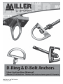
I298 Rev A / MFP9720186
3 January 2011
Table of Contents
1.0 General Requirements, Warnings and Limitations............................. 3-4
2.0 System Compatibility.......................................................................... 4
2.1 Miller Fall Protection Product Groups
3.0 Anchorage Connector Installation...................................................... 5-13
3.1 Mounted D-Ring Anchor (410)
3.2 D-Bolt Anchors (415, 416/417, 418/419)
3.3 Concrete D-Bolt Anchor (417C)
4.0 Inspection and Maintenance.............................................................. 14
Product Labels................................................................................... 39
Inspection and Maintenance Log....................................................... 40
Table des Matières
1.0 Exigences Générales, Avertissements et Limitations......................... 15-16
2.0 Compatibilité du Système................................................................... 16
2.1 Groupes de Produits Miller Fall Protection
3.0 Installation des Connecteurs D’ancrage............................................. 17-25
3.1 Ancrage à anneau en D (410)
3.2 Ancrage à boulon en D (415, 416/417, 418/419)
3.3 Ancrage à boulon en D pour béton (417C)
4.0 Inspection et Entretien....................................................................... 26
Étiquettes de Produit.......................................................................... 39
Registre D’inspection et D’entretien................................................... 40
Índice
1.0 Requisitos Generales, Advertencias y Limitaciones.......................... 27-28
2.0 Compatibilidad del Sistema............................................................... 28
2.1 Grupos de Productos Anticaídas Miller
3.0 Instalación de los Conectores de Anclaje.......................................... 29-37
3.1 Ancla de argolla “D” montada (410)
3.2 Ancla “D” de perno (415, 416/417, 418/419)
3.3 Ancla “D” de perno (417C)
4.0 Inspección y Mantenimiento.............................................................. 38
Etiquetas del Producto....................................................................... 39
Registro de Inspección y Mantenimiento........................................... 40
2
U s e r In s tru c ti o n s - E n g l i s h
Thank You
Thank you for your purchase of Miller Fall Protection equipment. Miller brand products are
SURGXFHGWRPHHWWKHKLJKHVWVWDQGDUGVRITXDOLW\DWRXU,62FHUWL¿HGIDFLOLW\0LOOHU)DOO
Protection equipment will provide you with years of use when cared for properly.
WARNING
All persons using this equipment must read, understand and follow
all instructions. Failure to do so may result in serious injury or death.
Do not use this equipment unless you are properly trained.
Questions?
CALL
1.800.873.5242
It is crucial that the authorized person/user of this fall protection equipment read and understand
these instructions. In addition, it is the employer’s responsibility to ensure that all users are
trained in the proper use, inspection, and maintenance of fall protection equipment. Fall protection training should be an integral part of a comprehensive safety program.
Proper use of fall arrest systems can save lives and reduce the potential of serious injuries from
a fall. The user must be aware that forces experienced during the arrest of a fall or prolonged
suspension may cause bodily injury. Consult a physician if there is any question about the
user’s ability to use this product. Pregnant women and minors must not use this product.
1.0 General Requirements,
Warnings and Limitations
All warnings and instructions shall be
provided to authorized persons/users.
All authorized persons/users must reference
the regulations governing occupational
safety, as well as applicable ANSI or
CSA standards. Please refer to product
ODEHOLQJIRULQIRUPDWLRQRQVSHFL¿F26+$
regulations, and ANSI and CSA standards
met by product.
Proper precautions should always be taken
to remove any obstructions, debris, material,
or other recognized hazards from the work
area that could cause injuries or interfere with
the operation of the system.
All equipment must be inspected before
each use according to the manufacturer’s
instructions.
All equipment should be inspected by a
TXDOL¿HGSHUVRQRQDUHJXODUEDVLV
To minimize the potential for accidental
disengagement, a competent person must
ensure system compatibility.
Equipment must not be altered in any
way. Repairs must be performed only by
the manufacturer, or persons or entities
authorized in writing by the manufacturer.
Any product exhibiting deformities, unusual
wear, or deterioration must be immediately
discarded.
Any equipment subject to a fall must be
removed from service.
The authorized person/user shall have
a rescue plan and the means at hand to
implement it when using this equipment.
Never use fall protection equipment for
purposes other than those for which it was
designed. Fall protection equipment should
never be used for towing or hoisting.
Equipment must not be exposed to
environmental hazards and chemicals which
may produce a harmful effect.
Use in a corrosive or caustic environment
dictates a more frequent inspection and
servicing program to ensure the integrity of
3 the product is maintained.
U s e r In s tru c ti o n s - E n g l i s h
Do not allow equipment to come in contact
with anything that will damage it including, but
not limited to, sharp, abrasive, rough or hightemperature surfaces, welding, heat sources,
electrical hazards, or moving machinery.
Always check for obstructions below the work
area to make sure potential fall path is clear.
Do not expose the equipment to any hazard
which it is not designed to withstand. Consult
the manufacturer in cases of doubt.
Never remove product labels, which include
important warnings and information for the
authorized person/user.
Allow adequate fall clearance below the work
surface.
2.0 System Compatibility
All Miller fall protection products are designed for use with Miller approved components.
Substitution or replacement with non-approved component combinations or subsystems or both
may affect or interfere with the safe function of each other and endanger the compatibility within
the system. This incompatibility may affect the reliability and safety of the total system.
2.1 Miller Fall Protection Product Groups
A comprehensive fall protection program must be viewed as a “total system” beginning with
KD]DUGLGHQWL¿FDWLRQDQGHQGLQJZLWKRQJRLQJPDQDJHPHQWUHYLHZ0LOOHU)DOO3URWHFWLRQYLHZV
its products as a “system within a system.” Three key components of the “Miller System” need to
be in place and properly used to provide maximum worker protection.
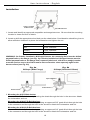
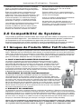
$$1&+2532,17$1&+25$*(&211(&725
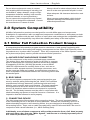
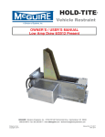
7KH¿UVWFRPSRQHQWLVWKHDQFKRUSRLQWDQFKRUDJHFRQQHFWRU
The anchor point, also referred to as the tie-off point, is a secure
point of attachment for connecting devices and must be capable
of supporting 5,000 lbs. (22.2kN) per worker or meet OSHA
1926.502 requirements for a safety factor of two, such as an
I-beam or other support structure. Anchorage connectors, such
as the cross-arm strap and eyebolt, are sometimes necessary to
make compatible connections between the connecting device and
the anchor point.
A
B
%%2'<:($5
The second system component is the personal protective gear
worn by workers while performing the job. Miller Fall Protection
manufactures full-body harnesses, positioning belts and body
EHOWVIRUXVHLQVSHFL¿FZRUNHQYLURQPHQWV)XOOERG\KDUQHVVHV
are engineered to aid in the arrest of a free fall and should be
worn in all situations where workers are exposed to a potential
free fall. The full-body harness must be used in conjunction with
shock-absorbing equipment to keep fall forces to a minimum. It is
imperative that the harness be worn properly.
&&211(&7,1*'(9,&(
The third component of the system is the connecting device. The most important feature
of the connecting device is the built-in shock absorber. Whether the connecting device is a
shock-absorbing lanyard or self-retracting lifeline, they are designed to dramatically reduce
fall arresting forces. Rope, web or cable lanyards being used for fall arrest MUST be used in
conjunction with a shock absorber (i.e., Miller SofStop pack).
Individually, none of these components will provide protection from a fall. Used properly
with each other, they form the “Miller System” and become a critically important part of
the “total fall protection system.”
4
C
U s e r In s tru c ti o n s - E n g l i s h
3.0 Anchorage Connector Installation
Installation Warnings, Limitations and Requirements
for All Anchorage Connectors
Before installation of any anchorage connector, carefully inspect to ensure that it is in
XVHDEOHFRQGLWLRQ&KHFNIRUPLVVLQJRUGDPDJHGSDUWV'RQRWXVHWKLVHTXLSPHQWLI
any component does not operate properly or if the unit appears to be damaged in any
ZD\5HIHUWRWKHLQVSHFWLRQVHFWLRQRIWKLVPDQXDO
2QO\WUDLQHGDQGFRPSHWHQWSHUVRQQHOVKRXOGLQVWDOODQGXVHWKLVHTXLSPHQW
(QVXUHWKDWWKHDQFKRUSRLQWLVDWDKHLJKWWKDWOLPLWVIUHHIDOOGLVWDQFHWRIWPRUOHVV
Always work directly under the anchor point to avoid a swing-fall injury.
(QVXUHWKDWWKHDQFKRUDJHFRQQHFWRULVDWDKHLJKWWKDWZLOOQRWDOORZDORZHUOHYHOWREH
VWUXFNVKRXOGDIDOORFFXU:KHQVHOHFWLQJDQDQFKRUDJHSRLQWDOZD\VUHPHPEHUWKDW
VKRFNDEVRUEHUVZLOOHORQJDWHZKHQVXEMHFWHGWRIDOODUUHVWIRUFHV5HIHUWRWKHODEHOVDQG
instructions provided with the connecting device to obtain the maximum elongation distance.
Fall arrest systems used with the anchorage connector must be rigged in accordance to
UHJXODWRU\UHTXLUHPHQWV>$OOLQVWUXFWLRQVDQGZDUQLQJVSURYLGHGZLWKWKHFRPSRQHQWVRI
the personal fall arrest system must be read, understood, and followed.]
Make sure that all connections within the fall arrest system are compatible.
7KHDQFKRUDJHFRQQHFWRUPXVWEHFRPSDWLEOHZLWKWKHVQDSKRRNRUFDUDELQHURIWKH
connecting device and must not be capable of causing a load to be applied to the gate/
keeper.
Use only locking carabiners, locking snap hooks or other Miller approved connectors or
FRQQHFWLQJGHYLFHVWRDWWDFKWRWKLVHTXLSPHQW
Never use an anchorage connector which will not allow snap hook or carabiner gate/
keeper to close.
$QDQFKRUDJHFRQQHFWRULVGHVLJQHG)2586(%<21(3(562121/<
All anchorage connectors included in this manual have a minimum tensile strength of
OEVN1
7KHVWUXFWXUHWKDWWKLVSURGXFWLVDWWDFKHGWRPXVWEHFDSDEOHRIVXSSRUWLQJDOE
N1VWDWLFORDGRUSURYLGHDVDIHW\IDFWRULQWKHGLUHFWLRQRISXOO
$QFKRUDJHUHTXLUHPHQWVEDVHGRQ$16,DUHDVIROORZV
)RUIDOODUUHVWV\VWHPVDQFKRUDJHVPXVWZLWKVWDQGDVWDWLFORDGRIOEVN1IRU
QRQFHUWL¿HGDQFKRUDJHVRUWZRWLPHVWKHPD[LPXPDUUHVWLQJIRUFHIRUFHUWL¿HGDQFKRUDJHV
)RUSRVLWLRQLQJV\VWHPVDQFKRUDJHVPXVWZLWKVWDQGDVWDWLFORDGRIOEVN1IRU
QRQFHUWL¿HGDQFKRUDJHVRUWZRWLPHVWKHIRUHVHHDEOHIRUFHIRUFHUWL¿HGDQFKRUDJHV
)RUWUDYHOUHVWUDLQWDQFKRUDJHVPXVWZLWKVWDQGDVWDWLFORDGRIOEVN1IRUQRQ
FHUWL¿HGDQFKRUDJHVRUWZRWLPHVWKHIRUHVHHDEOHIRUFHIRUFHUWL¿HGDQFKRUDJHV
)RUUHVFXHV\VWHPVDQFKRUDJHVPXVWZLWKVWDQGDVWDWLFORDGRIOEVN1IRUQRQ
FHUWL¿HGDQFKRUDJHVRU¿YHWLPHVWKHDSSOLHGORDGIRUFHUWL¿HGDQFKRUDJHV
:KHQPRUHWKDQRQHSHUVRQDOIDOODUUHVWV\VWHPLVDWWDFKHGWRDQDQFKRUDJHWKHDERYH
anchorage strengths must be multiplied by the number of personal fall arrest systems attached
to the anchorage.
0RXQWHG'5LQJ'%ROW$QFKRUVDQG&RQFUHWH'%ROW
$QFKRU&PHHW26+$DQG$16,$=>OEVNJ@
>Note: If the system is used by an employee having a combined tool and body weight
between 310 lbs. (140.6 kg) and 400 lbs. (181.4 kg), then the employer must appropriately
modify the criteria and protocols to provide proper protection for such heavier weights,
or the system will not be deemed to be in compliance with the requirements of OSHA
1926.502(d)(16).]
5
U s e r In s tru c ti o n s - E n g l i s h
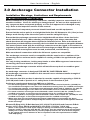
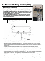
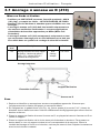
3.1 Mounted D-Ring Anchor (410)
Warnings and Limitations
)RUXVHE\21(SHUVRQRQO\0D[LPXPFDSDFLW\LVOEV
NJLQFOXGLQJWRROV²'2127(;&(('7+,6:(,*+7
8VHRQO\0LOOHUDSSURYHGEROWVDQGIDVWHQHUVZLWKWKHVHDQFKRUV
7KH0RXQWHG'5LQJ$QFKRUVKRXOGRQO\EHLQVWDOOHGRQKRUL]RQWDORYHUKHDGVXUIDFHV2WKHULQVWDOODWLRQDSSOLFDWLRQVPXVW
be approved by Miller Fall Protection.
7KH0RXQWHG'5LQJ$QFKRULVRQO\DSSURYHGDVDVLQJOH
user anchorage connector and should not be used within any
horizontal lifeline system.
Model No.
Description
Material
Weight
410
D-ring anchor with mounting bracket,
4 - 3/8” x 3-1/2” grade 5 bolts, 4 - 3/8”
nuts and 4 - 3/8” lockwashers
Drop Forge
Alloy Steel
1 lb. 9.6 oz.
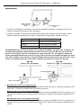
Anchorage/Structure
Mounting Bracket
Bolt Assembly
Installation
'5LQJ
1. Locate and identify an approved compatible anchorage/structure. Be sure that the mounting
location is clean and free of debris.
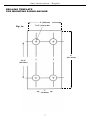
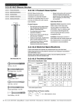
2. Using a copy of the template provided (see Fig. 1a), drill four (4) each 7/16” (11mm) diameter
KROHVLQWRWKHVWUXFWXUH&RQVLGHUDWLRQVKRXOGEHJLYHQWRDOORZVXI¿FLHQWFOHDUDQFHWRWLJKWHQDOO
bolts and nuts.
3. Place the mounting bracket through the D-ring, centering the D-ring bar on the bracket.
4. Position the mounting bracket over the pre-drilled holes in the structure. Install one bolt through
a hole in the bracket and through the corresponding hole in the structure. Place the lockwasher
and nut onto the bolt, but do not tighten completely. Repeat with remaining three bolts.
5. Completely tighten using a torque value between 20-25 ft. lbs. Ensure the entire nut is engaged
on the threads of each bolt, and the device is securely fastened to the structure.
WARNING: Do not overtighten. Excessive tension can cause damage to the anchorage
system.
Removal: Loosen and remove all nuts, lockwashers and bolts to remove D-ring and mounting
bracket from the anchorage/structure.
6
U s e r In s tru c ti o n s - E n g l i s h
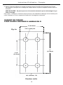
DRILLING TEMPLATE
FOR MOUNTING D-RING ANCHOR
PP
Fig. 1a
´PPGLD
PP
´
PP
´
PP
Full Scale
7
U s e r In s tru c ti o n s - E n g l i s h
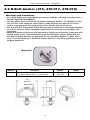
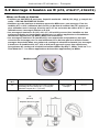
3.2 D-Bolt Anchor (415, 416/417, 418/419)
Warnings and Limitations
)RUXVHE\21(SHUVRQRQO\0D[LPXPFDSDFLW\LVOEVNJLQFOXGLQJWRROV²
'2127(;&(('7+,6:(,*+7
8VHRQO\0LOOHUDSSURYHGEROWVDQGIDVWHQHUVZLWKWKHVHDQFKRUV)RU0RGHOVDQG
WKHXVHUPXVWVXSSO\DQDSSURYHG´JUDGHEROWIRUXVHZLWKWKH'EROW
DQFKRURUDQDSSURYHG´JUDGHEROWIRUXVHZLWKWKH'EROWDQFKRU
7KHDQG'%ROW$QFKRUVPD\EHLQVWDOOHGRQRYHUKHDGKRUL]RQWDO
RUYHUWLFDOVXUIDFHV2WKHULQVWDOODWLRQDSSOLFDWLRQVPXVWEHDSSURYHGE\0LOOHU)DOO
Protection.
0RGHO'%ROW$QFKRUVDUHRQO\DSSURYHGDVVLQJOHXVHUDQFKRUDJHFRQQHFWRUVDQG
VKRXOGQRWEHXVHGDVHQGDQFKRUVLQDQ\KRUL]RQWDOOLIHOLQHV\VWHP0RGHO
DQG'%ROW$QFKRUVDUHDSSURYHGIRUXVHZLWK0LOOHU6N\*ULS0LOOHU7HFK/LQHDQG7LWDQ:HE/LQH+RUL]RQWDO/LIHOLQH6\VWHPV$Q\RWKHUDSSOLFDWLRQVPXVW
be Miller approved.
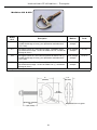
Model 415
Model No.
415
Description
One-piece D-bolt anchor with lockwasher and nut;
1/2” (13mm) diameter bolt; 1-1/4” (32mm) long
´
PP
´
PP
:DUQLQJ/DEHO
´
PP
8
Material
Weight
Drop Forge
Alloy Steel
12.8 oz
U s e r In s tru c ti o n s - E n g l i s h
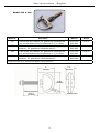
Model 416 & 418
Model No.
Material
Weight
416
D-bolt anchor with hardware (5/8” grade 8 bolt, lockwasher and
nut); accommodates working thicknesses up to 4” (101.6mm)
Description
Drop Forge
Alloy Steel
1 lb. 8 oz.
417*
D-bolt anchor without hardware (Note: User supplies mounting
hardware - 5/8” grade 8 bolt, lockwasher and nut.)
Drop Forge
Alloy Steel
14.7 oz.
418
D-bolt anchor with hardware (3/4” grade 8 bolt, lockwasher and
nut); accommodates working thicknesses up to 4” (101.6mm)
Drop Forge
Alloy Steel
1 lb. 8 oz.
419*
D-bolt anchor without hardware (Note: User supplies mounting
hardware - 3/4” grade 8 bolt, lockwasher and nut.)
Drop Forge
Alloy Steel
14.7 oz.
*Length of bolt may vary to accommodate different working thicknesses.
´
PP
´
PP
´
PP
:RUNLQJ7KLFNQHVV
XSWR´
PP
:DUQLQJ/DEHO
9
U s e r In s tru c ti o n s - E n g l i s h
Installation
'%ROW$QFKRU
'%ROW$QFKRU
1. Locate and identify an approved compatible anchorage/structure. Be sure that the mounting
location is clean and free of debris.
2. Locate or drill the appropriate sized hole per the chart below. Consideration should be given to
DOORZVXI¿FLHQWFOHDUDQFHWRSODFHWKHORFNZDVKHUDQGWLJKWHQWKHQXW
Model
+ROH6L]H
415
17/32” diameter
416/417
21/32” diameter
418/419
25/32” diameter
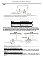
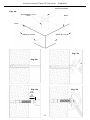
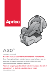
WARNING: On D-bolts installed to W-Shaped beams, the mounting hole must be drilled
SHUSHQGLFXODUWRWKHÀDQJHVHH)LJD'EROWVLQVWDOOHGWR66KDSHGEHDPVPXVWEH
GULOOHGSHUSHQGLFXODUWRWKHÀDQJHDQGDWDSHUHGDNDEHYHOVLGHKLOORUZHGJHZDVKHU
must be used to ensure the D-bolt and/or nut and washer seats squarely against the
EHDPVXUIDFHVHH)LJE
Fig. 2a
:6KDSH:LGH)ODQJH
Fig. 2b
66KDSH6WUXFWXUDO,%HDP
7DSHUHG:DVKHU
'%ROW$QFKRU
'%ROW$QFKRU
3. 0RXQWLQJWKH'%ROW$QFKRU
Mount the 415 D-Bolt Anchor by inserting the shank through the hole in the structure. Attach
the lockwasher and nut.
0RXQWLQJWKH'%ROW$QFKRUV
Mount the 416/417 D-Bolt Anchor by passing an approved 5/8” grade 8 bolt through the hole
in the connector and through the hole in the structure. Attach the lockwasher and nut.
0RXQWLQJWKH'%ROW$QFKRUV
Mount the 418/419 D-Bolt Anchor by passing an approved 3/4” grade 8 bolt through the hole
in the connector and through the hole in the structure. Attach the lockwasher and nut.
10
U s e r In s tru c ti o n s - E n g l i s h
4. Completely tighten using the recommended torque value per chart below. Ensure the entire
nut is engaged on the threads, and the device is securely fastened to the structure.
Model
7RUTXH9DOXHV
415
45-55 ft. lbs.
416/417
125 ft. lbs.
418/419
185-195 ft. lbs.
WARNING: Do not overtighten. Excessive tension can cause damage to the anchorage
system.
Removal: Loosen and detach the nut and washer. Then remove D-Bolt Anchor from the anchorage/structure.
11
U s e r In s tru c ti o n s - E n g l i s h
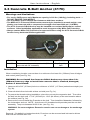
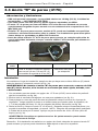
3.3 Concrete D-Bolt Anchor (417C)
Warnings and Limitations
)RUXVHE\21(SHUVRQRQO\0D[LPXPFDSDFLW\LVOEVNJLQFOXGLQJWRROV²
'2127(;&(('7+,6:(,*+7
8VHRQO\0LOOHUDSSURYHGEROWVDQGIDVWHQHUVZLWKWKHVHDQFKRUV
7KH0LOOHU&&RQFUHWH'%ROW$QFKRUPXVWRQO\EHLQVWDOOHGWRQRUPDOZHLJKWFRPSOHWHO\FXUHGFRQFUHWHZLWKDFRPSUHVVLYHVWUHQJWKRIDWOHDVWSVL03D
7KH&&RQFUHWH'%ROW$QFKRUPD\EHLQVWDOOHGRQRYHUKHDGKRUL]RQWDORUYHUWLFDO
VXUIDFHV2WKHULQVWDOODWLRQDSSOLFDWLRQVPXVWEHDSSURYHGE\0LOOHU)DOO3URWHFWLRQ
$OZD\VFRQWDFW0LOOHU)DOO3URWHFWLRQIRUDSSURYDOEHIRUHXVLQJWKH&&RQFUHWH'%ROW
Anchor in any horizontal lifeline application.
Model No.
Description
Material
Weight
417C
D-bolt anchor with concrete expansion bolt (5/8" x 6"
anchor bolt with 5/8" lockwasher)
Drop Forge Alloy
Steel
1 lb. 4 oz.
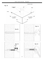
Installation
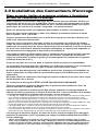
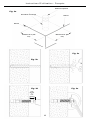
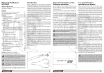
When considering location, ensure there is a minimum of at least 9 in. (228mm) from all edges
and control joints (see Fig. 3a).
WARNING: Do not install the Concrete D-Bolt Anchor any closer than 9 in.
(228mm) from any edge or install into concrete that is cracked, damaged,
broken or deteriorated.
1. Hammer drill a 5/8” (15.9mm) hole to a minimum of 4-5/8” (117.5mm) embedment depth (see
Fig. 3b).
2. Clean all debris from hole with a blow out bulb (see Fig. 3c).
3. To protect the threads during installation, place the nut onto the expansion bolt. Then drive
the bolt into the hole until 1-7/16" (36.5mm) to 1-3/4" (44.45mm) of the stud remains above
the surface (see Fig. 3d).
5HPRYHWKHQXWDQGLQVWDOOWKH'DQFKRUWRWKHEROW7KHQLQVWDOOWKHÀDWZDVKHUIROORZHGE\
the lockwasher and nut. NOTE: A minimum of 2 threads should protrude past the nut after
assembly. Torque to between 80-85 ft. lbs. (see Fig. 3e).
WARNING: Do not overtighten. Excessive tension can cause damage to the anchorage
system.
Removal: If installed in a bottomless hole, D-anchor can be removed and bolt can be driven
ÀXVKZLWKWKHVXUIDFHDIWHUXVH
12
U s e r In s tru c ti o n s - E n g l i s h
([SDQVLRQ%ROW
Fig. 3a
(PEHGPHQW
'HSWK
(GJH
(GJH
LQPP
Minimum
LQPP
Minimum
Fig. 3c
Fig. 3b
Fig. 3d
Fig. 3e
PP
to
PP
13
U s e r In s tru c ti o n s - E n g l i s h
4.0 Inspection and Maintenance
Inspection
Miller Anchorage Connectors are designed for today’s rugged work environments. To maintain
their service life and high performance, all components should be inspected frequently.
Anchorage connectors must be visually inspected by the user before each use and
inspected by a Competent Person on a regular basis.
Inspect product for any of the following: bent, cracked, distorted, worn, malfunctioning or
damaged parts; loose fasteners or missing parts/components; deterioration; deformation;
corrosion; signs that indicate the product has been subjected to a fall arrest; or any other
indications of damage/problems that may affect the integrity and operation of the product. If in
doubt, contact the manufacturer.
Devices that do not pass inspection
or have been subjected to fall arresting forces
must be removed from service.
Cleaning and Storage
Basic care of all Miller Fall Protection equipment will prolong the life of the unit and will contribute toward the performance of its vital safety function. Periodically clean the device to remove
any dirt, paint, corrosives, contaminants, or other materials that may have accumulated. When
not in use, store in a clean, dry area, free of exposure to furmes or corrosive elements.
Servicing
Servicing of Miller Fall Protection equipment must only be carried out by Miller Fall Protection
or persons or entities authorized in writing by Miller Fall Protection. A record log of all servicing
and inspection dates for this device must be maintained. Only original Miller replacement parts
are approved for use in this device. Non-repairable devices that do not pass inspection must be
disposed of in a manner to prevent inadvertent further use. Contact Miller Technical Services at
800.873.5242 if you have any questions.
14
Instructions D’utilisation - Français
Merci
Nous désirons vous remercier d’avoir acheté un équipement de Miller Fall Protection. Les produits
de marque Miller sont fabriqués selon des normes de qualité des plus rigoureuses, dans notre usine
FHUWL¿pH,62%LHQHQWUHWHQXXQpTXLSHPHQW0LOOHU)DOO3URWHFWLRQV¶XWLOLVHGHVDQQpHVGXUDQW
AVERTISSEMENT
Toutes les personnes qui utilisent cet équipement doivent lire, comprendre et suivre toutes les instructions. Tout manquement à cette règle
peut avoir pour conséquence des blessures graves ou la mort. Ne pas
utiliser cet équipement à moins d’avoir reçu une formation adéquate.
Des Questions?
APPELEZ
1.800.873.5242
Il est essentiel que la personne autorisée à utiliser cet équipement de protection contre les
chutes lise et comprenne ces instructions. De plus, il incombe à l’employeur de s’assurer
que tous les utilisateurs sont formés à l’emploi, à l’inspection et à l’entretien adéquats de
l’équipement de protection contre les chutes. La formation sur la protection contre les chutes
devrait faire partie intégrante d’un programme global de sécurité.
L’utilisation adéquate de systèmes d’arrêt de chute peut épargner des vies et réduire le risque
de blessures graves consécutives à une chute. L’utilisateur doit être sensibilisé au fait que les
forces subies lors d’un arrêt de chute ou d’une suspension prolongée peuvent causer des blessures corporelles. Dans l’incertitude sur la capacité de la personne à utiliser ce produit, consulter
un médecin. Les femmes enceintes et les mineurs ne doivent pas utiliser ce produit.
1.0 Exigences Générales,
Avertissements et Limitations
,OHVWLQWHUGLWGHPRGL¿HUO¶pTXLSHPHQWGH
quelque façon que ce soit.
Les avertissements et instructions devront être
mis à la disposition des personnes/utilisateurs
autorisés.
Les réparations doivent être effectuées
uniquement par le fabricant de l’équipement,
ou par des personnes ou entités autorisées par
écrit par le fabricant.
/HVSHUVRQQHVXWLOLVDWHXUVDXWRULVpV
GRLYHQWVHUHSRUWHUjODUpJOHPHQWDWLRQ
DSSOLFDEOHHQPDWLqUHGHVpFXULWpHQPLOLHX
GHWUDYDLODLQVLTX¶DX[QRUPHV$16,RX
&6$SHUWLQHQWHV9HXLOOH]YRXVUHSRUWHU
DX[pWLTXHWWHVDSSRVpHVVXUOHVSURGXLWV
SRXUGHVLQIRUPDWLRQVSOXVGpWDLOOpHVVXU
OHVUqJOHPHQWV26+$DLQVLTXHOHVQRUPHV
$16,HW&6$DX[TXHOOHVFHVSURGXLWVVRQW
conformes.
Tout produit déformé, anormalement usé ou
détérioré doit être immédiatement mis au rebut.
Tout équipement soumis à une chute doit être
mis hors service.
L’utilisateur doit posséder un plan de sauvetage
et avoir les moyens de le mettre en œuvre
lorsqu’il utilise cet équipement.
'HVSUpFDXWLRQVGRLYHQWrWUHSULVHVD¿QG¶pOLPLQHU
de la zone de travail les obstacles, débris,
matériaux ou autres éléments présentant un
danger et qui pourraient causer des blessures ou
nuire au bon fonctionnement du système.
Ne jamais utiliser un équipement de protection
contre les chutes dans un but autre que celui
pour lequel il a été prévu. Ne jamais utiliser un tel
équipement pour remorquer ou lever une charge.
L’équipement doit être inspecté avant chaque
utilisation selon les directives du fabricant.
Ne pas exposer le matériel à des risques
environnementaux ni à des produits chimiques
susceptibles de produire un effet nuisible.
L’équipement doit être régulièrement inspecté par
XQHSHUVRQQHTXDOL¿pH
Pour minimiser le risque de décrochage
accidentel, une personne compétente doit
s’assurer de la compatibilité du système.
15
Instructions D’utilisation - Français
L’utilisation dans un milieu corrosif ou caustique
exige un programme d’inspection et d’entretien
plus fréquent pour maintenir l’intégrité du produit.
Ne pas exposer le matériel à tout risque pour
lequel il n’est pas conçu. En cas de doute,
consulter le fabricant.
Éviter tout contact entre un équipement et un
objet susceptible de l’endommager, incluant
notamment, sans que la liste soit exhaustive : des
arêtes vives, une surface abrasive, rugueuse ou
à haute température, du matériel de soudage,
une source de chaleur, un appareil électrique
présentant un danger ou une machine mobile.
7RXMRXUVYpUL¿HUTX¶LOQ¶\DSDVG¶REVWDFOHVHQ
dessous de la zone de travail et que le trajet en
cas de chute est dégagé.
Les matériaux synthétiques doivent être protégés
contre le laitier (de soudure), les étincelles
FKDXGHVOHVÀDPPHVQXHVRXDXWUHVVRXUFHV
de chaleur. Dans de tels cas, on recommande
d’utiliser des matériaux résistant à la chaleur.
3UpYRLUXQHGLVWDQFHGHGpJDJHPHQWVXI¿VDQWH
en dessous de la surface de travail.
Ne jamais ôter une étiquette apposée sur un
produit; des informations et avertissements
importants y sont en effet inscrits à l’intention de
la personne/de l’utilisateur autorisé.
2.0 Compatibilité du Système
Les produits de protection antichute Miller sont conçus pour être utilisés en conjonction avec des
composants Miller approuvés. Les substitutions ou les remplacements par des combinaisons
de composants ou de sous-systèmes non approuvés peuvent nuire à leur sécurité de
fonctionnement réciproque et ainsi remettre en cause la compatibilité des éléments du système.
&HWWHLQFRPSDWLELOLWpSHXWQXLUHjODVpFXULWpHWjOD¿DELOLWpGHO¶HQVHPEOHGXV\VWqPH
2.1 Groupes de Produits Miller Fall Protection
Un programme complet de protection contre les chutes doit être considéré comme un « système
WRWDOªGpEXWDQWSDUXQHLGHQWL¿FDWLRQGHVULVTXHVHWVHWHUPLQDQWSDUXQHUHYXHGHODGLUHFWLRQ
cette revue doit avoir lieu en permanence. Pour Miller Fall Protection, ces produits représentent
un « système dans un système ». Une protection maximale du travailleur passe par la mise en
place et l’utilisation adéquate de trois composants clés du « système Miller ».
A. POINT D’ANCRAGE/CONNECTEUR D’ANCRAGE
Le premier composant est le point d’ancrage/connecteur d’ancrage. Le point
G¶DQFUDJHpJDOHPHQWGpQRPPpSRLQWGH¿[DWLRQFRQVWLWXHXQSRLQWG¶DWWDFKH
sécuritaire des dispositifs de connexion et il doit pouvoir supporter 5000 lb (22.2
kN) par travailleur ou satisfaire aux exigences 1926.502 de l’OSHA, avec une
marge de sécurité de 2, comme une poutre en I ou autre structure de supportage.
Il est parfois nécessaire d’utiliser des connecteurs d’ancrage, comme la sangle
WUDQVYHUVDOHHWOHERXORQj°LOD¿QGHUpDOLVHUGHVFRQQH[LRQVFRPSDWLEOHVHQWUH
le dispositif de connexion et le point d’ancrage.
A
B
B. ÉQUIPEMENT DE PROTECTION INDIVIDUELLE
L’équipement de protection individuelle porté par les travailleurs dans
l’accomplissement de leurs tâches constitue le second composant. Miller Fall
Protection fabrique des harnais de sécurité complets, des ceintures de maintien
au travail et des ceintures de travail pour utilisation dans des conditions (de travail)
bien précises. Un harnais de sécurité complet est étudié pour l’arrêt d’une chute
libre et doit être porté par tout travailleur exposé à un risque de chute. Un harnais
de sécurité complet doit être utilisé en même temps qu’un absorbeur d’énergie
D¿QGHUpGXLUHDXPLQLPXPOHVIRUFHVSUpVHQWHVHQFDVGHFKXWH,OHVWHVVHQWLHO
de porter le harnais de la bonne manière.
C. DISPOSITIF DE CONNEXION
Le dispositif de connexion constitue le dernier composant du système. L’élément le plus important du
dispositif de connexion est l’absorbeur d’énergie incorporé. Que le dispositif soit une corde d’amarrage
à absorbeur d’énergie ou un cordage de sécurité à rétraction automatique, il a été conçu pour réduire
substantiellement les forces mises en jeu lors de l’arrêt d’une chute. Une corde d’amarrage constituée
par une corde, une sangle ou un câble et servant de dispositif antichute DOIT ÊTRE utilisé en même
temps qu’un absorbeur d’énergie (par exemple: enveloppe compacte SofStop de Miller).
Aucun de ces composants ne peut assurer à lui seul une protection contre les chutes. Utilisés comme un tout, ces composants forment le « système Miller » et constituent une partie
du « système total de protection contre les chutes », système d’une importance vitale.
16
C
Instructions D’utilisation - Français
3.0 Installation des Connecteurs D’ancrage
Mises en garde, limites et exigences relatives à l’installation
de tous les connecteurs d’ancrage
$YDQWG¶LQVWDOOHUXQFRQQHFWHXUG¶DQFUDJHELHQV¶DVVXUHUTX¶LOHVWXWLOLVDEOH9pUL¿HUV¶LO
PDQTXHGHVSLqFHVRXV¶LO\HQDG¶DEvPpHV1HSDVVHVHUYLUGHO¶pTXLSHPHQWVLO¶XQGHV
FRPSRVDQWVQHIRQFWLRQQHSDVDGpTXDWHPHQWRXVLO¶pOpPHQWVHPEOHDEvPpG¶XQHIDoRQ
TXHOFRQTXH6HUHSRUWHUjODVHFWLRQ©,QVSHFWLRQªGXSUpVHQWPDQXHO
6HXOHXQHSHUVRQQHIRUPpHHWFRPSpWHQWHSHXWLQVWDOOHUHWXWLOLVHUFHWpTXLSHPHQW
6¶DVVXUHUTXHOHSRLQWG¶DQFUDJHVHVLWXHjXQHKDXWHXUTXLOLPLWHODGLVWDQFHGHFKXWH
OLEUHjSLHGVPRXPRLQV
7RXMRXUVPDQ°XYUHUGLUHFWHPHQWVRXVOHSRLQWG¶DQFUDJHSRXUpYLWHUGHVHEOHVVHUSDU
VXLWHG¶XQHFKXWHSDUEDODQFHPHQW
6¶DVVXUHUTXHOHFRQQHFWHXUG¶DQFUDJHVHVLWXHjXQHKDXWHXUTXLHPSrFKHGHGRQQHU
FRQWUHXQQLYHDXLQIpULHXUHQFDVGHFKXWH'DQVOHFKRL[G¶XQSRLQWG¶DQFUDJHQHMDPDLV
RXEOLHUTXHOHVDPRUWLVVHXUVGHFKRFVV¶pWLUHQWORUVTX¶LOVVRQWVRXPLVjGHVIRUFHVG¶DUUrW
GHFKXWH3RXUFRQQDvWUHODGLVWDQFHPD[LPDOHG¶pORQJDWLRQVHUHSRUWHUDX[pWLTXHWWHVHW
aux instructions accompagnant le dispositif de raccordement.
/HVV\VWqPHVG¶DUUrWGHFKXWHXWLOLVpVDYHFOHFRQQHFWHXUG¶DQFUDJHGRLYHQWrWUHpTXLSpV
FRQIRUPpPHQWDX[H[LJHQFHVUpJOHPHQWDLUHV>2QGRLWOLUHFRPSUHQGUHHWREVHUYHU
WRXWHVOHVLQVWUXFWLRQVHWPLVHVHQJDUGHTXLDFFRPSDJQHQWOHVFRPSRVDQWVGXV\VWqPH
LQGLYLGXHOG¶DUUrWGHFKXWH@
6¶DVVXUHUTXHWRXVOHVUDFFRUGVGDQVOHV\VWqPHG¶DUUrWGHFKXWHVRQWFRPSDWLEOHV
/HFRQQHFWHXUG¶DQFUDJHGRLWrWUHFRPSDWLEOHDYHFODERXFOHjSUHVVLRQRXOHPRXVTXHWRQ
GXGLVSRVLWLIGHUDFFRUGHPHQWVDQVTXHOHORTXHWVRLWVRXPLVjXQHFKDUJH
1¶XWLOLVHUTXHGHVPRXVTXHWRQVYHUURXLOODEOHVGHVERXFOHVjSUHVVLRQYHUURXLOODEOHVRX
DXWUHVFRQQHFWHXUVRXGLVSRVLWLIVGHUDFFRUGHPHQWDSSURXYpVGH0LOOHUSRXU¿[HUjFHW
pTXLSHPHQW
1HMDPDLVXWLOLVHUGHFRQQHFWHXUG¶DQFUDJHTXLHPSrFKHODERXFOHjSUHVVLRQRXOHORTXHW
GHPRXVTXHWRQGHVHIHUPHU
8QFRQQHFWHXUG¶DQFUDJHGRLWÇ75(87,/,6e3$581(6(8/(3(56211(
7RXVOHVFRQQHFWHXUVG¶DQFUDJH¿JXUDQWGDQVOHSUpVHQWPDQXHORIIUHQWXQHIRUFHGH
WUDFWLRQPLQLPDOHGHOEN1
/DVWUXFWXUHjODTXHOOHFHSURGXLWHVW¿[pGRLWSRXYRLUVXSSRUWHUXQHFKDUJHVWDWLTXHGH
OEN1RXSUpVHQWHUXQIDFWHXUGHVpFXULWpGHGDQVODGLUHFWLRQGHODWUDFWLRQ
/HVH[LJHQFHV$16,TXLV¶DSSOLTXHQWDX[DQFUDJHVVRQWOHVVXLYDQWHV
/¶DQFUDJHQRQFHUWL¿pG¶XQGLVSRVLWLIDQWLFKXWHGRLWVXSSRUWHUXQHFKDUJHVWDWLTXHGHOEN1WDQGLV
TX¶XQDQFUDJHFHUWL¿pGRLWVXSSRUWHUGHX[IRLVODIRUFHPD[LPDOHPLVHHQMHXORUVGHO¶DUUrWG¶XQHFKXWH
'DQVOHFDVG¶XQGLVSRVLWLIGHPDLQWLHQO¶DQFUDJHQRQFHUWL¿pGRLWVXSSRUWHUXQHFKDUJHVWDWLTXHGHOE
N1WDQGLVTX¶XQDQFUDJHFHUWL¿pGRLWVXSSRUWHUGHX[IRLVODIRUFHSUpYLVLEOH
'DQVOHFDVG¶XQHOLPLWDWLRQGHGpSODFHPHQWO¶DQFUDJHQRQFHUWL¿pGRLWVXSSRUWHUXQHFKDUJHVWDWLTXHGH
OEN1WDQGLVTX¶XQDQFUDJHFHUWL¿pGRLWVXSSRUWHUGHX[IRLVODIRUFHSUpYLVLEOH
/¶DQFUDJHXWLOLVpGDQVXQV\VWqPHVHUYDQWDXVDXYHWDJHGRLWVXSSRUWHUXQHFKDUJHVWDWLTXHGHOE
N1V¶LOQ¶HVWSDVFHUWL¿pRXGHFLQTIRLVODFKDUJHDSSOLTXpHV¶LOHVWFHUWL¿p
/RUVTXHSOXVLHXUVGLVSRVLWLIVDQWLFKXWHLQGLYLGXHOVVRQW¿[pVjXQPrPHDQFUDJHOHVUpVLVWDQFHVG¶DQFUDJHFL
dessus doivent être multipliées par le nombre de dispositifs anti-chute rattachés à l’ancrage.
/HVDQFUDJHVjDQQHDXHQ'jERXORQHQ'HWO¶DQFUDJHj
ERXORQHQ'SRXUEpWRQ&UpSRQGHQWDX[H[LJHQFHV26+$HW$16,$HW=
>OENJ@
>Nota : Si le système est utilisé par un employé ayant un poids combiné (outil et corps)
HQWUHOENJHWOENJO¶HPSOR\HXUGRLWDORUVPRGL¿HUDGpTXDWHPHQWOHV
FULWqUHVHWSURWRFROHVD¿QG¶DVVXUHUXQHSURWHFWLRQDGpTXDWHSRXUGHWHOVSRLGVVXSpULHXUV
sinon le système ne sera pas réputé conforme aux exigences de l’OSHA 1926.502(d)(16).]
17
Instructions D’utilisation - Français
3.1 Ancrage à anneau en D (410)
Mises en Garde et Limites
¬XWLOLVHUSDU81(6(8/(SHUVRQQH&DSDFLWpPD[LPDOHOE
NJ\FRPSULVOHVRXWLOV±1(3$6(;&e'(5&(32,'6
1¶XWLOLVHUTXHGHVERXORQVHWDWWDFKHVDSSURXYpV0LOOHUDYHFFHV
ancrages.
/¶DQFUDJHjDQQHDXHQ'GRLWrWUHLQVWDOOpXQLTXHPHQWVXU
GHVVXUIDFHVVXUpOHYpHVKRUL]RQWDOHV/HVDXWUHVDSSOLFDWLRQV
G¶LQVWDOODWLRQGRLYHQWrWUHDSSURXYpHVSDU0LOOHU0LOOHU)DOO
3URWHFWLRQ
/¶DQFUDJHjDQQHDXHQ'HVWDSSURXYpXQLTXHPHQWHQWDQW
TXHFRQQHFWHXUG¶DQFUDJHSRXUXQVHXOXWLOLVDWHXUHWQHGRLWSDV
rWUHXWLOLVpGDQVXQV\VWqPHGHFRUGDJHGHVpFXULWpKRUL]RQWDO
Modèle
de nº
Description
Matériel
Poids
410
Ancrage à anneau en D avec support
de ¿xation, 4 boulons de calibre 5
(3/8" x 3½"), 4 écrous (3/8") et 4
rondelles de blocage de 3/8"
Acier
d’alliage
estampé
1 lb. 9.6 oz.
Ancrage/structure
(QVHPEOHGHERXORQ
Pose
6XSSRUWGH¿[DWLRQ
$QQHDXHQ'
5HSpUHUHWLGHQWL¿HUXQDQFUDJHXQHVWUXFWXUHFRPSDWLEOHVDSSURXYpV6¶DVVXUHUTXH
O¶HPSODFHPHQWGHOD¿[DWLRQHVWSURSUHHWH[HPSWGHGpEULV
2. En s’alignant sur le gabarit fourni (voir Fig. 1a), percer quatre (4) trous de 7/16" (11mm) de
GLDPqWUHFKDFXQGDQVODVWUXFWXUH$OORXHUVXI¿VDPPHQWGHGpJDJHPHQWSRXUVHUUHUWRXVOHV
boulons et écrous.
3ODFHUOHVXSSRUWGH¿[DWLRQjWUDYHUVO¶DQQHDXHQ'HQSODoDQWODEDUUHGHO¶DQQHDXHQ'DX
centre du support.
3ODFHUOHVXSSRUWGH¿[DWLRQYLVjYLVOHVWURXVSUpIRUpVGDQVODVWUXFWXUH)DLUHSDVVHUXQ
boulon dans un trou du support et dans le trou correspondant de la structure. Placer la
rondelle de blocage et l’écrou sur le boulon, mais ne pas serrer à fond. Répéter la manœuvre
avec les trois boulons restants.
18
Instructions D’utilisation - Français
5. Serrer à fond en utilisant un couple de serrage entre 20 et 25 pi-lb. S’assurer que l’écrou
HVWHQJDJpDXFRPSOHWVXUOH¿OHWDJHGHFKDTXHERXORQHWTXHOHGLVSRVLWLIHVWELHQ¿[pjOD
structure.
MISE EN GARDE : Ne pas trop serrer. Une tension excessive peut endommager le système d’ancrage.
Pour retirer : Desserrer et enlever tous les écrous, les rondelles de blocage et les boulons pour
UHWLUHUO¶DQQHDXHQ'HWOHVXSSRUWGH¿[DWLRQGHO¶DQFUDJHGHODVWUXFWXUH
GABARIT DE FORAGE
POUR POSER L’ANCRAGE À ANNEAU EN D
PP
Fig. 1a
´PPGLD
PP
´
PP
´
PP
*UDQGHXUUpHOOH
19
Instructions D’utilisation - Français
3.2 Ancrage à boulon en D (415, 416/417, 418/419)
Mises en Garde et Limites
¬XWLOLVHUSDU81(6(8/(SHUVRQQH&DSDFLWpPD[LPDOHOENJ\FRPSULVOHV
RXWLOV±1(3$6(;&e'(5&(32,'6
1¶XWLOLVHUTXHGHVERXORQVHWDWWDFKHVDSSURXYpV0LOOHUDYHFFHVDQFUDJHV3RXUOHV
PRGqOHVHWO¶XWLOLVDWHXUGRLWIRXUQLUXQERXORQGHFDOLEUHGHDSSURXYp
SRXUXWLOLVDWLRQDYHFO¶DQFUDJHjERXORQHQ'RXXQERXORQGHFDOLEUHGHôSRXU
XWLOLVDWLRQDYHFO¶DQFUDJHjERXORQHQ'
/HVDQFUDJHVjERXORQHQ'HWSHXYHQWrWUHLQVWDOOpVVXUGHV
VXUIDFHVYHUWLFDOHVRXKRUL]RQWDOHVVXUpOHYpHV/HVDXWUHVDSSOLFDWLRQVG¶LQVWDOODWLRQ
GRLYHQWrWUHDSSURXYpHVSDU0LOOHU0LOOHU)DOO3URWHFWLRQ
/HVDQFUDJHVjERXORQHQ'PRGqOHVRQWDSSURXYpVXQLTXHPHQWHQWDQWTXH
FRQQHFWHXUVG¶DQFUDJHSRXUXQVHXOXWLOLVDWHXUHWQHGRLYHQWSDVrWUHXWLOLVpVFRPPH
DQFUDJHVG¶H[WUpPLWpGDQVXQV\VWqPHGHFRUGDJHGHVpFXULWpKRUL]RQWDO/HVDQFUDJHV
jERXORQHQ'PRGqOHVHWVRQWDSSURXYpVSRXUrWUHXWLOLVpVDYHF
OHVV\VWqPHVGHFRUGDJHGHVpFXULWpKRUL]RQWDX[0LOOHU6N\*ULS0LOOHU7HFK/LQHHW
7LWDQ:HE/LQH/HVDXWUHVDSSOLFDWLRQVGRLYHQWrWUHDSSURXYpHVSDU0LOOHU
Modèle 415
Modèle
de nº
415
Description
Ancrage monobloc à boulon en D avec rondelle
de blocage et écrou; boulon de ½" (13 mm) de
diamètre; longueur de 1¼" (32 mm)
´
PP
´
PP
eWLTXHWWHGHPLVHHQJDUGH
´
PP
20
Matériel
Poids
Acier d’alliage
estampé
12.8 oz
Instructions D’utilisation - Français
Modèles 416 & 418
Modèle
de nº
Description
Matériel
Poids
416
Ancrage à boulon en D avec ferrures (boulon de calibre 8 de 5/8",
rondelle de blocage et écrou); pour épaisseurs maximales de 4"
(101,6 mm)
Acier d’alliage
estampé
1 lb. 8 oz.
417*
Ancrage à boulon en D sans ferrures (Nota : l’utilisateur fournit
les ferrures de montage – boulon de calibre 8 de 5/8", rondelle de
blocage et écrou.)
Acier d’alliage
estampé
14.7 oz.
418
Ancrage à boulon en D avec ferrures (boulon de calibre 8 de ¾",
rondelle de blocage et écrou); pour épaisseurs maximales de 4"
(101,6 mm)
Acier d’alliage
estampé
1 lb. 8 oz.
419*
Ancrage à boulon en D sans ferrures (Nota : l’utilisateur fournit
les ferrures de montage – boulon de calibre 8 de ¾", rondelle de
blocage et écrou.)
Acier d’alliage
estampé
14.7 oz.
*La longueur du boulon peut varier selon les différentes épaisseurs.
´
PP
´
PP
´
PP
eSDLVVHXUPD[LPDOH
GH
PP
eWLTXHWWHGHPLVHHQJDUGH
21
Instructions D’utilisation - Français
Pose
Ancrage à boulon
HQ'
$QFUDJHj
ERXORQHQ'
5HSpUHUHWLGHQWL¿HUXQDQFUDJHXQHVWUXFWXUHFRPSDWLEOHVDSSURXYpV6¶DVVXUHUTXH
O¶HPSODFHPHQWGHOD¿[DWLRQHVWSURSUHHWH[HPSWGHGpEULV
2. Repérer ou percer un trou de dimension appropriée selon le tableau ci-dessous. Allouer suf¿VDPPHQWGHGpJDJHPHQWSRXUSODFHUODURQGHOOHGHEORFDJHHWVHUUHUO¶pFURX
Modèle
'LPHQVLRQVGXWURX
415
17/32" de diamètre
416/417
21/32" de diamètre
418/419
25/32" de diamètre
MISE EN GARDE : Sur les boulons en D posés à des poutres en forme de W, percer le
WURXGHPRQWDJHSHUSHQGLFXODLUHPHQWjODEULGHYRLU)LJD3RXUOHVERXORQVHQ'SRsés à des poutres en forme de S, percer le trou perpendiculairement à la bride et utiliser
une rondelle conique (c.-à-d biseautée, déviée ou à coin) pour que le boulon en D et/ou
O¶pFURXHWODURQGHOOHUHSRVHQWFDUUpPHQWVXUODVXUIDFHGHODSRXWUHYRLU)LJE
Fig. 2a
(QIRUPHGH:EULGHODUJH
Fig. 2b
(QIRUPHGH6SRXWUHSRUWHXVHHQ,
5RQGHOOHFRQLTXH
$QFUDJHjERXORQHQ'
Ancrage à boulon
HQ'
3. 0RQWDJHGHO¶DQFUDJHjERXORQHQ'
0RQWHUO¶DQFUDJHjERXORQHQ'HQLQVpUDQWODSDUWLH¿OHWpHGDQVOHWURXGHODVWUXFWXUH
Fixer la rondelle de blocage et l’écrou.
0RQWDJHGHVDQFUDJHVjERXORQHQ'
Monter l’ancrage à boulon en D 416/417 en faisant passer un boulon approuvé de calibre 8
de 5/8" dans le trou du connecteur et dans celui de la structure. Fixer la rondelle de blocage
et l’écrou.
0RQWDJHGHVDQFUDJHVjERXORQHQ'
Monter l’ancrage à boulon en D 418/419 en faisant passer un boulon approuvé de calibre 8
de ¾" dans le trou du connecteur et dans celui de la structure. Fixer la rondelle de blocage et
l’écrou.
22
Instructions D’utilisation - Français
4. Serrer à fond suivant le couple de serrage recommandé dans le tableau ci-dessous. S’assurer
TXHO¶pFURXHVWHQJDJpjIRQGVXUOH¿OHWDJHHWTXHOHGLVSRVLWLIHVWELHQ¿[pjODVWUXFWXUH
Modèle
Couples de serrage
415
45-55 ft. lbs.
416/417
125 ft. lbs.
418/419
185-195 ft. lbs.
MISE EN GARDE : Ne pas trop serrer. Une tension excessive peut endommager le système d’ancrage.
Pour retirer : Desserrer et enlever l’écrou et la rondelle. Puis retirer l’ancrage à boulon en D de
la structure d’ancrage.
23
Instructions D’utilisation - Français
3.3 Ancrage à boulon en D pour béton (417C)
Mises en Garde et Limites
¬XWLOLVHUSDU81(6(8/(SHUVRQQH&DSDFLWpPD[LPDOHOENJ\FRPSULVOHV
RXWLOV±1(3$6(;&e'(5&(32,'6
1¶XWLOLVHUTXHGHVERXORQVHWDWWDFKHVDSSURXYpV0LOOHUDYHFFHVDQFUDJHV
/¶DQFUDJHjERXORQHQ'SRXUEpWRQ&GH0LOOHUQHGRLWrWUHSRVpTXHGDQVGXEpWRQ
GHPDVVHQRUPDOHHWGHUpVLVWDQFHjODSUHVVLRQG¶DXPRLQVSVL03D
/¶DQFUDJHjERXORQHQ'SRXUEpWRQ&SHXWrWUHLQVWDOOpVXUGHVVXUIDFHVKRUL]RQWDOHVVXUpOHYpHVRXYHUWLFDOHV/HVDXWUHVDSSOLFDWLRQVG¶LQVWDOODWLRQGRLYHQWrWUH
DSSURXYpHVSDU0LOOHU0LOOHU)DOO3URWHFWLRQ
&RQWDFWHUWRXMRXUV0LOOHU)DOO3URWHFWLRQSRXUDYRLUVRQDSSUREDWLRQDYDQWG¶XWLOLVHU
O¶DQFUDJHjERXORQHQ'SRXUEpWRQ&GDQVOHVDSSOLFDWLRQVGHFRUGDJHGHVpFXULWp
horizontales.
Modèle
de nº
417C
Description
Ancrage à boulon en D avec boulon à expansion
pour béton (boulon d’ancrage 5/8 po x 6 po avec
rondelle de sécurité 5/8 po)
Matériel
Poids
Acier d’alliage
estampé
1 lb. 4 oz.
Pose
Dans le choix d’un emplacement, s’assurer qu’il y a un minimum de 9" (228 mm) à partir de tous
les rebords et des joints de retrait (voir Fig. 3a).
MISE EN GARDE : Ne pas poser l’ancrage à boulon en D pour béton à moins de
9" (228 mm) de tout rebord ni poser dans du béton qui est craquelé, endommagé, brisé ou détérioré.
1. Percer avec un marteau un trou de 5/8" (15,9 mm) jusqu’à une profondeur d’enrobage minimale de 4 5/8" (117,5 mm) (voir Fig. 3b).
2. Extraire tous les débris du trou (voir Fig. 3c).
3RXUSURWpJHUOH¿OHWDJHGXUDQWODSRVHSODFHUO¶pFURXVXUOHERXORQG¶H[SDQVLRQ(QVXLWH
LQVpUHUOHERXORQGDQVO¶RUL¿FHMXVTX¶jFHTX¶LOUHVWHXQHORQJXHXUGHPPj
po (44,45 mm) du montant au-dessus de la surface (voir Fig. 3d).
4. Retirer l’écrou et poser l’ancrage en D au boulon. Puis, poser la rondelle plate, suivie de la
URQGHOOHGHEORFDJHHWGHO¶pFURX127$$XPRLQV¿OHWVGRLYHQWSDUDvWUHDXGHVVXVGH
l’écrou après le montage. Serrer suivant un couple entre 80 et 85 lb-pi (voir Fig. 3e).
MISE EN GARDE : Ne pas trop serrer. Une tension excessive peut endommager le système d’ancrage.
Pour retirer : S’il est posé dans un trou sans fond, l’ancrage en D peut être retiré et le boulon
peut être enfoncé à égalité avec la surface après usage.
24
Instructions D’utilisation - Français
Boulon à expansion
Fig. 3a
3URIRQGHXUG¶HQUREDJH
5HERUG
5HERUG
0LQLPXPGH
PP
0LQLPXPGH
PP
Fig. 3c
Fig. 3b
Fig. 3d
Fig. 3e
PP
to
PP
25
Instructions D’utilisation - Français
4.0 Inspection et Entretien
Inspection
Les connecteurs d’ancrage Miller sont conçus pour les environnements de travail rigoureux
G¶DXMRXUG¶KXL3RXUFRQVHUYHUOHXUGXUpHGHYLHHWOHXUJUDQGHHI¿FDFLWpYpUL¿HUIUpTXHPPHQW
tous les composants. /HVFRQQHFWHXUVG¶DQFUDJHGRLYHQWrWUHLQVSHFWpVYLVXHOOHPHQW
SDUO¶XWLOLVDWHXUDYDQWFKDTXHXWLOLVDWLRQHWLQVSHFWpVUpJXOLqUHPHQWSDUXQHSHUVRQQH
FRPSpWHQWH.
Inspecter le produit pour voir s’il présente l’une ou l’autre de ces anomalies : pièces pliées,
craquelées, déformées, usées, défectueuses ou endommagées; attaches lâches ou pièces/
composants manquants; détérioration; déformation; corrosion; signes indiquant que le produit a
été soumis à un arrêt de chute; ou toute autre indication de dommage/problèmes susceptibles
de nuire à l’intégrité et au fonctionnement du produit. En cas de doute, communiquer avec le
fabricant.
Les dispositifs qui ne sont pas acceptés à l’inspection ou qui ont été
soumis à des forces d’arrêt de chute doivent être retirés du service.
Nettoyage et Entreposage
En apportant un soin élémentaire à l’équipement de protection antichute Miller, on prolongera
ODGXUpHXWLOHGHO¶pOpPHQWHWHQDVVXUHUDO¶HI¿FDFLWp1HWWR\HUSpULRGLTXHPHQWOHGLVSRVLWLISRXU
le débarrasser de toute saleté, peinture, éléments corrosifs, contaminants ou autre matière
pouvant s’y être accumulés. Lorsqu’il n’est pas en usage, le remiser dans un endroit propre, sec,
et non exposé aux émanations ou éléments corrosifs.
Entretien
Les réparations doivent être effectuées uniquement par le fabricant de l’équipement, ou par des
personnes ou entités autorisées par écrit par le fabricant. On doit tenir un registre de toutes les
dates d’entretien et d’inspection pour ce dispositif. Seules les pièces de rechange Miller d’origine
sont approuvées pour être utilisées dans ce dispositif. Les dispositifs non réparables qui
échouent à l’inspection doivent être éliminés pour éviter qu’on ne les utilise ultérieurement par
inadvertance. Si vous avez des questions, communiquez avec les Services techniques Miller, au
1-800-873-5242.
26
Instrucciones Para El Usuario - Español
Gracias
Le agradecemos su compra de equipo anticaídas Miller. Los productos de la marca Miller son
manufacturados para cumplir con las más altas normas de calidad en nuestra fábrica, la cual
SRVHHODFHUWL¿FDFLyQ,62&XLGDGRVFRPRHVGHELGRORVHTXLSRVDQWLFDtGDV0LOOHUOH
servirán muchos años.
ADVERTENCIA
Toda persona que use este equipo debe leer, comprender y seguir
cabalmente todas las instrucciones. No hacerlo podría tener como consecuencia lesiones graves o mortales. No use este equipo si no ha sido
debidamente entrenado.
¿Consultas?
LLAMAR AL
1.800.873.5242
Es fundamental que la persona o usuario autorizado de este equipo anticaídas lea y comprenda
las presentes instrucciones. Además, es responsabilidad del empleador que todos los usuarios
hayan recibido capacitación para usar, inspeccionar y dar el debido mantenimiento al equipo anticaídas. La capacitación anticaídas debe ser parte integral de un programa completo de seguridad.
La utilización correcta de los sistemas de detención de caídas puede salvar vidas y disminuir las
posibilidades de lesiones graves en caso de una caída. Los usuarios deben estar conscientes de
que las fuerzas ejercidas para detener una caída o durante una suspensión prolongada pueden
causar lesiones. Consulte a un médico en caso de duda sobre la capacidad del usuario para
emplear este producto. Las mujeres embarazadas y los niños no deben usar este producto.
1.0 Requisitos Generales,
Advertencias y Limitaciones
competente debe garantizar la compatibilidad
del sistema.
Deben suministrarse a las personas y
usuarios autorizados todas las advertencias e
instrucciones.
El equipo no debe ser alterado de ninguna forma.
7RGDVODVSHUVRQDV\XVXDULRVDXWRUL]DGRV
deben consultar los reglamentos de
seguridad laboral y las normas ANSI o
&6$TXHFRUUHVSRQGDQ/DVHWLTXHWDVGHO
producto contienen información sobre los
UHJODPHQWRV26+$\ODVQRUPDV$16,\&6$
TXHFXPSOHHOSURGXFWR
Las reparaciones deben ser efectuadas
exclusivamente por el fabricante del equipo
o bien por personas o entidades autorizadas
por escrito por el fabricante.
Todo producto con deformidades, desgaste
anormal o deterioro debe ser desechado de
inmediato.
Siempre deben tomarse las debidas
precauciones al retirar del área de trabajo
obstrucciones, basura, material y otros peligros
reconocidos que pudieran causar lesiones o
interferir en el funcionamiento del sistema.
Todo equipo sometido a una caída debe ser
puesto fuera de servicio.
El usuario debe contar con un plan y medios
de rescate a mano para poder aplicarlos al
usar este equipo.
Todo el equipo debe ser inspeccionado
visualmente antes de cada uso de conformidad
con las instrucciones del fabricante.
-DPiVORXWLOLFHSDUD¿QHVGLVWLQWRVDO
proyectado. No use jamás el equipo para
remolcar o izar objetos.
Todo el equipo debe ser inspeccionado con
UHJXODULGDGSRUXQDSHUVRQDFDOL¿FDGD
$¿QGHUHGXFLUDOPtQLPRODVSRVLELOLGDGHV
de un desenganche accidental, una persona
27
No debe exponerse el equipo a peligros
ambientales ni a sustancias químicas que
puedan producir un efecto perjudicial.
Instrucciones Para El Usuario - Español
El uso del equipo en un entorno corrosivo o
cáustico exige un programa de inspecciones
y servicio más frecuentes para garantizar la
integridad continuada del producto.
No permita que la cuerda o el tejido entren
en contacto con cualquier cosa que pueda
GDxDUORVFRPRVXSHU¿FLHVD¿ODGDVDEUDVLYDV
ásperas o a alta temperatura, soldadura,
fuentes de calor, peligros eléctricos o
maquinaria en movimiento.
Debe protegerse todo el material sintético con
el objeto de mantenerlo alejado de escorias,
No exponga el equipo a ningún peligro que no
pueda soportar según su diseño de fabricación.
En caso de duda consulte al fabricante.
Siempre revise para ver si hay obstrucciones
DEDMRGHOiUHDGHWUDEDMRFRQHO¿QGH
asegurarse de que esté despejada la
trayectoria de una posible caída.
Deje una distancia segura de caída adecuada
DEDMRGHODVXSHU¿FLHGHWUDEDMR
Nunca desprenda etiquetas de los productos,
las cuales pueden incluir importantes
advertencias e información para la persona o
usuario autorizado.
2.0 Compatibilidad del Sistema
Los productos anticaídas Miller están fabricados para usarse con componentes aprobados
por dicha compañía. La sustitución o reemplazo de dichos componentes con combinaciones
no aprobadas de componentes o subsistemas, puede afectar o interferir en el funcionamiento
seguro de cada componente y poner en peligro la compatibilidad dentro del sistema. Esta
LQFRPSDWLELOLGDGSXHGHDIHFWDUOD¿DELOLGDG\VHJXULGDGGHOVLVWHPDWRWDO
2.1 Grupos de Productos Anticaídas Miller
Un programa integral anticaídas debe ser visto como un “sistema total” que comienza con
el reconocimiento del peligro y culmina con una revisión administrativa continua. Miller Fall
Protection considera sus productos como “un sistema dentro de un sistema”. Tres componentes
principales del “sistema Miller” deben estar en su lugar y usarse debidamente para que puedan
proporcionar la máxima protección al trabajador.
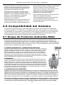
A. PUNTO DE ANCLAJE / CONECTOR DE ANCLAJE
El primer componente es el punto de anclaje / conector de anclaje. El punto de
anclaje, también conocido como punto de amarre, es un punto seguro utilizado
SDUD¿MDUORVGLVSRVLWLYRVGHFRQH[LyQ\GHEHVHUFDSD]UHVLVWLUOE
kN) por trabajador o cumplir con los requisitos de la norma OSHA 1926.502
para un factor de seguridad de dos, como los de una viga “I” u otra estructura
de soporte. A veces se requieren conectores de anclaje, por ejemplo, correas
para travesaños y pernos de argolla, para que las conexiones sean compatibles
entre el dispositivo de conexión y el punto de anclaje.
A
B
B. APAREJO
El segundo componente del sistema es el equipo de protección personal que traen
puesto los trabajadores mientras realizan su labor. Miller Fall Protection fabrica arneses de cuerpo entero, cinturones de posicionamiento y cinturones para entornos de
WUDEDMRHVSHFt¿FRV/RVDUQHVHVGHFXHUSRHQWHURHVWiQGLVHxDGRVSDUDFRQWULEXLUD
la parada de una caída libre y se deben usar siempre que el trabajador esté expuesto
a una posible caída libre. Para reducir al mínimo las fuerzas de la caída, el arnés de
cuerpo entero se debe usar conjuntamente con un equipo amortiguador de impacto.
Es imperativo usar el arnés como es debido.
C. DISPOSITIVO DE CONEXIÓN
El último componente del sistema es el dispositivo de conexión. La característica más importante del
dispositivo de conexión es el amortiguador de impacto incorporado. Independientemente de que dicho
dispositivo sea una cuerda de seguridad con amortiguador de impacto o una cuerda salvavidas retráctil,
ambas están diseñadas para reducir de manera impresionante las fuerzas ejercidas para detener la
FDtGD/DVFXHUGDVGHVHJXULGDGGH¿EUDWHMLGDVRGHDODPEUHXVDGDVSDUDODGHWHQFLyQGHFDtGDV'(BEN usarse conjuntamente con un amortiguador de impacto (por ejemplo, el paquete Miller SofStop).
De manera individual, ninguno de estos componentes ofrece protección contra una caída. Usados en conjunto como es debido, conforman el “sistema Miller” y se convierten
en una parte de vital importancia del “sistema completo de protección contra caídas”.
28
C
Instrucciones Para El Usuario - Español
3.0 Instalación de los Conectores de Anclaje
Advertencias, limitaciones y requisitos de instalación
referentes a todos los conectores de anclaje
$QWHVGHLQVWDODUFXDOTXLHUFRQHFWRUGHDQFODMHLQVSHFFLyQHORFXLGDGRVDPHQWHSDUD
DVHJXUDUVHGHTXHVHHQFXHQWUHHQFRQGLFLRQHVGHVHUXVDGR9HUL¿TXHTXHQRKD\D
SLH]DVIDOWDQWHVRGHWHULRUDGDV1RXVHHVWHHTXLSRVLFXDOTXLHUFRPSRQHQWHQRIXQFLRQD
FRUUHFWDPHQWHRODXQLGDGSDUHFHHVWDUGDxDGDGHFXDOTXLHUIRUPD&RQVXOWHODVHFFLyQ
sobre inspección de este manual.
6yORSHUVRQDOHQWUHQDGR\FRPSHWHQWHGHEHLQVWDODU\XWLOL]DUHVWHHTXLSR
$VHJ~UHVHGHTXHODDOWXUDGHOSXQWRGHDQFODMHOLPLWHODGLVWDQFLDGHFDtGDOLEUHDP
SLHVRPHQRV
6LHPSUHWUDEDMHGLUHFWDPHQWHEDMRHOSXQWRGHDQFODMHSDUDHYLWDUXQDOHVLyQSRUFDtGD
columpiada.
$VHJ~UHVHGHTXHHOFRQHFWRUGHDQFODMHVHHQFXHQWUHDXQDDOWXUDWDOTXHHQFDVRGH
XQDFDtGDQRKDJDLPSDFWRHQXQQLYHOLQIHULRU$OVHOHFFLRQDUXQSXQWRGHDQFODMH
VLHPSUHUHFXHUGHTXHORVDPRUWLJXDGRUHVGHLPSDFWRVHHVWLUDQDOVHUVRPHWLGRVDODV
IXHU]DVGHGHWHQFLyQGHFDtGD&RQVXOWHODVHWLTXHWDVHLQVWUXFFLRQHVVXPLQLVWUDGDVFRQ
el dispositivo de conexión para obtener la distancia máxima de estiramiento.
/RVVLVWHPDVSDUDGHWHQFLyQGHFDtGDVXWLOL]DGRVFRQHOFRQHFWRUGHDQFODMHGHEHQ
HTXLSDUVHGHFRQIRUPLGDGFRQORVUHTXLVLWRVHVWDEOHFLGRV>(VSUHFLVROHHUFRPSUHQGHU
y seguir las instrucciones y advertencias suministradas con el sistema personal para
GHWHQFLyQGHFDtGDV@
$VHJ~UHVHGHTXHWRGDVODVFRQH[LRQHVGHOVLVWHPDSDUDGHWHQFLyQGHFDtGDVVHDQ
compatibles.
(OFRQHFWRUGHDQFODMHGHEHVHUFRPSDWLEOHFRQHOJDQFKRGHUHVRUWHRFRQHOPRVTXHWyQ
GHOGLVSRVLWLYRGHFRQH[LyQ\QRGHEHDSOLFDUQLQJXQDFDUJDHQHOUHWpQROLQJXHWH
6yORXWLOLFHPRVTXHWRQHVDVHJXUDGRUHVJDQFKRVDVHJXUDGRUHVGHUHVRUWHXRWURV
FRQHFWRUHVRGLVSRVLWLYRVGHFRQH[LyQDSUREDGRVSRU0LOOHUSDUDXQLUORVDHVWHHTXLSR
-DPiVXVHXQFRQHFWRUGHDQFODMHTXHLPSLGDHOFLHUUHGHOJDQFKRGHUHVRUWHRGHOUHWpQR
OLQJXHWHGHOPRVTXHWyQ
(OFRQHFWRUGHDQFODMHHV62/$0(17(3$5$81$3(5621$
7RGRVORVFRQHFWRUHVGHDQFODMHLQFOXLGRVHQHVWHPDQXDOWLHQHQN1OEGH
UHVLVWHQFLDPtQLPDDODWUDFFLyQ
/DHVWUXFWXUDDODTXHVH¿MHHVWHSURGXFWRGHEHVHUFDSD]GHVRSRUWDUN1OE
GHFDUJDGHWUDFFLyQXRIUHFHUXQIDFWRUGHVHJXULGDGGHHQODGLUHFFLyQGHOWLUyQ
/RVUHTXLVLWRVSDUDHODQFODMHEDVDGRVHQODVQRUPDV$16,VRQFRPRVLJXH
Para los sistemas de detención de caídas, los anclajes deben poder soportar una carga estática de 5,000 lb (22.2 kN) en
HOFDVRDQFODMHVQRFHUWL¿FDGRVRGRVYHFHVODIXHU]DGHGHWHQFLyQPi[LPDHQHOFDVRGHDQFODMHVFHUWL¿FDGRV
3DUDORVVLVWHPDVGHGHWHQFLyQGHSRVLFLRQDPLHQWRORVDQFODMHVGHEHQSRGHUVRSRUWDUXQDFDUJDHVWiWLFDGHOE
N1HQHOFDVRDQFODMHVQRFHUWL¿FDGRVRGRVYHFHVODIXHU]DSUHYLVLEOHHQHOFDVRGHDQFODMHVFHUWL¿FDGRV
3DUDOLPLWDFLyQGHGHVSOD]DPLHQWRORVDQFODMHVGHEHQSRGHUVRSRUWDUXQDFDUJDHVWiWLFDGHOEN1HQHOFDVR
DQFODMHVQRFHUWL¿FDGRVRGRVYHFHVODIXHU]DSUHYLVLEOHHQHOFDVRGHDQFODMHVFHUWL¿FDGRV
3DUDORVVLVWHPDVGHUHVFDWHORVDQFODMHVGHEHQSRGHUVRSRUWDUXQDFDUJDHVWiWLFDGHOEN1HQHOFDVR
DQFODMHVQRFHUWL¿FDGRVRFLQFRYHFHVODFDUJDDSOLFDGDHQHOFDVRGHDQFODMHVFHUWL¿FDGRV
&XDQGRVHVXMHWDPiVGHXQVLVWHPDSHUVRQDOGHGHWHQFLyQGHFDtGDVDXQDQFODMHVHGHEHQPXOWLSOLFDUODVIXHU]DVGH
anclaje indicadas arriba por el número de sistemas sujetados a dicho anclaje.
/DDUJROOD³'´PRQWDGDODVDQFODV³'´GHSHUQR\\HODQFOD
³'´GHSHUQRSDUDFRQFUHWR&FXPSOHQODVQRUPDVGH26+$\$16,$=
>NJOE@
>Nota: Si el sistema es utilizado por un trabajador con un peso total (cuerpo y herramientas) entre 140.6
NJOE\NJOEHQWRQFHVHOHPSOHDGRUGHEHPRGL¿FDUFRPRFRUUHVSRQGDORVFULWHULRV\
SURWRFRORVD¿QGHSURSRUFLRQDUODGHELGDSURWHFFLyQSDUDWDOHVSHVRVPiVSHVDGRVRHOVLVWHPDQRVH
FRQVLGHUDUiHVWDUHQFXPSOLPLHQWRGHORVUHTXLVLWRVGHODQRUPD26+$G@
29
Instrucciones Para El Usuario - Español
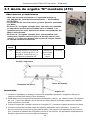
3.1 Ancla de argolla “D” montada (410)
Advertencias y Limitaciones
81$VRODSHUVRQD~QLFDPHQWH/DFDSDFLGDGPi[LPDHV
NJOELQFOXLGDVODVKHUUDPLHQWDV²12(;&('$
(67(3(62
&RQHVWDVDQFODVXVHVyORSHUQRV\SLH]DV¿MDGRUDVDSUREDGRV
por Miller.
(O$QFOD³'´GHDUJROODPRQWDGDVyORGHEHVHULQVWDODGD
HQVXSHU¿FLHVKRUL]RQWDOHVHOHYDGDVVREUHODFDEH]D/DV
instalaciones para otras aplicaciones deben ser aprobadas por
Miller Fall Protection.
(O$QFOD³'´GHDUJROODPRQWDGDHVWiDSUREDGDVRODmente para utilizarse como conector de anclaje para un solo
usuario, y no debe ser utilizada como parte de ningún sistema
de cuerda salvavidas horizontal.
Núm. de
modelo
410
Descripción
Ancla de argolla “D” con placa de
montaje, 4 pernos de 3/8” x 3-1/2”
de grado 5, 4 tuercas de 3/8” y 4
arandelas de seguridad de 3/8”
Material
Peso
Aleación de
acero forjado
por estampación
1 lb. 9.6 oz.
Anclaje / estructura
Placa de montaje
(QVDPEOHGHOSHUQR
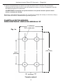
Instalación
$UJROOD³'´
/RFDOLFHHLGHQWL¿TXHXQDQFODMHRHVWUXFWXUDFRPSDWLEOHDSUREDGR$VHJ~UHVHGHTXHHO
lugar de montaje esté limpio y libre de basura.
*XLiQGRVHFRQXQDFRSLDGHODSODQWLOODVXPLQLVWUDGDYHD¿JDWDODGUHFXDWURDJXMHURV
GH´PPGHGLiPHWURHQODHVWUXFWXUD'HEHGHMDUVHVX¿FLHQWHHVSDFLRSDUDDSUHWDU
todos los pernos y tuercas.
3. Coloque la placa de montaje a través de la argolla “D”, centrando la barra de ésta en la placa.
4. Coloque la placa de montaje sobre los agujeros taladrados en la estructura. Coloque un
perno a través de uno de los agujeros de la placa y del agujero correspondiente de la estructura. Coloque la arandela de seguridad y la tuerca en el perno, sin apretarlos completamente.
Repita la operación con los tres pernos restantes.
30
Instrucciones Para El Usuario - Español
$SULHWHFRPSOHWDPHQWHORVSHUQRVDXQSDUGHWRUVLyQGHD1PDOESLH
$VHJ~UHVHGHTXHWRGDODWXHUFDHVWpHQURVFDGDHQHOSHUQR\GHTXHHOGLVSRVLWLYRHVWp¿MR
de manera segura en la estructura.
ADVERTENCIA: No aplique un apriete excesivo. Un apriete excesivo puede causar
daños al sistema de anclaje.
5HPRFLyQ3DUDGHVPRQWDUODDUJROOD³'´\ODSODFDGHPRQWDMHGHODQFODMHRHVWUXFWXUDDÀRMH\
retire todas las tuercas, arandelas de seguridad y pernos.
PLANTILLA DE TALADRADO
PARA MONTAR EL ANCLA DE ARGOLLA “D”
PP
Fig. 1a
´PPGLD
PP
´
PP
´
PP
7DPDxRQDWXUDO
31
Instrucciones Para El Usuario - Español
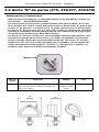
3.2 Ancla “D” de perno (415, 416/417, 418/419)
Advertencias y Limitaciones
81$VRODSHUVRQD~QLFDPHQWH/DFDSDFLGDGPi[LPDHVNJOELQFOXLGDVODV
KHUUDPLHQWDV²12(;&('$(67(3(62
&RQHVWDVDQFODVXVHVyORSHUQRV\SLH]DV¿MDGRUDVDSUREDGRVSRU0LOOHU(QHOFDVR
GHORVPRGHORV\HOXVXDULRGHEHSURSRUFLRQDUXQSHUQRGH´GHJUDGRSDUD
HODQFOD³'´GHSHUQRRXQSHUQRGH´GHJUDGRSDUDHODQFOD³'´GHSHUQR
/DV$QFODV³'´GHSHUQR\SXHGHQVHULQVWDODGDVHQVXSHU¿FLHV
YHUWLFDOHVXKRUL]RQWDOHVHOHYDGDVVREUHODFDEH]D/DVLQVWDODFLRQHVSDUDRWUDVDSOLFDciones deben ser aprobadas por Miller Fall Protection.
/DV$QFODV³'´GHSHUQRPRGHORHVWiQDSUREDGDVVRODPHQWHSDUDXWLOL]DUVHFRPR
conectores de anclaje para un solo usuario, y no deben ser utilizadas como anclajes
¿QDOHVHQQLQJ~QVLVWHPDGHFXHUGDVDOYDYLGDVKRUL]RQWDO/DV$QFODV³'´GHSHUQR
PRGHORV\HVWiQDSUREDGDVSDUDVHUXWLOL]DGDVFRQORV6LVWHPDVGH
FXHUGDVDOYDYLGDVKRUL]RQWDO6N\*ULS7HFK/LQH\7LWDQ:HE/LQHGH0LOOHU&XDOHVTXLHUDRWUDVDSOLFDFLRQHVGHEHQVHUDSUREDGDVSRU0LOOHU
Modelo 415
Núm. de
modelo
415
Descripción
Ancla “D” de perno de una pieza con arandela de
seg. y tuerca; perno de 13 mm (1/2”) de diám.; 32
mm (1-1/4”) de long
´
PP
´
PP
(WLTXHWDGHDGYHUWHQFLD
´
PP
32
Material
Peso
Aleación de acero
forjado por estampación
12.8 oz
Instrucciones Para El Usuario - Español
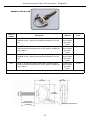
Modelos 416 & 418
Núm. de
modelo
Descripción
Material
Peso
416
Ancla “D” de perno con piezas varias (perno de 5/8” grado 8,
arandela de seg. y tuerca); para espesores hasta de 101.6 mm
(4”)
Aleación de
acero forjado
por estampación
1 lb. 8 oz.
417*
Ancla “D” de perno sin piezas varias (Nota: El usuario proporciona las piezas de montaje: perno de 5/8“ grado 8, arandela de
seg. y tuerca.)
Aleación de
acero forjado
por estampación
14.7 oz.
418
Ancla “D” de perno con piezas varias (perno de 3/4” grado 8,
arandela de seg. y tuerca); para espesores hasta de 101.6 mm
(4”)
Aleación de
acero forjado
por estampación
1 lb. 8 oz.
419*
Ancla “D” de perno sin piezas varias (Nota: El usuario proporciona las piezas de montaje: perno de 3/4“ grado 8, arandela de
seg. y tuerca.)
Aleación de
acero forjado
por estampación
14.7 oz.
*La longitud del perno puede variar para dar acomodo a varios espesores.
´
PP
´
PP
´
PP
(VSHVRUGH
WUDEDMRKDVWDGH
PP
(WLTXHWDGHDGYHUWHQFLD
33
Instrucciones Para El Usuario - Español
Instalación
$QFOD³'´GH
perno
$QFOD³'´GH
perno
/RFDOLFHHLGHQWL¿TXHXQDQFODMHRHVWUXFWXUDFRPSDWLEOHDSUREDGR$VHJ~UHVHGHTXHHO
lugar de montaje esté limpio y libre de basura.
2. Localice o taladre un agujero de tamaño adecuado según la tabla mostrada abajo. Debe
GHMDUVHVX¿FLHQWHHVSDFLRSDUDFRORFDUODDUDQGHODGHVHJXULGDG\DSUHWDUODWXHUFD
7DPDxRGHODJXMHUR
Modelo
415
14 mm (17/32”) de diám.
416/417
17 mm (21/32”) de diám.
418/419
20 mm (25/32”) de diám.
ADVERTENCIA: En el caso de anclas “D” de perno instaladas en vigas “W”, el agujero de
PRQWDMHGHEHWDODGUDUVHSHUSHQGLFXODUPHQWHDODODGHODYLJDYHU¿JD(QHOFDVRGH
anclas “D” de perno que van a instalarse en vigas de forma “S”, los agujeros deben taladrarse perpendicularmente al ala de la viga y debe usarse una arandela rebajada (es decir,
FRQELVHOFKDÀiQRHQIRUPDGHFXxDSDUDDVHJXUDUVHGHTXHHOSHUQRGHODQFOD³'´\ROD
WXHUFD\ODDUDQGHODDVLHQWHQDHVFXDGUDFRQWUDODVXSHU¿FLHGHODYLJDYHU¿JE
Fig. 2a
)RUPD³:´DODDQFKD
Fig. 2b
)RUPD³6´YLJD³,´HVWUXFWXUDO
Arandela rebajada
$QFOD³'´GH
$QFOD³'´GHSHUQR
3. 0RQWDMHGHODQFOD³'´GHSHUQR
Para montar el ancla "D" de perno 415 introduzca el tallo del perno a través del agujero de la
estructura. Coloque la arandela de seguridad y la tuerca.
0RQWDMHGHODQFOD³'´GHSHUQR
Para montar el ancla “D” de perno 416/417 pase un perno aprobado de 5/8” de grado 8 por el
agujero del conector y por el agujero de la estructura. Coloque la arandela de seguridad y la
tuerca.
0RQWDMHGHODQFOD³'´GHSHUQR
Para montar el ancla “D” de perno 418/419 pase un perno aprobado de 3/4” de grado 8 por el
agujero del conector y por el agujero de la estructura. Coloque la arandela de seguridad y la
tuerca.
34
Instrucciones Para El Usuario - Español
4. Apriete el perno completamente al par de torsión recomendado según la tabla mostrada
abajo. Asegúrese de que toda la tuerca esté enroscada en el perno y de que el dispositivo
HVWp¿MRGHPDQHUDVHJXUDHQODHVWUXFWXUD
Modelo
9DORUHVGHWRUTXH
415
45-55 ft. lbs.
416/417
125 ft. lbs.
418/419
185-195 ft. lbs.
ADVERTENCIA: No aplique un apriete excesivo. Un apriete excesivo puede causar
daños al sistema de anclaje.
5HPRFLyQ$ÀRMH\UHWLUHODWXHUFD\ODDUDQGHOD'HVSXpVUHWLUHHODQFOD'GHSHUQRGHO
anclaje o estructura.
35
Instrucciones Para El Usuario - Español
3.3 Ancla “D” de perno (417C)
Advertencias y Limitaciones
81$VRODSHUVRQD~QLFDPHQWH/DFDSDFLGDGPi[LPDHVNJOELQFOXLGDVODV
KHUUDPLHQWDV²12(;&('$(67(3(62
&RQHVWDVDQFODVXVHVyORSHUQRV\SLH]DV¿MDGRUDVDSUREDGRVSRU0LOOHU
(ODQFOD³'´GHSHUQRSDUDFRQFUHWR0LOOHU&VyORGHEHVHULQVWDODGDHQFRQFUHWR
FRPSOHWDPHQWHIUDJXDGRGHSHVRQRUPDOFRQXQDUHVLVWHQFLDDODFRPSUHVLyQGH
03DSVL
(O$QFOD³'´GHSHUQRSDUDFRQFUHWRPRGHOR&SXHGHVHULQVWDODGDHQVXSHU¿FLHV
YHUWLFDOHVRHOHYDGDVKRUL]RQWDOHVVREUHODFDEH]D/DVLQVWDODFLRQHVSDUDRWUDVDSOLFDciones deben ser aprobadas por Miller Fall Protection.
$QWHVGHXWLOL]DUHO$QFOD³'´&GHSHUQRSDUDFRQFUHWRHQFXDOTXLHUDSOLFDFLyQGH
cuerda salvavidas horizontal, siempre contacte a Miller Fall Protection para obtener su
aprobación.
Núm. de
modelo
Descripción
Material
Peso
417C
Ancla “D” de perno con perno de expansión
para concreto (16 mm x 152 mm (5/8” x 6”)
con arandela de seguridad de 16 mm (5/8”))
Aleación de acero forjado
por estampación
1 lb. 4 oz.
Instalación
Al considerar el lugar de instalación, asegúrese de que haya como mínimo 228 mm (9”) desde
WRGRVORVERUGHV\XQLRQHVGHFRQWUROYHU¿JD
ADVERTENCIA: No instale el ancla “D” de perno para concreto a menos de 228
mm (9”) de los bordes, ni la instale en concreto que esté rajado, dañado, roto
o deteriorado.
1. Con un taladro percutor taladre un agujero de 117.5 mm (4-5/8”) como mínimo de profundiGDGGHLQFUXVWDFLyQYHU¿JE
(OLPLQHWRGRHOHVFRPEURGHODJXMHURFRQXQDSHUDVRSODGRUDYHU¿JF
3. Para proteger la rosca del perno durante la instalación coloque la tuerca en el perno de
H[SDQVLyQ/XHJRDWRUQLOOHHOSHUQRHQHORUL¿FLRKDVWDTXHTXHGHQVREUHODVXSHU¿FLHGH
GHSXOJDGDPPDGHSXOJDGDPPGHOWRUQLOORYHU¿JG
4. Retire la tuerca y coloque el ancla “D” en el perno. Después coloque la arandela plana y en
seguida la arandela de seguridad y la tuerca. NOTA: Después del montaje deben sobresalir
YXHOWDVGHODURVFDSRUORPHQRV$SOLTXHXQSDUGHWRUVLyQGHD1PD
OESLHYHU¿JH
ADVERTENCIA: No aplique un apriete excesivo. Un apriete excesivo puede causar
daños al sistema de anclaje.
Remoción: Si la instalación se realizó en un agujero sin fondo, después de usarse el ancla “D”
SXHGHUHWLUDUVH\HOSHUQRSXHGHLQWURGXFLUVHKDVWDGHMDUORDUDVFRQODVXSHU¿FLH
36
Instrucciones Para El Usuario - Español
Perno de expansión
Fig. 3a
Profundidad de incrustación
Borde
Borde
PP´PtQLPR
PP´PtQLPR
Fig. 3c
Fig. 3b
Fig. 3d
Fig. 3e
PP
to
PP
37
Instrucciones Para El Usuario - Español
4.0 Inspección y Mantenimiento
Inspección
Los conectores de anclaje Miller están fabricadas para los rudos ambientes de trabajo de
hoy en día. Para mantener su vida útil y gran desempeño, todos los componentes deben
inspeccionarse con frecuencia. /RVFRQHFWRUHVGHDQFODMHGHEHQVHULQVSHFFLRQDGRV
visualmente por el usuario antes de cada uso y deben ser inspeccionados
periódicamente por una persona competente.
Inspeccione el producto para ver si tiene cualquiera de los siguientes defectos: está doblado,
agrietado, distorsionado, desgastado, funciona mal o tiene partes dañadas; deformación; corrosión;
elementos de unión sueltos o partes o componentes faltantes; deterioro; señales de que el producto
ha sido sujeto a una detención de caída; o cualquier otra indicación de daños o problemas que
puedan afectar la integridad y desempeño del producto. Si tiene dudas comuníquese con el
fabricante.
Los dispositivos que no pasen la inspección o hayan sido sometidos
a fuerzas de detención de caída deben retirarse del servicio.
Limpieza y Almacenamiento
Con un cuidado básico de todo el equipo Miller Fall Protection se prolonga la vida de servicio de
la unidad y se contribuye al correcto desempeño de su vital función de seguridad. Limpie periódicamente el producto para eliminar toda suciedad, pintura, corrosivos, contaminantes y otros
materiales que puedan haberse acumulado. Cuando no se tenga en uso, guarde el producto en
un área limpia, seca y carente de exposición a emanaciones y agentes corrosivos.
Servicio
Las reparaciones deben ser efectuadas exclusivamente por el fabricante del equipo o bien por
personas o entidades autorizadas por escrito por el fabricante. Debe llevarse un registro con todas las fechas de servicio e inspecciones realizados al dispositivo. Sólo las piezas de repuesto
originales de Miller se aprueban para ser usadas en este dispositivo. Aquellos dispositivos no
reparables que no pasen la inspección deben desecharse de tal manera que se prevenga su
posterior uso por accidente. Si tiene preguntas comuníquese con el Depto. de Servicios Técnicos de Miller, llamando al 1-800-873-5242.
38
U s e r In s tru c ti o n s - E n g l i s h
Product Labels
Étiquettes de Produit
Etiquetas del Producto
:$51,1*
:$51,1*
$OO SHUVRQV XVLQJ WKLV HTXLSPHQW PXVW
UHDG XQGHUVWDQG DQG IROORZ DOO
LQVWUXFWLRQV )DLOXUH WR GR VR PD\
UHVXOW LQ VHULRXV LQMXU\ RU GHDWK
$OO SHUVRQV XVLQJ WKLV HTXLSPHQW PXVW
UHDG XQGHUVWDQG DQG IROORZ DOO
LQVWUXFWLRQV )DLOXUH WR GR VR PD\
UHVXOW LQ VHULRXV LQMXU\ RU GHDWK
/%5(9&
/%5(9&
39
Inspection and Maintenance Log
Registre D'inspection et D'entretien
Registro de Inspección y Mantenimiento
'$7(2)0$18)$&785(_________________________________________________
'$7('()$%5,&$7,21)(&+$'()$%5,&$&,Ï1
02'(/180%(5________________________________________________________
180e52'(02'Ê/(1Ò0'(02'(/2
'$7(385&+$6('______________________________________________________
'$7('¶$&+$7)(&+$'(&2035$
,163(&7,21'$7(
'$7('¶,163(&7,21
)(&+$'(,163(&&,Ï1
,163(&7,21
,7(06127('
&255(&7,9(
$&7,21
P2,176127e6
/256'(/¶,163(&7,21
P81726'(,163(&&,Ï1
5(/(9$17(6
A&7,21&255(&7,9(
M(','$&255(&7,9$
Approved by:
Approuvé par:
Aprobado por:
Approved by:
Approuvé par:
Aprobado por:
Approved by:
Approuvé par:
Aprobado por:
Approved by:
Approuvé par:
Aprobado por:
Approved by:
Approuvé par:
Aprobado por:
Approved by:
Approuvé par:
Aprobado por:
Approved by:
Approuvé par:
Aprobado por:
Approved by:
Approuvé par:
Aprobado por:
Approved by:
Approuvé par:
Aprobado por:
Approved by:
Approuvé par:
Aprobado por:
40
0$,17(1$1&(
3(5)250('
(175(7,(1())(&78e
M$17(1,0,(172
5($/,=$'2
0,//(5®)$//3527(&7,21352'8&76
727$/6$7,6)$&7,21$6685$1&(
At Miller Fall Protection, we have been providing quality Miller brand fall protection
equipment to millions of workers worldwide since 1945.
/,0,7('/,)(7,0(:$55$17<
%$&.('%<29(5<($56,17+()$//3527(&7,21%86,1(66
We sincerely believe that our fall protection equipment is the best in the world.
Our products endure rigorous tests to ensure that the fall protection equipment you trust is manufactured
to the highest standards. Miller fall protection products are tested to withstand normal wear and tear,
but are not indestructible and can be damaged by misuse.
Our Limited Lifetime Warranty does not apply to normal wear and tear or abusive treatment of the product.
In the unlikely event that you should discover defects in either workmanship or materials,
under our Limited Lifetime Warranty, we will repair or replace the product at our expense.
If a replacement is necessary and your product is no longer available, a comparable product will be substituted.
Should a product issue surface, contact us at 800.873.5242.
0DQXIDFWXULQJVSHFL¿FDWLRQVDUHVXEMHFWWRFKDQJHZLWKRXWQRWLFH
352'8,760,//(5®)$//3527(&7,21
$6685$1&('(6$7,6)$&7,21727$/(
Chez Miller Fall Protection, nous fournissons des équipements de protection contre les chutes de marque
Miller de qualité à des millions de travailleurs dans le monde entier depuis 1945.
*$5$17,(/,0,7e(¬9,(
$6685e(*5Æ&(¬3/86'($163$66e6'$16/('20$,1('(/$3527(&7,21&2175(/(6&+87(6
Nous croyons sincèrement que notre équipement de protection contre les chutes est le meilleur au monde. Nos
SURGXLWVVRQWVRXPLVjGHVWHVWVULJRXUHX[D¿QG¶DVVXUHUTXHOHVpTXLSHPHQWVGHSURWHFWLRQFRQWUH
OHVFKXWHVGDQVOHVTXHOVYRXVDYH]FRQ¿DQFHVRQWIDEULTXpVVHORQOHVQRUPHVOHVSOXVH[LJHDQWHV
/HVSURGXLWVGHSURWHFWLRQFRQWUHOHVFKXWHV0LOOHUVRQWVRXPLVjGHVHVVDLVSRXUYpUL¿HUTX¶LOVUpVLVWHQWjXQHXVXUH
normale; ils ne sont cependant pas indestructibles et peuvent s’endommager en cas de mauvaise utilisation. Notre
garantie limitée à vie ne s’applique pas à l’usure normale ou à un usage abusif du produit.
Dans le cas peu probable où vous découvririez des défauts, soit de fabrication, soit de matériau,
dans le cadre de notre garantie à vie, nous réparerons ou remplacerons le produit à nos frais.
En cas de remplacement, si votre produit n’est plus offert, vous recevrez un produit comparable.
En cas de problème sur un produit, nous contacter au 800-873-5242.
/HVFDUDFWpULVWLTXHVGHIDEULFDWLRQSHXYHQWrWUHPRGL¿pHVVDQVSUpDYLV
352'8&726$17,&$Ë'$60,//(5®
*$5$17Ë$'(6$7,6)$&&,Ï1727$/
En Miller Fall Protection, venimos suministrando desde 1945 los equipos de protección anticaídas
con la calidad Miller a millones de trabajadores en todo el mundo.
*$5$17Ë$/,0,7$'$'(3259,'$
1265(63$/'$10È6'($f26(1/$)$%5,&$&,Ï1'((48,32$17,&$Ë'$6
Sinceramente creemos que su equipo de protección contra caídas es el mejor del mundo. Nuestros productos resisten
rigurosas pruebas para garantizar que el equipo de protección contra caídas en el que usted confía está fabricado de
conformidad con las normas más elevadas. Los productos anticaídas Miller son sometidos a pruebas para que resistan el
desgaste normal, pero no son indestructibles y su incorrecta utilización puede dañarlos.
Nuestra Garantía limitada de por vida no se aplica al desgaste normal ni al maltrato del producto.
En el poco probable caso de que usted descubriera defectos de mano de obra o materiales, por nuestra Garantía limitada de por vida, repararemos o sustituiremos el producto por cuenta nuestra. Si un reemplazo es necesario y nuestro
producto ya no está disponible, se lo sustituiremos por otro comparable.
En caso de que surja un problema con el producto, contáctenos al 800.873.5242.
/DVHVSHFL¿FDFLRQHVGHIDEULFDFLyQHVWiQVXMHWDVDPRGL¿FDFLRQHVVLQSUHYLRDYLVR
41
Toll Free: 800.873.5242
Fax: 800.892.4078
Download this manual at: www.millerfallprotection.com
Téléchargez ce manuel à l’adresse: www.millerfallprotection.com
Puede bajar por Internet este manual en: www.millerfallprotection.com
Sperian Fall Protection, Inc.
P.O. Box 271, 1345 15th Street
Franklin, PA 16323 USA