1
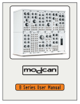
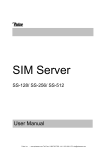
MIDImplant
micro MIDI-2-CV device
USER MANUAL
Roman Sowa 2011
www.midimplant.com
1.
Overview
Thank you for choosing MIDImplant as your new MIDI2CV converter. This short manual will guide you
through installation, and available settings.
The board was designed to be mounted directly at the DIN5 socket pins, but can also be installed
anywhere inside your instrument if that's more feasible. No mounting holes are provided. The strength
of connecting vires is enough to secure it in place, as it weighs barely 2 grams.
It has 2 groups of analog outputs, suitable to control analog synths with V/oct or Hz/V scaling.
MIDImplant comes factory set to 1V/oct scale. CV1 responds to MIDI keyboard on channel 1 and "C"
lowest key. CV2 is velocity output. Each CV can be reassigned to different type of MIDI event, not only
keyboard notes - this is described in chapter 5.
The board requires only single power supply, and all settings are done with use of one SPST button - it's
not part of the delivery, any normally open switch will work. More settings are accessible via MIDI
System-Exclusive commands.
MIDI System-Exclusive is available in boards with firmware version 2.5 and higher. The version number
is indicated as 2 first digits of serial number.
MIDImplant board described here is a product of:
"MIDI-hardware" Roman Sowa, ul. Azotowa 15B, 41-503 Chorzów, Poland
phone +48 32 7633 931, email [email protected]
© 2011, Roman Sowa
made in Poland, EU
2.
Layout
Pictures below show how to locate the soldering pads in MIDImplant board, and depicts their role. They
are:
2 Control Voltage outputs
●
2 Gate outputs
●
power supply input
●
ground
●
setup (EDIT) button input
●
group of pads for connecting MIDIIN DIN5 socket
Power supply
GND
+6..15V
CV2
CV1
gate2
gate1
The EDIT button should be connected to
the pad indicated in the picture, with 2nd
lead connected to ground. You don't need
to connect it at all if SysEx will be used or
if default setting is OK: channel 1, starting
note C (MIDI #36), 1V/oct, velocity on
CV2.
EDIT
input
MIDI IN on
bottom side
●
MIDI IN:
DIN-5
DIN-4
The board has no holes for mounting
screws. Instead it can be soldered directly to DIN5 socket. Synthesizers usually have enough space
behind back panel to fit it inside. Total length from MIDI socket face to the back of the board is less than
2'' / 5cm. MIDI IN signal should be connected to pads on the bottom, marked above as DIN-4 and DIN5. If the board will be mounted directly on DIN socket pins, you should solder the board to unconnected
rectangle pads on the top side.
This is enough for securing it in place. Then use short pieces of wire to solder DIN contacts 4 and 5 to
rectangle pads at the bottom. This is shown in drawing below. Middle pin of DIN socket, number "2",
must not be connected anywhere, it must be left open to comply with MIDI specification.
Before you start to solder the socket to MIDImplant, insert a MIDI plug into the socket, to
align contacts in their positions. They are loose inside so the
plug can be easier inserted. If you solder the socket without a plug
inside, the contacts will not be perfectly aligned and plugging the
MIDI cable will bend the contacts every time you plug it. This, in
time, may cause the board to crack and loose connection with the
socket.
3.
Power supply
First connect the ground input, as shown in layout diagram. The ground input should be connected with
reasonably thick wire to star-ground point, usually located at the power supply. The quality of ground
connection directly affects the quality of generated Control Voltage. It's the reference point of CV outs. It
can also be taken from the ground reference point of your VCO.
MIDImplant is designed to work with typical supply voltages present in any electronic instrument. It
requires only one positive supply line, and voltage range from +6V up to +15V. Current drawn is less
than 10mA. It can be taken from any place inside the synth, as long as it does not exceed 15V. Power
input must be DC. Connecting AC power, or reversing the power leads will immediately
damage the board.
4.
CV/gate outputs
MIDImplant has 2 sets of outputs. Control voltage and gate pads are located at the edge of PCB. CV
outputs have impedance of 100 ohms and should be connected to a resistance greater than 10k,
otherwise it may be impossible to achieve full range of 5V and maintain precision. Usually CV inputs
have 100k impedance, so it's perfectly OK. Gate outputs use transistor buffer with pull-up resistor. Gateon is represented with the same voltage as power supply (6..15V).
4.1. CV outputs
Each CV output can be configured to respond to one MIDI event. Both outputs are independent to some
extent. The only case when they work in conjunction is CV1 configured as MIDI notes. CV2 then
becomes Velocity output for the notes played by CV1. It is possible then to change CV2 to something
else, but CV2 always becomes velocity right after programming CV1 as MIDI notes.
All available MIDI events represented in Control Voltage are listed below:
●
Note on/off
●
Note velocity - possible only in CV2
●
Pitch Bend
●
Continuous Controller
●
Program Change
●
Channel After Touch
●
Polyphonic After Touch
Control Voltage varies from 0V up to 5V. It makes 61-note range for 1V/oct scale. If CV is configured as
MIDI event different than notes, 0V represents lowest MIDI value, and 5V is output when highest MIDI
value is received.
All controllers are represented in voltage as one of 128 levels, except Pitch Bend, working with full 14bit resolution (16384 steps). Neutral position of PitchBender gives 2.5V on MIDImplant output. Note
on/off can output 61 levels of voltage at most.
For note on/off, CV scale can be adjusted in a wide range, from 0.44V/oct to over 2V/oct if using
settings button, and much wider via SysEx. When configured in Hz/V scale, the voltage reaches 5V at
the top note. This is described in chapter about tuning (5.3-5.4). If the scale is higher than 1V/oct,
there is, of course, no room for 61 keys in 5V range, so it is limited to lower number of keys. Every note
higher than this limit gives 5V at CV output.
4.2. Gate outputs
Each Gate output associated with CV output generates voltage indicating the duration of MIDI note.
When MIDImplant is configured to respond to MIDI notes, gate output remains at nearly 0V until any
note is played. It then goes up to the supply voltage level, and stays there until all notes are released. It
is typical V-trigger mode.
This is only true when CV output is configured for MIDI notes. In all other cases gate output remains at
nearly 0V.
5.
User settings with EDIT button
After successful installation, you can set up the MIDI events associated with each CV output. To do so,
your synth must be powered on, and have EDIT button connected (see the layout). There are only 4
parameters to set:
1. channel and MIDI event for CV1/gate1
2. channel and MIDI event for CV2/gate2
3. Keyboard scale select (common for both CV)
4. V/oct fine tuning (common for both CV)
To select which parameter you want to edit, press the setup button appropriate number of times. Press
once for setting CV1, twice for CV2, 3 times for scale select or 4 times to fine tune the scale. There's no
time limit for pressing the EDIT button several times. But don't push it too fast, because it may be
treated as contact bounce, and ignored.
All user settings are memorized in nonvolatile memory, taking power off does not reset anything to
defaults, the settings are kept as they were last entered.
5.1. Channel and event of CV1 and Gate1
1. press EDIT button once
2. generate MIDI event from your device connected to MIDImplant
If it's going to be e.g. Pitch Bend, CV1 will be set as such with first movement of your Pitch Bend wheel.
It will then follow your Pitch Bend movement by outputting voltage proportional to what is happening
with the Pitch Bender. Same applies to all other controls except notes
If it's going to be note on/off, you must play the lowest note of your keyboard to be associated with
CV1. With next note played, CV1 will output voltage according to MIDI note played, and Gate1 will go
high whenever there's any key pressed. At the same time CV2 will represent the value of note Velocity
5.2. Channel and event of CV2 and Gate 2
1. press EDIT button twice
2. generate MIDI event from your device connected to MIDImplant
If it's going to be e.g. Modulation, CV2 will be set as such with first movement of your Modulation
wheel. It will then follow your Modulation movement by outputting voltage proportional to what is
happening with the wheel. Same applies to all other controls except notes
If it's going to be note on/off, you must play the lowest note of your keyboard to be associated with
CV2. With next note played, CV2 will output voltage according to MIDI note played, and Gate2 will go
high whenever there's any note pressed.
You should never assign the same keyboard to both channels, CV1 and CV2. Only CV1 will work then.
You can have two independent note CV outputs only if each of them is played in different MIDI channel.
The only way to have 2 note CV outputs is to setup CV1 first, and then CV2. Setting CV1 as note on/off
will always change CV2 to velocity output, regardless of how it was programmed before.
5.3. Keyboard scale select
MIDImplant comes factory calibrated to 1V/oct scale, but you can change it anytime to another V/oct
ratio, or Hz/Volt response. If selected by means of "EDIT button", the scale is the same for botch
channels - CV1, and CV2, so if you change it for the keyboard associated with CV1, remember that CV2
will also work in altered scale. To have V/oct in one CV and Hz/V in the other one, or different V/oct
rations in 2 channels, you must use SysEx configuration (see chapter 6).
The scale setup applies only to MIDI note on/off events. All other controls always use full 0-5V range for
MIDI parameter value. No scaling is available for those.
To change the scale of your note CV, you must have the keyboard already associated to CV1. If it's done,
do the following:
1. press the EDIT button three times
2. press a key on your MIDI keyboard to select the scale. 5 lowest notes are reserved for Hz/V,
while notes above set V/oct scale in the following way, assuming you use 5 octave keyboard
with lowest note "C":
▪
"C" sets the scale to Hz/V and 1 octave range (CV range 2.5 - 5V)
▪
"C#" sets the scale to Hz/V and 2 octaves range (CV range 1.25 - 5V)
▪
"D" sets the scale to Hz/V and 3 octaves range (CV range 0.6V - 5V)
▪
"D#" sets the scale to Hz/V and 4 octaves range (CV range 0.3V - 5V)
▪
"E" sets the scale to Hz/V and 5 octaves range (CV range 0.16 - 5V)
▪
"F" sets the scale to about 0.44V/oct
▪
top "C" sets 2.05V/oct. Any key in between lowest "F" and top "C" may be selected for
different scales. Middle "C" (25th key) sets nearly 1V/oct
3. if V/oct was selected, CV will output the scale value and it can be measured with precision
multimeter. If, for example you've selected 1V/oct by pressing 25th key, it will read 1V. For Hz/V
scale, CV is set according to played note.
Every note played after this procedure will be converted according to newly selected scale. This
procedure can be repeated many times, until you find proper scale. You can fine tune V/oct scale later,
but coarse setting done here should rather be slightly lower than needed scale, because fine tuning can
only increase the scale a bit. It's not (+/-)fine tuning.
5.4. V/oct fine tune
After you've selected the scale as described before, you may want to fine adjust it to match your
expectations within single mV per octave. Fine tuning is only available for V/oct scales. Hz/V scales are
factory calibrated to maximum 2 cents of tuning error over entire keyboard range and cannot be fine
tuned.
To enter fine tuning mode, do the following:
1. press the EDIT button four times
2. select fine adjustments with MIDI keyboard. Lowest note means no adjustment - the scale
remains as set in V/oct scale select procedure. 61th key means increasing the scale of about 2
semitones per whole 5 octaves assuming you're working on 1V/oct scale. Every key in between
sets the fine adjustment proportional to played key position.
3. at this time CV will output new scale value to be measured with precision multimeter. This is the
value for only 1 octave, and to achieve full accuracy, you may then want to measure the voltage
after playing a key that is 3 or 4 octaves higher than the lowest one. Top, 61th key may have a
small error in voltage, and it should not be used for measuring actual scale.
There may be greater tuning error at the 61th key. To avoid that you may lower the MIDImplant's V/oct
ratio by 1-2mV/oct and compensate it with your VCO trimmer.
6.
User settings via System-Exclusive
All settings described in chapter 5 are accessible via MIDI System-Exclusive messages. Sys-Ex is also the
only way to set them separately for each CV output. The command's structure is as follows:
SysEx header (F0), manufacturer ID (00 20 7A), device ID (01), CV output ID (01-02), command (0103), its parameters and Sys-Ex footer (F7). This is described in details here. All numbers are represented
in hexadecimal format. You may use any kind of Sys-Ex editor to send those commends to
MIDImplant.
6.1. Channel and event
F0 00 20 7A 01 <CV> 01 <channel> <event> <param> F7
where:
<CV> is CV output indicator: 01 or 02
<channel> is MIDI channel in range 1-16 (01-10 in hex)
<event> is MIDI event from the following list:
01
Note on/off
04
Program Change
02
Polyphonic Aftertouch
05
Channel Aftertouch
03
Continuous Controller
06
Pitch Bend
<param> meaning depends on <event>. If it is note on/off, <param> sets the starting note of the
range that MIDImplant responds. If <event> is Continuous Controller, <param> defines the number of
CC (00-7F). In other cases <param> is ignored.
If CV1 is assigned as note on/off, CV2 will be automaticaly set as note velocity. To change this, follow
any procedure for CV2 assignment after CV1 is done.
6.2. V/oct scale tune
F0 00 20 7A 01 <CV> 02 <MSB> <LSB> F7
where:
<CV> is CV output indicator: 01 or 02
<MSB> is most significant byte of tuning scale. Possible values 00-7F
<LSB> is least significant byte of tuning scale. Possible values 00-7F
Both parameters combined form a 14-bit value of tuning ratio. Tuning is adjusted in steps of about 1mV
per octave. Typical 1V/oct ratio is achieved when <MSB> = 08, and <LSB> = 45, according to the
formula:
TUNE = 1000 * [V/oct] / 0.915
MSB = integer of TUNE / 128
LSB = TUNE - MSB * 128
6.3. V/oct and Hz/V scale select
F0 00 20 7A 01 <CV> 03 <select> F7
where:
<CV> is CV output indicator: 01 or 02
<select> takes one of 6 possible values: 00 sets given CV output in V/oct scale tuned by parameter
described in 6.2. Values from 01 to 05 set the CV output in Hz/V scale and define how many octaves
are accessible. 01 means that only one octave is possible and lowest voltage is 2.5V. <select> = 05
means 5 octave range and starting note gives lowest voltage of 0.16V. Although MIDImplant is factory
calibrated to match Hz/V response within +/-2 cents over full 5-octave range, it may be sometimes
desirable to limit the number of octaves and start with higher voltage.
6.4. Reset to factory defaults
Send the following System-Exclusive sequence to go back to default settings:
F0
F0
F0
F0
00
00
00
00
20
20
20
20
7A
7A
7A
7A
01
01
01
01
01
02
01
01
03
03
03
01
00
00
00
01
F7
F7
F7
01 24 F7
To set default tuning 1V/oct in CV1, send the following SysEx sequence:
F0 00 20 7A 01 01 02 08 45 F7
after a short delay you can do it also for CV2 with this sequence:
F0 00 20 7A 01 02 02 08 45 F7
But you should never, in any case, send both sequences immediately one by one. It needs at
least 3ms delay between those 2 commands, so if your SysEx editor does not allow for introduction of
short delays, send those 2 sequences separately.