1
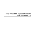
MIDImplant
micro MIDI-2-CV device
version 3.8
USER MANUAL
Roman Sowa 2015
www.midimplant.com
1.
Overview
Thank you for choosing MIDImplant as your new MIDI2CV converter. This short manual will guide you
through installation, and available settings.
The board can be mounted inside any electronic instrument thanks to its small size. No mounting holes
are provided. The strength of connecting wires is enough to secure it in place, as it weighs barely 2
grams. If flexible wires were used, you may add a bit of 2-sided adhesive tape to make sure it does not
get loose, or stick it on a drop of hot-melt glue.
MIDImplant has 2 groups of analog outputs, suitable to control analog synths with V/oct or Hz/V
scaling. MIDImplant comes factory set to 1V/oct scale. CV1 responds to MIDI keyboard on channel 1
and "C" lowest key. CV2 is velocity output. Each CV can be reassigned to different type of MIDI event,
not only keyboard notes - this is described in chapter 5.
The board requires only single power supply, and most important settings are done with use of one
SPST button - it's not part of the delivery, any normally open momentary switch will work. More
settings are accessible via MIDI System-Exclusive commands.
2.
Layout
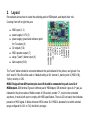
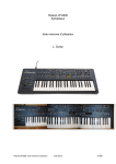
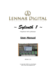
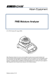
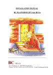
Picture below shows how to locate the soldering pads in MIDImplant, and depicts their role.
Counting from left to right they are:
●
●
●
●
●
●
●
MIDI input (1-2)
power supply 6-17V (3)
power supply ground and reference point
for CV outputs (4)
CV outputs (5-6)
MIDI repeater output (7)
setup ("Learn") button input (8)
Gate outputs (9-10)
The “Learn” button should be connected between the pad indicated in the picture, and ground. You
don't need it if Sys-Ex will be used or if default setting is OK: channel 1, starting note C (MIDI #36),
1V/oct, velocity on CV2.
MIDI IN signal from DIN socket pins 4 and 5 should be connected to pads 1 and 2 of
MIDImplant. DIN terminal 5 goes to leftmost pad of MIDImplant, DIN terminal 4 goes to 2 nd pad, as
indicated in the picture above. Middle contact of DIN socket, number "2", must not be connected
anywhere, it must be left open to comply with MIDI specification. There is LED on board, that indicates
presence of MIDI signal. It blinks whenever MIDI comes IN. If MIDI is decoded to be within selected
range configured for CV1 or CV2, the blink is stronger.
3.
Power supply
First connect the ground input, as shown in layout diagram. The ground pad should be connected with
reasonably thick wire to the same reference ground that was used to measure all voltages during
calibration of your synthesizer. The quality of ground connection directly affects the quality of
generated Control Voltage. It's the reference point of CV outs and if there is any noise or voltage offset
at your selected ground source, it will be directly transformed to errors in pitch. However, you may
compensate small DC offsets via SysEx. See chapter 6.9. for details
MIDImplant is designed to work with typical supply voltages present in any electronic instrument. It
requires only one positive supply line, and voltage range from +6V up to +17V, preferably +12V to
+15V. Current drawn is about 2mA. It can be taken from any place inside the synth, as long as it does
not exceed 17V. Power input must be DC. Connecting AC power, or reversing the power leads
will immediately damage the board.
4.
CV/gate outputs
MIDImplant has 2 sets of outputs. CV outputs have series resistance of 100 ohms and should be
connected to resistance of 100k to achieve calibrated precision in 1V/oct setting. It is possible to use it
with other loads, but no less than 10k, otherwise it may be difficult to reach full range (5V) and
maintain precision. Usually CV inputs have 100k impedance, so it's perfectly OK. If MIDImplant is
destined for a box/module with CV jacks, you should consider adding voltage buffers. Gate
outputs use high-side transistor with 1k output resistor. Gate signal amplitude is equal to the voltage of
power supply (6..17V).
4.1. CV outputs
Each CV output can be configured to respond to one MIDI event. Both outputs are independent to
some extent. The only case when they work in conjunction is CV1 configured as MIDI notes. CV2 then
becomes Velocity output for the notes played by CV1. It is possible then to change CV2 to something
else, but CV2 always becomes velocity right after programming CV1 as MIDI notes.
All available MIDI events represented in Control Voltage are listed below:
● Note on/off (with PitchBend)
● Note velocity - possible only in CV2
● Pitch Bend
● Continuous Controller
● Program Change
● Channel After Touch
● Polyphonic After Touch
Control Voltage varies from 0V up to 5V. It makes 61-note range for 1V/oct scale. If CV is configured
as MIDI event different than notes, 0V represents lowest MIDI value, and 5V is output when highest
MIDI value is received.
All controllers are converted to voltage as one of 128 levels, except Pitch Bend, working with full MIDI
resolution (16384 steps). Neutral position of Pitch Bender gives 2.5V at the output. Note on/off can
output 61 levels of voltage at most. By default MIDI Pitch Bend affects note CV, with full range of
+/-2 semitones at 1V/oct scale. This can be turned off if you want to have full range Pitch Bend voltage
at the other CV. Bent notes cannot go below 0V, or above 5V, so 2 lowest and 2 highest notes from 5octave keyboard will obviously have limited bend range.
For note on/off, CV scale can be adjusted in a wide range, from 0.47V/oct to over 2V/oct if using
settings button, and from 0 to 1.9V/oct via Sys-Ex. If the scale is higher than 1V/oct, there is no room
for 61 keys in 5V range. Every note higher than that gives 5V at CV output. It is possible (by Sys-Ex
only) to reverse voltage response, so lowest note gives 5V output, and top note gives 0V. This may
be helpful in synth circuits, where reversed response control input can be added easier than the
straight one.
When configured in Hz/V scale, the voltage always reaches 4V at the top note, which is often treated
by Hz/V synths as standard voltage required to reach top “C” note on the keyboard. The lowest note
may start at 5 different levels (from 0.125 to 2V), depending on number of octaves chosen. This is
described in chapter about tuning (5.3-5.4).
4.2. Gate outputs
Each Gate output associated with CV output generates voltage indicating the duration of MIDI note.
When MIDImplant is configured to respond to MIDI notes, gate output remains at 0V when no notes
are playing. It then goes up to the supply voltage level, and stays there until all notes are released, as
in typical V-trigger mode. It is possible to reverse the Gate signal individually for each output, so note
on is then at 0V, and note off is at power supply level. By default Gate output re-triggers on next
note if previous one is still on (i.e. when playing legato). Gate is turned off for very short time (0.5ms)
which is usually enough to re-trigger envelopes etc. It's also possible to re-trigger on note off, so when
you release any key, gate will re-trigger if there was any held note still.
Re-trigger can be turned off completely if you want to have flat gate signal as long as any note is
playing.
All those settings are done by SysEx only.
If CV is configured to anything else than notes, associated Gate stays off at all times.
4.3. MIDI repeater output
This output can be used to add MIDI THRU to your MIDI2CV device. The signal available here is
regenerated and MIDImplants can be chained using this option without limits. This is not actual MIDI
THRU, because it introduces slight delay, and chaining dozens of MIDImplants may cause noticeable
delays. To comply with MIDI standard, MIDI repeater output must be connected to lead number 5 of
THRU DIN socket, while contact “4” of the socket must be connected via 220 ohms resistor to +5V
source. MIDImplant cannot provide +5V for that purpose, so the voltage must be taken from
elsewhere, for example 78L05 regulator supplied from the same power supply as MIDImplant.
Connector “2” of THRU DIN socket should be connected to ground.
5.
User settings with "Learn" button
After successful installation, you can set up the MIDI events associated with each CV output. To do so,
your synth must be powered on, and “Learn” button connected (see the layout). There are only 4
parameters to set this way:
1. channel and MIDI event for CV1/gate1
2. channel and MIDI event for CV2/gate2
3. Keyboard scale select (common for both CVs)
4. V/oct fine tuning (common for both CVs)
To select which parameter you want to edit, press the setup button appropriate number of times. Press
once for setting CV1, twice for CV2, 3 times for scale select or 4 times to fine tune the scale. There's no
time limit for pressing the "Learn" button several times. But don't push it too fast, because it may be
treated as contact bounce, and ignored.
All user settings are memorized in nonvolatile memory, taking power off does not reset anything to
defaults, the settings are kept as they were last entered.
5.1. Channel and event of CV1 and Gate1
1. press "Learn" button once
2. generate MIDI event from your device connected to MIDImplant
If it's going to be Pitch Bend, CV1 will be set as such with first movement of your Pitch Bend wheel. It
will then follow your Pitch Bend movement by outputting voltage proportional to what is happening
with the Pitch Bender. Same applies to all other controls except notes.
If it's going to be note on/off, you must play the lowest note of your keyboard to be associated with
CV1. With next note played, CV1 will output voltage determined by MIDI note combined with
PitchBender position (range +/-2 semitones at 1V/oct), and Gate1 will go high whenever there's any
key pressed. At the same time CV2 will represent the value of note Velocity
5.2. Channel and event of CV2 and Gate 2
1. press "Learn" button twice
2. generate MIDI event from your device connected to MIDImplant
If it's going to be Modulation, CV2 will be set as such with first movement of your Modulation wheel. It
will then follow your Modulation movement by outputting voltage proportional to what is happening
with the wheel. Same applies to all other controls except notes.
If it's going to be note on/off, you must play the lowest note of your keyboard to be associated with
CV2. With next note played, CV2 will output voltage according to MIDI note, and Gate2 will go high
whenever there's any note pressed.
You should never assign the same keyboard to both CVs. Only CV1 will work then. You can have two
independent note CV outputs only if each of them is played in different MIDI channel.
The only way to have 2 note CV outputs is to setup CV1 first, and then CV2. Setting CV1 as note on/off
will always change CV2 to velocity output, regardless of how it was programmed before.
5.3. Keyboard scale select
MIDImplant comes factory calibrated to 1V/oct scale, but you can change it anytime to another V/oct
ratio, or Hz/Volt response. If selected by “Learn” button, the scale is the same for botch channels CV1, and CV2, so if you change it for the keyboard associated with CV1, remember that CV2 will also
work in altered scale. To have V/oct in one CV and Hz/V in the other one, or different V/oct rations in 2
channels, the only way to do it is via Sys-Ex configuration (see chapter 6).
The scale setup applies only to MIDI note on/off events. All other controls always use full 0-5V range
for MIDI parameter value. No scaling is available for those.
To change the scale of your note CV, you must have the keyboard already associated to CV1. If it's
already done, do the following:
1. press the “Learn” button three times
2. press a key on your MIDI keyboard to select the scale. 5 lowest notes are reserved for fixed
scales like Hz/V, while notes above set V/oct scale in the following way, assuming 5 octave
keyboard with lowest note "C":
▪
"C" sets the scale to Hz/V and 1 octave span (CV range 2 - 4V)
▪
"C#" sets the scale to Hz/V and 2 octaves span (CV range 1 - 4V)
▪
"D" sets the scale to Hz/V and 3 octaves span (CV range 0.5V - 4V)
▪
"D#" sets the scale to Hz/V and 4 octaves span (CV range 0.25V - 4V)
▪
"E" sets the scale to Hz/V and 5 octaves span (CV range 0.125 - 4V)
▪
"F" sets the scale to factory calibrated 1V/oct, with lowest pitch errors
▪
"F#" is the low end of variable scale and sets it to about 0.47V/oct
▪
top "C" sets 2.05V/oct. Any key in between lowest "F#" and top "C" may be selected for
different scales. Middle "C" (25th key) sets nearly 1V/oct
3. if V/oct was selected, CV output will show the scale and it can be measured with voltmeter. If,
for example you've selected 1V/oct by pressing 25th key, it will read 1V. For Hz/V scale, CV is
set according to played note.
Every note played after this procedure will be converted according to newly selected scale. This
procedure can be repeated many times, until you find proper scale. You can fine tune V/oct scale later,
but coarse setting done here should rather be slightly lower than needed, because fine tuning can only
increase the scale a bit as that's not "+/-" fine tuning.
5.4. V/oct fine tune
After you've selected the scale as described before, you may want to fine adjust it to match your
expectations within single mV per octave. Fine tuning is only available for V/oct scales. Hz/V scales are
factory calibrated to maximum 1 cent of tuning error over entire keyboard range and cannot be
adjusted by the user.
To enter fine tuning mode, do the following:
1. press the "Learn" button four times
2. select fine adjustments with MIDI keyboard. Lowest note means no adjustment - the scale
remains as set in V/oct scale select procedure. 61th key means increasing the scale of about 2
semitones per whole 5 octaves assuming you're working on 1V/oct scale. Every key in between
sets the fine adjustment proportional to played key position.
3. at this time CV will output new scale value to be measured with voltmeter. This is the value for
only 1 octave, and to achieve full accuracy, you may then want to measure the voltage after
playing a key that is 3 or 4 octaves higher than the lowest one.
More precise tuning is possible via Sys-Ex.
6.
User settings via System-Exclusive
All settings described in chapter 5 are also accessible via MIDI System-Exclusive messages. But Sys-Ex
is the only way to set them separately for each CV output. The command's structure is as follows:
● F0 - Sys-Ex header
● 00 20 7A - manufacturer ID for “MIDI-hardware”
● 01 - device ID for MIDImplant
● 01-02 - CV output ID
● 01-08 – command
● associated parameters (length varies for different command)
● F7 - Sys-Ex footer.
This is described in details here. All numbers are represented in hexadecimal format. You may use
any kind of Sys-Ex editor to send those commends to MIDImplant. MIDI-OX (midiox.com) or SendSX
(bome.com) are good examples.
At www.midimplant.com/config3.html you can find easy to use tool for selecting every parameter of
MIDImplant. It creates standard MIDI file, that can be played towards MIDImplant and set all desired
parameters without need for any knowledge of System Exclusive, or special editor. The file can be
transfered to MIDImplant from any sequencer as long as it has Sys-Ex transmission enabled.
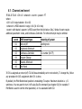
6.1. Channel and event
F0 00 20 7A 01 <CV> 01 <channel> <event> <param> F7
where:
<CV> is CV output selector: 01 or 02
<channel> is MIDI channel in range 1-16 (01-10 in hex)
<event> with related <param> is MIDI event from the list below. Only 2 kinds of event require
additional parameter: notes, and Continuous Controller. For others this byte may be omitted.
event
MIDI event type
meaning of param
01
Note on/off
starting note
02
Polyphonic Aftertouch
-
03
Continuous Controller
CC number (00-7F)
04
Program Change
-
05
Channel Aftertouch
-
06
Pitch Bend
-
If CV1 is assigned as note on/off, CV2 will be automatically set to note velocity. To change this, follow
any procedure for CV2 assignment after CV1 is done.
By default, the Pitch Bend wheel position is modulating CV output. Maximum deviation is +/-2
semitones. You may want to turn it off using Sys-Ex command (see chapter 6.6) for example if
PitchBend is used to control other parameter, or it is associated with CV2.
6.2. V/oct scale tune
F0 00 20 7A 01 <CV> 02 <MSB> <LSB> F7
where:
<CV> is CV output selector: 01 or 02
<MSB> is most significant byte of tuning scale. Possible values 00-7F
<LSB> is least significant byte of tuning scale. Possible values 00-7F
Both parameters combine to 14-bit value of tuning ratio. Tuning is adjusted in steps of about 0.12mV
per octave in range from 0 to 1.9 V/oct. The MSB/LSB parameters are calculated according to the
formula:
TUNE = 8710 * [V/oct]
MSB = integer of (TUNE / 128)
LSB = TUNE - MSB * 128
for example 1.2V/oct needs (in decimals) MSB=81, LSB=84, 1V/oct MSB=68, LSB=6 while 0.32V/oct
needs MSB=21, LSB=99, so converted to hexadecimal values it would look like this for CV1:
1.2V/oct - F0 00 20 7A 01 01 02 51 54 F7
1V/oct - F0 00 20 7A 01 01 02 44 06 F7
0.32V/oct - F0 00 20 7A 01 01 02 15 63 F7
For each MIDImplant, and each installation, actual numbers needed to achieve given scale may differ
slightly, this is only a guideline and starting point for final tuning. You should always check entire
keyboard range with a tuner or frequency meter if tuning needs finer adjustments, and not rely solely
on this equations. There's also offset trim possible for each CV individually – see chapter 6.9. Scale and
offset settings work in conjunction the same way as relevant trimmers in any VCO circuit. Sometimes
the scale is called “width”, while offset can be called “tune”.
6.3. V/oct and Hz/V scale select
F0 00 20 7A 01 <CV> 03 <select> F7
where:
<CV> is CV output selector: 01 or 02
<select> takes one of 7 possible values:
00: set CV output to variable V/oct scale tuned by parameter described in 6.2.
01 - 05: set CV output to Hz/V scale and define how many octaves are accessible.
06: set CV output to fixed, calibrated 1V/oct scale
In Hz/V mode <select>=01 sets only one octave range and lowest voltage is 2V. <select> = 05 means
5 octave range with starting note at 0.125V. Although MIDImplant is factory calibrated to match Hz/V
response within +/-1 cent over full 5-octave range, it may be sometimes desirable to limit the number
of octaves and start with higher voltage to achieve best accuracy at lowest notes.
When <select> = 6, the CV turns to factory calibrated 1V/oct scale (at 100k load) with lowest possible
tuning errors. Variable V/oct scale tuned as described in chapters 5.3, 5.4 and 6.3 exhibit slightly
bigger errors, within +/-2 cents over 5-octaves span.
6.4. Gate polarity
F0 00 20 7A 01 <CV> 04 <polarity> F7
where:
<CV> is CV output selector: 01 or 02
<polarity> takes one of 2 possible values:
00: Gate during note-on is at power supply voltage, when all notes are off - at 0V
01: Gate during note on is at 0V, when all notes are off - at power supply voltage.
6.5. Off Velocity ignore
F0 00 20 7A 01 02 05 <off-velocity> F7
where:
<off-velocity> takes one of 2 possible values:
00: velocity is updated on both, note-on, and note-off events
01: velocity is updated only at note-on, and ignored at note-off (remains unchanged)
If your keyboard detects key release velocity, CV2 by default will set the voltage according to what it
gets either at at note-on or note-off. To keep it at note's attack level, use this setting.
6.6. PitchBender combined with Notes
F0 00 20 7A 01 <CV> 06 <pbend> F7
where:
<CV> is CV output selector: 01 or 02
<pbend> takes one of 2 possible values:
00: Pitch Bend is affecting pitch voltage (default)
01: pitch voltage is determined only by notes
If CV is assigned to notes, its voltage also varies depending on Pitch Bend of the same channel. Full
Bend range is 2 semitones up and down from the note's voltage. If you want to use Pitch Bend for
other controls, or want to have full resolution Bend on 2nd CV, then you should turn this feature off, so
the voltage stays unchanged regardless of Bender's movement.
6.7. Reversed pitch voltage
F0 00 20 7A 01 <CV> 07 <polarity> F7
where:
<CV> is CV output selector: 01 or 02
<polarity> takes one of 2 possible values:
00: standard operation, lowest note at 0V, 61th key at 5V or less, depending on scale ratio.
01: reversed voltage, top note at 0V, lowest note at 5V or less, depending on scale ratio.
Reversed pitch voltage can only be set for V/oct scales.
6.8. Gate re-trigger
F0 00 20 7A 01 <CV> 08 <re-trigger> F7
where:
<CV> is CV output selector: 01 or 02
<re-trigger> takes one of 3 possible values:
00: Gate output is on as long as any note is playing
01: Gate output goes off for 0.5ms at each note on or off in legato group
02: Gate output goes off for 0.5ms in legato only when new note starts (default)
6.9. CV offset
F0 00 20 7A 01 <CV> 09 <offset> F7
where:
<CV> is CV output selector: 01 or 02
<offset> determines little voltage offset applied to CV output, takes any value between 00 and 7F
00: most possible negative offset of about -9mV
40: no offset, default state
7F: most possible positive offset of about +9mV
Offset is adjusted in steps of about 0.15mV and can be very usable especially in Hz/V tuning, where
lowest notes differ only by a few mV. If you use voltage buffers at CV, this allows for compensation of
the offsets caused by the buffers, so you may use cheaper components.
6.10. Reset to factory defaults
Send the following System-Exclusive sequences, with short delays or separately, to go back to default
settings:
F0 00 20 7A 01 01 01 01 01 24 F7 – notes in CV1, velocity in CV2
F0 00 20 7A 01 01 03 06 F7 – 1V/oct calibrated scale for CV1
F0 00 20 7A 01 02 03 06 F7 – 1V/oct calibrated scale for CV2
F0 00 20 7A 01 01 04 00 F7 – normal Gate1 polarity
F0 00 20 7A 01 02 04 00 F7 – normal Gate2 polarity
F0 00 20 7A 01 02 05 00 F7 – velocity CV changes at note on and off
F0 00 20 7A 01 01 06 00 F7 – Pitch Bender affects notes at CV1
F0
F0
F0
F0
F0
F0
F0
00
00
00
00
00
00
00
20
20
20
20
20
20
20
7A
7A
7A
7A
7A
7A
7A
01
01
01
01
01
01
01
02
01
02
01
02
01
02
06
07
07
08
08
09
09
00
00
00
02
02
40
40
F7
F7
F7
F7
F7
F7
F7
–
–
–
–
–
–
–
Pitch Bender affects notes at CV2
normal dependency of voltage against note at CV1
normal dependency of voltage against note at CV2
Gate1 re-triggers in legato
Gate2 re-triggers in legato
CV1 offset 0mV
CV2 offset 0mV
You should never, in any case, send all Sys-Ex sequences immediately in one go. It needs at
least 10ms delay between the commands, so if your Sys-Ex editor does not allow for introduction of
short delays, send each of the sequences separately.
The best way to do it is via on-line configurator at www.midimplant.com/config3.html. When you go to
that page, select needed parameters from drop down lists, and click "create MIDI file". Then play that
file to MIDImplant and all the configuration is done and saved. Default selection of parameters in that
page will turn the MIDImplant to its factory settings.