1
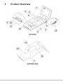
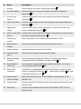
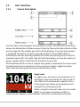
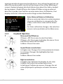
User Manual
Cobia Flex R/F
English - v2014.3A
NOTICE
RTI Electronics AB reserves the right to make changes to the Cobia
Flex R/F and the information in this user manual without prior notice.
RTI Electronics AB assumes no responsibility for any errors or
consequential damages that may result from the use or
misinterpretation of any information contained in this user manual.
Copyright © 2011-2014 by RTI Electronics AB. All rights reserved.
The content of this document may not be reproduced for any purpose
other than supporting the use of the product, without prior
permission from RTI Electronics AB.
User Manual Downloads
You can download user manuals here: www.rti.se/downloads
2
Cobia Flex R/F - User Manual 2014.3A
Contents
1.
Product Overview
..............................................................................................................
4
1.1
User Interface
............................................................................................................6
1.1.1
1.1.2
2.
Getting Started
..............................................................................................................
9
2.1
2.2
3.
Before Starting
............................................................................................................
the Cobia for the First Time
9
Charging the
............................................................................................................
Battery
9
Performing a..............................................................................................................
Measurement
10
3.1
3.2
3.3
3.4
Measuring ............................................................................................................
with the Internal Detector
10
Measuring ............................................................................................................
with an External Detector
11
Measuring ............................................................................................................
with a Light Probe
12
Measuring ............................................................................................................
with the Optional Internal MAS
13
3.4.1
3.4.2
4.
4.1
4.2
4.3
5.
5.1
5.2
5.3
6.
7.
Screen Description
...........................................................................................66
Keyboard Operation
...........................................................................................88
Connecting the
...........................................................................................14
MAS Cable
14
Tube Current
...........................................................................................15
Safety Precautions
15
Maintenance..............................................................................................................
16
Scheduled Calibration
............................................................................................................
16
Updating the
............................................................................................................
System
16
Changing the
............................................................................................................
Battery
17
Technical Data
..............................................................................................................
17
Battery Charging
............................................................................................................
Details
17
Battery Warnings
............................................................................................................
17
Communicating
............................................................................................................
with a PC
18
Troubleshooting
..............................................................................................................
18
Standards and
..............................................................................................................
Compliances
19
Cobia Flex R/F - User Manual 2014.3A
3
1
Product Overview
TOP VIEW
BOTTOM VIEW
4
Cobia Flex R/F - User Manual 2014.3A
#
Name
Description
1
Display
Cobia display. See section Screen Description
2
Up arrow button
Used to move up in the user interface. See section Keyboard
Operation 8
3
Down arrow
button
Used to move down in the user interface. See section Keyboard
Operation 8
4
Left arrow button Used to move left/back in the user interface. See section Keyboard
Operation 9
5
Right arrow
button
6
Menu and On/Off Used to start and power off the Cobia, and display the system menu.
button
See section Keyboard Operation 8
7
Positioning
marker
Marks the depth of the radiation measurement surface
8
Measurement
surface
Circular entrance surface for the measurement sensors
9
Status indicator
Indicates functional status of the Cobia
6
Used to move right or make a selection in the user interface. See
section Keyboard Operation 8
10 External probe
input
Used to attach external measurement probes
11 Battery charging
indicator
The orange battery charging indicator is lit when the battery is
charging. See section Battery Charging Details 17
12 Optional MAS
connector
Used to attach invasive MAS cable (selected models). See section
Connecting the MAS Cable 14
13 Micro-USB
connector
Used both to charge and to connect the Cobia to a computer. See
sections Charging the Battery 9 , Updating the System 16, and
Communicating with a PC 18
14 Measurement
center marking
Marks the center position of the radiation measurement on the
bottom side
15 Product label
Displays detailed information about the product and model (on the
bottom side)
16 Reset hole
Used to do a hardware reset of the Cobia. Marked "RST"(on the
bottom side)
Cobia Flex R/F - User Manual 2014.3A
5
1.1
1.1.1
User Interface
Screen Description
A status field is displayed at the top of the screen. The left side of the field
shows the Radiation or Measurement Quality Code and a description of the
active range (1).The middle part of the field displays icons for when power
is supplied and when an external probe and/or internal MAS cable is
attached as well as warning symbols for when any settings are set to nonstandard values (2). The right side of the field displays an icon for external
power supply and an indicator for the battery level (3).
At the bottom of the screen a simple user guide is displayed. For each view,
the buttons that are functional in this view are shown, together with a
short text describing the function of the buttons (4-6).
Single view
In single view, only one active parameter is
displayed, represented by the value and its
unit. Each unit is shown by a specific color.
Pressing the up / down arrow buttons will
change the active parameter.
When using the internal tube current socket
(MAS) or an external detector (EXT) an
indicator will appear in the leftmost side of the unit field (not shown).
6
Cobia Flex R/F - User Manual 2014.3A
Located to the left of the value, two symbols may be visible:
1. A play symbol (triangle) is visible during the
measurement. It is filled (green) during the radiation
detection, and will then stay contoured while the Cobia
accepts continued measurement during Restart Delay.
1B. When using the optional parameter cycling, a
rotating indicator will appear just above the play
symbol.
2. A pulse indicator is shown below the play symbol.
This indicator is turned on when pulses are detected,
resulting in display of additional pulse parameters.
List view
In the List view, all the available parameters
are shown simultaneously. The active
parameter (displayed in Single view) is
indicated in color.
If a measurement is started when the Cobia
is in List view, the display will switch to
Single view during the measurement
and then return to List view after completion. Parameters from MAS or EXT
are marked accordingly.
Note! The available parameters may vary depending on the model of the
Cobia. The example picture shows a pulsed measurement with Cobia Flex
R/F kV & Dose.
Main Menu view
The Menu view displays a set of available
functions, selected by pressing the right
arrow button. Reset Measurement zeroes and
resets the meaurement. Prev. Measurements
recalls the results of earlier measurements.
Settings is for viewing and modifying the
measurement settings. Preferences is for
Cobia Flex R/F - User Manual 2014.3A
7
viewing and adjusting personal preferences. Any setting change that can
affect the measurement results will be shown in the status field (top of
screen). System Info gives detailed information about the Cobia, needed
during support. Power Off turns the Cobia off. When using an external
detector or probe, there will be an extra menu item, Ext.Detector, that
displays detector information and settings as described below.
Select External Detector Calibration
When an external detector containing more
than one calibration is connected to the
Cobia, a selection screen will be shown
(left).
For later calibration changes, the selection
screen is also available on the Main menu.
1.1.2
Keyboard Operation
Menu and On/Off button
If Power = Off: Press once to start the Cobia
If Power = On: Press once to display the menu. Press
and hold to switch off the Cobia
In Menu: Closes the menu
Up and Down arrow buttons
In Single view: Changes the active parameter shown.
In List view: Changes the highlighted (active)
parameter
In Menu: Moves the marker
Right arrow button
In Single view: Switches the display to List view
In Menu: Activates the marked menu item
In Setting or Preferences menus: Changes the set
value (displayed in yellow) or activates the menu
item
8
Cobia Flex R/F - User Manual 2014.3A
Left arrow button
In List view: Switches the display back to Single view
In Menu: switches the display back to the previous
menu or screen
2
2.1
Getting Started
Before Starting the Cobia for the First Time
Before using the Cobia for the first time, the unit has to be charged for 16
hours. See Charging the Battery 9 .
2.2
Charging the Battery
The battery can be charged in two ways:
Via the USB cable connected to a PC. The charging is not disturbed by
communication between the PC and the Cobia.
Via the USB cable connected to the included external charger.
Cobia Flex R/F - User Manual 2014.3A
9
3
3.1
Performing a Measurement
Measuring with the Internal Detector
The pictures below show how to position the Cobia in different types of Xray units.
A = Radiography X-ray unit
B = Dental X-ray unit
1. Start the X-ray unit.
2. Prepare the X-ray unit for test of desired settings.
3. Start the Cobia.
4. Place the Cobia under the X-ray source at a clinically relevant distance
(typically 50 - 100 cm from the source).
5. Make sure that the radiation field covers (at least) the entire Cobia
detector surface.
6. Start an exposure.
7. When the measurement is over, the recorded values are by default
cycled on the Cobia display. Press the Right arrow button to go to the List
view for an overview.
8. Compare the parameters displayed by the Cobia with the test settings
for the X-ray unit.
9. Record the results.
10.To repeat, adjust settings and start over from Step 6.
10
Cobia Flex R/F - User Manual 2014.3A
3.2
Measuring with an External Detector
The description below describes how to use an external detector with the
Cobia.
1. Start the X-ray unit and Start the Cobia.
2. Set up the external detector unit. For an external dose probe, place the
detector at a clinically relevant distance (typically 50 - 100 cm from the
source), as described by the manual of the detector.
3. Attach the external detector to the Cobia.
4. If needed, select among the available calibrations (shown below).
5. Adjust the X-ray unit to the desired settings.
6. Start an exposure (or other signal).
7. When the measurement is over, the recorded values are by default
cycled on the Cobia display. Press the Right arrow button to go to the List
view. All measurement resulting from the external input is marked with
an EXT symbol.
8. Record the results.
9. To repeat, start over from Step 5.
Cobia Flex R/F - User Manual 2014.3A
11
3.3
Measuring with a Light Probe
In-depth instructions on using a Light Probe are found in the separate Light
Probe manual.
Attach the light probe monitor adapter (picture below, left) for measuring
the luminance of a monitor or light box, or the lux adapter (below right) for
measuring illuminance (ambient light).
Position the probe in the desired location and read the result.
When using the luminance adapter, the recorded value is automatically
saved to the log function. For illuminance measurements, the down arrow
button has to be pressed for a value to be saved to the log.
Please note that there is no need to perform a reset before using the Light
probe.
More information is available in the guide for Measuring with an External
Detector 11 .
12
Cobia Flex R/F - User Manual 2014.3A
3.4
Measuring with the Optional Internal MAS
The description below describes how to use the optional internal MAS
cable with the Cobia Flex R/F + MAS model.
CAUTION!
Users of Invasive mAs meters must be aware of the
potential damage to generators and electrical human
hazards in the case of improper connection or failure of any
part of the meter circuit. The Cobia MAS is intended for use
only by those skilled in the calibration and repair of X-ray
machines. Please read the section Tube Current Safety
Precautions 15 for more safety rules.
1. Prepare the unit that is to be tested.
2. Connect the Cobia MAS Cable, as described in section Connecting the
MAS Cable 14 .
3. The tube current parameters are added to the List View, as shown
below.
Cobia Flex R/F - User Manual 2014.3A
13
4. Start an exposure.
5. When the measurement is over, the recorded values are by default
cycled on the Cobia display. Press the Right arrow button to go to the List
view. All measurement results from the internal MAS input is marked
with a MAS symbol (shown below).
6. Record the results.
7. To repeat, change settings and start over from Step 5.
3.4.1
Connecting the MAS Cable
Please be aware that high voltage may occur if the mAs probe is not
properly connected. Read the Tube Current Safety Precautions 15 section
before starting the measurement.
1. Power down the X-ray generator and wait the recommended time to
allow for generator discharge according to generator manufacturer's
specifications.
2. Remove the jumper of the mAs measuring socket of the generator.
3. Connect the Cobia MAS Cable to the mAs measuring socket using the
included safety cables, observing the polarity (see picture below). If
needed, use included adapters.
14
Cobia Flex R/F - User Manual 2014.3A
High Voltage X-ray Transformer
mAs measuring socket
Cobia MAS Cable
Tube current ground return line
4. Connect the other end of the Cobia MAS Cable to the MAS input of the
Cobia Flex R/F.
Caution!
Do not forget to replace the mAs socket jumper when
removing the Cobia MAS Cable.
3.4.2
Tube Current Safety Precautions
Only use the Cobia Internal MAS if you are authorized and skilled to make
invasive measurements using the X-ray generator mAs measuring socket.
Please be aware that high voltage may occur on the Cobia Internal MAS if
the cable connection to the X-ray generator mAs socket is broken. Always
wait approximately one minute after switching off the X-ray generator
before connecting or disconnecting the cables between the Cobia Internal
MAS and the mAs measuring socket.
Always check that the short circuit path (jumper) normally connected to
the mAs measuring socket is reapplied after the use of the Cobia Internal
MAS and before the X-ray generator is switched on again.
Important!
Do NOT connect the Cobia Internal MAS to the filament current circuitry.
The Cobia Internal MAS is only intended to measure the tube mA and
Cobia Flex R/F - User Manual 2014.3A
15
mAs.
Do NOT use the Cobia Internal MAS in contact with a patient.
Do NOT use Cobia Internal MAS on a circuit with a voltage higher than
90 V DC or 600 V AC.
Do NOT expose the instrument to direct sunlight, extremes of
temperature and humidity, or dew fall.
Do NOT exceed maximum tube current input (1000 mA).
Note!
The Cobia Internal MAS is intended for service and quality
control of diagnostic X-ray equipment. It is not intended for
use during diagnostic examinations of patients.
RTI Electronics AB takes no responsibility for misuse of the Cobia Internal
MAS or use together with products that the Cobia Internal MAS is not
intended for.
RTI Electronics AB assumes no responsibility in case of customers not
following these safety precautions.
4
4.1
Maintenance
Scheduled Calibration
RTI recommends that the Cobia is recalibrated every 24 months. Send your
Cobia to your local RTI distributor, who will send it to our service
department in Mölndal, Sweden, or New Jersey, USA. For contact details,
please see the back of this manual or the list of local RTI distributors on the
RTI website (www.rti.se).
4.2
Updating the System
Updates can be performed by the user. The system firmware or software is
updated by downloading the latest versions from www.rti.se/downloads.
Instructions are included in the download or can be found in the reference
manual.
16
Cobia Flex R/F - User Manual 2014.3A
4.3
Changing the Battery
The battery is a customized rechargeable battery. That can only be
replaced by RTI authorized service centers.
5
Technical Data
5.1
Battery Charging Details
The section Charging the Battery 9 describes how the Cobia battery is
charged.
On the front face of the Cobia, there is an orange battery charging
indicator, marked
. The indicator is lit when the battery is actively
charging. It will gradually turn off when the battery is getting closer to fully
charged.Charging is possible also when the Cobia is powered off.
Approximate battery charging times:
Capacity
Using power supply
100%
90%
80%
50%
5h
3.5 h
2.5 h
1.5 h
5.2
Computer USB,
Cobia ON
8.5 h
7h
6h
3.5 h
Computer USB, Cobia
OFF
32 h
30 h
27 h
17 h
Battery Warnings
When the battery is starting to run low, warnings are shown (see below).
After the second warning the system can shut down suddenly, due to an
empty battery.
Cobia Flex R/F - User Manual 2014.3A
17
5.3
Communicating with a PC
The Cobia Flex R/F includes a user-friendly communication protocol,
allowing communication between the Cobia Flex R/F and a computer. The
protocol can also be integrated into other software. The protocol is
described in detail in the Reference manual.
6
Troubleshooting
If experiencing problems with the Cobia, please go through the following
steps before contacting your local RTI distributor or RTI Electronics:
A. Check the RTI website for system updates (www.rti.se).
B. Go through the checklist below.
The Cobia does not start:
If the Cobia does not start, try the following: Connect the charger and
retry to start the Cobia. If it does start, the battery was too low to start. If
this does not help, try to reset the Cobia as described below.
The Cobia indicates a dose lower than anticipated:
If the dose readings are too low or if the irradiation times for short
exposures are too short check that the measurement is performed so
that the radiation is perpendicular to the Cobia detector surface. Please
also make sure that the entire surface is evenly irradiated.
The Cobia gives "Field Error":
The Cobia detector surface needs to be properly irradiated. Please make
sure that the entire surface is irradiated, and that nothing is blocking the
radiation.
The external detector gives false readings:
The external detector cable is very sensitive when using certain probe
types. Try not to move the detector while attached to the Cobia. To reset
false readings, use the Reset Measurement on the main menu.
18
Cobia Flex R/F - User Manual 2014.3A
How do I reset the Cobia?
There is a reset hole on the bottom face of the Cobia, marked RST. Insert
the end of a paper clip or similar to reset the Cobia.
7
Standards and Compliances
For standards and compliances, see the Reference Manual.
Cobia Flex R/F - User Manual 2014.3A
19
Contact Information World Headquarters
Contact Information US Office
RTI Electronics AB, Sweden
Flöjelbergsgatan 8 C
SE-431 37 MÖLNDAL, Sweden
Phone: +46 31 7463600
Fax: +46 31 270573
RTI Electronics Inc, USA
33 Jacksonville Road, Bldg. 1,
Towaco, NJ 07082, USA
Phone: 1-800-222-7537
(Int. +1-973-439-0242)
Fax: Int. +1-973-439-0248
Sales: [email protected]
Support: [email protected]
Service: [email protected]
Sales: [email protected]
Support: [email protected]
Service: [email protected]
Web: www.rti.se
Web: www.rti.se
RTI article number: 4760.001206