1
OPERATING INSTRUCTIONS
for the
Model CT-3500TM
Circuit-Breaker Timer
Part Number VIC-35000
Vanguard Instruments Company
1710 Grevillea Court
Ontario, California 91761
TEL: (909) 923 9390
FAX: (909) 923 9391
September 2001
Rev. 0
Model CT-3500
Operating Procedures
SAFETY SUMMARY
The following safety precautions must be
observed during all phases of test set-up, test
hookups, testing, and test-lead disconnects.
Do Not Modify Test Equipment
Because of the added risk of introducing
additional or unknown hazards, do not install
substitute parts or perform any unauthorized
modification to the equipment. To ensure that
designed safety features are maintained, it is
recommended that all equipment repairs be
performed at Vanguard Instruments Co. or by
an authorized repair-service. Unauthorized
equipment modifications can create unknown
safety hazards and will void the warranty.
Do Not Service or Test Alone
Do not perform test procedures or service
unless another person is also present who is
capable of rendering aid and resuscitation.
Avoid Contact with High Voltage
Because electrical utility station environments
contain high voltages and currents, there is
always the possibility of personal contact with
an unexpected lethal voltage generated by
magnetic induction and electrostatic leakage
from nearby live circuitry. When test units
are connected to deenergized ("dead") power
lines, regardless of how short they are, always
discharge the lines before attaching any test
lead. Because of the possibly deadly
consequences of physical contact with such
high-voltage lines, engineers and technicians
must always treat electrical equipment and
hookups as though a lethal condition will
eventually occur. Therefore, no matter how
unlikely it may seem, never assume anything
about the safety of any test setup.
Ensure the safety of all personnel by
checking first-hand to eliminate every
possible hazard!
Follow Exact Operating Procedures
Any deviation from operating procedures
described in this manual may create one or
more safety hazards, damage the unit, or
cause test errors; Vanguard Instruments Co.
assumes no liability for unsafe or improper
use of this equipment or for any collateral
damage to other equipment resulting from
such misuse.
I
Model CT-3500
Operating Procedures
Table of Contents
1.0 INTRODUCTION ...................................................................................................................1
1.2 Applicability.........................................................................................................................1
1.3 Supersedure Notice ..............................................................................................................1
2.0 GENERAL DESCRIPTION....................................................................................................1
2.1 Functional Description.........................................................................................................1
2.2 Furnished Accessories..........................................................................................................1
3.0 CT-3500 SPECIFICATION ....................................................................................................2
3.1 CONTROLS and INDICATORS ........................................................................................3
3.2 CT-3500 LCD Contrast Control..........................................................................................4
3.3 CT-3500 Printer Control......................................................................................................4
3.4 RS-232C Computer-Interface port.......................................................................................4
4.0 PRETEST SETUP ...................................................................................................................5
4.1 Operating Voltage ................................................................................................................5
4.2 CT-3500 Printer Paper.........................................................................................................5
4.3 Test Cable Connections .......................................................................................................5
4.3.1 Contact Cable Connection...............................................................................................5
4.3.2 Trigger Cable Connection................................................................................................5
5.0 Operating Procedures...............................................................................................................8
5.1 Introduction..........................................................................................................................8
5.2 Precautions...........................................................................................................................8
5.3 Preliminary Procedure..........................................................................................................8
5.4 Identification Setup Procedure.............................................................................................8
5.5 Run Test Procedure............................................................................................................10
5.6 Review Shot Procedure......................................................................................................13
5.7 Restore Shot Procedure......................................................................................................14
5.8 Print Test-Record Directory...............................................................................................15
5.9 Computer Interface Procedure ...........................................................................................16
5.10 Set Date and Time..........................................................................................................16
5.11 Set 50/60 Hz Procedure..................................................................................................16
5.12 Cable Test Procedure .....................................................................................................17
II
Model CT-3500
Operating Procedures
Table of Figures
Figure 1.0 CT-3500 Controls and Indicators.................................................................................3
Figure 2.0 CT-3500 Timing Hook-Up Diagram...........................................................................6
Figure 3.0 Trigger Circuit Hook-Up Diagram...............................................................................6
Figure 4.0 Step-by-Step Operating Procedures Flow Diagram.....................................................7
Figure 5.0 A typical CT-3500 OPEN Test print out ...................................................................11
Figure 6.0 A typical CT-3500 CLOSE-OPEN Test print out .....................................................12
Figure 7.0 Typical CT-3500 Shot Directory...............................................................................15
III
Model CT-3500
Operating Procedures
1.0 INTRODUCTION
1.2
Applicability
This manual applies to Model CT-3500™,
manufactured by Vanguard Instruments Co.,
part number CT-35000. This operator’s
manual is intended for personnel who
operate and test utility circuit breakers
(hereafter, breaker).
The CT-3500 stores up to 128 timing (test
shot) records in FLASH EEPROM memory.
Stored timing-measurements and related
data can be displayed and printed in the field
or stored for later review, analysis, or
printing.
A RS-232C serial interface port also
provides for computer interface and
diagnostic test.
1.3
Supersedure Notice
This Operator’s manual is the basic issue for
the Model CT-3500 and does not
supersede any previously published manual.
2.1
Functional Description
CT-3500’s operation (a timing shot) is
started by an input trigger (e.g., a breaker’s
initiating control voltage), which starts all 3
timers at the same instant. Each timer
independently stops after detecting each
contact transition.
Besides measuring contact time each timer
will also measure contact bounce time.
The timing results display in both
milliseconds and cycles. The cycle display is
selectable between 50Hz or 60Hz.
The CT-3500 can be interfaced (via an RS232C interface port) with a IBM-compatible
PC. A software package supplied with the
CT-3500 allows the user to retrieve the test
data stored in the CT-3500 Flash EEPROM.
2.0 GENERAL DESCRIPTION
The CT-3500 Digital Breaker Timer
(henceforth, for brevity, called CT-3500) is
a microprocessor-controlled timer designed
to test electrical-utility circuit breakers.
(The CT-3500 can also time contact
operations of any switching device—e.g.,
switching relays, remotely controlled
contactors, etc.) It contains 3 independent
timers for the simultaneous timing of each
set of contacts in three-phase breakers.
The CT-3500 fully analyzes the timing of
breaker contact operation: OPEN, CLOSE,
OPEN-CLOSE, and CLOSE-OPEN.
It’s field-portable, very rugged, and is easily
operated by first-time users with little
training.
It features a 16-key pushbutton pad for
entering breaker test ID and control
function. A 4-line by 20-character back
lighted LCD displays control menus, and
measured test results.
Test results can be printed on a built-in 2.5
inch-wide thermal printer.
Operation requires little more than
connecting the cables of the CT-3500 to
utility breaker contacts, selecting the desired
test options and enabling the test results to
be stored in a non-volatile memory.
Operations do not require any conversion
calculation, written note, or detailed list of
steps to remember (thus, greatly reducing
any chance of error by the operator).
2.2
Furnished Accessories
The CT-3500 is supplied with the following
accessories:
1. One 15-ft. Trigger Cable.
2. One 15 ft Contact Cable.
3. One 30 ft Extension Cable.
4. One Grounding Cable.
5. One Power Cord.
6. One Cable Carrying Bag.
1
Model CT-3500
Operating Procedures
3.0 CT-3500 SPECIFICATION
(Refer to the specification list in Table 1.)
Table 1. CT-3500 Specifications and Leading Particulars
MODEL
CT-3500
TYPE
Special-purpose utility test equipment ;
Digital Circuit-Breaker Timer
SIZE
15-inches Wide by 7-inches High by 13-inches Deep
WEIGHT
INPUT POWER
Less than 15 pounds
90-120 or 220-240 volts ac (Selectable), 50/60Hz
DRY CONTACT INPUTS
3 channels (continuity detectors)
TRIGGER INPUT
Open/Close: 24 to 300 V, dc/peak ac
OPERATIONS
Open, Close, Open-Close, and Close-Open strokes
RESOLUTION
±1/10 millisecond
ACCURACY
0.1% of reading ±0.1ms
DISPLAY
LCD, back lighted, 4-line-by 20-character; alpha-numeric
CONTROLS
Keypad, 10 alpha-numeric and 6 function pushbuttons
COMPUTER
INTERFACE
RS-232C
PRINTER
Built-in thermal printer (prints on 2.5-inch-wide strip)
ENVIRONMENT
Operating: 0ºC to 55ºC; Storage: -40ºC to 65ºC
SHIPPING CASE
Optional (Hard case with foam liner)
WARRANTY
One Year parts & labor; post-warranty service available
NOTE:
THE ABOVE SPECIFICATIONS ARE VALID AT NOMINAL OPERATING VOLTAGE AND AT A TEMPERATURE OF 25°C (77°F)
THE CT-3500 SPECIFICATIONS MAY BE UPGRADED AND CHANGED WITHOUT PRIOR NOTICE.
2
Model CT-3500
Operating Procedures
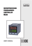
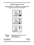
3.1
CONTROLS and INDICATORS
The control-panel is shown in figure 1.
Leader lines point to each item in the figure
with an index number cross-referenced to a
functional description in Table 2.
Figure 1.0
Users should become familiar with these
items before trying to use the CT-3500.
Misuse of the CT-3500 can create serious
hazards and cause loss of data, and
equipment damage.
CT-3500 Controls and Indicators
3
Model CT-3500
Fig. 1
Index #
1
2
3
4
5
6
7
8
Operating Procedures
Table 2. Functional Description of Controls and Indicators
ADJACENT PANEL
FUNCTIONAL DESCRIPTION
MARKING
TRIGGER
Connector, 5-pin, male; trigger input starts CT(300V MAX)
3500 three timers; leads are connected to
breaker-Trip and Close coils. Trigger voltage
ranges from 24 to 300 volts dc or peak ac.
Serial interface-port connector (9-pin, DB type)
RS-232C
lets CT-3500 be controlled by an IBM type PC.
PIN
SIGNAL
2
Tx
3
Rx
5
Signal Ground
none
Display, 4-line by 20-character LCD, backlit;
displays menus, prompts, and test-result data.
120/240 Vac, 1A, 50-60 Hz Input power plug and ON/OFF rocker switch
Threaded grounding stud; 5/16-18 with wing
GROUND
nut; Safety Ground; Must be connected to
station ground before hookup and testing.
none
Built-in thermal printer; prints test result data
on 2.5-inch-wide thermal paper.
none
Keypad; ten alpha/numeric and 6 function keys
(momentary-contact pushbuttons); functions
are: ENTER, START, CLEAR, STOP, Up (∧)
and down (∨)--paper control pushbuttons; used
for test menu selections, and data entries.
Contact cable connector, 16-pin male. Contact
CONTACT
cable contains 3 contact leads (phase A, B, or
C) and one common lead.
3.2
CT-3500 LCD Contrast Control
To Darken the LCD display, press and hold
the “Paper ∧ Contrast” switch for two
seconds; to lighten the LCD display, press
and hold the “Paper ∨ Contrast” switch for
two seconds.
3.4
RS-232C Computer-Interface port
An IBM PC software package is supplied
with each CT-3500 allows the user to
retrieve test records stored in the CT-3500
memory.
3.3
CT-3500 Printer Control
To advance printer paper, press “Paper ∧
Contrast” switch once. Paper will advance
from printer. Press “Paper ∨ Contrast”
switch once, paper will advance backward
from printer.
4
Model CT-3500
Operating Procedures
4.0 PRETEST SETUP
4.1
Operating Voltage
Primary input-power operating voltage is
selectable between 90 to 120 Vac and 220 to
240 Vac.
Unless specified differently at the time of
purchase, the CT-3500 is configured to
operate from a 90 to 120 Vac (default) input.
Changing jumper links on the primary
power strip selects alternate (refer to Table
3) voltage levels
Table 3. Input-Voltage-Selection Jumper Configurations
VOLTAGE SELECTION
J1 JUMPERS
90 to 120 Volts, ac
Pin 1-2 and Pin 3-4
220 to 240 Volts, ac
Pin 2-3
4.2
CT-3500 Printer Paper
The CT-3500 printer uses 2.5-inch wide
thermal paper for printing test results. We
recommend that to maintain the highest
quality printing and to avoid paper jamming,
use paper supplied by our factory. Paper
can be ordered from two sources, as follows:
BG Instrument Co.
13607 E. Trent Avenue
Spokane, WA 99216
Tel: 509-893-9881
Fax: 509-893-9803
Part Number: TP-3 paper
4.3
Test Cable Connections
Typical connection of a CT-3500 to a circuit
breaker is shown in Figure 2.0.
Note
Always connect CT-3500 ground to
the substation ground before connect
any hook up cables to the circuit
breaker.
Vanguard Instruments Co, Inc.
1710 Grevillea Court
Ontario, CA 91761
Tel: 909-923-9390
Fax: 909-923-9391
Part Number: TP-3 Paper
OR
4.3.1 Contact Cable Connection
CT-3500 contact cable contains 3 red clips
and one black clip. The red clips are marked
A, B, C for phase A, B, and C. The black
clip is common of the sense cable.
4.3.2 Trigger Cable Connection
Trigger cable contains 3 leads. The leads are
marked OPEN, CLOSE, COM. The CT3500 timers are started by sensing the OPEN
or CLOSE coil voltages. The trigger
connection is shown in figure 3.0.
5
Model CT-3500
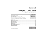
Figure 4.0
Operating Procedures
Step-by-Step Operating Procedures Flow Diagram
7
Model CT-3500
Operating Procedures
5.0 Operating Procedures
(See Figure 3.0. Step-by-Step Procedures for
Operating the CT-3500.)
with STARTUP MENU(see next display
menu).
START-UP MENU
5.1
Introduction
Before first-time operation of the CT3500, Step-by-Step Operating Procedures
Flow Diagram (Figure 3) should be
reviewed. This figure shows the logicflow branching of multiple test options.
CT-3500 operation is simple, requiring
little more than selecting choices from
display menus and responding to the
displayed prompts. (Experienced
operators may use Figure 3.0 as a handy
operating reference.)
5.2
START-UP
MENU
1. RUN
TEST
05/15/01
2. SETUP
10:28:03
3. CABLE TEST
b. Press number 2 (SETUP) to enter
identification data. (See Figures 3.0 for
reference to the desired test path.) Go to
the next step (c.). If identification data are
already entered, then press number 1 key
(RUN TEST) and go to section 5.5.
Precautions
c. When SETUP is chosen, the SET-UP
MENU (below) displays. Go to next step.
WARNING
Make sure that the CT-3500 is fully
grounded before connecting it to any
presumed-to-be deenergized breaker.
Also, disconnect main lines to the breaker
and ground main links to breaker contacts
before making test hookups. Failure to
heed this warning can result in death,
personal injury, and/or damage to
equipment.
5.3
SET-UP MENU
1. ENTER ID
2. REVIEW SHOT
3. RESTORE SHOT
4. NEXT PAGE
NOTICE
The next steps require entering of
identification data, which involves
pressing keys to enter character for
the prompted input. The keypad
(Figure 1, item 7) is marked like a
telephone keypad, but is used
differently, as explained here; As
an example, consider alpha/number
key 2/ABC:
Preliminary Procedure
a. Turn on CT-3500 power; press “1” on
the rocker switch (item 4 in Figure 1).
b. Observe that after configuration data
displays briefly, the START-UP MENU
displays (selections for “1. RUN TEST,”
“2. SETUP,” and “3. CABLE TEST”).
2
ABC
5.4
Identification Setup Procedure
If documented test records are to be kept
and full test reports are to be printed, then
the IDENTIFICATION SETUP must be
entered before any other timing-related
procedure.
Press the key once to select
number “2,” press a second time to
select letter “A,” press a third time
to select letter “B,” and press a
fourth time to select letter “C.”
Pressing the key a fifth time
returns to display number 2, after
which, additional key presses
a. START-UP MENU: Observe that the
Start-Up menu is the initial display at
power-up and boot; all procedures start
8
Model CT-3500
Operating Procedures
repeat the A, B, C cycle.
Selections from the rest of the
alpha/numeric keys are done the
same. The 1 and 0 (zero) keys
have no alpha functions.
When a character is entered and
appears in the display at the
cursor position, the cursor is
advanced to the next position by
pressing the ∧ key or backedspaced by pressing the ∨ key. To
delete a character, press CLEAR.
When all character entries are
selected, press ENTER key to
load the identity data in storage
registers, and go to the next
prompt display.
MANUFACTURER:
h. Key select characters of the
MANUFACTURER name, then press
ENTER key. The MODEL prompt
appears:
MODEL:
i. Key select characters of the MODEL
name, then press ENTER key. The
SERIAL prompt appears:
SERIAL NUMBER:
d. On the Set-Up Menu, press number 1
(ENTER ID); the prompt COMPANY
displays (see below).
j. Key select characters of the SERIAL
NUMBER, then press ENTER. The KVA
RATING prompt appears:
COMPANY:
e. Key select characters of the utility
COMPANY name, then press ENTER.
The STATION prompt appears:
KVA RATING:
STATION:
k. Key select characters of the KVA
RATING, then press ENTER. The
OPERATOR prompt appears:
f. Key select characters of the STATION
name, then press ENTER. The CIRCUIT
prompt appears:
OPERATOR:
CIRCUIT:
l. Key select characters of OPERATOR
name, then press ENTER key. The
display returns to the START-UP MENU.
g. Key select characters of the CIRCUIT
name, then press ENTER. The
MANUFACTURER prompt appears:
NOTE
Identification data should be entered for
each breaker that is tested
9
Model CT-3500
Operating Procedures
5.5
Run Test Procedure
Time a breaker by performing the step-bystep sequence that follows. The Run-Test
Procedure assumes that setups have been
loaded (typically, a one-time test can be
run without such documentation).
CLOSE, or CLOSE-OPEN), in this case,
an OPEN.
When the breaker has operated, the
selected test (also called a “shot”), a date
and time “stamp” displays (see below),
which will link this timing record (if it is
saved) for all future recall references.
The CT-3500 will stamp the date and time
of each test on the record. The user needs
to verify the time and date (displayed at
the top left corner of the CT-3500 LCD)
before test
OPEN SHOT
07/12/01
15:25:48
d. When date and time of test is noted,
press ENTER to advance to the next
display (timing results of each phase).
Timing results display in both
milliseconds (mS) and decimal parts of a
cycle (CY).
START-UP MENU
1. RUN TEST
2. SETUP
3. CABLE TEST
05/15/01
10:28:03
OPEN
A
B
C
a. Begin the RUN-TEST procedure by
pressing key #1 on the START-UP MENU
(see last illustration). The SELECT TEST
TYPE menu then displays (see below):
SELECT TEST TYPE
1. OPEN
2. CLOSE
3. OPEN-CLOSE
4. CLOSE-OPEN
(mS / CYCLES)
34.90mS 2.09CY
30.39mS 1.81CY
33.70mS 2.02CY
e. After the initial test time is displayed
and observed, press ENTER key to
advance to the next display contact bounce
time
OPEN BOUNCE TIME
A: 0.00mS 0.00CY
B 0.00mS 0.00CY
C 0.00mS 0.00CY
b. Press the key for the breaker test to be
timed (listed on the Menu above). An
OPERATE BREAKER prompt will
display. In the example below, the OPEN
test was selected. The test procedure is
shown in steps below.
f. When the three-phase bounce time
results display, press ENTER key to
advance to next display. If the timing was
a single stroke, the next display will
prompt: PRINT TEST RESULTS?
TEST: OPEN
OPEN BREAKER NOW…
c. The above display prompts the
operator to activate the breaker for the
selected test (OPEN, CLOSE, OPEN-
PRINT RESULTS?
1. YES
2. NO
10
Model CT-3500
Operating Procedures
g. Press key 1 (YES, print test results) if
a timer results paper record is to be
printed, in which case the printing
advisory (below) displays. If YES, go to
the next step.
h. Press key #2 (NO, don’t print the test
results) to bypass the printing phase, in
which case the SAVE THIS SHOT?
prompt displays. If NO, go to step n.
j. Press key #1 (YES) to save the timing
shot in memory for future reference, in
which case the save is confirmed by the
next display (see below). If Key #2 (NO)
is pressed, the run-test timing is completed
and the display returns to the START-UP
menu.
SHOT NUMBER 01
HAS BEEN SAVED!
PLEASE WAIT
PRINTING…
i. While the printer is printing no other
action is required of the operator until
printing is complete, after which the
SAVE THIS SHOT? prompt displays (see
below):
k. When the shot number displays (the
shot is automatically numbered by the CT3500), press ENTER: the display returns
to the START-UP MENU. This step
completes the RUN TEST procedure.
SAVE THIS SHOT?
1. YES
2. NO
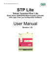
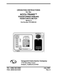
Figure 5.0
A typical CT-3500 OPEN Test print out
11
Model CT-3500
Operating Procedures
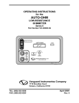
Figure 6.0
A typical CT-3500 CLOSE-OPEN Test print out
a. Press ENTER key to advance to the next
Note:
display (i.e., second-stroke bounce time).
If the timing shot was a dual operation (e.g.,
CLOSE-OPEN), the display will display the
CLOSE BOUNCE TIME
test results first operation (in this case
A 32.10mS 1.92CY
CLOSE) then the second operation (OPEN)
B 00.90mS 0.05CY
and finally time between the two operation
(contact LIVE time).
C 14.80mS 0.88CY
A typical CLOSE-OPEN operation the first
test results (CLOSE) is shown as follows:
b. Press ENTER key to advance to the next
display (i.e., second-stroke bounce time).
CLOSE (mS / CYCLEs)
A 171.80mS 10.30CY
B 174.20mS 10.45CY
C 172.00mS 10.32CY
OPEN (mS / CYCLES)
A 1632.80mS 97.96CY
B 1628.50mS 87.71CY
C 1631.70mS 97.90CY
12
Model CT-3500
Operating Procedures
c. Press ENTER key to advance to the next
display (i.e., second-stroke bounce time).
REVIEW TEST
1. DISPLAY TEST DATA
2. PRINT TEST DATA
OPEN BOUNCE TIME
A
00.00mS
0.00CY
B
04.20mS
0.25CY
C
00.40mS
0.02CY
b. Press key 1 to display shot identification
and key-in number of shot to be reviewed
(default is last timing shot). The display
will show the shot record number (just
selected), the type of shot (OPEN, CLOSE,
OPEN-CLOSE, or CLOSE-OPEN), and the
date and time of the selected shot (shown in
the second display below)—go to the next
step.
d. Press ENTER key to advance to the next
three-phase timing result display (i.e.,
CONTACT LIVE TIME—see below).
CONTACT LIVE TIME
A 1460.90mS
87.65CY
B 1454.30mS
87.25CY
C 1459.70mS 87.58CY
SHOT 01
OPEN SHOT
05/15/01 10:28:03
5.6
Review Shot Procedure
This procedure describes steps to review a
test record residing in CT-3500 working
memory. The user can view the record on
the LCD display or from a thermal printout.
Press key # 2 (PRINT DATA) to print out
all the timing data on the selected shot
record, during which the advisory DISPLAY
IS shown below.
NOTE
To review a test record stored in Flash
EEPROM, the user must first restore test
record from Flash EEPROM to working
memory (see paragraph 5.7)
PRINTING REPORT
PLEASE WAIT…
The Restore Recording Procedure steps
begin at the Set-Up Menu, shown below:
After printing, the display returns to the
START-UP MENU, thus ending the Review
Shot procedure).
SET-UP MENU
c. When the shot record of interest displays
(see b.), press ENTER to begin the timing
review sequence (virtually the same display
sequence that displayed during the original
timing shot—refer to section 5.5), after
which the display returns to the START-UP
Menu. This ends the Review Data
procedure.
1. ENTER ID
2. REVIEW SHOT
3. RESTORE SHOT
4. NEXT PAGE
a. Press key #2 (REVIEW SHOT) to begin
the Review-Shot procedure. The following
menu displays:
13
Model CT-3500
Operating Procedures
5.7
Restore Shot Procedure
This procedure allows the user to restore a
test record from the CT-3500 Flash
EEPROM to working memory. The user
then can review the test record using the
REVIEW RECORD command (5.6).
RESTORE SHOT
NUMBER: 1
d. Key in the number of the shot to be
restored and press ENTER: “Shot Restored”
displays (see below) after which the
REVIEW DATA sequence begins (go back
to step b of section 5.6 to continue the
RESTORE SHOT procedure to conclusion).
The Restore Recording Procedure steps
begin at the Set-Up Menu, shown below:
SET-UP MENU
1. ENTER ID
2. REVIEW SHOT
3. RESTORE SHOT
4. NEXT PAGE
SHOT RESTORED!
e. The SCROLL TO SELECT (option 2
back in step c) an instructional prompt
displays (see below):
a. Press key #3 (RESTORE SHOT) to
begin the Restore-Shot procedure. The
following menu displays:
SHOT DIRECTORY
“UP” TO SCROLL FWD
“DWN” TO SCROLL RVS
1. RESTORE SHOT
2. DIRECTORY
3. ERASE SHOT
4. (RE)SAVE SHOT
Use the UP (? ) and DOWN (? ) keys to
scroll through the saved shot records until
the shot record of interest displays, and then
press ENTER. Then the REVIEW DATA
sequence begins (go back to step b of
section 5.6 and continue the RESTORE
SHOT procedure to conclusion, after which
the START-UP MENU displays).
b. Press key # 1 to select the Restore Shot
function: this displays the RESTORE SHOT
menu (shown below).
RESTORE SHOT
1. ENTER SHOT NUMBER
2. SCROLL TO SELECT
#01 08/15/01 10:28:03
OPEN SHOT
c. If the number of the shot to be restored
is known, press key number 1(ENTER
SHOT NUMBER) and go to next step; if the
number of the shot to be restored is not
known, press key number 2 (SCROLL TO
SELECT) and skip forward to step e.
This ends the RESTORE SHOT procedure.
14
Model CT-3500
Operating Procedures
5.8
Print Test-Record Directory
Printing the test record directory begins with
the Set-Up Menu shown below (the same
display from which the Review Records
steps began):
b. Press key # 2 to select the Directory
function: this displays the DIRECTORY
menu (shown below).
PRINT DIRECTORY
1. FULL DIRECTORY
2. SHORT DIRECTORY
SET-UP MENU
1. ENTER ID
2. REVIEW SHOT
3. RESTORE SHOT
4. NEXT PAGE
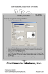
c. Press key #1 to print a directory of all
shots stored in the CT-3500 memory. Press
key #2 to print the directory of the last 10
timing shots stored in the CT-3500 memory.
A typical CT-3500 directory print out is
shown in figure 7.0.
a. Press key #3 (RESTORE SHOT) to
begin the Restore-Shot procedure. The
following menu displays:
1. RESTORE SHOT
2. DIRECTORY
3. ERASE SHOT
4. (RE)SAVE SHOT
Figure 7.0
Typical CT-3500 Shot Directory
15
Model CT-3500
Operating Procedures
5.9
Computer Interface Procedure
The CT-3500 can store up to 128 timing
records in the FLASH EEPROM. These test
reports can be transferred through the RS232C port. A window software package
provided with the CT-3500 allows the user
to transfer test report to the IBM PC.
5.10 Set Date and Time
The date and time setting begins at the SetUp Menu, shown below:
a. Begin at the START-UP MENU: Press
key #2 (SETUP) to display the SET-UP
MENU shown below:
SET-UP MENU
1. ENTER ID
2. REVIEW SHOT
3. RESTORE SHOT
4. NEXT PAGE
Use the following steps to put the CT-3500
under computer interface mode:
a. Accordingly, Press key #2 (SETUP) on
the Start-Up Menu, which will produce the
SET-UP MENU (shown below):
SET-UP MENU
b. Press key #4 (NEXT PAGE) to display
the menu shown below:
1. ENTER ID
2. REVIEW SHOT
3. RESTORE SHOT
4. NEXT PAGE
1. COMPUTER CONTROL
2. SET TIME
3. SET 50/60 Hz
b. Press key # 4 NEXT PAGE) to display
the following options menu:
c. Press key # 2 (SET TIME) to display the
prompt to enter the present date and time
(shown below):
1. COMPUTER CONTROL
2. SET TIME
3. SET 50/60 Hz
ENTER
MM-DD-YY HH:MM:SS
c. Press Key # 1 (COMPUTER
CONTROL) to control the CT-3500 from a
remote IBM-compatible PC. The computer
interface (ITF) mode advisory displays
(shown below): go to the next step
NOTE
In the above prompt: MM = month,
DD = day, YY = year, and HH = hour,
MM = minute, SS=seconds.
d. Set the date (month, day, year) with six
key presses for the above prompt; Set the
time (hour, minute, second) with six key
presses. When date and time are set, the
screen will return to the START-UP MENU.
This completes set date/time procedure.
COMPUTER ITF MODE
d. From this point on (for as long as this
screen displays, the CT-3500 is controlled
by the PC. To end the Computer Interface
mode, press the STOP key, at which time
the display will return to the START-UP
MENU (section 5.4).
5.11 Set 50/60 Hz Procedure
The test result of the CT-3500 display in
millisecond and cycles. The user can select
either 50Hz or 60Hz cycle mode on the test
results.
16
Model CT-3500
Operating Procedures
Use the following steps to set 50/60Hz
mode:
a. Beginning at the START-UP MENU,
press key #2 (SETUP) to display the SETUP MENU shown below:
hookups.) When the test hookup is made to
the breaker, run a Cable Test to make sure
all 3 test lead clips are properly connected
(contact clips are across mating contacts).
Begin with the Start-Up Menu (below):
SET-UP MENU
START-UP MENU
1. RUN TEST
2. SETUP
3. CABLE TEST
1. ENTER ID
2. REVIEW SHOT
3. RESTORE SHOT
4. NEXT PAGE
05/15/01
10:28:03
a. After test hookup to the breaker, open
the breaker and press key #3 (Cable Test).
The display below shows the line status of
each of three sets of contacts (all three
should show open).
b. Press key #4 (NEXT PAGE) to display
the menu shown below:
1. COMPUTER CONTROL
2. SET TIME
3. SET 50/60 Hz
CABLE TEST
CH A
CH B
CH C
OPEN
OPEN
OPEN
(ANY KEY TO EXIT)
c. Press key #3 (SET 50/60 Hz) to select
the Menu for power-line frequency that the
breaker controls. This displays the Set Line
Frequency menu shown below:
b. Press ENTER key to return to Start-Up
Menu.
SET LINE FREQUENCY
1. 60 Hz
2. 50 Hz
c. Set the breaker contacts to the closed
condition and again press key #3 (cable test)
on the Start-Up Menu. The display below
shows the line status of each of three sets of
contacts (all three should show close).
d. Press the key for the frequency of power
that the breaker controls when it’s in service
(i.e., on line). When either the #1 or #2 key
is pressed, the display returns to the Start-Up
Menu.
This ends the Set Line Frequency procedure.
CABLE TEST
CH A
CH B
CH C
CLOSE
CLOSE CLOSE
(ANY KEY TO EXIT)
5.12 Cable Test Procedure
The purpose of the Cable Test is to quickly
check the test leads and breaker contacts for
continuity at each of the 3 phase contacts.
(For example, a close test should begin with
all contacts open; conversely an open test
should begin with all three contacts closed—
the closed condition also checks continuity
of the test leads for opens or erroneous
d. Press ENTER to return to Start-Up
Menu.
This completes the Cable test procedure.
This completes all operating procedures
17
Model CT-3500
Operating Procedures
Model CT-3500
Operating Procedures
APPENDIX A
CT-3500 Troubleshooting Guide
Item Symptom
1
CT-3500 will not
start timing.
2
CT-3500 displays
“Detect Standing
Voltage”.
3
Timing channels is
not working
correctly.
Possible Problem
1. No trigger voltage
detected.
2. Broken trigger lead.
1.There is standing voltage
across trigger input lead.
The CT-3500 expects a
voltage only when the
circuit breaker coil is
energized.
Solution
1.Check trigger cable connection
to Trip and Close coil.
2. Inspect trigger cable cables.
1. Check trigger-cable
connection to trip and close coil.
2. If there is standing voltage
across coil, check for lamp
(indicator) circuit.
1. Bad contact cable
connection to breaker.
2. Missing common
connection on the breaker
bushing.
1 Check contact cable
connection to breaker.
2. Inspect contact leads.
3. Make sure the common side
(black lead) of contact bushing is
tied to ground.
1710 Grevillea Court, Ontario, CA 91761, USA
Phone: 909-923-9390
Fax: 909-923-9391
Website: http//www.vanguard-instruments.com