1
8 Pin Assignment
8.1 IP Connectors
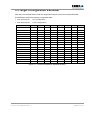
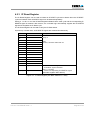
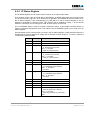
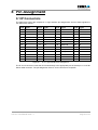
The table below shows the complete IP J1 logic interface pin assignments. Some of these signals are
not used on the TCP211.
Pin # Signal
Pin # Signal
Pin # Signal
Pin # Signal
1
GND
2
CLK
26
GND
27
+5V
3
Reset#
4
D0
28
R/W#
29
IDSel#
5
D1
6
D2
30
DMAReq0#
31
MemSel#
7
D3
8
D4
32
DMAReq1#
33
IntSel#
9
D5
10
D6
34
DMAck#
35
IOSel#
11
D7
12
D8
36
Reserved
37
A1
13
D9
14
D10
38
DMAEnd#
39
A2
15
D11
16
D12
40
Error#
41
A3
17
D13
18
D14
42
IntReq0#
43
A4
19
D15
20
BS0#
44
IntReq1#
45
A5
21
BS1#
22
-12V
46
Strobe#
47
A6
23
+12V
24
+5V
48
ACK#
49
Reserved
25
GND
50
GND
Figure 8-1 : IP J1 Logic Interface Pin Assignment
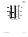
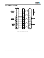
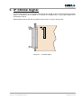
The IP J2 I/O connector routes the IP I/O lines directly to the appropriate pins of the 50 pin 0.1 inch flat
ribbon cable connector. The pin assignment of the IP J2 I/O connector is IP specific.
TCP211 User Manual Issue 1.1
Page 32 of 32