1
RHF050KHEA
RHF100KHEA
ERV Plus (ERV with DX-COIL)
user & installation manual
imagine the possibilities
Thank you for purchasing this Samsung product.
To receive more complete service, please
register your product at
www.samsung.com/register
E S F I P D DB98-32885A(1)
RHF050KHEA_IB,IM_E_32885-1.indd 53
2010-12-15 오전 11:27:14
AF-
Features of your new product
Energy Recovery Ventilation
The product helps save energy and drive down operation costs of heaters and coolers by recycling thermal energy
(energy load) efficiently.
Interlocked operation with DVM
Controls of interlocked operation for energy saving, One remote controller can be used with air conditioners.
Mounted for DX-coil unit for outdoor air treatment
This improves the dry and cooling effect in the summer and humidifying effect in the winter.
Humidity Control
Fresh air conditions are guaranteed by recovering moisture in winter while exhausting it in summer.
The high efficiency Humidifier element can be mounted.(Optional product)
Low Noise and Low Power
With highly efficient motor and optimized system design, operation noise and electric consumption is minimized.
The high efficiency filter
This protects the heat exchange element and cleans the polluted outdoor air before it enters the indoor room.
Operation at Cold Area
Optimized automatic ventilation operation is conducted to prevent condensation and air volume reduction.
Clean-UP operation
Prevent the odor and dust of other places such as bathroom and kitchen from entering inside by making supply air greater
than the exhaustion air. (You can reverse this procedure to make the exhaustion air bigger than the supply air.)
How to use this unit
This unit should be used with air conditioners. Air conditioning is impossible only by this unit, because this unit does not
have temperature control function. (It’s capacity is too small in order to control the room temperature to the whole)
And should be operated in combination with standard indoor units. (Interlocked operation) Independent operation is
possible, however, temperature setting by remote controller is impossible. In this ON/OFF operation by thermostat depends
on factory setting, however, this value is changeable by installation/service mode on site. Model selection should be done
not by cooling capacity but by ventilating air flow rate.
2
RHF050KHEA_IB,IM_E_32885-1.indd 2
2010-12-15 오전 11:26:46
Contents
USING PARTS
ENGLISH
Safety precautions ................................................................................................................................................................................................................................. 4
Checking before use . ........................................................................................................................................................................................................................... 8
Checking the name of the parts .................................................................................................................................................................................................. 10
Basic operation . ................................................................................................................................................................................................................................... 16
Cleaning and maintaining the unit ............................................................................................................................................................................................ 19
Maintaining your product . ............................................................................................................................................................................................................. 23
Troubleshooting .................................................................................................................................................................................................................................. 24
INSTALLATION PARTS
Safety precautions .............................................................................................................................................................................................................................. 26
Accessories . ........................................................................................................................................................................................................................................... 28
Selecting the installation location . ............................................................................................................................................................................................. 28
Indoor unit installation ..................................................................................................................................................................................................................... 30
Purging the unit . ................................................................................................................................................................................................................................. 31
Connecting the refrigerant pipe .................................................................................................................................................................................................. 32
Cutting/flaring the pipe ................................................................................................................................................................................................................... 33
Performing leak test & insulation ................................................................................................................................................................................................ 34
Drain pipe and drain installation ................................................................................................................................................................................................. 36
Drain pipe and drain hose installation ...................................................................................................................................................................................... 37
Duct connection . ................................................................................................................................................................................................................................ 38
Wiring work ........................................................................................................................................................................................................................................... 39
Indoor unit setting . ............................................................................................................................................................................................................................ 42
Additional functions .......................................................................................................................................................................................................................... 43
Trial operation ...................................................................................................................................................................................................................................... 45
Final checks and user tips . .............................................................................................................................................................................................................. 46
Troubleshooting .................................................................................................................................................................................................................................. 47
Wired Remote Controller Installation/Service Mode ......................................................................................................................................................... 48
This product has been determined to be in compliance with the Low Voltage Directive (2006/95/EC), and the Electromagnetic
Compatibility Directive (2004/108/EEC) of the European Union.
Correct Disposal of This Product
(Waste Electrical & Electronic Equipment)
(Applicable in the European Union and other European countries with separate collection systems)
This marking shown on the product or its literature, indicates that it should not be disposed with other household wastes at the end of its
working life. To prevent possible harm to the environment or human health from uncontrolled waste disposal, please separate this from
other types of wastes and recycle it responsibly to promote the sustainable reuse of material resources.
Household users should contact either the retailer where they purchased this product, or their local government office, for details of where
and how they can take this item for environmentally safe recycling.
Business users should contact their supplier and check the terms and conditions of the purchase contract.
This product should not be mixed with other commercial wastes for disposal.
3
RHF050KHEA_IB,IM_E_32885-1.indd 3
2010-12-15 오전 11:26:46
USING PARTS
Safety precautions
Before using your new product, please read this manual thoroughly to ensure that you know how to safely and efficiently
operate the extensive features and functions of your new appliance.
Because the following operating instructions cover various models, the characteristics of your product may differ slightly from
those described in this manual. If you have any questions, call your nearest contact center or find help and information online
at www.samsung.com.
Important safety symbols and precautions:
WARNING
Hazards or unsafe practices that may result in severe personal injury or death.
CAUTION
Hazards or unsafe practices that may result in minor personal injury or property damage.
Follow directions.
Do NOT attempt.
Make sure the machine is grounded to prevent electric shock.
Unplug the power plug from the wall socket.
Do NOT disassemble.
FOR INSTALLATION
WARNING
Use the power line with the power specifications of the product or higher and use the power line for this appliance only.
In addition, do not use an extension line.
Extending the power line may result in electric shock or fire.
Do not use an electric transformer. It may result in electric shock or fire.
If the voltage/frequency/rated current condition is different, it may cause fire.
The installation of this appliance must be performed by a qualified technician or service company.
Failing to do so may result in electric shock, fire, explosion, problems with the product, or injury.
Install a switch and circuit breaker dedicated to the product.
Failing to do so may result in electric shock or fire.
Fix the outdoor unit firmly so that the electric part of the outdoor unit is not exposed.
Failing to do so may result in electric shock or fire.
Do not install this appliance near a heater, inflammable material. Do not install this appliance in a humid, oily or dusty
location, in a location exposed to direct sunlight and water (rain drops). Do not install this appliance in a location where
gas may leak.
This may result in electric shock or fire.
Never install the outdoor unit in a location such as on a high external wall where it could fall.
If the outdoor unit falls, it may result in injury, death or property damage.
This appliance must be properly grounded. Do not ground the appliance to a gas pipe, plastic water pipe, or telephone
line.
Failure to do so may result in electric shock, fire, an explosion, or other problems with the product. Never plug the power cord into a socket that is not grounded correctly and make sure that it is in accordance with local and
national codes.
4
RHF050KHEA_IB,IM_E_32885-1.indd 4
2010-12-15 오전 11:26:47
FOR INSTALLATION
CAUTION
ENGLISH
Install your appliance on a level and hard floor that can support its weight.
Failing to do so may result in abnormal vibrations, noise, or problems with the product.
Install the draining hose properly so that water is drained correctly.
Failing to do so may result in water overflowing and property damage.
When installing the outdoor unit, make sure to connect the draining hose so that draining is performed correctly.
The water generated during the heating operation by the outdoor unit may overflow and result in property damage.
In particular, in winter, if a block of ice falls, it may result in injury, death or property damage.
Do not let the discharged air go back to the indoor through its air suction hole. It can contaminate indoor air.
Do not connect the electric heater to the product.
Hang down a blockage for bird in front of outdoor air suction duct. If something such as bird's nest blocks the
air suction duct, it may result in oxygen shortage in indoors.
FOR POWER SUPPLY
WARNING
When the circuit breaker is damaged, contact your nearest service center.
Do not pull or excessively bend the power line. Do not twist or tie the power line. Do not hook the power line over a
metal object, place a heavy object on the power line, insert the power line between objects, or push the power line into
the space behind the appliance.
This may result in electric shock or fire.
FOR POWER SUPPLY
CAUTION
When not using the product for a long period of time or during a thunder/lightning storm, cut the power at the circuit
breaker.
Failing to do so may result in electric shock or fire.
FOR USING
WARNING
If the appliance is flooded, please contact your nearest service center.
Failing to do so may result in electric shock or fire.
If the appliance generates a strange noise, a burning smell or smoke, unplug the power plug immediately and contact
your nearest service center.
Failing to do so may result in electric shock or fire.
In the event of a gas leak (such as LNG, LPG or Liquefied natural gas, Liquefied petroleum gas, etc.), ventilate immediately
without touching the power line.
Do not touch the appliance or power line.
Do not use a ventilating fan.
A spark may result in an explosion or fire.
To reinstall the product, please contact your nearest service center.
Failing to do so may result in problems with the product, water leakage, electric shock, or fire.
A delivery service for the product is not provided. If you reinstall the product in another location, additional construction
expenses and an installation fee will be charged.
Especially, when you wish to install the product in an unusual location such as in an industrial area or near the seaside where it is
exposed to the salt in the air, please contact your nearest service center.
5
RHF050KHEA_IB,IM_E_32885-1.indd 5
2010-12-15 오전 11:26:47
Safety precautions
FOR USING
WARNING
Do not touch the circuit breaker with wet hands.
This may result in electric shock.
Do not strike or pull the product with excessive force.
This may result in fire, injury, or problems with the product.
Do not place an object near the outdoor unit that allows children to climb onto the machine.
This may result in children seriously injuring themselves.
Do not turn the product off with the circuit breaker while it is operating.
Turning the product off and then on again with the circuit breaker may cause a spark and result in electric shock or fire. After unpacking the product, keep all packaging materials well out of the reach of children, as packaging materials can
be dangerous to children.
If a child places a bag over its head, it may result in suffocation.
Do not insert your fingers or foreign substances into the air inlet/outlet of the product.
Take special care that children do not injure themselves by inserting their fingers into the product.
Do not use the product as a ventilator for a burner.
If you use a burner with gas or gasoline, you need to have separate ventilation system for the combustible apparatus.
If any foreign substance such as water has entered the appliance, cut the power by unplugging the power plug and
turning the circuit breaker off and then contact your nearest service center.
Failing to do so may result in electric shock or fire.
Do not attempt to repair, disassemble, or modify the appliance yourself.
Do not use any fuse (such as cooper, steel wire, etc.)other than the standard fuse.
Failing to do so may result in electric shock, fire, problems with the product, or injury.
FOR USING
CAUTION
Do not place objects or devices under the indoor unit.
Water dripping from the indoor unit may result in fire or property damage.
Check that the installation frame of the outdoor unit is not broken at least once a year.
Failing to do so may result in injury, death or property damage.
Max current is measured according to IEC standard for safety and current is measured according to ISO standard for
energy efficiency.
6
RHF050KHEA_IB,IM_E_32885-1.indd 6
2010-12-15 오전 11:26:47
FOR USING
CAUTION
ENGLISH
Do not stand on top of the appliance or place objects (such as laundry, lighted candles, lighted cigarettes, dishes,
chemicals, metal objects, etc.) on the appliance.
This may result in electric shock, fire, problems with the product, or injury.
Do not operate the appliance with wet hands.
This may result in electric shock.
Do not spray volatile material such as insecticide onto the surface of the appliance.
As well as being harmful to humans, it may also result in electric shock, fire or problems with the product.
Do not drink the water from the product.
The water may be harmful to humans.
Do not apply a strong impact to the remote controller and do not disassemble the remote controller.
Do not touch the pipes connected with the product.
This may result in burns or injury.
Do not use this product to preserve precision equipment, food, animals, plants or cosmetics, or for any other unusual
purposes.
This may result in property damage.
Avoid directly exposing humans, animals or plants from the air flow from the product for long periods of time.
This may result in harm to humans, animals or plants.
This appliance is not intended for use by persons (including children) with reduced physical, sensory or mental
capabilities, or lack of experience and knowledge, unless they have been given supervision or instruction concerning use
of the appliance by a person responsible for their safety. Children should be supervised to ensure that they do not play
with the appliance.
FOR CLEANING
WARNING
Do not clean the appliance by spraying water directly onto it. Do not use benzene, thinner or alcohol to clean the
appliance.
This may result in discoloration, deformation, damage, electric shock or fire.
Before cleaning or performing maintenance, unplug the product from the wall socket and wait until the fan stops.
Failing to do so may result in electric shock or fire.
FOR CLEANING
CAUTION
Take care when cleaning the surface of the heat exchanger of the outdoor unit since it has sharp edges.
To avoid cutting your fingers, wear thick cotton gloves when cleaning it.
Do not clean the inside of the product by yourself.
For cleaning inside the appliance, contact your nearest service center.
When cleaning the internal filter, refer to the descriptions in the ‘Cleaning and maintaining the unit' section.
Failure to do may result in damage, electric shock or fire.
7
RHF050KHEA_IB,IM_E_32885-1.indd 7
2010-12-15 오전 11:26:47
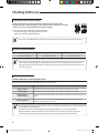
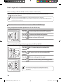
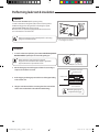
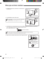
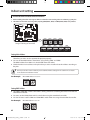
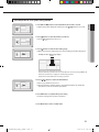
Checking before use
Checking Up the Sub Power Supply
The sub power supply is a device to prevent electric leakage due to the over current.
Install the sub power supply separately near the ventilator and turn it off when you clean the
ventilator or you do not use the ventilator for a long period of time.
Turn on the sub power supply which is installed separately.
- The sub power supply is not supplied with the ventilator.
Purchase the sub power supply individually.
•If the circuit breaker (MCCB, ELB) is installed, the sub power supply does not need to be installed mandatorily.
Install & Operation Ranges
Install condition
Outdoor air condition
Indoor air condition
0~40°C, 80%RH below
-15~40°C, 80%RH below
0~40°C, 80%RH below
•If the ventilator is operated under the condition other than are indicated, it may not operate due to the protective
device in the ventilator. Especially, if outside temperature is under -15°C, the ventilator does not operate at all.
•Do not operate the ventilator when typhoon comes. Water may get in the room through the ventilator due to the
rain and heavy winds.
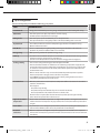
Maintaining your product
Internal protections via the unit control system
This internal protection operates if an internal fault occurs in the product.
Type
Description
Against cold air
The internal fan will be off to against cold air when the heat pump is heating.
De-frost cycle
The internal fan will be off to against cold air when the heat pump is heating.
Anti-protection of
internal battery
The compressor will be off to protect internal battery when the product operates in Cool
mode.
Protect compressor
The product does not start operating immediately to protect the compressor of the
outdoor unit after it has been started.
•If the heat pump is operating in Heat mode, De-ice cycle is actuated to remove frost from an outdoor unit that may
have deposited at low temperatures.
The internal fan is switched off automatically and restarted only after the de-ice cycle is completed.
When the outdoor air suction temperature becomes lower than -10°C, the unit is changed to intermittent
operation to prevent freezing of the heat exchanger element and dew condensation within the unit.
8
RHF050KHEA_IB,IM_E_32885-1.indd 8
2010-12-15 오전 11:26:47
Tips on using product
Here are some tips that you would follow when using your product.
ENGLISH
TOPIC
RECOMMENDATION
Heat-EX Mode
•Energy loss is minimized by recovering energy exhausted when indoor heating and cooling
Quiet Mode
•This allows you to have quiet sleep and fresh air while sleeping.
•The ERV operation lamp will also be less bright.
Outing Mode
•This allows you to operate the ERV while you are away from home.
•If the operational status is changed by another controller, the Outing mode is canceled.
By-Pass Mode
•The ventilation method is used when temperature gap of indoor and outdoor is not big.
•Outdoor air flows into indoor.
Auto Mode
•The air is automatically changed depending on the degree of pollution in the indoor air.
(Available only when the additional CO2 sensor is installed)
Energy saving
•Make operating condition for optimized energy saving.
Clean up
•Prevent the odor and dust of other places such as bathroom and kitchen from entering inside by
making the supply air greater than the exhaustion air.
(You can reverse this procedure to make the exhaustion air bigger than the supply air.)
Cooling / Heating
•You can have cooling and heating operation through the DX-COIL.
•This unit should be used with air conditioners. Air conditioning is impossible only by this unit,
because this unit does not have temperature control function. (It’s capacity is too small in order
to control the room temperature to the whole) and should be operated in combination with
standard indoor units.
•When a remote controller is only connected to the ERV, independent operation is possible.
However, temperature setting by remote controller is not possible.
•In this ON/OFF operation by thermostat depends on factory setting. However, this value is
changeable by installation/service mode on site.
Frost & De-frost
•When the product runs in Heat mode, due to temperature difference between the unit and the
outside air, frost will form.
If this happens:
- The product stops heating.
-The product will operate automatically in De-ice mode for 10 minutes.
- The steam produced on the outdoor unit in De-ice mode is safe.
No intervention is required; after about 10 minutes, the product operates again normally.
The unit will not operate when it starts to de-ice.
High indoor/outdoor
temperatures
•If both indoor and outdoor temperatures are high and the product is running in Heat mode, the
outdoor unit’s fan and compressor may stop at times. This is normal; wait until the product turns
on again.
Power failure
•If a power failure occurs during the operation of the product, the operating immediately stops
and unit will be off. When power returns, the product will run automatically.
Protection
mechanism
•After the compressor has stopped or the power supply has been switched on, the compressor
will not run for 3 minutes for its protection therefore cool/warm air does not come out of the unit
immediately.
9
RHF050KHEA_IB,IM_E_32885-1.indd 9
2010-12-15 오전 11:26:48
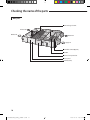
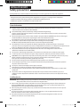
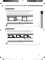
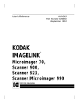
Checking the name of the parts
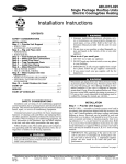
Main parts
Heat exchange element
Exhaust Air
OutdoorAir
Return Air
Supply Air
Humidifier element(Option)
DX-COIL
Electrical component box
Access panel
Air filter(inside)
10
RHF050KHEA_IB,IM_E_32885-1.indd 10
2010-12-15 오전 11:26:48
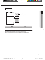
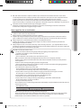
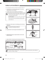
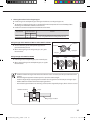
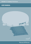
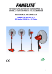
Inspection hole
ENGLISH
A
Access for inspection/
maintenance
A
Model
'A' (mm)
RHF050KHEA
450 x 450
RHF100KHEA
550 x 550
There is access for inspection/maintenance for cleaning the air filter and the heat exchanger element.
Lack of installation and maintenance spaces may cause injury or malfunction.
There is also access for inspection/maintenance of the DX-coil and humidifier element.
11
RHF050KHEA_IB,IM_E_32885-1.indd 11
2010-12-15 오전 11:26:48
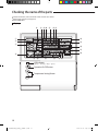
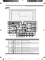
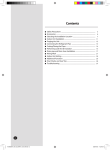
Checking the name of the parts
For detailed instruction, refer to the wired remote controller user manual.
Wired remote controller (not supplied)
Model: MWR-WE10
Display
④
⑤ ⑨⑩
⑪
⑫⑬
⑭
①
②
⑮
③
⑯
⑰
⑱
⑥
⑦
⑧
⑳ ⑲
LED Indicator
(Green : Normal / Red : Error)
Operation On/Off button
Temperature Setting Button
12
RHF050KHEA_IB,IM_E_32885-1.indd 12
2010-12-15 오전 11:26:48
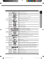
Product
Related
Information
Schedule
related
information
Ventilator
(ERV)
related
information
Commom
function
related
information
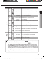
Indication
Function
ENGLISH
Classification
①
Displays System operation
②
Displays Quiet/Sleep operation
③
Displays Indoor temperature/Set temperature
④
Displays discharge temperature control
⑤
Displays CO2 /power consumption
⑥
Displays AC fan speed
⑦
Displays Blade selection
⑧
Displays Air swing(Up/Dn)
⑨
Weekly schedule/Holiday setting displays
⑩
Displays Current day() or scheduled day(_)
⑪
Displays Schedule number
⑫
Displays Scheduled device selection
⑬
Displays Current time/summer time/scheduled time
⑭
Displays Ventilator(ERV) operation
⑮
Displays Clean up
⑯
Displays Ventilator(ERV) fan speed
⑰
Displays Invalid operation /Filter cleaning (filter cleaning period)
⑱
Displays Dust box cleaning alert/check/partial locking/full locking
⑲
Displays occupancy detection/Exhaust hood/External interconnection
control/Auto clean/ Humidifying/Energy saving/Outdoor air supply intake/
Centralized control
⑳
Displays S-Plasma Ion
Displays Indoor CO2 density
Displays Indoor humidity
13
RHF050KHEA_IB,IM_E_32885-1.indd 13
2010-12-15 오전 11:26:50
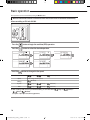
Checking the name of the parts
Buttons
⑫
⑨
⑧
①
②
⑱
⑬
⑮
⑳
③
⑤
⑥
⑦
④ ⑪ ⑩ ⑯⑲ ⑭
Classification
Unit
Related
Information
Button
Function
①
Operation On/Off
button
②
Mode button
③
⑰
Turns the unit power On/Off
Selects the desired unit operation
Temperature setting
Sets the desired temperature
button
④
Fan speed button
Changes the unit fan speed
⑤
Air Swing button
Changes the air flow direction to move upward or downward
⑥
Temp. button
⑦
Quiet/Sleep button
Checks the indoor temperature
Selects Quiet or Sleep operation for the unit
14
RHF050KHEA_IB,IM_E_32885-1.indd 14
2010-12-15 오전 11:26:51
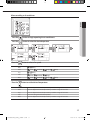
Classification
⑨
⑪
Blade button
Occupancy detection
button
Outdoor air intake
⑫
Schedule Button
Select the schedule setting function
⑬
User Set Button
Select the detailed setting function
⑩
⑭
Special
Function
Displays
Turns the AHU humidifying function On/Off
Selects a blade for individual control
Set the power to automatically turn off if there is nobody in
the room
Select the AHU Outdoor intake function
Navigational buttons Move between items or change the item value
⑮
Set button
Save your new settings
⑯
ESC button
Return to general mode from schedule and detailed setting screens
⑰
Delete button
⑱
Auto Clean button
Use the auto cleaning function for your unit
⑲
CO2/[kWh] button
Display the amount of CO2 and the power consumption
⑳
Filter Reset button
Turn off the filter cleaning displays (filter using time reset)
Ventilator
(ERV)
Related
Buttons
Function
Humidity button
ENGLISH
Unit
Related
Information
Button
⑧
Cancel the schedule setting
S-Plasma Ion button Choose the S-Plasma Ion function
Operation On/Off button Turn the Ventilator(ERV) On/Off
Mode button
Fan speed button
E.Saver button
Clean up button
Select the desired operation for the Ventilator(ERV)
Change the fan speed for your Ventilator(ERV)
Begin Energy Saving Operation
Select air purification through the in/out load controls
•After cleaning the filter, please press the Filter Reset button. The
lamp will turn off, and it will be turned
on again upon the next cleaning period.
•If you press a functional button not supported by the indoor unit, then the
lamp will turn on.
•If the temperature display setting is set to indoor temperature and you press the Temp. button,
the
lamp display will appear. (When you install the wired remote controller, the setting is available.)
•If you press the On/Off button when your Ventilator(ERV) is connected to a wired remote controller, then the
product and the Ventilator(ERV) might operate or stop at the same time or only the product might operate or stop.
The factory setting is set to simultaneous operation/stop. (When you install the wired remote controller, the setting
is available.)
•Although the product and the Ventilator(ERV) are set to simultaneous operation/stop,
you can individually control the product and the Ventilator(ERV) by using another controller
(e.g. wireless remote controller, central controller, S-net mini) except for a wired remote controller.
15
RHF050KHEA_IB,IM_E_32885-1.indd 15
2010-12-15 오전 11:26:54
Basic operation
Basic operations can be selected after pressing the Mode button.
When the wired remote controller is connected to an ERV with DX-COIL and an Air conditioner simultaneously
When controlling an ERV with DX-COIL
Press the
button to begin the ventilator(ERV) operation.
Press the
button to select the desired operation.
Press the
button to change the fan speed.
(High) ▷
Heat-EX
Quiet
(Turbo) ▷
(Medium)
Can’t change the fan speed.
Outing
(Medium)
By-Pass
(High) ▷
(Turbo) ▷
(Medium)
Auto
(High) ▷
(Turbo) ▷
(Medium)
※ After installing a CO2 sensor in your Ventilator(ERV), you can select from
(Auto)▹
(Medium).
(Exception : Quiet Operation, Outing Operation)
(High) ▹
(Turbo)▹
16
RHF050KHEA_IB,IM_E_32885-1.indd 16
2010-12-15 오전 11:26:56
When controlling an Air conditioner
ENGLISH
Press the
button to begin operating the air conditioners.
Press the
button to select the desired operation.
Press the
button to select a fan speed.
Auto
(Auto)
Cool
(Low) ,
Dry
(Medium),
(High),
Fan
(Low) ,
(Medium),
(High)
Heat
(Low) ,
(Medium),
(High),
Press the
(Auto)
(Auto)
(Auto)
button to set the desired temperature.
Auto
You can adjust the desired temperature by 1°C within a range of 18°C~30°C.
Cool
You can adjust the desired temperature by 1°C within a range of 18°C~30°C.
Dry
You can adjust the desired temperature by 1°C within a range of 18°C~30°C.
Fan
You can’t change the desired temperature.
Heat
You can adjust the desired temperature by 1°C within a range of 16°C~30°C.
17
RHF050KHEA_IB,IM_E_32885-1.indd 17
2010-12-15 오전 11:26:57
Basic operation
When controlling an ERV with DX-COIL and Air conditioner simultaneously
Operate the ERV with DX-COIL and Air conditioners separately by referring to the operation of only the ERV with
DX-COIL and only the Air conditioner.
•When you operate an ERV with DX-COIL only, cooling and heating operation is impossible.
•When you operate an ERV with DX-COIL and air conditioner at the same time, the ERV with DX-COIL follows the
operation of the Air conditioner.
When the wired remote controller is connected to an ERV with DX-COIL only
When you operate the ventilation operation of an ERV with DX-COIL only
Press the
button to begin the ventilator(ERV) operation.
Press the
button to select the desired operation.
Press the
button to change the fan speed.
When you operate the cooling and heating operation of an ERV with DX-COIL
A
B
Press the
operation.
(A or C) button to begin the ventilator(ERV)
Press the
operation.
(D) button to select the desired ventilator(ERV)
Press the
(E) button to change the fan speed.
Press the
(B) button to select cooling and heating operation.
C
D
E
•You cannot set the temperature by an ERV with DX-COIL only.
•You cannot select the dry operation if you operate an ERV with
DX-COIL only.
18
RHF050KHEA_IB,IM_E_32885-1.indd 18
2010-12-15 오전 11:26:58
Cleaning and maintaining the unit
Cleaning the Air filter
Remove 2 screws on the access panel.
ENGLISH
Clean the air filters at least twice a year. However, the frequency may vary depending on use and environment.
Clean the air filters more frequently in dusty place.
Make sure that the power supply is disconnected before cleaning the ventilator.
Take off the access panel from the ventilator.
Detach the air filters by pulling them forward.
There are totally 4 air filters on both sides of the
heat exchange element.
Screw
Air filter
Reassemble the air filters and access panel.
Make sure to insert the air filters correctly.
If not, dust may accumulate on the heat exchange
element decreasing the efficiency.
Remove all dust on the air filters with a vacuum
cleaner or a brush.
•Change the air filters in every two years. However, changing frequency may vary according to the used period and
condition.
•If the air filter is damaged, purchase it individually in a customer care center or an agency that you bought the
product.
• Make sure to turn off the power supply.
19
RHF050KHEA_IB,IM_E_32885-1.indd 19
2010-12-15 오전 11:27:00
Cleaning and maintaining the unit
Cleaning the Heat Exchange Element
Clean the Heat exchange element at least twice a year. However, the frequency may vary depending on use and environment.
Clean the Heat exchange element more frequently in dusty place.
Make sure that the power supply is disconnected before cleaning the ventilator.
Remove 2 screws on the access panel.
Take off the access panel from the ventilator.
Detach the 2 heat exchange elements in order.
The heat exchange element is heavy.
Take care not to drop it.
There are 2 heat exchange elements in the ventilator.
Make sure clean them at once.
Screw
Heat exchange element
Remove all dust and particles on the heat exchange elements with a nozzle of
a vacuum cleaner.
Take care not to attach the nozzle too close.
It may damage the heat exchange element.
Reassemble the heat exchange elements and access panel.
•If the heat exchange element is damaged, purchase it individually in a customer care center or an agency that you
bought the product.
•Make sure to turn off the power supply.
• Do not wash the heat exchange element. It may decrease its efficiency.
20
RHF050KHEA_IB,IM_E_32885-1.indd 20
2010-12-15 오전 11:27:01
Cleaning the Humidifier (Optional)
Remove 2 more screws.
ENGLISH
Remove 15 screws on the humidifier access panel.
Take off the humidifier access panel.
Screw
Submerge the humidifier element in water and
move up and down with care to release any dirt.
Remove the element as illustrated.
Do not scrub the humidifier element.
Do not spray water directly onto the humidifier
element with a hose.
Do not use detergent or
water hotter than 40°C.
Reassemble the humidifier element and access panel.
Check whether the humidifier element is correctly assembled. Otherwise, this may result in water leakage and
performance deterioration.
21
RHF050KHEA_IB,IM_E_32885-1.indd 21
2010-12-15 오전 11:27:02
Cleaning and maintaining the product
AA
Cleaning the Strainer (Optional)
Remove the Strainer cap.
Take out the mesh inside the strainer.
Strainer
Mesh
Cap
Clean the mesh with running water.
•Clean the mesh once a month.
22
RHF050KHEA_IB,IM_E_32885-1.indd 22
2010-12-15 오전 11:27:03
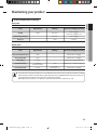
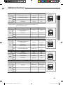
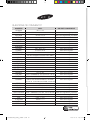
Maintaining your product
Period of Replacement & Cleaning
Parts
Replacement
Cleaning
Reasons for exchange or cleaning
Air filter
2 years
6 months
Dust clogging,
Performance deterioration
Heat exchange element
-
6 months
Dust clogging
Drain pan
-
1 year
Pollution
Parts
Replacement
Cleaning
Reasons for exchange or cleaning
Electronic feed water valve
5 years
-
Deterioration, Clogging
Flow control valve
5 years
-
Deterioration, Clogging
Water piping
10 years
-
Deterioration, pipe water leak
Humidifier element
7~10 years
(1,000hours/year)
1 year
Deterioration of saturation efficiency
10 years
1 month
(Heating season)
Deterioration, Clogging
ENGLISH
Basic parts
Option parts
Feed water strainer
•The product life and product durable years can be different from the table above according to installation condition
and maintenance situation. The table above is applicable when the use of ERV follows the instruction and does the
regular maintenance work and is in the general air conditioning condition.
(If the ERV performs round-the-clock operation, replacement interval can be reduced to 1/3~2/5)
23
RHF050KHEA_IB,IM_E_32885-1.indd 23
2010-12-15 오전 11:27:03
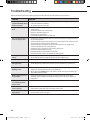
Troubleshooting
Refer to the following chart if the product operates abnormally. This may save time and unnecessary expenses.
PROBLEM
SOLUTION
The product does not
operate immediately after it
has been restarted.
•Because of the protective mechanism, the appliance does not start operating immediately
to keep the unit from overloading.
The product will start in 3 minutes.
The product does not work
at all.
•Check that the power plug is properly connected. Insert the power plug into the wall
socket correctly.
• Check if the circuit breaker is switched on.
• Check the sub power supply is on.
• Check if there is a power failure.
• Check your fuse. Make sure it is not blown out.
The cool (warm) air does not
come out of the product.
•Check if the set point temperature of the connected air conditioner is higher (lower) than
the current temperature.
•Check if the product has just been turned on. If so, wait 3 minutes. Cool air does not come
out to protect the compressor of the outdoor unit.
•Check if the product is installed in a place with a direct exposure to sunlight. Hang
curtains on windows to boost cooling efficiency.
• Check if the cover or any obstacle is not near the outdoor unit.
• Check if the refrigerant pipe is too long.
• Check if the product is only available in Cool mode.
• Check if the remote control is only available for cooling model.
The fan speed does not
change.
•Check if you selected Quiet mode.
The product automatically adjusts the fan speed to Auto in Quiet mode.
Timer function does not set.
• Check if you press the Power button on the remote control after you have set the time.
Odors permeate in the room
during operation.
•Check if the appliance is running in a smoky area or if there is a smell entering from
outside. Operate the product in Fan mode or open the windows to air out the room.
The product makes a
bubbling sound.
•A bubbling sound may be heard when the refrigerant is circulating through the
compressor. Let the product operate in a selected mode.
•When you press the Power button on the remote control, noise may be heard from the
drain pump inside the product.
Water is dripping from the
air flow blades.
•Check if the product has been cooling for an extended period of time with the air
flow blades pointed downwards. Condensation may generate due to the difference in
temperature.
The product does not turn
on or off with the wired
remote control.
• Check if you set the wired remote control for group control.
The wired remote control
does not operate.
•Check if TEST indicator is displayed on the wired remote control. If so, turn off the unit and
switch off the circuit breaker. Call your nearest contact center.
The indicators of the digital
display flashes.
•Press the Power button on the remote control to turn the unit off and switch the circuit
breaker off. Then, switch it on again.
24
RHF050KHEA_IB,IM_E_32885-1.indd 24
2010-12-15 오전 11:27:03
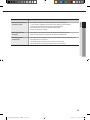
SOLUTION
The air does not come out
from the air outlet.
•Check whether air filter or heat exchange element is blocked by dust.
In case of dust accumulation, it may decrease the efficiency of the ventilator.
Clean the air filter and the heat eschange element frequently.
•Check whether the air intake or outlet is blocked by dust.
Remove all dust in the air intake.
Water drops from the
air intake.
•Check whether the ventilator is operated in By-Pass mode during heating.
When heating, make sure to operate the ventilator in Heat-EX mode.
Humidity operation
doesn’t work.
• Check whether the humidifier element is installed additionally for humidity operation.
•Check if the unit is in heat mode.
(Humidity operation works only when the unit is in heat mode.)
• The on/off operation status of humidity operation is not indicated.
ENGLISH
PROBLEM
25
RHF050KHEA_IB,IM_E_32885-1.indd 25
2010-12-15 오전 11:27:03
INSTALLATION PARTS
Safety precautions
Carefully follow the precautions listed below because they are essential to guarantee the safety of the equipment.
• Always disconnect the product from the power supply before servicing it or accessing its internal components.
• Verify that installation and testing operations are performed by qualified personnel.
• Verify that the product is not installed in an easily accessible area.
General information
Carefully read the content of this manual before installing the product and store the manual in a safe place in
order to be able to use it as reference after installation.
For maximum safety, installers should always carefully read the following warnings.
Store the operation and installation manual in a safe location and remember to hand it over to the new owner if the
product is sold or transferred.
This manual explains how to install an indoor unit with a split system with two SAMSUNG units. The use of other types
of units with different control systems may damage the units and invalidate the warranty.
The manufacturer shall not be responsible for damages arising from the use of non compliant units.
T
he product is compliant with the requirements of the Low Voltage Directive(72/23/EEC),
the EMC Directive(89/336/EEC) and the Directive on pressurized equipment(97/23/EEC).
The manufacturer shall not be responsible for damage originating from unauthorized changes or the improper
connection of electric and hydraulic lines. Failure to comply with these instructions or to comply with the requirements set
forth in the “Operating limits” table, included in the manual, shall immediately invalidate the warranty.
The product should be used only for the applications for which it has been designed: the indoor unit is not
suitable to be installed in areas used for laundry.
Do not use the units if damaged. If problems occur, switch the unit off and disconnect it from the power supply.
In order to prevent electric shocks, fires or injuries, always stop the unit, disable the protection switch and contact
SAMSUNG’s technical support if the unit produces smoke, if the power cable is hot or damaged or if the unit is very noisy.
Always remember to inspect the unit, electric connections, refrigerant tubes and protections regularly.
These operations should be performed by qualified personnel only.
The unit contains moving parts, which should always be kept out of the reach of children.
Do not attempt to repair, move, alter or reinstall the unit. If performed by unauthorized personnel, these operations
may cause electric shocks or fires.
Do not place containers with liquids or other objects on the unit.
All the materials used for the manufacture and packaging of the product are recyclable.
The packing material and exhaust batteries of the remote control(optional) must be disposed of in accordance with
current laws.
The product contains a refrigerant that has to be disposed of as special waste. At the end of its life cycle, the air
conditioner must be disposed of in authorized centers or returned to the retailer so that it can be disposed of correctly
and safely.
Installing the unit
IMPORTANT: When installing the unit, always remember to connect first the refrigerant tubes, then the electrical lines.
Always disassemble the electric lines before the refrigerant tubes.
Upon receipt, inspect the product to verify that it has not been damaged during transport. If the product appears
damaged, DO NOT INSTALL it and immediately report the damage to the carrier or retailer (if the installer or the
authorized technician has collected the material from the retailer.)
After completing the installation, always carry out a functional test and provide the instructions on how to operate
the product to the user.
Do not use the product in environments with hazardous substances or close to equipment that release free
flames to avoid the occurrence of fires, explosions or injuries.
The product should be used only for the applications for which it has been designed: the indoor unit is not
suitable to be installed in areas used for laundry.
26
RHF050KHEA_IB,IM_E_32885-1.indd 26
2010-12-15 오전 11:27:03
Our units must be installed in compliance with the spaces indicated in the installation manual to ensure either
ENGLISH
accessibility from both sides or ability to perform routine maintenance and repairs. The units’ components must be
accessible and that can be disassembled in conditions of complete safety either for people or things.
For this reason, where it is not observed as indicated into the Installation Manual, the cost necessary to reach and
repair the unit (in safety, as required by current regulations in force) with slings, trucks, scaffolding or any other means
of elevation won’t be considered in-warranty and charged to end user.
Hang down a blockage for bird in front of outdoor air suction duct. If something such as bird’s nest blocks the
air suction duct, it may result in oxygen shortage in indoors.
Power supply line, fuse or circuit breaker
Always make sure that the power supply is compliant with current safety standards. Always install the product in
compliance with current local safety standards.
Always verify that a suitable grounding connection is available.
Verify that the voltage and frequency of the power supply comply with the specifications and that the installed
power is sufficient to ensure the operation of any other domestic appliance connected to the same electric lines.
Always verify that the cut-off and protection switches are suitably dimensioned.
Verify that the product is connected to the power supply in accordance with the instructions provided in the
wiring diagram included in the manual.
Always verify that electric connections (cable entry, section of leads, protections…) are compliant with the electric
specifications and with the instructions provided in the wiring scheme. Always verify that all connections comply with
the standards applicable to the installation of products.
•Make sure that you earth the cables.
- Do not connect the earth wire to the gas pipe, water pipe, lighting rod or telephone wire.
If earthing is not complete, electric shock or fire may occur.
•Install the circuit breaker.
- If the circuit breaker is not installed, electric shock or fire may occur.
• Make sure that the condensed water dripping from the drain hose runs out properly and safely.
•Install the power cable and communication cable of the indoor and outdoor unit at least 1m away from the
electric appliance.
•Install the indoor unit away from lighting apparatus using the ballast.
- If you use the wireless remote control, reception error may occur due to the ballast of the lighting apparatus.
•Do not install the product in following places.
- Place where there is mineral oil or arsenic acid.
Resin parts flame and the accessories may drop or water may leak.
The capacity of the heat exchanger may reduce or the product may be out of order.
- The place where corrosive gas such as sulfurous acid gas generates from the vent pipe or air outlet.
The copper pipe or connection pipe may corrode and refrigerant may leak.
- The place where there is a machine that generates electromagnetic waves.
The product may not operate normally due to control system
- The place where there is a danger of existing combustible gas, carbon fiber or flammable dust.
The place where thinner or gasoline is handled.
Gas may leak and it may cause fire.
•Do not install the unit in a climate of high temperature and humidity. It may form dewdrop inside of the unit and
heat exchange element.
- Install & Operation ranges
Install condition
0~40°C, 80%RH below
Outdoor air condition
-15~40°C, 80%RH below
Indoor air condition
0~40°C, 80%RH below
•Noise may increase when there are large amount of exhausting air.
Be sure to install the duct based on standard air volume. When necessary, control the air volume by installing
volume damper. If the noise continues, install the noise chamber or flexible noise reducer additionally.
(Volume damper, noise chamber and flexible noise reducer are optional.)
27
RHF050KHEA_IB,IM_E_32885-1.indd 27
2010-12-15 오전 11:27:03
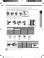
Accessories
The following accessories are supplied with the indoor unit.
The type and quantity may differ depending on the specifications.
User & Installation
manual
Insulation cover
pipe in
Flexible hose
Clamp hose
Insulation cover
pipe out
Insulation drain
Insulation cover
drain
Insulation pipe
Cable tie
Selecting the installation location
There must be no obstacles near the air inlet and outlet.
Install the indoor unit on a ceiling that can support its weight.
Maintain sufficient clearance around the indoor unit.
Make sure that the water dripping from the drain hose runs away correctly and safely.
The indoor unit must be installed in this way, that they are out of public access. (Not touchable by the users)
After connecting a chamber, insulate the connection part between the indoor unit and the chamber with t10 or thicker
insulation. Otherwise, there can be air leak or dew from the connection part.
Rigid wall without vibration.
Where it is not exposed to direct sunshine.
Where the replacement parts. (air filter, heat exchange element, humidifier element) can be removed and cleaned easily.
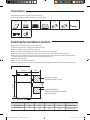
Space Requirements
'A' mm
Return Air
'C' mm
Supply Air
Inspection hole('E'mm)
'B' mm
'D' mm
for DX-COIL, Humidifier element
Inspection hole('E'mm)
for filter, heat exchange element, fan,
motor and damper
Exhaust Air Outdoor Air
Model
'A'
RHF050KHEA
1000
RHF100KHEA
1135
'B'
'C'
'D'
'E'
1553
600
200
450 x 450 or more
1763
800
300
550 x 550 or more
28
RHF050KHEA_IB,IM_E_32885-1.indd 28
2010-12-15 오전 11:27:04
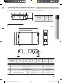
Selecting the installation location
The ventilator should be installed in a ceiling which has enough space above as seen in the picture.
20mm or more
Space for installation :
20mm or more 'B'mm
Model
'A'
'B'
RHF050KHEA
320
600
RHF100KHEA
440
800
ENGLISH
'A' mm
Dimension of the indoor unit
Unit : mm
D
E
B
A
C
①
②
④
③
F
F
Model
A
RHF050KHEA
1036
RHF100KHEA
1183
B
C
D
E
F
1000
987
1553
270
99
1135
1189
1763
340
84
No.
Name
①
Liquid pipe connection
ø6.35 (1/4”)
②
Gas pipe connection
ø12.70 (1/2”)
③
Drain pipe connection
④
Nominal diameter for duct
Description
VP25 (OD ø32, ID ø25)
RHF050KHEA
ø200
RHF100KHEA
ø250
29
RHF050KHEA_IB,IM_E_32885-1.indd 29
2010-12-15 오전 11:27:05
Indoor unit installation
It is recommended to install the Y-joint before installing the indoor unit.
1.Insert bolt anchors, use existing ceiling supports or construct a
suitable support as shown in figure.
Concrete
2.Install the suspension bolts depending on the ceiling type.
•Ensure that the ceiling is strong enough to support the weight
of the indoor unit. Before hanging the unit, test the strength
of each attached suspension bolt.
•If the length of suspension bolt is more than 1.5m, it is required
to prevent vibration.
•If this is not possible, create an opening on the false ceiling in
order to be able to use it to perform the required operations
on the indoor unit.
Insert
Hole in anchor
Hole in plug
Suspension bolt( 3/8” or M10)
Ceiling support
3.Fit two nuts on each suspension rod allowing space for the indoor
unit between.
•You must install the suspension bolts more
than four when installing the indoor unit.
4.Hang the indoor unit to the suspension bolts between two nuts.
Nut
Washer
5.Tighten the nuts securely to clamp the brackets on the unit and
prevent movement.
Rubber
Washer
Nut
Nut
6.Adjust level of the unit by using measurement plate for all 4 sides.
1° or less
OA
SA
Horizontal line
OA
SA
1° or less
SA
RA
Drain hole
SA
RA
•For proper drainage of condensate, give 1° or less slant to the side of the unit which will be connected with the
drain hose, as shown in the figure.
30
RHF050KHEA_IB,IM_E_32885-1.indd 30
2010-12-15 오전 11:27:05
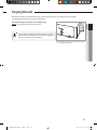
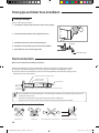
Purging the unit
On delivery, the indoor unit is loaded with inert gas. All this gas must therefore be purged before connecting the
assembly piping. To purge the inert gas, proceed as follows.
Unscrew the pinch pipe at the end of each refrigerant pipe.
ENGLISH
Result: All inert gas escapes from the indoor unit.
•To prevent dirt or foreign objects from getting into the pipes
during installation, do NOT remove the pinch pipe completely
until you are ready to connect the piping.
The designs and shape are subject to change
according to the model.
31
RHF050KHEA_IB,IM_E_32885-1.indd 31
2010-12-15 오전 11:27:05
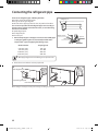
Connecting the refrigerant pipe
There are two refrigerant pipes of differing diameters:
A smaller one for the liquid refrigerant
A larger one for the gas refrigerant
The inside of the copper pipe must be clean, dry and free from debris.
The connection procedure for the refrigerant pipes varies according to
the exit position of the pipes from the indoor unit, as seen when facing
the indoor in the “A” side.
Liquid refrigerant port
Gas refrigerant port
Drain hose port
1.Remove the pinch pipe on the pipes and connect the assembly pipes
to each pipe, tightening the nuts, first manually and then with a
torque wrench, a spanner applying the following torque.
Outer Diameter
6.35 mm (1/4")
9.52 mm (3/8")
12.70 mm (1/2")
15.88 mm (5/8")
Refrigerant oil
Torque wrench
Spanner
Flare nut
Union
Torque (kgf•cm)
145~175
333~407
505~615
630~769
•Must apply refrigerant oil on the flaring area to prevent a leak.
2.Ensure there are no kinks or cracks on pipe bends.
A
Gas refrigerant port
Liquid refrigerant port
Drain hose connection port
The designs and shape are subject to change according to the model.
32
RHF050KHEA_IB,IM_E_32885-1.indd 32
2010-12-15 오전 11:27:06
Cutting/flaring the pipe
1. Make sure that you prepared the required tools. (pipe cutter, reamer, flaring tool and pipe holder)
2. If you want to shorten the pipe, cut it using a pipe cutter ensuring that the cut edge remains at 90° with the side of the
pipe. There are some examples of correctly and incorrectly cut edges below.
Rough
ENGLISH
Oblique
Pipe
cutter
Burr
Pipe
3. To prevent a gas leak, take care not to allow burrs to enter the pipe and clean the flare.
4. Carry out flaring work using flaring as shown below.
A
Flaring tool
York
Die
Die
Clutch type
Wing nut type
Copper pipe
Outer diameter (mm)
Flare tool for
R410A clutch type
ø6.35 mm
ø9.52 mm
ø12.70 mm
ø15.88 mm
0~0.5
0~0.5
0~0.5
0~0.5
Flare nut
Copper
pipe
Pipe
Flare
A(mm)
Conventional flare tool
Clutch type
Wing nut type
0~0.5
1.5~2.0
0~0.5
1.5~2.0
0~0.5
1.5~2.0
0~0.5
1.5~2.0
5. Check if you flared the pipe correctly (see examples of incorrectly flared pipes below).
Correct
Inclined
Damaged
Surface
Cracked
Uneven
Thickness
6. Align the pipes and tighten the flare nuts first manually and then with a torque wrench, applying the following torque.
Indoor outlet pipe
Connecting pipe
Outer diameter Connection
Flare dimen(mm)
Torque(kgf•cm) sion (mm)
145~175
8.70~9.10
ø6.35 mm
333~407
12.80~13.20
ø9.52 mm
505~615
16.20~16.60
ø12.70mm
630~769
19.30~19.70
ø15.88 mm
Flare shape
(mm)
90° ±2°
45° ± 2°
Flare nut
R 0.4~0.8
• Purge pipe work with oxygen free nitrogen while brazing.
33
RHF050KHEA_IB,IM_E_32885-1.indd 33
2010-12-15 오전 11:27:06
Performing leak test & insulation
Leak test
LEAK TEST WITH NITROGEN (before opening valves)
In order to detect basic refrigerant leaks, Pressure test the system to
4.1MPa with oxygen free nitrogen before vacuuming the system.
LEAK TEST WITH R410A (after opening valves)
Once the valves are opened and gauge manifold is disconnected,
use a leak detector to check for leaks.
•Release the nitrogen slowly and safely before connecting
gauges to the Vacuum pump.
Leak check
The designs and shape are subject to change
according to the model.
Insulation
1.To avoid condensation problems, place T13.0 or thicker Acrylonitrile
Butadien Rubber separately around each refrigerant pipe.
No gap
• Always make the seam of pipes face upwards.
•Any joints in the insulation must be taped or glued with
approved materials to prevent water leaks.
NBR(T13.0 or thicker)
2.Wind insulating tape around the pipes and drain hose avoiding to
compress the insulation too much.
3.Finish wrapping insulating tape around the rest of the pipes leading
to the outdoor unit.
4.The pipes and electrical cables connecting the indoor unit with the
outdoor unit must be fixed to the wall with suitable fixings.
Insulation cover pipe
Insulation pipe
Indoor unit
Be sure to overlap
the insulation
•Must fit tightly against
body without any gap.
34
RHF050KHEA_IB,IM_E_32885-1.indd 34
2010-12-15 오전 11:27:07
5. Selecting the insulation for the refrigerant pipes.
ENGLISH
Insulate the gas side and liquid side pipe referring to the thickness according to the pipe size.
The thickness according to the pipe size is a standard of the indoor temperature of 27°C and humidity of 80%.
If installing in an unfavorable conditions, use thicker one.
Insulator’s heat-resistance temperature should be more than 120°C.
Pipe size (mm)
Ø6.35~ Ø15.88
-
Minimum thickness
of insulator (mm)
Remarks
PE foam EPDM foam
13
10
If you install the pipe underground, at the seaside, a spa or on the
lake, use 1 grade thicker one according to the pipe size.
25
19
Refrigerant pipe before EEV kit and MCU or without EEV kit and MCU
You can contact the gas side and liquid side pipes but the
Insulation
Insulation
pipes should not be pressed.
When contacting the gas side and gas side pipe, use 1 grade
thicker insulator.
Liquid pipe
Gas pipe
Refrigerant pipe after EEV kit and MCU
10mm
10mm
10mm
Install the gas side and liquid side pipes, leave 10mm of space.
When contacting the gas side and liquid side pipe, use 1 grade
thicker insulator.
Gas pipe
Liquid pipe
•Install the insulation not to get wider and use the adhesives on the connection part of it to prevent moisture from
entering.
• Wind the refrigerant pipe with insulation tape if it is exposed to outside sunlight.
• Install the refrigerant pipe respecting that the insulation does not get thinner on the bent part or hanger of pipe.
• Add the additional insulation if the insulation plate gets thinner.
• Ensure that the pipe insulation is not crushed eg: on bends, where supported by hangers, where cable ties are used.
Hanger
Additional insulation
a
a×3
Refrigerant pipe insulation
35
RHF050KHEA_IB,IM_E_32885-1.indd 35
2010-12-15 오전 11:27:07
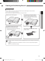
Drain pipe and drain installaton
AA
1. Unscrew the 4 tapped screws to remove the cover of the drain hose
connection port.
Drain hose connection port
2. Insert the flexible hose to the drain hose port.
•Fix the flexible hose to the indoor unit wiht the supplied cable
clamp securely.
(Use the screwdriver to fix the flexible hose securely.)
Cable clamp
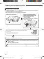
3. Install the drain hose so that its length can be as short as possible. Internal diameter of the drain hose should be the
same or slightly bigger than the external diameter of the drain hose port.
Inner diameter of the drain hose
32mm(Inner diameter)
• Install the drain hose with a slope away from the unit to give adequate drainage of condensate.
•Fix the flexible hose to the PVC with the supplied cable tie securely.
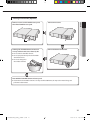
4. Wrap the drain hose with the insulation drain as shown in figure and secure it.
Indoor
unit
Cable-tie
Clamp
Insulation drain hose
Insulation cover drain
•Must fit tightly against
body without any gap.
No gap
36
RHF050KHEA_IB,IM_E_32885-1.indd 36
2010-12-15 오전 11:27:08
Drain pipe and drain hose installaton
Drainpipe Connection
1. Install horizontal drainpipe with a slope of 1/100 or more and fix it by hanger space of 1.0~1.5m.
ENGLISH
2. Install U-trap at the end of the drainpipe to prevent any odors reaching the indoor unit.
3. Do not install the drain with an upward inclination as it will prevent drainage.
1~1.5m
Hanger
Flexible hose
Ceiling
Horizontal drainpipe
more than 1/100 slope
• Do not use the drain pump and allow the natural drainage.
Centralized Drainage
1. Install horizontal drainpipe with a slope of 1/100 or more and fix it by hanger space of 1.0~1.5m.
100mm or more
2. Install U-trap at the end of the drainpipe to prevent a nasty smell to reach the indoor unit.
Ceiling
Horizontal drainpipe
more than 1/100 slope
• Do not use the drain pump and allow the natural drainage.
37
RHF050KHEA_IB,IM_E_32885-1.indd 37
2010-12-15 오전 11:27:08
Drain pipe and drain hose installaton
Testing the drainage
Prepare a little water about 5 liters.
1.Pour water into the base pan in the indoor unit as shown in figure.
2.Confirm that the water flows out through the drain hose.
3.Check drain water drops at the end of the drain pipe.
Drainpipe
4.Check that no water leaks from joints in the drain installation.
5. Reassemble the cover of water supply intake.
Drain water drops
Duct connection
Make sure to insulate the duct refering to the picture.
Wind the aluminum tape securely round the duct connection so that the air in the duct does not leak.
To prevent rain from permeating duct connection, install the two outdoor ducts (OA, EA) on a slope.
To prevent condensation from forming, insulate the three ducts. (Outdoor ducts and Indoor supply air duct)
(Material: Glass wool of 25 mm thick)
Insulation material(Locally procured)
Outdoor Air duct,
Exhaust air duct
Inclination
(1/100~1/50)
Aluminium tape (Locally procured)
Supply Air duct
Aluminium tape (Locally procured)
•The use of flexible hose made of fiber glass is recommended to minimize noise. Install the duct at least over 3m
to reduce the noise as well.
• If the duct is not attached correctly and securely, it may result in malfunction.
• To prevent a short circuit, install the indoor air intake as far away as possible from an air outlet.
Examples of incorrect duct installation
Extreme bend
Multi bend
Narrow diameter of connection part
A bend right next to the outlet
38
RHF050KHEA_IB,IM_E_32885-1.indd 38
2010-12-15 오전 11:27:09
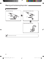
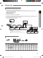
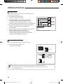
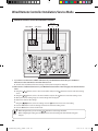
Wiring work
Power and communication cable connection
1.Before wiring work, you must turn off all power source.
ENGLISH
2.Indoor unit power should be supplied through the breaker(ELCB or MCCB+ELB) separated by the outdoor power.
ELCB: Earth Leakage Circuit Breaker
MCCB:Molded Case Circuit Breaker
ELB:Earth Leakage Breaker
3.The power cable should be used only copper wires.
4.Connect the power cable{1(L), 2(N)} among the units within maximum length and communication cable(F1, F2) each.
5.Connect V1, V2(for DC12V) and F3, F4(for communication)
when installing the wired remote control.
Outdoor Unit
Wired Remote
Control
220-240V~
ELCB
L
Indoor Unit 1
Indoor Unit 2
ERV with DX-COIL
h ELCB : Essential Installation
WARNING :
Power off before connecting any wires;
Indoor PBA will be damaged while V1,V2,F3,F4 short each
other.
EEV kit
N
MCCB+
ELB
N
Indoor Unit 4
Indoor Unit 5
L
N
L
N
L
Indoor Unit 6
h Ceiling, wall-mounted indoor unit.
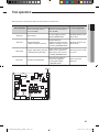
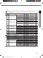
Selecting compressed ring terminal
Silver solder
B
D
d1
E
Norminal Norminal
Standard
Standard
dimensions dimensions Standard
Allowance
Allowance
Allowance
dimension
dimension
Min.
for cable for screw dimension
(mm)
(mm)
(mm)
(mm)
(mm)
(mm)
(mm2)
(mm)
4
6.6
+0.3
1.5
±0.2
3.4
1.7
±0.2
4.1
4
8
-0.2
4
6.6
+0.3
2.5
±0.2
4.2
2.3
±0.2
6
4
8.5
-0.2
+0.3
4
4
9.5
±0.2
5.6
3.4
±0.2
6
-0.2
F
Min.
6
6
5
L
d2
t
Standard
Allowance
Max. dimension
Min.
(mm)
(mm)
+0.2
16
4.3
0.7
0
+0.2
17.5
4.3
0.8
0
+0.2
20
4.3
0.9
0
39
RHF050KHEA_IB,IM_E_32885-1.indd 39
2010-12-15 오전 11:27:09
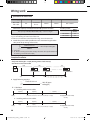
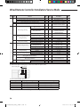
Wiring work
Specification of electric wire
Power supply
MCCB
ELB or ELCB
Power cable
Earth cable
Communication cable
Max : 242V
Min : 198V
XA
X A, 30mmA
0.1 sec
2.5mm2
2.5mm2
0.75~1.5mm2
Decide the capacity of ELCB(or MCCB+ELB) by below formula.
Rating current
Model
Rating
current
RHF050KHEA
1.7A
RHF100KHEA
3.7A
The capacity of ELCB(or MCCB+ELB) X [A] = 1.25 X 1.1 X ∑Ai
T X : The capacity of ELCB(or MCCB+ELB).
T ∑Ai : Sum of Rating currents of each indoor unit.
T Refer to each installation manual about the rating current of indoor unit.
Decide the power cable specification and maximum length within
10% power drop among indoor units.
n
Coef×35.6×Lk×ik
k=1
1000×Ak
∑(
) < 10% of input voltage[V]
T coef: 1.55
T Lk: Distance among each indoor unit[m], Ak: Power cable specification[mm2]
ik: Running current of each unit[A]
Example of Installation
- Total power cable length L = 100(m), Running current of each units 1[A]
- Total 10 indoor units were installed
10[A]
ELCB
9[A]
1[A]
or MCCB+
ELB
Indoor unit1
0[m]
Indoor unit2
10[m]
Indoor unit10
20[m]
100[m]
Apply following equation.
n
Coef×35.6×Lk×ik
k=1
1000×Ak
∑(
)<
10% of input
voltage[V]
hCalculation
Installing with one size cable.
2.5[mm2]
2.5[mm2]
-2.2[V]
-2.0[V]
220[V]
-(2.2+2.0+1.8+1.5+1.3+1.1+0.9+0.7+0.4+0.2)=-11.2[V]
Installing with two size cables.
4.0[mm2]
220[V]
············ 2.5[mm2] ············
4.0[mm2]
-1.4[V]
208.8[V](Within 198V~242V)
it's okay
············ 2.5[mm2] ············
-1.2[V]
-(1.4+1.2+1.8+1.5+1.3+1.1+0.9+0.7+0.4+0.2)=-10.5[V]
209.5[V](Within 198V~242V)
it's okay
40
RHF050KHEA_IB,IM_E_32885-1.indd 40
2010-12-15 오전 11:27:09
ENGLISH
• Select the power cable in accordance with relevant local and national regulations.
• Wire size must comply with local and national code.
• For the power cable, use the grade of H07RN-F or H05RN-F materials.
• You should connect the power cable into the power cable terminal and fasten it with a clamp.
• The unbalanced power must be maintained within 10% of supply rating among whole indoor units.
•If the power is unbalanced greatly, it may shorten the life of the condenser. If the unbalanced power is exceeded
over 10% of supply rating, the indoor unit is protected, stopped and the error mode indicates.
•To protect the product from water and possible shock, you should keep the power cable and the connection cord
of the indoor and outdoor units in the iron pipe.
•Connect the power cable to the auxiliary circuit breaker.
An all pole disconnection from the power supply must be incorporated in the fixed wiring(≥3mm).
• You must keep the cable in a protection tube.
• Keep distances of 50mm or more between power cable and communication cable.
•Maximum length of power cables are decided within 10% of power drop. If it exceeds, you must consider another
power supplying method.
•The circuit breaker(ELCB or MCCB+ELB) should be considered more capacity if many indoor units are connected
from one breaker.
• Use round pressure terminal for connections to the power terminal block.
•For wiring, use the designated power cable and connect it firmly, then secure to prevent outside pressure being
exerted on the terminal board.
•Use an appropriate screwdriver for tightening the terminal screws. A screwdriver with a small head will strip the
head and make proper tightening impossible.
• Over-tightening the terminal screws may break them.
• See the table below for tightening torque for the terminal screws.
Tightening torque(kgf•cm)
M4
12.0~14.7
41
RHF050KHEA_IB,IM_E_32885-1.indd 41
2010-12-15 오전 11:27:09
Indoor unit setting
Power and communication cable connectiona
1. Before installing the indoor unit, assign an address to the indoor unit according to the air conditioning system plan.
2. The address of the indoor unit is assigned by adjusting MAIN(SW01, SW02) and RMC(SW03, SW04) rotary switches.
SW01
SW02
SW03
SW04
The designs and shape are subject to
change according to the model.
SW05
SW06
SW07
SW08
SW09
Setting Main Address
The MAIN address is for communication between the indoor unit and the outdoor unit.
Therefore, you must set it to operate the product properly.
You can set the MAIN address from ‘00’ to ‘99’ by mixing SW01 and SW02.
The MAIN address from ‘00’ to ‘99’ should differ from each other.
Check the indoor unit address on the plan that you are to install and set the address according to
the plan.
•You may not need to set main address if you selected Auto Address Setting from the outdoor unit: see details
on the outdoor unit installation manual.
For Example
When MAIN address is set as "12".
Setting RMC Address
The SW03, SW04 RMC switch is the address setting switch for controlling the indoor unit with the
centralized controller.
You must set the SW03,SW04 and K2 switch when using the centralized controller.
You don't have to set the SW03 and SW04 RMC switch when not suing the centralized controller.
For Example
42
When RMC address is set as "12".
SW03
RHF050KHEA_IB,IM_E_32885-1.indd 42
SW04
2010-12-15 오전 11:27:10
Additional functions
No.
ON
OFF
K1
External room sensor
Not use
Use
K2
Centralized controller
Not use
Use
K1 K2 K3 K4
ENGLISH
SW05
Function
K3
-
-
-
K4
Humidifier
Not use
Use
SW05
K5 K6 K7 K8
gK1 OFF
Heating mode : Setting temperature compensation value = 0°C
Thermo OFF Fan OFF
No.
SW06
Function
ON
OFF
K5
Heating Current Temperature
Compensation
+2°C
+5°C
K6
Filter Time
1,000 hours
2,000 hours
K7
-
-
-
K8
-
-
-
Function
ON
OFF
Indoor Expansion Valve For
Heating Stop
160 step
35/160 step
No.
K9
SW07
K10
Master/Slave
Slave
Master
K11
External control
Not use
Use
K12
External control output
Thermo Check
Operartion
Check
Function
ON
OFF
K13
External damper
Not use
Use
K14
S-Plasma ion
Not use
Use
K15
CO2 sensor
Not use
Use
K16
-
-
-
Function
ON
OFF
K17
Clean up
Exhaustion air
RPM is fixed as
Quiet mode RPM
Supply air RPM
is fixed as Quiet
mode RPM
K18
-
-
-
K19
-
-
-
K20
-
-
-
No.
SW08
No.
SW09
SW06
K9 K10 K11 K12
SW07
K13 K14 K15 K16
SW08
K17 K18 K19 K20
SW09
43
RHF050KHEA_IB,IM_E_32885-1.indd 43
2010-12-23 오후 1:03:20
Additional functions
External Control
Use an external control to interlock control the ventilator with external
device or external contact point.
It connects both sides of EXT1.
- Only 1 unit can be connected.
The picture displays the condition that external
controller, kitchen hood and humid sensor are
connected. If the external controller 1 is set to ON
position, ventilator is operated in the last used condition.
If you enter a kitchen hood, the supply air operates in
Turbo fan speed and exhaust air operates in
Low fan speed.
When a signal comes to the humidification sensor, the
ventilator (ERV) continues its operation.
However, the humidity solenoid valve of the
ventilator (ERV) will be closed and this will result in
stopping the humidification operation.
Humid sensor
Kitchen hood
External control 1
Humid HOOD EXT1
sensor
Sub power supply
contact point
Humid sensor is not supplied.
Connecting External Device
Connect to use humidifiers and dampers with the ventilator.
Turn off the option switch to use,
-K
15: The use of dampers
SW07
K13 K14 K15 K16
DAMPER
DAMPER
•If the ventilator is operated, the external damper is operated as well if it had been installed.
•Make sure that the current is not exceed to 0.5A. When you connect an external device over 0.5A,
use an extra terminal relay.
44
RHF050KHEA_IB,IM_E_32885-1.indd 44
2010-12-15 오전 11:27:10
Trial operation
When you press the trial operation button, the unit operates as the table below.
ENGLISH
Operation
TACT S/W PUSH
Power supply LED
When the humidity option is
not used. (K4 ON)
When the humidity option is
used. (K4 OFF)
One time
Not working
Start water supply by opening
humidity SOLENOID VALVE.
LED lamp will be on and
off one time
Two times
Damper operation
* Opens and closes one time
Damper operation
* Opens and closes one time.
* Maintain the open status of
humidity SOLENOID VALVE
LED lamp will be on and
off two times.
Three times
Supply / Exhaust Fan operation
Supply / Exhaust FAN operation * Turbo breeze is generated
* Turbo breeze is generated
*M
aintain the open status of
humidity SOLENOID VALVE
LED lamp will be on and off
three times.
Four times
Cancel the trial operation
Cancel the trial operation
* Stop water supply by
turning off humidity
SOLENOID VALVE
Return to the power
supply LED.
TACT S/W
45
RHF050KHEA_IB,IM_E_32885-1.indd 45
2010-12-15 오전 11:27:11
Final checks and user tips
To complete the installation, perform the following checks and tests to ensure that the product operates correctly.
1. Check the following.
Strength
of the installation site
of pipe connection to detect a gas leak
Electric wiring connections
Heat-resistant insulation of the pipe
Drainage
Earth conductor connection
Correct operation (follow the steps below)
Insulation
Tightness
After finishing the installation of the product, you should explain the following to the user. Refer to appropriate pages in the
user & installation manual.
1. How to start and stop the product
2. How to select the modes and functions
3. How to adjust the temperature and fan speed
4. How to adjust the airflow direction
5. How to set the timers
6. How to clean and replace the filters
• W
hen you complete the installation successfully, hand over the user & installation manual to the user for storage in
a handy and safe place.
46
RHF050KHEA_IB,IM_E_32885-1.indd 46
2010-12-15 오전 11:27:11
Troubleshooting
If an error occurs during the operation, The Wired Remote controller show that Error mode.
- When ERRORS related to cooling and heating operation occur, the ventilator (ERV) continues to perform in normal operation.
- When ERRORS related to a ventilator (ERV) occur, it stops operating.
ENGLISH
ERROR CODE DISPLAY on Wired remote controller
Error code
Explanation
E101
No communication between indoor unit and outdoor unit
E102
Indoor unit receiving the communication errorfrom outdoor unit
E122
EVA-IN Sensor(open/short)
E123
EVA-OUT Sensor(open/short)
E128
Breakaway of EVA-IN Sensor
E129
Breakaway of EVA-OUT Sensor
E174
EVA-INAir sensor(open/short)
E151
Error of EEV open
E152
Error of EEV close
E161
Error of mixed operation
E201
Communication error from outdoor unit due to the mismatching of the
communication numbers and installed numbers after tracking
E121
Indoor Temperature Sensor(open/short)
E175
Outdoor Temperature Sensor(open/short)
E139
CO2 sensor (open/short)
E162
EEPROM ERROR
E163
EEPROM option setting error
E186
SPI Error
E561
Supply Air Fan Motor error
E562
Exhaust Air Fan Motor error
E654
Damper ERROR (When there is no switch input for 100 seconds while
monitoring the damper)
Classifications
Errors related to
cooling and heating
operation
Errors related to
ventilator (ERV)
operation
47
RHF050KHEA_IB,IM_E_32885-1.indd 47
2010-12-23 오후 1:03:20
Wired Remote Controller Installation/Service Mode
Additional Functions of Your Wired Remote Controller
Data bit
Main Menu
Sub-menu
1 2 3 4
5 6
1. If you want to use the various additional functions for your Wired Remote Controller, press the Set and
Esc buttons at the same time for more than three seconds.
You will enter the additional function settings, and the [main menu] will be displayed.
2. Refer to the list of additional functions for your Wired Remote Controller on the next page, and select the desired
menu.
Using the [∧]/[∨] buttons, select a main menu number and press the [>] button to enter the sub-menu setting
screen.
Using the [∧]/[∨] buttons, select a sub-menu number and press the [>] button to enter data setting screen.
When you enter the setting stage, the current setting will be displayed.
Refer to the chart for data settings.
Using the [∧]/[∨] buttons, select the settings. Press the [>] button to move to the next setting.
Press the Set button to save the settings and exit to the sub-menu setting screen.
Press the Esc button to exit to normal mode.
• While setting the data, you can use the [<]/[>] buttons to set the range of Data bit.
•While configuring the setting, press the Esc button to exit to the setting sub-menu without saving your
changes.
48
RHF050KHEA_IB,IM_E_32885-1.indd 48
2010-12-15 오전 11:27:11
ENGLISH
•If your indoor machine does not support the setting mode, then you may not be able to edit the settings
or apply your changes.
Main Sub
menu menu
1
2
1
3
4
5
6
7
0
2
3
1
2
1
2
3
4
5
6
Data Factory
bit setting
Function
Wireless remote controller
Option setting/checking (1)
Wireless remote controller
Option setting/checking (2)
Description
Unit
Cooling/Heating selection
1
0
Use of wireless remote controller
MAIN/SUB wired remote
controller
Temperature unit
2
1
0 – Cooling/Heating,
1 – Cooling only
0 – No use, 0 - Use
3
0
0 –MAIN, 1- SUB
4
0
Temperature sensor selection
1
0
Use of average temperature
Use of Auto mode
2
3
0
1
Temperature display
4
0
AC On/Off button function
5
0
1
2
3
4
1
2
3
4
1,2,3
4,5,6
1,2
3,4
1
0
0
0
0
0
0
0
0
0
0
0
Lock of Blade1
Lock of Blade2
Lock of Blade3
Lock of Blade4
Use of By-Pass mode
ERV option
Use of Auto mode
Use of air purification mode
Setting/checking
Use of external control
Temperature control reference
Room Temperature
compensation
Temperature compensation value
Number of indoor units
Number of connected units
Number of ERVs
Temperature increment/decrement (°C only)
Blade
setting/checking
Factory option setting
Software code
Software version
Indoor unit room temperature
Indoor unit EVA IN temperature
Indoor unit EVA OUT temperature
Indoor unit EEV step
Use of central control
Use of drain pump
Indoor unit option checking (1)
Use of electric heater
Use of hot water coil
Use of external control
Use of RPM compensation
Filter time
Indoor unit option checking (2)
Heating temperature
compensation
EEV stop step in heating
-
0 – Celcius(°C), 1 – Fahrenheit(°F)
0 – Indoor unit,
1 – Wired remote controller
0 – No use, 0 - Use
0 – No use, 0 - Use
0 – Set temperature,
1 - Room temperature
0 – Indoor unit + ERV,
1 – Indoor unit only,
2 – ERV only,
0 – Unlock, 1 – lock
0 – Unlock, 1 – lock
0 – Unlock, 1 – lock
0 – Unlock, 1 – lock
0 – No use, 1 - Use
0 – No use, 1 - Use
0 – No use, 1 - Use
0 – No use, 1 - Use
-9 ~ 40(°C)
0.1(°C)
-9.9 ~ 9.9(°C)
0.1(°C)
0 ~ 16
0 ~ 16
0-1°C, 1-0.5°C, 2-0.1°C
0 – Unchanged
1 – Factory setting
Software code
Software version
Room temperature
°C
EVA IN temperature
°C
EVA OUT temperature
°C
EEV step
0 – No use, 1 - Use
0 – No use, 1 - Use
0 – No use, 1 - Use
0 – No use, 1 - Use
0 – No use, 1 - Use
0 – No use, 1 - Use
0 – 2000 hours, 1 – 1000 hours
-
1
0
1~6
1~6
1,2,3
1,2,3
1,2,3
1,2,3
1
2
3
4
1
2
3
-
4
-
0-2°C, 1-5°C
-
5
-
0 – 1/80 steps, 1 – 80
-
49
RHF050KHEA_IB,IM_E_32885-1.indd 49
2010-12-15 오전 11:27:11
Wired Remote Controller Installation/Service Mode
Main Sub
menu menu
2
Indoor unit main address checking
Indoor unit main address setting (outdoor unit reset is needed to set)
Indoor unit RMC address setting/checking
Indoor unit option code setting/checking
3
Indoor unit option switch setting/checking
1
4
Function
1
5
2
3
1
2
6
3
4
5
0
AHU setting/checking
Setting/checking the
differential value
RPM setting/checking
filter performance
humidity setting/checking
Use of discharge
temperature control
AHU discharge temperature
setting/checking
Cooling discharge temperature
Heating discharge temperature
Cooling discharge temperature
Fresh Duct discharge
temperature checking
Heating discharge temperature
Use of cold air prevention
Use of humidification when
Heating thermo off
ERV Plus setting/checking
Use of fan operation in Defrost
Use of humidification when Heating
Cooling
ERV Plus temperature
setting/checking
Heating
Set temperature
ERV Plus Auto mode
temperature setting/checking
Set temperature difference
Setting/checking the compensating temperature A under the
Heating EEV control for ERV Plus
Checking the compensating temperature B under the Heating
EEV control for ERV Plus
Air supply RPM
ERV Plus fan RPM setting/
checking
Air exhaustion RPM
Factory setting
Data Factory
bit setting
Description
Unit
Main address (0~63)
Main address (0~63)
RMC address (00H~2FH)
Indoor unit option code (24 bits)
Refer to the indoor unit
installation manual for details
-
1,2
3,4
5,6
1)*
-
1)*
-
1,2
-
0~30
1
3,4
-
1 RPM
5
-
6
-
0~25
0 – Pre
1 – Medium performance
2 –High performance
0 – 30, 1 - 40, 2 - 50
1
-
0 – No use, 1 - Use
-
3,4
5,6
1,2
3,4
1
-
10 ~25°C
28 ~43°C
13~25
18~30
0 – No use, 1 - Use
1°C
1°C
1°C
1°C
-
2
-
0 – No use, 1 - Use
-
3
4
1,2
3,4
1,2
3,4
-
0 – No use, 1 - Use
0 – No use, 1 - Use
15~30°C
15~30°C
15~30°C
5~15°C
1°C
1°C
1°C
1°C
1,2
-
0~10°C
1°C
0 – Non use of humidifier(0°C)
1 – Use humidifier(10°C)
10~27 RPM
10~27 RPM
0 – No use, 1– Factory setting
1 RPM
1 RPM
-
3,4
-
1,2
3,4
1
-
-
-
-
1)* Data1 is the option setting page. / Data2~6 stand for the option codes.
Option Setting Page
Option Code
12 34
56
You can set the 24 digits options.
Page
PAGE 1
PAGE 2
PAGE 3
PAGE 4
PAGE 5
Option Settings
1st~5th digit option setting
6th~10th digit option setting
11th~15th digit option setting
16th~20th digit option setting
21th~24th digit option setting
How to Move Between Pages
Press the [>] button to go to PAGE 2.
Press the [>] button to go to PAGE 3.
Press the [>] button to go to PAGE 4.
Press the [>] button to go to PAGE 5.
-
Regardless of Celsius and Fahrenheit setting, service mode setting is available only with Celsius.
50
RHF050KHEA_IB,IM_E_32885-1.indd 50
2010-12-15 오전 11:27:12
The example of ERV PLUS option setting method
(Main menu) will be displayed and then press the [∧]/[∨] button to select no.6.
ENGLISH
1. Press Set and ESC buttons at the same time for more than 3 seconds.
2. Press [>] button to select the number you will set.
Press [∧]/[∨] button and select no.1
3. Press [>] button to enter the data setting stage.
When you enter the setting stage, the current setting value will be displayed.
Example of data setting stage display
Data bit
12 34
Data1: Nonuse of cold breeze prevention
Data2: Cold breeze prevention: Non use of humidification when the heating THERM is off
Data3: No operation for air supply fan of defrosting operation
Data4: Nonuse of humidification in heating operation
4. Press [<]/[>] button to select the desired Data1.
Press [<]/[>] button to select no.1.
The wired remote controller option is changed from “Nonuse of cold breeze
prevention” to “Use of cold breeze prevention”.
5. Press Set button to complete the option setting.
Save the setting value and exit to sub menu.
6. Press Esc button to exit to normal mode.
51
RHF050KHEA_IB,IM_E_32885-1.indd 51
2010-12-15 오전 11:27:13
QUESTIONS OR COMMENTS?
COUNTRY
ALBANIA
AUSTRIA
CALL
42 27 5755
0810 - SAMSUNG (7267864, € 0.07/min)
BELGIUM
02-201-24-18
BOSNIA
BULGARIA
CROATIA
CZECH
DENMARK
FINLAND
FRANCE
GERMANY
05 133 1999
07001 33 11
062 SAMSUNG (062 726 7864)
800 - SAMSUNG (800-726786)
70 70 19 70
030 - 6227 515
01 48 63 00 00
01805 - SAMSUNG(726-7864 € 0,14/Min)
80111-SAMSUNG (80111 7267864) from land
GREECE
line, local charge/210 6897691 from mobile
06-80-SAMSUNG(726-7864)
HUNGARY
800-SAMSUNG(726-7864)
ITALIA
+381 0113216899
KOSOVO
261 03 710
LUXEMBURG
023 207 777
MACEDONIA
020 405 888
MONTENEGRO
NETHERLANDS 0900-SAMSUNG (0900-7267864) (€ 0,10/Min)
815-56 480
NORWAY
0 801 1SAMSUNG(172678) 022-607-93-33
POLAND
80820-SAMSUNG(726-7864)
PORTUGAL
08010 SAMSUNG (08010 726 7864) only from
landline, local network Romtelecom - local tariff /
RUMANIA
021 206 01 10 for landline and mobile, normal tariff
0700 Samsung (0700 726 7864)
SERBIA
0800-SAMSUNG(726-7864)
SLOVAKIA
902 - 1 - SAMSUNG (902 172 678)
SPAIN
0771 726 7864 (SAMSUNG)
SWEDEN
SWITZERLAND
0848 - SAMSUNG(7267864, CHF 0.08/min)
U.K
EIRE
LITHUANIA
LATVIA
ESTONIA
0330 SAMSUNG (7267864)
0818 717100
8-800-77777
8000-7267
800-7267
RHF050KHEA_IB,IM_E_32885-1.indd 52
OR VISIT US ONLINE AT
www.samsung.com
www.samsung.com/be (Dutch)
www.samsung.com/be_fr (French)
www.samsung.com
www.samsung.com
www.samsung.com
www.samsung.com
www.samsung.com
www.samsung.com
www.samsung.com
www.samsung.com
www.samsung.com
www.samsung.com
www.samsung.com
www.samsung.com
www.samsung.com
www.samsung.com
www.samsung.com
www.samsung.com
www.samsung.com
www.samsung.com
www.samsung.com
www.samsung.com
www.samsung.com/ch
www.samsung.com/ch_fr/(French)
www.samsung.com
www.samsung.com
www.samsung.com
www.samsung.com
www.samsung.com
2010-12-15 오전 11:27:13