1
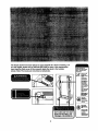
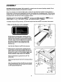
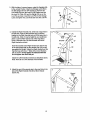
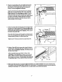
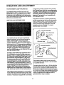
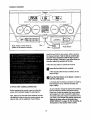
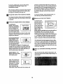
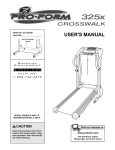
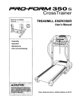
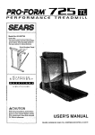
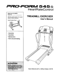
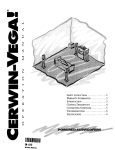
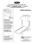
USER'S MANUAL
Model No. 831.293030
Serial No.
Ex
IE_ R C
EQUIPMENT
|e|li
_t
ire|
I _5 E
_
HELPLINE!
!-800-736-6879
Seam, Roebuck and Co.
Hoffman Estates, IL 60179
www.proform.com
new products, prizes,
fitness tips, and much morel
TABLE OF CONTENTS
IMPORTANT PRECAUTIONS ................................................................
BEFORE YOU BEGIN ......................................................................
ASSEMBLY ...............................................................................
OPERATION AND ADJUSTMENT .............................................................
HOW TO FOLD AND MOVE THE TREADMILL ..................................................
TROUBLESHOOTING .....................................................................
CONDITIONING GUIDELINES ...............................................................
ORDERING REPLACEMENT PARTS ..................................................
FULL 90 DAY WARRANTY ...........................................................
Note: An EXPLODED DRAWING and a PART LIST are attached in the center of this manual.
IMPORTANT
PRECAUTIONS
2
2
4
5
8
11
13
15
Back Cover
Back Cover
The decals shown have been placed on your treadmill. If a decal is missing, or if
it is not legible, please call our ton-free HELPLINE to order a free replacement
decal (see the front cover of this manual). Apply the decal in the location
shown. Note: The decals are not shown at actual size.
I
3
BEFORE YOU BEGIN
Thank you for selecting the revolutionary PROFORM ®
320x treadmill. The 320x treadmill combines advanced
technology with innovativedesign to help you get the
most from your exercise program in the convenience
and privacyof your home. And when you're not exercising,the unique320x treadmillcan be folded up, requidngloss than half the floor space of other treadmills.
Monday through Saturday, 7 a.m. until 7 p.m. Central
Time (excluding holidays). To help us assist you,
please note the productmodel number and serial number before calling. The model number of the treadmill
is 831.293030. The sedal number can be found on a
decal attached to the treadmill(see the front cover of
this manual for the location).
For your benefit, read this manual carefully before
using the treadmill. If you have additionalquestions,
please call our toll-free HELPLINE at 1-800-736-6879,
Before readingfurther, please review the drawing
below and familiadze yourselfwith the labeled parts.
Bookreck
Water BottleHolder
(Bottle not included)
Console
Storage Latch
Key/Clip
/_
Updght
Handrail
CircuitBreaker
Walking BeltFoot
\
RIGHT SIDE
CushionedWalking Platform
for maximum exercise comfort
BACK
Rear
Adjustment Bolts
4
ASSEMBLY
Assembly requires two persons. Set the treadmillin a cleared area and remove all packing materials. Do not
dispose of the packing matedals untilassembly is completed.
Note: The underside of the treadmillwalking belt is coated with high-performance lubricant. During shipping,a
small amount of lubricant may be transferred to the top of the walking belt or the shippingcarton. This is a normal
condition and does not affect treadmill performance. If there is lubricant on top of the walking belt, simply wipe off
the lubricant with a soft cloth and a mild, non-abrasive cleaner.
Assembly requires the included allen wrsnc==_es and your own phillips screwdriver (__,
rubber mallet _
,wire cutters _
,and nsedlenose pliers _BS_,
•
To identify small parts during assembly, use the PART IDENTIFICATION CHART in the center of this manual.
1. Make sure that the power cord is unplugged.
With the help of a second person, carefully raise the
Updghts (69) untilthe treadmill is in the position shown.
Insert one of the Extension Legs (63) into the treadmill
as shown. (Note: It may be helpfulto tip the Uprights as
you insert the ExtensionLeg.) Make sure that the
Warning Decal (62) is on the indicated side of the
Extension Leg.
63
Insert the otherExtensionLeg (63) in the same way.
2. With the help of a second person,carefully lower the
treadmillframe and then tip the Updghts(69) down as
shown. (Note: It may be helpfulto place your foot on an
Extension Leg [63] as you tip the Uprights.)Make sure
that the Extension Legs remain in the Uprights.
2
57-j_.."
58
Attach each Extension Leg (63) with two 3/4" Tek
Screws (58).
Attach four Base Pads (57) with 3/4" Tek Screws (58) as
shown.
Note: One replacement Base Pad (57) may be included.
If a Base Pad becomes worn and needs to be replaced,
use the replacement Base Pad.
5
I
57_
e_
/
58
3. With the help of a second person, raise the Uprights (69)
to the vertical Position.Attach the Storage Latch (36) to
the left Upright with two 3/4" Screws (2). Remove the
Lock Knob (30) from the Lock Pin (35). Make sure that
the Lock Pin Collar (33) and the Spring (32) are on the
Lock Pin as shown. Insertthe Lock Pin intothe Storage
Latch and tighten the Lock Knob back onto the Lock Pin.
4. Identifythe Right Handrail (72), which has a large hole in
the left side. Feed the Wire Harness (42) up into the
bracket on the Right Handrail and out of the large hole in
the left side. (Note: It may be helpfulto use needlenose
pliersto pull the Wire Hamess out of the large hole.)
Press a Handrail Cap (76) onto the lower end of the
Right Handrail as shown.
3
Large
Hole
38
Insert the bracket on the Right Handrail (72) into the top
of the right Upright (69) so the Handrail Cap (76) is resting against the Upright.Attach the Right Handrail and the
Handrail Cap with three 1" Bolts (37) and two Washers
(38) as shown. Firmly tighten the indicated Bolt but
do not tighten the other Bolt yet.
Attach the Left Handrail (not shown) as described above.
Note: There is not a wire harness on the left side.
5. Attach the end of the groundwire to the small hole in the
side of the Right Handrail (72) with a Silver Ground
Screw (75).
-76
Ground
Wire
75
6
6. Place the Console Base (47) on the Right Handrail (72)
and the Left Handrail (not shown). Attach the Console
Base with four 314"Screws (2) (onlytwo Screws are
shown). Do not overtighten the Screws.
6
I
47
Insertthe Wire Harness (42) through the two indicated
plasticties on the Console Base (47). Next, touch the
Right Handrail (72) to discharge any static. Plug the
widest connectoron the Wire Harness intothe widest
connector on the back of the Console (43). If the connector does not fit easily, rotate it and then connect it.
Plugthe otherconnector on the Wire Harnessintothe
otherconnector on the Console.
7. Insert the excess Wire Harness (42) intothe large hole in
the side of the Right Handrail (72). Securely tighten the
plastic ties on the bottom of the Console Base (47) to
prevent the Wire Harness from slipping. Then, cut off
the ends of the plasticties.
43
7
Ties
42 O_
Route the Wire Harness (42) through the indicatedopening in the Console Base (47). Attachthe Wire Cover to the
Console Base (47) with a 1/2" SilverScrew (48).
Tighten two 3/4" Screws (2) into the Console Base (47).
Ill\ "
8. Attach a Wheel (66) to the inner side of each Extension
Leg (63) with a Wheel Bolt(64) and a Wheel Nut (13) as
shown. Do not overtighten the Bolt. The Wheel should
be able to spinfreely.
Lift the treadmill frame (see HOW TO FOLD THE
TREADMILL FOR STORAGE on page 11), but do not
latch it. Make sure that the frame is centered between
the Handrails (not shown). Firmly tighten the boltsused
in assembly step 4. Then, lower the frame to the floor.
66
9. Make sure that all parts are property tightened before you use the treadmill. Note: Extra hardware may
be included. Keep the included allen wrenches in a secure place. The large allen wrench is used to adjustthe
walking belt (see page 14). To protectthe floor or carpet, place a mat under the treadmill.
OPERATION
AND ADJUSTMENT
THE PERFORMANT LUBE TM WALKING BELT
Your treadmill features a walking belt coated with
PERFORMANT LUBETM, a high-performance lubdcent.
IMPORTANT: Never apply silicone spray or other
substances to the walking belt or the walking platform. Such substances will deteriorate the walking
belt and cause excessive wear.
HOW TO PLUG IN THE POWER CORD
an equipment-groundingconductor and a grounding
plug. Plug the power cord into a surge suppressor,
and plug the surge suppressor Into an appropriate
outlet that is properly installed and grounded in
accordance with all local codes and ordinances.
Important: The treadmill is not compatible with
GFCl-equipped outlets.
This productis for use on a nominal 120-volt circuit,
and has a groundingplugthat looks like the plug illustrated in drawing 1 below. A temporary adapter that
lookslike the adapter illustratedin drawing 2 may be
used to connectthe surge suppressorto a 2-pole
receptacleas shown in drawing2 if a propedy
groundedoutlet is not available.
_Grounded
_? l_:::gu:dSi::
Your treadmill, like any other type of sophisticated
electronic equipment, can be sedously damaged by
sudden voltage changes in your home's power.
Voltage surges, spikes, and noise interferencecan
resultfrom weather conditionsor from other appliances
being turned on or off. To decrease the possibility of
your treadmill being damaged, always use a surge
suppressor with your treadmill (see drawing t at
the dght). To purchase a surge suppressor, see
your local SEARS dealer or call 1-800-366-7278 and
order part number 146148.
i
Usa only a single-outlet surge suppressor that is
UL 1449 listed as a transient voltage surge suppressor (TVSS). The surge suppressor must have a
UL suppressed voltage rating of 400 volts or less
and a minimum surge dissipation of 450 joules.
The surge suppressor must be electrically rated
for 120 volta AC and t5 amps. There must be a
monitoring light on the surge suppressor to indicate whether it is functioning propedy. Failure to
use a properly functioning surge suppressor could
result in damage to the control system of the
treadmill. If the control system is damaged, the
walking belt may change speed or stop unexpectedly, which may result in a fall and serious injury.
pPr::sor
unding
Grounded Outlet
[ "J
Outlet Box
Grounding Plug_
Groundod Outlet Box
Adapter
^
JLk'_,--_l
Surge _uppressor
Metal Screw
The temporary adapter should be used only untila
propedygroundedoutlet (drawing 1) can be installed
by a qualified electrician.
The green-coloreddgid ear, lug, or the like extending
from the adapter mustbe connected to a permanent
ground such as a properlygroundedoutlet box cover.
Whenever the adapter is used it must be held in place
by a metal screw. Some 2-pole receptacle outlet box
covers are not grounded. Contact a qualified electrician to determine if the outlet box cover is
grounded before using an adapter.
This product must be grounded. If it should malfunction or break down, groundingprovidesa path of least
resistancefor electric currentto reduce the dsk of electric shock. This productis equipped with a cord having
8
CONSOLE DIAGRAM
Displays
IJ9:SB
3.0.
I
Note: If there is a thin sheet of
Key--
_-7-'
plastic on the console,remove it.
Pulse
I
--
Sensor
Insert the key fully into the console.After a moment,
the displays will light.Test the clip by carefully takIng a few steps backward until the key Is pulled
from the console. If the key is not pulled from the
console, adjust the position of the clip.
Followthe steps below to operate the console.
_!
Insert the key fully into the console.
A few seconds after the key is inserted, the displayswill light.
B
Press the Start button orthe Speed L_button to
start the walking belt.
A moment after the button is pressed, the walking
belt will begin to move. Hold the handrailsand
begin walking.
STEP-BY-STEP CONSOLE OPERATION
As you exercise, change the speed of the walking
belt as desired by pressingthe Speed buttons.
Each time a button is pressed, the speed setting
will change by 0.1 mph; if a buttonis held down,
the speed settingwill change in incrementsof 0.5
mph. Note: The console can display speed and
distance in either miles or kilometers (see
SPEED DISPLAY on page 10). For simplicity, all
instructions in this section refer to miles.
Before operating the console, make sure that the
power cord is propedyplugged in (see page 8).
Next, stand on the foot railsof the treadmill. Find the
clipattached to the key (see the drawing above), and
slidethe clip ontothe waistband of your clothes.
9
Note: During the first few minutesthat the treadmill
is used, inspectthe alignmentof the walking belt,
and align it if necessary (see page 14).
continue to hold the Stop button for a moment. An
"E"for Englishmiles or an "M"for metric kilometers
willappear in the Fat Calories/Calories/Pulsedisplay. Press the Speed A buttonto change the unit
of measurement. When the desired unitof measurement is selected, remove the key and then
reinsert it.
Change the incline of the treadmill as desired.
To reset the displays,press the Stop button, remove the key, and then reinsert the key.
To stop the walking belt, press the Stop button.
The elapsed time will begin to flash in the
Time/Distance display.
B
To change the inclineof the treadmill, press either
of the Inclinebuttons untilthe desired inclinelevel
is reached.
B
!_','_Measure your heart rate if desired.
To measure your
heart rate, stand on
the foot railsand
place yourthumb
on the pulsesensor.
Do not press too
hard, or the circulation in your
thumb will be restricted and your pulse will not
be detected. After a few seconds,the heartshaped indicatorin the Fat Calories/Calories/
Pulse displaywill begin to flash, one or two dashes
(--) will appear, and then your heart rate will be
shown. Hold yourthumb on the pulsesenser for
about 15 secondsfor the most accurate reading.
Follow your progress with the three displays.
TimelDistance
Mode Indicator
display--This display
shows the elapsed time
and the distance that
you have walked or run.
TIME
DISTANCE
The display will change
from one number to the
other every few seconds, as shown by the mode
indicators.When the Stop button is pressed, the
elapsed time will flash.
Fat CalorieslCalories/
Pulse display--This
display shows the approximate numbers of
fat calories and calories
you have bumed (see
FAT BURNING on page 15). The display will
change from one number to the other every few
seconds, as shown by the mode indicators.The
display will also show your heart rate when you
use the pulse sensor (see step 5).
If the displayedheart rate appears to be too high
or too low, or if your heart rate is not displayed, lift
yourthumb offthe pulse sensorfor a few seconds.
Then, place yourthumb on the pulsesensoras describedabove. Remember to stand stillwhile measuringyour heart rate.
r_When
key.
Speed display--This
display shows the speed
of the walking belt
you are finished exercising, remove the
Step onto the foot rails, press the Stop button, and
remove the key from the console. Keep the key in a
sect.Ira place.
Note: The console can
display speed and distance in either miles or
FAT OALS*
PULSE
kilometers.To change
the unit of measurement, hold down the
Stop button, insertthe key intothe console, and
[E ]
I
10
HOW TO FOLD AND MOVE THE TREADMILL
HOW TO FOLD THE TREADMILL FOR STORAGE
Before folding the treadmill, unplug the power cord. CAUTION:
You must be able to safely lift 45 pounds (20 kg) in order to
raise, lower, or move the treadmill.
1. Hold the treadmill with your hands in the locations shown at
the right.To decrease the possibility of injury, bend your
legs and keep your back straight. As you raise the treedmill, make sure to lift with your legs rather than your
back. Raise the treadmill about halfway to the vertical position.
2. Move your right hand to the positionshown and hold the
treadmill firmly. Using your left hand, pull the latch knob to
the left and hold it. Raise the treadmill until the latch pin is
aligned with the square hole between the frame and the foot
rail. Slowly release the latch knob and insert the latch pin into
the hole. Make sure that the frame is securely held by the
latch pin.
To protect the floor or carpet from damage, place a mat
under the treadmill. Keep the treadmill out of direct sunlight. Do not leave the treadmill in the storage position in
temperatures above 85 ° Fahrenheit.
Engaged
HOW TO MOVE THE TREADMILL
Before movingthe treadmill, convert the treadmill to the storage
positionas descdbed above. Make sure that the frame is securely held by the latch pin.
1. Hold the upper ends of the handrails. Place one foot on the
base as shown.
2. Tilt the treadmill back until it rollsfreely on the front wheels.
Carefully move the treadmill to the desired location.To reduce the risk of injury, use extreme caution while moving the treadmill. Do not move the treadmill over an uneven surface.
•Base
3. Place one foot on the base, and carefully lower the treadmill
until it is resting in the storage position.
11
FrontWheels
HOW TO LOWER THE TREADMILL FOR USE
1. Hold the upper end of the treadmillwith your right hand as
shown. Using your left hand, pull the latch knob to the left
and hold it. Pivot the treadmilldown until the frame is past
the latch pin. Slowly release the latch knob.
Engaged
2. Hold the treadmill firmlywith both hands, and lower the treadmillto the floor. Do not drop the treadmill frame to the
floor. To decrease the possibility of injury, bend your
legs and keep your back straight.
12
TROUBLESHOOTING
Most treadmill problems can be solved by following the simple steps below. Find the symptom that
applies, and follow the steps listed. If further assistance is needed, call our toll-free HELPLINE at
1-800-736-6879, Monday through Saturday, 7 a.m. until 7 p.m. Central Time (excluding holidays).
PROBLEM: The power does not tum on
SOLUTION: a. Make sure that the power cord is plugged into a surge suppressor,and that the surge suppressor
is plugged into a propedygroundedoutlet (see page 8). Use only a single-outletsurge suppressor
that meets all of the specificationsdescribedon page 8. Important:The treadmillis not compatible
with GFCI-equipped outlets.
b. After the power cord has been pluggedin, make sure that the key is fully insertedintothe console.
c. Check the circuit breaker located on the treadmill
frame near the power cord. If the switch protrudes
as shown, the circuitbreaker has tripped. To reset
the circuit breaker, wait for five minutes and then
press the switch back in.
PROBLEM:
The power turns offduring
Reset[_
Tripped
use
SOLUTION: a. Check the circuitbreaker located on the treadmill frame near the power cord (see the drawing
above). If the circuit breaker has tripped, wait for five minutes and then press the switch back in.
b. Make sure that the power cord is plugged in. If the power cord is plugged in, unplug it, wait for
five minutes, and then plug it back in.
c. Remove the key from the console. Reinsert the key fully intothe console.
d. If the treadmillstillwill not run, please call our toll-free HELPLINE.
PROBLEM: The displays of the console do not function properly
SOLUTION: a. Remove the key from the console and UNPLUG THE
POWER CORD. Remove the two 3/4" Screws (2)
from the hood, and carefully pivotthe Hood (1) off.
Locate the Reed Switch (10) and the Magnet (18) on
the left side of the Pulley (17)oTurn the Pulley untilthe
Magnet is aligned with the Reed Switch. Make sure
that the gap between the Magnet and the Reed
Switch Is about 1/8". If necessary, loosenthe Screw
(56) and move the Reed Switch slightly. Retightenthe
Screw. Re-attach the Hood, and runthe treadmillfor a
few minutes to check for a correctspeed reading.
13
118"-10_
66
Top
View
17
PROBLEM: The walking belt slows when walked on
SOLUTION: a. Use onlya single-outletsurge suppressorthat meets all of the specificationsdescribed on page 8.
b_
If the walking belt is overtightened,treadmill performanca may decrease and the walking belt may become damaged. Remove the key and UNPLUG THE
POWER CORD. Using the allen wrench, turn both
rear rolleradjustment bolts counterclockwise. 1/4 of a
turn. When the walking bolt is properly tightened, you
should be able to lift each side of the walking belt 2 to
3 inches off the walking platform. Be careful to keep
the walking belt centered. Plug in the power cord, insert the key, and run the treadmill for a few minutes.
Repeat until the walking belt is propedy tightened.
b
Rear Roller Adjustment Bolts
c. If the walking belt still slows when walked on, please call our toll-free HELPLINE.
PROBLEM: The walking belt is off-center or slips when walked on
SOLUTION: a. If the walking belt is off-center, first remove the key
and UNPLUG THE POWER CORD. If the walking
belt has shifted to the left, use the allen wrenchto
tum the left rear rollerbolt clockwise1/2 of s turn; if
the walking belt has shifted to the right, tum the
bolt countemlockwise1/2 of a turn. Be careful not to
overtightenthe walking belt. Plugin the power cord,
insertthe key, and run the treadmillfor a few minutes.
Repeat untilthe walking belt is cantered.
b.
If the walking belt slipswhen walked on, first remove
the key and UNPLUG THE POWER CORD. Using
the allen wrench, turn bothrear rollerboltsclockwise,
1/4 of a turn. When the walking belt is correctly tightened, you shouldbe able to lift each side of the walking belt 2 to 3 inches offthe walking platform.Be
careful to keep the walking belt cantered. Plug in the
power cord, insertthe key, and carefully walk on the
treadmill for a few minutes. Repeat until the walking
belt is propedytightened.
14
b
CONDITIONING
GUIDELINES
ergy. Only after the first few minutesdoes your body
begin to use stored fat calories for energy. If your goal
is to burn fat, adjustthe speed and incline of the treadmilluntil your heart rate is near the lowest number in
yourtraining zone.
For maximum fat buming, adjust the speed and incline
of the treadmill untilyour heart rate is near the middle
number in yourtraining zone.
Aerobic Exercise
The followingguidelines will help you to plan your exemise program. For more detailed exercise information, obtain a reputable book or consult your physician.
EXERCISE INTENSITY
Whether your goal is to burn fat or to strengthenyour
cardiovascularsystem, the key to achievingthe
desired resultsis to exercise with the proper intensity.
The proper intensitylevel can be found by usingyour
heart rate as a guide. The chart below shows recommended heart rates for fat burningand aerobicexercise.
HEART
RATE TRAINING
FATBURN
_25
AOe¸ 20
ZONES
1_0
30
115
40
110
50
1B5
60
95
70
90
80
To find the proper heart rate for you, first find your age
near the bottom of the chart (ages are rounded off to
the nearest ten years). Next, find the three numbers
above your age. The three numbers define your "training zone." The lower two numbers are recommended
heart rates for fat burning;the highernumber is the
recommended heart rate for aerobic exercise.
To measure your heart rate during exercise, use the
pulse sensor. If your heart rate is too high or too low,
adjustthe speed and incline of the treadmill.
Fat Burning
To burn fat effectively, you must exercise at a relatively
low intensity level for a sustained pedod of time.
Dudng the first few minutes of exercise, your body
uses easily accessible carbohydrate calories for en-
If yourgoal is to strengthenyour cardiovascularsystem, your exercise must be "aerobic."Aerobicexercise
is activitythat requires large amounts of oxygen for
prolonged periodsof time. This increases the demand
on the heart to pump bloodto the muscles,and on the
lungsto oxygenate the blood. For aerobic exercise,
adjustthe speed and inclineof the treadmilluntil your
heart rate is near the highest number in your training
zone.
WORKOUT GUIDELINES
Each workout shouldincludethe followingthree parts:
A Warm-up--Start each workout with 5 to 10 minutes
of stretchingand light exercise. A properwarm-up increases your body temperature, heart rate and circulation in preparation for exercise.
Training Zone Exercise--After warming up, increase
the intensityof your exercise until your pulse is in your
trainingzone for 20 to 60 minutes. (Dudngthe firstfew
weeks of your exercise program, do not keep your
pulse in your training zone for longerthan 20 minutes.)
Breathe regulady and deeply as you exercise_never
hold your breath.
A Cool-down--Finish each workoutwith 5 to 10 minutes of stretchingto cool down. This will increase the
flexibilityof your musclesand will help prevent postexercise problems.
EXERCISE FREQUENCY
To maintain or improve your condition,completethree
workoutseach week, with at least one day of rest betwean workouts.After a few months, you may complete up to five workouts each week if desired.The key
to success is to make exercise a regular and enjoyable
part of your everyday life.
15
PART IDENTIFICATION
CHART
Remove this chart and use it to identify small parts during assembly. Save
this chart and the EXPLODED DRAWING/PART
LIST for future reference,
Silver Ground
3/4" Screw (2)-8
Screw (75)-1
3/4" Tek Screw
(58)-8
1/2" Silver Screw (48)-1
1" Bolt(37)-6
Washer (38)--4
Wheel Bolt (64)-2
Wheel Nut (13)-2
PART LISTmModel
Key
No.
1
2
3
4
5
6
7
8
9*
10
11
12
13
14
15
16
17
18
19
20
21
22
23
24
25
26
27
28
29
30
31"
32
33
34
35
36
37
38
39
40
41
42
43
44
45
46
47
48
49
50
51
52
53
54
55
56
57
58
Qty.
1
15
1
1
5
1
1
1
1
1
1
2
5
2
4
1
1
1
1
2
1
2
1
4
1
6
1
1
1
1
1
1
1
1
1
1
6
6
2
1
1
1
1
1
1
1
1
1
2
1
1
1
2
2
2
2
4
11
No. 831.293030
Description
Hood
3/4" Screw
Motor Belt
Motor Tension Bolt
Flat Washer
Motor Star Washer
Flywheel
Motor
Motor Assembly
Reed Switch
Latch Warning Decal
Frame Spacer
Frame Pivot Nut/Motor Nut
Frame Pivot Bolt
Walking Platform Screw
Left Foot Rail
Front RoUer/Puney
Magnet
Motor Pivot Bolt
Motor Bracket Bolt
Right Foot Rail Endcap
Belly Pan Clip
Front Roller Adjustment Bolt
Plastic Stand,off
ElectronicsBracket
ElectronicsScrew
Power Board
Motor Tension Nut
Choke
Lock Knob
Lock Knob Assembly
Spring
Lock Pin Collar
Lock Pin Clip
Lock Pin
Storage Latch
1" Bolt
Washer
CrossbarScrew
Crossbar
5/32" Allen Wrench
Wire Harness
Console
Wire Cover
Waming Decal
Bookrack
Console Base
1/2" Silver Screw
112"Console Screw
Key/Clip
Incline Motor
Incline Bracket
Incline Motor Bolt
Clevis Pin
Cotter Pin
Ground Screw
Base Pad
3/4" Tek Screw
R1102A
Key
No.
Qty.
59
60
61"
62
63
64
65
66
67
68
69
70
71
72
73
74
75
76
77
78
79
80
81
82
83
84
85
86
87
88
89
90
91
92
93
94
95
96
97
98
99
100
101
102
103
104
105
#
#
#
#
#
#
#
#
1
1
2
2
2
2
4
2
1
4
1
1
1
1
4
1
1
2
4
1
1
1
1
2
4
4
2
1
4
2
2
1
1
2
1
1
1
1
1
1
1
1
2
12
1
1
1
1
1
1
1
1
1
1
1
Description
Controller
Lift Frame
ExtensionLeg Assembly
Warning Decal
Extension Leg
3 112"Bolt
Base Endcap
Wheel
Waming Decal
8" Cable Tie
Base
Grommet
Left Handrail
Right Handrail
Cage Nut
Left Foot Rail Endcap
1/2" Silver Ground Screw
Handrail Cap
Belly Pan Screw
CircuitBreaker
Power Cord
Power Cord Grommet
Belly Pan
Belt Guide
Belt Guide Screw
Plastic Fastener
IsolatorCushion
Frame
Releasable Tie
Clamp Screw
Cable Tie Clamp
GroundWire
Right Rear Endcap Pad
Rear Roller Adjustable Bolt
Right Rear Endcap
Allen Wrench
Left Rear Endcap
Walking Belt
Walking Platform
Right Foot Rail
Left Rear Endcap Pad
Rear Roller
Plastic Tie
Rear Endcap Screw
Motor Mount Bracket
InclineMotor Wire
Motor ControllerWire
8" Red Wire, M/F
4" Red Wire, M/F
8" Blue Wire, 2F
4" Blue Wire, 2F
4" White Wire, M/F
8" White Wire, 2F
8"Green Wire, 2 Ring
User's Manual
* Includes all parts shown in the box
# These parts are not illustrated
4O
4
5
32
42
2
26
CJ
34
35
2
I0
o_
13
54
14
69
73
95
73
13
65
B1
SEARS
The model number and sedal number of your PROFORrvP 320x
treadmill are listedon a decal attached to the frame. See the front
cover of this manual to find the locationof the decal.
Model No. 831.293030
QUESTIONS?
All replacement parts are available for immediate purchase or
special order when you visit your nearest SEARS Service Center.
To request service or to order parts by telephone, call the toll-free
numbers listed at the left.
If you find that:
• you need help assembling or
operating the PROFORM 320x
treadmill
• a part is missing
When requesting help or service, or orderingparts, please be
prepared to provide the following information:
• The NAME OF THE PRODUCT (PROFORM ®320x treadmill)
• or you need to schedule repair
service
call our toll-free HELPLINE
1-800-736-6879
Monday-Saturday, 7 am-7 pm
Central Time (excluding holidays)
• The MODEL NUMBER OF THE PRODUCT (831.293030)
• The KEY NUMBER AND DESCRIPTION OF THE PART (see the
EXPLODED DRAWING end PART LIST in the center of this
manual)
REPLACEMENT
PARTS
If parts become worn and need
to be replaced, call the following
toll-free number
t-800-FON-PART
(1-800-366-7278)
FULL 90 DAY WARRANTY
For 90 days from the date of purchase, if failure occursdue to defect in matadal or workmanshipin this
SEARS TREADMILL EXERCISER, contact the nearest SEARS Service Center throughout the United
States and SEARS will repair or replacethe TREADMILL EXERCISER, free of charge.
This warrantydoes not applywhen the TREADMILL EXERCISER is used commerciallyor for rental purposes.
This warranty gives you specificlegal rights, and you may also have other dghts which vary from state
to state.
Sears, Roebuck and Co., Dept. 817WA, Hoffman Estates, IL 60179
Part No. 189304 R1102A
Printed in USA © 2002 Sears, Roebuck and Co.