1
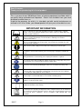
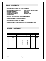
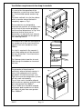
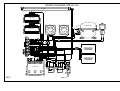
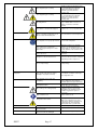
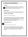
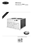
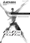
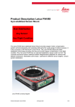
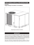
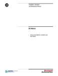
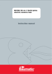
User and Installation Instructions
Seal Refrigerated Merchandisers
C6R/75, C6R/100, C6R/105, C6R/125,
C6R/130, D6R/100, D6R/125, D5R/100,
D5R/125, D3R/100
IS517
Page 1
Dear Customer,
Thank you for purchasing this Lincat product.
This is just one of over 300 different items of catering equipment available which is
constantly being extended and improved. Details are available from your local
distributor or direct from us.
Used for the purposes for which it is intended, and with careful maintenance as
outlined in this User Guide, your Lincat product will give years of trouble free use.
IMPORTANT INFORMATION
Please read all of the safety and operating instructions carefully before using this
product. Please pay particular attention to all sections of this User Guide that carry
warning symbols and notices.
This is a Warning symbol. This symbol is used throughout the user guide whenever
there is a risk of personal injury. Ensure that these warnings are read and
understood at all times.
This is a Caution symbol. This symbol is used throughout the User Guide whenever
there is a risk damaging your Lincat product. Ensure that these warnings are read
and understood at all times.
Make sure the power supply is turned off before making any electrical repairs.
To minimise shock and fire hazards, please do not plug or unplug the unit with wet
hands.
During maintenance and cleaning, please unplug the unit where required.
Care must be taken when handling or working on the unit as sharp edges may cause
personal injury, we recommend the wearing of suitable PPE.
Ensure the correct moving and lifting procedures are used when relocating a unit.
Do NOT use abrasive cleaning products, only those that are recommended. Never
scour any parts of the refrigerator. Scouring pads or chemicals may cause damage
by scratching or dulling polished surface finishes.
Failure to keep the condenser clean may cause premature failure of the
motor/compressor, which will NOT be covered under warranty policy.
Please ensure the appropriate use of safety aids or Personnel Protective Equipment
(PPE) are used for you own safety.
This is a Note symbol. This symbol is used throughout the User Guide to provide
additional information, hints and tips.
DISPOSAL REQUIRMENT
If not disposed of properly all refrigerators have components that can be harmful to
the environment. All old refrigerators must be disposed of by appropriately registered
and licensed waste contractors, and in accordance with national laws and
regulations.
IS517
Page 2
CONTENTS
Contents
Page
Safety instructions………………………………………………………4
Product specification………………………………………………….. 5
Features………………………………………………………………….. 5
Technical specification…………………………………………………5
Pack contents…………………………………………………….………6
Spare parts list………………………………………………………….. 6
Installation……………………………………………………………….. 7
Note to installer...............................……………………………. 7
Inspection.............................…………………………….……... 7
Handling.................................................................................. 7
General........................................................……………………7
Connecting to the electricity ...........................……………….7-8
Warning .......................................................……………………8
User Maintenance .......................................……………………8
Defrosting.....................................................……………………8
Warning........................................................……………………8
Loading.........................................................……………………8
Installation Instruction for C6R-U ..…………………..……………….9
Details of C6R-U cabinets.... .............…………………..…………….10
Details of cut-out for refrigeration module ..……….... ...…………11
Ventilation requirement for counter top models………..... …...…12
Wiring Diagrams..……................ ……………..……………….13-14-15
Troubleshooting...............…………………..……... ………….16-17-18
Operating instructions………………………………………………. .19
Cabinet Controls..................................………………………..19
Loading................................................………………………..19
Cleaning and maintenance………………………….... …………….20
Cleaning the condenser………………………………………..20
Replacing the light .....…………………………………………..20
Service information…………………………………………………….21
Conditions of guarantee…..…………………………………….……21
.
.
.
.
.
.
.
./
USE OF THE REFRIGERATED MERCHANDISERS
The Refrigerated Merchandisers are intended to be used on counter tops to
display pre-chilled food product.
IS517
Page 3
SAFETY INSTRUCTIONS
WARNING!
Basic safety precautions, including the following, should be
followed to reduce the risk of personal injury and/or damage to
the cabinet. Make sure you have fully read these instructions
before installing and switching on. Keep this User Guide in a safe
place for future reference for you and your staff.
Do not clean the unit with a water jet.
REMOVAL OF PACKAGING
Remove any external packaging. If using a sharp instrument take
care to avoid contact with the product inside.
In the interest of hygiene, you should clean the product after
unpacking and ensure all plastic coatings are removed before use.
This unit is heavy. Be aware of the risks when lifting or
moving it. Always lift the cabinet using the base or lower frame, do
not lift with any other part. Do not pull the unit across your work
surface as it may make a mark.
The cabinet relies on the circulation of cold air, which must pass through
and around the shelves. Ensure circulation is not obstructed by food
product blocking the internal vents.
GENERAL
Do not try to modify this product.
Ensure that the electrical supply cable is not damaged.
If the supply cable is damaged, it should be replaced by Lincat Ltd or suitably
qualified persons, in order to avoid a hazard.
IS517
Page 4
PRODUCT SPECIFICATION
650 Range Refrigerated Merchandiser – C6R/75, C6R/100, C6R/105,
C6R/125, C6R/130
D6R/100, D6R/125
500 Range Refrigerated Merchandiser – D5R/100, D5R/125
350 Range Refrigerated Merchandiser – D3R/100
FEATURES
Fan-assisted refrigeration
Double glazed glass (flat panels)
Electronic control
Hot gas automatic defrost
Sliding rear doors (double glazed)
Independently switchable light
Adjustable shelf positions (back
service models only)
230 Volt, 50 Hz, single phase
TECHNICAL SPECIFICATION
Model
Max. Operating
Temperature
Internal volume
Internal dims
Width
Depth
Height
Power Rating
Weight
Refrigerant
D3R/100
D5R/125
D6R/75
D6R/100
D6R/125
O
C
25
litres
85.8
127.3
172.2
226.6
306.4
386.2
cm 710x310x390 710x460x390 960x460x390 710x570x560 960x570x560 1210x570x560
mm
1000
1000
1250
750
1000
1250
mm
350
500
500
650
650
650
mm
575
575
575
965
965
965
watt
393
602
621
602
717
729
kg
68
84
100
95
123
149.5
R404a
Model
Max. Operating
Temperature
Internal volume
Internal dims
Width
Depth
Height
Power Rating
Weight
Refrigerant
IS517
D5R/100
C6R/75
C6R/100
O
C6R/105
C6R/125
C6R/130
C
25
litres
226.6
306.4
226.6
386.2
306.4
cm 710x570x560 960x570x560 710x570x560 1210x570x560 960x570x560
mm
750
1000
1050
1250
1300
mm
650
650
650
650
650
mm
755
755
755
755
755
watt
602
717
604
729
717
kg
89.5
117
105
137.5
112.2
R404a
Page 5
PACK CONTENTS
C6R/105, C6R/130, D6R/100, D6R/125 Models
Refrigerated Merchandiser (with
cable and 13amp plug)
2 x chrome-plated shelves
2 x removable base panels
2 x sliding doors
3mm Allen key (for shelf height
adjustment)
User Guide
Guarantee card
C6R/75U, C6R/100U, C6R/125U Drop-in Models
As above, plus drop-in refrigeration module
D5R/100, D5R/125, D3R/100 Models
As above, except 1 x chrome plated shelf and removable base plate.
SPARE PARTS LIST
Model
Compressor Light
LA01
LA01
LA05
LA01
LA05
LA05
LA01
LA05
LA01
LA05
LA05
EC15
S/R0181
All Models
IS517
CR08
CR08
CR07
CR08
CR07
CR07
CR08
CR07
CR08
CR07
CR07
All Models
D3R/100
D5R/100
D5R/125
D6R/75
D6R/100
D6R/125
C6R/75
C6R/100
C6R/105
C6R/125
C6R/130
Components
Controller Evaporator Condenser Shelf
fan
Fan Motor
Page 6
FA109
FA109
FA109
FA109
FA109
FA109
FA109
FA109
FA109
FA109
FA109
SH93
SH91
SH92
SH97
SH98
SH99
SH97
SH98
SH97
SH99
SH98
INSTALLATION
All models (For C6R/75U,C6R/100U,C6R/125U Models see additional instructions)
Note to installer
Please follow this instruction carefully. Only if the cabinet is correctly installed
will it give the best possible performance and reliability. Please pay particular
attention to the User maintenance section of this guide that the controller must
be left on the factory setting. There are also clear guidelines stating that the grill
on cabinet must not be blocked at any time and condenser must be cleaned
every 3 months. There are no user serviceable parts inside the refrigerated
compartment.
Inspection
On receipt, unpack the carefully and inspect for any superficial damage that
may have been sustained in transit. Record the nature of any damage on the
Carrier’s Delivery Note and at the same time inform your supplier.
Handling
Important: Keep the cabinet vertical and on its base, if the cabinet is tipped onto
its back, front or sides allow it to stand back on its base for at least 2 hours
before switching ON.
Ensure the cabinet is installed on a sound, level work surface, observing
requirements for ventilation as detailed on pages 10,11 & 12.Do not install this
cabinet close to any source of heat which may result in operating conditions
exceeding its design limits. Locations close to sources of moisture or steam will
cause excessive condensation on the outer surfaces of the cabinet and must be
avoided.
Ambient temperature range; minimum 18oC, maximum 25oCMaximum relative
humidity 60%.
General
Installation must only be carried out by a suitable trained person and comply
with national and local codes for connection to electrical supply. The cabinet
must be earthed... the earthing of the installation a safety standard,
which is enforced by law. Do not switch on the unit the installation has
been completed.
Connecting to the electricity supply
The cabinet is completely factory wired and only needs to be connected to a
suitable power point (socket).It are recommended that the mains electricity
supply is protected by an RCCB (Residual current circuit breaker). Cabinets are
supplied with 2 metres of cable and should be connected to an earthed,
switched, 13 amp 230Volts socket which should be easily accessible for
isolation of the cabinet.
The socket should be installed in accordance with current I.E.E regulations. If in
doubt consult a qualified electrician. The 1989 Electricity at work Regulation
requires periodic testing of electrical equipment and should be carried out by a
competent person.
The cabinet are designed for indoor use only in ambient temperature between
minimum 18oC, maximum 32oC.The cabinet must be positioned on a flat level
surface. To reduce energy consumption position the cabinet in a well ventilated
location, away from sources of heat. It should not be exposed to water spillage.
Spray steam or high humidity. Failure to do so may reduce the efficiency of the
cabinet and increase the frequency of maintenance required. Particular
attention should be paid to airflow restriction into and out of the refrigeration
system, this is very important for the cabinet to operate efficiently.
IS517
Page 7
Ensure that the voltage of your electricity supply corresponds to the serial plate
details. The product is supplied with a 13 Amp plug. To replace the plug, follow
these instructions:
•
•
•
green and yellow wire to 'E' or (Earth)
blue wire to 'N' (Neutral)
brown wire to 'L' (Live)
For safety regulations, the plug must always be accessible.
THIS APPLIANCE MUST BE EARTHED
Warning
Under no circumstances must the power supply be switched ON and OFF in
quick succession over a short period. To do this could result in serious damage
to the compressor, causing failure of refrigeration system. Having completed the
electrical connection, the cabinet can be switched 'On' at the mains. When the
unit is first switched ‘ON ‘you will hear condenser fan motors running and the
compressor, evaporator fan will come ‘On’ when the evaporator is cooled to
correct temperature. The temperature inside the cabinet is controlled by mean
of electronic controller, which is factory set and should not need any
adjustment. The cabinets are designed to be left ON at all times, like a domestic
refrigerator Ensure the door of the cabinet remain closed when not being used.
Failure to do so will reduce the efficiency of the refrigeration system and may
cause excess condensation or ice build up on the evaporator.
User Maintenance
Due to electrical regulation only a very limited amount of user maintenance
work can be carried out. There are no user serviceable parts inside the
refrigeration compartment.
Please note- No cleaning or maintenance work should be attempted until
the cabinet is switched off and the plug removed from the socket.
Only use genuine Lincat spares. All parts numbers are listed on the Spares list
on page 6 for easy ordering when required.
Defrosting
The Seal Refrigerated Merchandises are fitted with an automatic defrost
function ensuring the cooling heat exchanger remains free from ice. The
condensate water is automatically dispersed using the heat from the
refrigeration unit.
Loading
When loaded ensure that air can circulate around / through store products.
Cover all foods and separate raw and cooked food. Do not allow items to
overhang the edges of the shelves.
IS517
Page 8
INSTALLATION INSTRUCTIONS FOR C6R/75U, C6R/100U,
C6R/125U DROP-IN MODELS
Refer to the information on page 4 before proceeding.
The cabinet is not connected to the refrigeration module during transit. Remove
the doors, shelves and base panels from the cabinet and lift this from the pallet
first to separate the two parts of the appliance.
Prepare the counter taking note of the ventilation requirements on page 11.
Cut a hole in the counter top according to the diagram (2) on page 10. Lift the
refrigeration module onto the counter top so that the electrical supply cable is
on the customer’s side. Lower through the hole and ensure that the cable is not
trapped.
Carefully lower the cabinet over the refrigeration module and onto the counter
top ensuring the cables are not trapped. The plinth around the base of the
cabinet must be fully supported by the counter top beneath; no part of this plinth
should be allowed to overhang the counter top.
Open the evaporator box back lid, connect cables to terminal blocks (see
diagram below)
CH 1
CABINET
EARTH
CH 2
BLUE TO
LIGHT
BROWN TO
LIGHT
BLUE FROM
BROWN FROM
LIGHT SWITCH LIGHT SWITCH
EARTH
WIRES
TERMINAL
BRACKET
LIGHT TERMINAL
BLOCK
EARTH
TERMINALS
IS517
BLUE FROM
TERMINAL
TERMINAL
LID
Using the screw supplied secure
the terminal lid and hinged lid.
Replace base panels, shelves
and doors.
The cabinet is now ready for use
Refer to operating instruction on
page 19.
BROWN FROM
TERMINAL
Page 9
FRAME HEATERS
TERMINAL BLOCK
Details of the base section and cabinet (1)
152
47
75
196
279
390
279
C/L
390
558
65
Details of cut-out for refrigeration module (2)
210
25
420
BACK OF COUNTER / FOOD SERVICE SIDE
565
FRONT OF COUNTER / CUSTOMER SIDE
750750
Models
1000
1000
Models
1250
1250
Models
IS517
Page 10
50
Ventilation requirements for drop in models
It is crucial for the operation of the
refrigeration system that a free flow of
air is maintained around condensing
unit.
The ideal method is to site the cabinet
within a counter where the back is
completely open as Fig 1.
Fig 1
CO
LD
These cabinets are designed to
eliminate the need for an unsightly vent
on the front of the counter providing
that the critical dimensions in Fig 2 are
observed and no there are no
obstructions in front of the air exhaust
that may be deflected into the path of
the incoming cold air.
WA
RM
WA
RM
CO
LD
AIR
EN
TE
RS
AI R
AIR
EX
ITS
AIR
EN
TE
RS
EX
ITS
Fig 2
The dimension X from the front grille of
the condenser to the inner face of the
counter front must not be less than
200mm.
If a shelf is required in the counter it
must allow adequate air flow beneath
the unit, dimension Y must be no less
than 200mm.
WARM AIR EXITS
X
Y
Fig 2 demonstrates how the air must
flow through the condenser to extract
the heat.
To guarantee a flow of cool air
particularly where the back counter is
warm, then adequate vents can be
provided in the front of counter (see
Fig3) to ensure the refrigeration system
will only work satisfactorily.
The air inlet vents should be aligned
with condenser aperture and have total
free area greater than 900cm2.
The air outlet also should be aligned
with power pack condenser air outlet
grill and have total free area greater
than 1000cm2.
IS517
Page 11
Fig 3
AMBIE
NT AIR
IN
Ventilation requirements for counter top models
Minimum distance of vents from any adjacent wall or surface
500mm
D6R/75B & S
D6R/100B & S
D6R/125B & S
200mm
500mm
C6R/105BL & BR
C6R/105SL & SR
C6R/130BL & BR
C6R/130SL & SR
200mm
500mm
D5R/100B & S
D5R/125B & S
D3R/100
IS517
200mm
Page 12
WIRING DIAGRAM C6R75-100-125-U
LIGHT
EVAPORATOR
FAN
EVAPORATOR
FAN
CONDENSER
COMPRESSOR
HOT GAS
SOLONOID
C
OR
BR
S
R
1
2
GR
BL
BR
GR
BK
BL
BL
BR
BR
GR
GR
GR
FRAME HEATER
GR
BK
BL
GR
BL
OR
BR
BL
BR
BL
12
11 10
9
8
7
6
5
4
3
2
FRAME HEATER
BL
BR
1
G
BL
CONTROLLER
BR
G
MAIN
SWITCH
IS517
LIGHT
SWITCH
Page 13
BL
BR
BL
WIRING DIAGRAM C6R105-130
LIGHT
CONDENSER
COMPRESSOR
GR
EVAPORATOR
FAN
CONDENSER
EVAPORATOR
FAN
OR
C
BL
GR
S
R
1
2
BR
BR
BL
OR
GR
GR
BL
BK
BK
BK
BK
BL
FRAME HEATER
BR
BR
BR
BL
BL
FRAME HEATER
BL
BL
12
11
10
9
8
7
6
5
4
3
2
BL
BL
BR
1
BR
GR
BR
CONTROLLER
LIGHT
SWITCH
IS517
MAIN
SWITCH
Page 14
HOT GAS
SOLONOID
WIRING DIAGRAM D6R75-100-125
LIGHT
HOT GAS
SOLONOID
EVAPORATOR FAN
EVAPORATOR FAN
G
BL
COPMPRESSOR
G
G
G
BR
BR
C
OR
S
R
1
2
G
BL
BR
BL
BL
BL
BL
BL
G
OR
BR
BR
CABINET PROBE
SUCTION PROBE
BR
12 11
10
9
8
7
6
5
4
3
2
BL
1
CONTROLLER
LIGHT SW
MAIN SW
CONDENSER
BR
BR
BR
BL
FRAME HEATER
BL
BR
G
IS517
Page 15
BL
Troubleshooting
Problem
Compressor will not start
Possible Cause
No voltage in socket
Electrical conductor or wires may be
cut
Use voltmeter to check
Use ohmmeter to check for continuity
Defective electrical component:
controller, relay, thermal protector etc
Replace defective component
Compressor motor has a winding
open or shorted
The temperature is too cold
Change compressor
Temperature control contacts are
open
Incorrect wiring
Fuse blown or circuit breaker tripped.
Mains Power cable unplugged
Controller set too high
Cabinet in defrost cycle
Replace the controller
Controller is set at a very cold
position
Control contacts are stuck closed
IS517
Measure ohmic resistance of main
and auxiliary winding using
ohmmeter. Compare with correct
values
Change compressor
Compressor stuck
Controller does not disconnect the
condensing unit
The temperature is not cold
enough
Solution
Defective or incorrect temperature
controller
Controller is set at a very warm
position
Check wiring diagram and correct
Replace fuse or reset circuit breaker
Plug in main power cable
Set controller to lower temperature.
Wait for defrost cycle to finish
Set to factory parameter and check if
the compressor stops according to
controllers operating range.
Check the insulation of the controller
and probe(s). If problem persists,
change the controller and probe
Change the control. Check amperage
load
Determine correct controller and
replace.
Set to factory parameter and check if
the compressor stops according to
controllers operating range
Condenser is dirty
Clean condenser
The refrigerator has been placed at
an inadequate location
The unit must not be near stoves,
walls that are exposed to the sun, or
places that lack sufficient air flow.
Compressor is inefficient or there is a
high pressure due to the air in the
system
If there is air in the system, purge and
recharge
Iced up evaporator coil
Check temperature control,
refrigerant charge, and defrost
mechanism. Remove all ice manually
and start over.
Too many door openings
Advise user to decrease if possible
Excessive heat load placed in cabinet
Advise user not to put in products that
are too hot.
Excessive heat load placed in cabinet
Advise user not to put in products that
are too hot.
The refrigerator has been
overcharged with the refrigerant gas
Check to see if condensation or ice
crystals have formed on the suction
line. If so, charge with the correct
amount of gas.
Page 16
The refrigerant gas is leaking
The refrigerant gas is leaking
Blocking air flow
Fuse blown or circuit breaker tripped
Electrical Shocks
Wires or electrical components are in
direct contact with metallic parts.
Noise
The refrigerator is not properly levelled
The condenser is not fastened
correctly. Copper tubing is in contact
with metal
The evaporator and/or condenser fan
motors are loose
Compressor has an internal noise
Extreme condensation inside the
refrigerator
Check for appropriate insulation on
the connections of each component.
Check if the noise goes away after
you level the refrigerator
While the compressor is working,
check to see if metal parts are in
contact with one another and/or if the
screws that fasten the condenser are
tightened.
Check if the fan motors are securely
fastened
If the noise persists after all other
measures have been taken, it may be
originating from the compressor.
Locate and tighten loose
component(s)
The outside environment’s relative
humidity is very high (over 60%)
This type of occurrence is caused by
local climatic conditions and not by
the refrigeration unit.
The refrigerator had been placed at an
inadequate location
Door seals(s) not sealing properly
Dirty condenser coil
Evaporator coil iced over
IS517
Replace fuse or reset circuit breaker.
Loose component(s)
The refrigerator door won’t shut
completely
No illumination
Find the location of gas leak in order
to seal and replace the defective
component. Change the drier.
Perform a good vacuum and
recharge unit.
Find the location of gas leak in order
to seal and replace the defective
component. Change the drier.
Perform a good vacuum and
recharge unit.
Re-arrange product to allow for
proper airflow. Make sure there is
ample of clearance around the
product
The light switch is ‘off’ position
False contact on the light switch or
fluorescent tube
Light assembly ,light switch and/or
fluorescent tube are damaged
Page 17
Check the door and/or the magnetic
gasket. Adjust the door hinges if
needed; replace the gasket if broken.
The unit must not be near sources
that produce too much heat.
Ensure gaskets are snapped in
completely. Remove gasket and
wash with soap and water. Check
condition of gasket & replace if
necessary
Clean condenser coil
Unplug unit and allow coil to defrost.
Make sure controller is not set too
cold. Ensure that door gasket(s) are
sealing properly. Select manual
defrost and ensure system works.
Press the light witch to ‘ON’ position
Inspect all connections
Replace the damaged components
OPERATING INSTRUCTIONS
1. On/Off Switch
2. Light Switch
3. Temperature Control
3
2
1
The control panel layout may vary.
Ensure shelves are secure. Close the doors. To check operation of the unit,
connect it to the electricity supply, switch on the light (2) and the light will
illuminate, and then switch on the refrigeration using the On/Off switch (1), the
temperature controller will illuminate and the cabinet will begin to cool.
The temperature controller is factory set to maintain the temperature
inside at 3 to 5oC. The temperature displayed is the air inside the
cabinet and not the temperature of the food product.
The displayed temperature will fluctuate as the refrigeration system
cycles. At 2 hour intervals the system will automatically defrost. You will hear a
hissing sound for a few seconds and the display will indicate that it is in defrost
mode, refer to page 13.
LOADING
Load the cabinet with pre refrigerated products only, taking care to allow
room for the air to flow. Do not allow items to overhang the edges of the
shelves.
Do not obstruct any of the ventilation grilles.
IS517
Page 18
CLEANING AND MAINTENANCE
CLEANING
Disconnect the unit from the electricity supply. Use a mild detergent in
hot water and a soft cloth. Do not use abrasive creams or scourers.
Remove the rear doors, shelves and base panels. Shelves (including
supports) and base-panels may be washed in a dishwasher.
MAINTENANCE
Regular cleaning of the unit is recommended. No other regular maintenance is
required, but it may be necessary to clean the condenser or replace a light tube.
CLEANING THE CONDENSER
Disconnect the unit from the electricity supply.
For counter top models the condenser is located behind a grille on the operator
side of the appliance. Access the condenser by removing the screw holding the
grille in place using the Allen key provided. Use a vacuum cleaner to suck any
debris from the face of the condenser and replace the grille.
For drop in models the condenser is located at the front of the drop in module
and can be brushed down using a stiff bristled brush.
REPLACING THE LIGHT
Disconnect the unit from the electricity supply.
Remove doors. Unclip the end caps from the light unit. Remove the diffuser
from its clips. To remove the tube, carefully rotate it 90o and slowly pull down
until it is released. It is recommended that the starter (a round cylinder located
at one end of the tube) is also replaced at the same time. To remove the starter,
rotate it anticlockwise. Fitting the new tube is the reverse of the above
sequence.
IS517
Page 19
SERVICE INFORMATION
For help with the installation, maintenance and use of your Lincat equipment,
please contact our service department:
UK:
01522 875520
All service work, other than routine cleaning should be carried out by one of our
authorised service agents. We cannot accept responsibility for work carried out
by other persons.
To ensure your service enquiry is handled as efficiently as possible, please tell
us:
•
•
•
•
Brief details of the problem
Product code
All available on serial plate
Type number
Serial number
}
Lincat reserve the right to carry out any work under warranty, given reasonable
access to the appliance, during normal working hours, Monday to Friday, 08:30
to 17:00.
GUARANTEE
This unit carries a comprehensive UK mainland twelve month / 2 year warranty.
The guarantee is in addition to, and does not diminish your statutory or legal
rights.
The guarantee does not cover:
• Accidental damage, misuse or use not in accordance with the
manufacturer’s instructions
• Consumable items
• Damage due to incorrect installation, modification, unauthorised service
work or damage due to scale, food debris build-up, etc.
The manufacturer disclaims any liability for incidental, or consequential
damages.
Attendance is based on reasonable access to the appliance to allow the
authorised technician to carry out the warranty work.
Service calls to equipment under warranty will be carried out in accordance with
the conditions of sale. Unless otherwise specified, a maximum of 15 minutes of
administrative time, not spent directly carrying out servicing work, is provided for
within the warranty. Any requirement for staff attending the call to spend greater
time than 15 minutes due to administrative requirements, such as on health and
safety risk assessments, will be chargeable at the prevailing rate.
IS517
Page 20