1
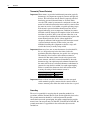
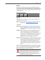
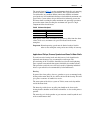
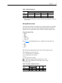
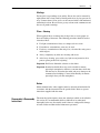
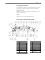
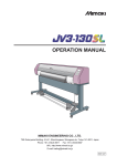
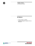
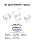
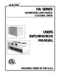
Installation, Operation
and Maintenance Manual
DC Motors
•
Frames DC180ATZ, C180ATZ and
DC210ATZ
2
DC Motors
General Description
The products described in this publication are designed specifically for use
on rectified power. The basic design includes Class F Insulation, 1.0 Service
Factor, 40 degree C (104 degree F) ambient, continuous duty, with
drip-proof guarded and force-ventilated enclosure, with horsepower speed
ratings, overload and voltage in accordance with NEMA Standards. A wide
variety of modifications, enclosures and accessories is available.
!
ATTENTION: Only qualified electrical personnel familiar with
the construction and operation of this equipment and the hazards
involved should install, adjust, operate, and/or service this motor.
Read and understand this manual in its entirety before
proceeding. Failure to observe this precaution could result in
personal injury or loss of life.
Table of Contents
General Description . . . . . . . . . . . . . . . . . . . . . . . . . . . . . . . . . . . . . . 2
Receiving and Handling. . . . . . . . . . . . . . . . . . . . . . . . . . . . . . . . . . . 2
Installation . . . . . . . . . . . . . . . . . . . . . . . . . . . . . . . . . . . . . . . . . . . . . 3
Motor Application Data . . . . . . . . . . . . . . . . . . . . . . . . . . . . . . . . . . . 8
Operation . . . . . . . . . . . . . . . . . . . . . . . . . . . . . . . . . . . . . . . . . . . . . 12
Maintenance. . . . . . . . . . . . . . . . . . . . . . . . . . . . . . . . . . . . . . . . . . . 15
Disassembly & Reassembly Instructions. . . . . . . . . . . . . . . . . . . . . 21
Acceptance
Thoroughly inspect this equipment before accepting shipment from the
transportation company. If any of the goods called for in the bill of lading or
express receipt are damaged or the quantity is short, do not accept them
until the freight or express agent makes an appropriate notation on your
freight bill or express receipt. If any concealed loss or damage is discovered
later, notify your freight or express agent at once and request him to make
an inspection. We are willing to assist you in collecting claims for loss or
damage in shipment; however, this willingness on our part does not remove
the transportation company's responsibility in reimbursing you for
collection of claims or replacement of material. Claims for loss or damage
in shipment must not be deducted from the invoice, nor should payment of
the invoice be withheld awaiting adjustment of such claims, as the carrier
guarantees safe delivery.
If considerable damage has been incurred and the situation is urgent,
contact the nearest Allen-Bradley Sales Office for assistance. Please keep a
written record of all such communications.
DC Motors
3
Handling
!
ATTENTION: Eyebolt(s) or lifting lug(s) are intended for
lifting the motor only with the standard accessories such as
tachometer, brakes, etc., mounted by Allen-Bradley. The lifting
means on the motor must not be used to lift the unit plus
additional equipment. The lifting means on the motor cannot be
used to lift assemblies or equipment mounted on a common base.
Failure to observe this precaution could result in personal injury.
In all cases, care should be taken to assure lifting in the direction intended
in the design of the lifting means. Lift using all lugs provided. Likewise,
precautions should be taken to prevent hazardous overloads due to
deceleration, acceleration or shock forces.
Angle of lift with rope or chain must be greater than 45 degrees from
horizontal.
For unusual conditions, such as side-wall and ceiling mounting of
horizontal motors or installation of vertical motors shipped in a horizontal
position, special precautions must be taken. It is recommended that an
experienced rigger be employed.
Storage
Motors must be stored in a clean, dry area protected from extremes of
temperature, moisture, shock and vibration. Storage temperatures of 10 to
49 degrees C (50 to 120 degrees F) with a maximum relative humidity of
60% must be observed. In addition, motors subjected to extended storage
must be handled and treated per the requirements specified in publication
“Motors-5.0.” This publication is available from your Allen-Bradley Sales
Office or online at: http://www.controlmatched.com.
Installation
DC motors have characteristics which can cause serious or fatal injury
unless they are selected, installed, maintained and operated by qualified
personnel familiar with special requirements of DC machines.
Allen-Bradley DC motors are designed and built in accordance with Safety
Standard for Construction and Guide for Selection, Installation and Use Of
Electric Motors And Generators published by the National Electrical
Manufacturers Association (NEMA), publication MG-2-1983 (ANSI
C51.5). It is recommended that this publication be referred to whenever you
select or install any motor.
The application of motors and other electrical equipment in hazardous
locations is restricted by the National Electric Code. Users must observe
these regulations and consult with local code inspection and enforcement
agencies to insure compliance.
4
DC Motors
Location
Locate the machine where the ambient temperature is not over 40 degrees C
(104 degrees F) and where clean air has free access to ventilating intake and
outlet openings. Except for machines with a suitable protective enclosure,
the location should be clean and dry.
Important: Sufficient clearance must be provided on all inlet and outlet
openings to provide for unrestricted flow of air. Separately
ventilated motors with exhaust to ambient (pipe-in only) must
have at least 152.4 mm (6 in.) of clearance between the opening
and adjacent walls or floor.
Air Supply
Cooling air through a self-ventilated or forced-ventilated motor must be
clean and have relative humidity between 30 and 100% with no free water
in the air. Use of damp, cool outside air with high humidity and free water
may cause the motor to flash over. Use of excessively dry air may cause
excessive brush and commutator wear. Cooling air temperature must not
exceed the maximum ambient temperature indicated on the motor
nameplate (standard 40 degrees C/104 degrees F). Cooling air temperature
must not be lower than 0 degrees C (to provide base speed and regulation
within NEMA limits). Use of outside air below 0 degrees C may cause
excessive brush and commutator wear due to the low humidity. Cooling air
absolute humidity must be at least 2 grains per cu. ft.
Important: Motors located in damp, moist environment must have space
heater or fields energized at 50% voltage to protect against
condensation when motor is not operating.
Separately ventilated motors must have the following volume of air to
adequately cool the motor unless the motor nameplate specifies a different
value.
Frame
DC180ATZ,
C180ATZ and
DC210ATZ
Base Speed
RPM
2500
1750 and lower
Air Volume
CFM
152
105
Static Pressure
Inches of Water
2.0
0.95
Power Supply
Check the motor nameplate to be sure the voltage and type of power rating
is the same as that of the power source.
A code stamped on the nameplate identifies the type of power supply that
must be used to supply armature power to the motor in order to obtain the
rated nameplate output. Since the code letter has been selected in alphabetic
order of increasing magnitude of ripple current, a motor may be operated on
a power supply having a letter designation prior in the alphabet to the letter
stamped on the nameplate, with no loss in nameplate rating.
DC Motors
5
For example, a motor designed for a D type of power supply may be used
on a C power supply having the same voltage rating. The types of power
supplies are defined as follows.
Description
DC generator, battery or twelve pulse/cycle, 6 phase, full control
Six pulse cycle, 3 phase, full control 230 or 460 volt, 60 Hz input to rectifier
Three pulse/cycle, 3 phase, semi-bridge, half control 230 or 460 volt, 60 Hz input to rectifier
Three pulse/cycle, 3 phase, half-wave (single way) 460 volt, 60 Hz input to rectifier
Two pulse/cycle, 1 phase full wave (bridge circuit with 2 controlled rectifiers and
2-uncontrolled rectifiers with free wheeling rectifier) 230 volt, 60 Hz input
Code 1
A
C
D
E
K
1
When the armature power supply cannot be designated by a single letter code (A. K etc.) the power supply shall
be identified by the following code stamped on the motor nameplate: “M/N F-V-H-L.”
where M = Total pulses per cycle
N = Total controlled pulses per cycle
F = Free wheeling (if used)
V = Nominal line-to-line a-c voltage to rectifier
H = Line frequency-Hz
L = Value of series inductance (in millihenries) to be added externally to the motor armature circuit.
Examples:
A. "6/3 F-380-50-12" defines a power supply having 6 total pulses per cycle, 3 controlled pulses per cycle
(S-3), with free wheeling, 380 volts. 50 Hz AC input to bridge, and a 12 millihenry choke to be added
externally to the motor armature circuit.
B. "3/3 480" defines a power supply having three total pulses per cycle, three control pulses per cycle. 480
volts line-to-line input to the rectifier. 60 Hz power supply and no external inductance required in the
armature circuit. Note that since the power source is 60 Hz and no series inductance is required. both
quantities may be omitted from the code. If one of the quantities is indicated, both must be included to
avoid confusion.
Conduit Box
Conduit boxes can be rotated in 90 degree increments for lead outlet at top,
sides or bottom.
Conduit box locations can be changed from F1 to F2 or F2 to F1 by rotating
the commutator end bracket 180 degrees and reconnecting the leads. The
conduit box location cannot be changed on DC180ATZ & DC210ATZ
frames.
Connections
Important: If motor has parallel leads, all lugs with the same marking: For
example, A1, A1, must be connected together.
Figure 1 Basic DC Motor and Generator Connections
Rotation Facing Commutator End
CCW
Type
Motor
Generator
CW
+A1
–S2
A1
–S2
A2
+F1
+A2
+F1
S1
–F2
S1
–F2
A1
–S2
A1
S2
+A2
–F1
+A2
+F1
S1
+F2
–S1
–F2
If machine has no series field, disregard S1 and S2 above. For machines
with special windings, refer to motor or generator and controller diagrams.
6
DC Motors
Thermostat (Thermal Protector)
Important: When motors are provided with thermal protection (typically
thermostats), it is important to properly connect and apply the
devices. This will ensure that the motor is properly protected
from being operated if thermal limits are reached and/or
exceeded. The control system must be configured to reduce the
motor load and/or shut down the motor control system to allow
the motor to cool to a level within acceptable operating ranges.
If the motor is operated with the thermal protective devices
tripped (indicating an over temperature condition), the motor
insulation could be damaged and complete failure of the motor
insulation is possible. In the event of motor failure due to an
over temperature condition, Rockwell Automation requires that
motor thermal protective devices (when supplied) be
adequately monitored and incorporated into the motor control
system to maintain warranty. Failure on the part of the
individual installing this equipment to take these steps will
result in the factory warranty being voided.
Important: Motors may have one or more thermostats (leads marked P1,
P2, etc.) designed to trip before the frame reaches the
maximum allowable temperature for specific class and group.
The normally closed contacts of the thermostat must be
connected in that motor control circuit so that power to the
motor armature and field is removed immediately when the
thermostat trips. An explosion-proof tachometer mounted on
the motor will also have an internal thermostat which must be
connected to stop the drive within 30 seconds upon tripping.
Failure to connect the thermostat leads will void the motor
warranty. the rating of the thermostat contact is:
Maximum Voltage
Rated Current
Maximum Breaking Current
250V, 60 Hz
6.3 amps
20 amps
Important: Motors with an overspeed switch must have the overspeed
switch terminals properly connected in the control circuit to
remove armature power when the switch reaches the set speed.
Grounding
The user is responsible for assuring that the grounding method is in
accordance with the National Electric Code and the applicable local codes.
The ground connection should be a solid and permanent metallic
connection between the ground point, the motor terminal housing and the
motor frame. On two pole units, DC180ATZ, C180ATZ & DC210ATZ, the
ground connection is a tapped hole in the end bracket adjacent to the
conduit box.
DC Motors
7
Mounting
Motors must be mounted on a rigid, solid base or foundation. Poor base
construction may cause resonances in the motor/base assembly which can
result in bearing failure and other motor damage. All hold down bolts must
be the correct grade for the type of mounting and must be torqued to their
recommended value.
Table A Recommended Torque
Hole Diameter Bolt Size and SAE Grade I Dry Components-Not Lubricated
Frame
mm (in.)
Thread
N-m (lb.-ft.)
C180ATZ 11.2 (0.44)
3/8-16
1.81 (16)
Belted Drive
Motor slide bases or rails, when used, must be securely anchored to the
foundation with the proper bolts.
Important: The motor shaft and load shaft must be parallel and the sheaves
aligned. Refer to “Motor Application Data” on page 8.
Coupled Drives
Important: Flexible couplings must be used between the motor shaft and
the load shaft. Motor shaft and load shaft must be aligned to
values recommended for the specific coupling before coupling
is connected.
Important: Motors will operate successfully mounted on the floor, wall or
ceiling, and with the shaft at any angle from horizontal to
vertical. Special mountings, duty or thrust demands may,
however, require a different bearing system. Drive-end bracket
and/or outer caps can be rotated either 90 or 180 degrees to
conveniently locate grease fittings, or air outlet openings.
Handhole covers can be interchanged as necessary.
Important: Vertical mount drip covers are required to provide protection to
vertically mounted Drip-Proof motors. Stock motors and other
motors designed for horizontal mounting can be adapted for
vertical mounting by ordering vertical mount drip covers.
Self-ventilated frames cannot be mounted vertical shaft up and
retain the drip-proof feature due to louvers on the drive end
bracket.
Motor C-Face is intended for mounting auxiliary equipment such as pumps,
gears, etc. When mounted horizontally, these motors should be supported
by the feet and not by the C-Face. Installations requiring a horizontally
mounted motor without feet should use a D-Flange.
!
ATTENTION: Surface temperature of the motor enclosure may
reach temperatures which can cause discomfort or injury to
personnel coming into contact with hot surfaces. The user must
apply appropriate guards and/or shields to protect against
accidental contact with motor surface. Failure to observe this
precaution may result in personal injury.
8
DC Motors
Direction of Rotation
Unless otherwise ordered, brush rigging is assembled for NEMA standard
direction of rotation, counterclockwise for motors and clockwise for
generators facing the commutator end. These motors will operate in either
direction of rotation, without changing the angle of the brush holders for
normal field weakened speed ranges. Extended field weakened speed range
motors should have the direction of rotation specified.
Drive
DC180ATZ, C180ATZ & DC210ATZ frame motors are supplied with a
shaft suitable for a belt or coupled drive.
Proper alignment is a key step for long life of bearings, shafts and belts, and
minimum downtime. Misalignment can cause excessive vibration and
damaging forces on shaft and bearings. For direct coupled drives, flexible
couplings facilitate alignment. For belt drives, the driving and driven
tension must be adjusted as required for proper operation. The belt sheaves
should be placed as close as possible to the motor bracket.
!
ATTENTION: To guard against personal injury and/or machine
damage caused by incorrect motor rotation, verify direction of
motor rotation before coupling motor to load.
!
ATTENTION: Ensure that all guards are properly installed, to
guard against personal injury caused by contact with rotating
parts,
Shipping Blocks
Motors supplied with roller bearings at the drive end are shipped with
wooden blocking to prevent axial movement of the shaft during shipment.
Remove the blocking and bolts securing it and discard. Make sure motor
shafts turn freely. If motor is to be reshipped, blocking of bearing is
required.
Motor Application Data
Maximum Safe Speed
!
ATTENTION: The machinery builder and/or user are
responsible for assuring that all drive train mechanisms, the
driven machine, and process material are capable of safe
operation at the maximum speed at which the machine will
operate. Failure to observe these precautions could result in
personal injury.
DC Motors
9
The speeds given in Table B are the maximum mechanically safe operating
speeds for frames with standard construction. These speeds must not be
exceeded under any condition. Motor control must hold the maximum
speed under any load condition including no-load within the maximum safe
speed. Drive systems whose design characteristics inherently prevent the
DC motor from exceeding the motor maximum safe operating speed must
prevent the motor from exceeding the maximum safe speed if a single
component failure should occur.
Table B Maximum Safe Speed
Frame Diameter
DC180ATZ
C180ATZ
DC210ATZ
Maximum Safe Speed
4500 RPM
5000 RPM
4500 RPM
With special construction, maximum safe speed may differ from the above
values. In all cases, maximum safe speed is indicated on the motor
nameplate.
Important: Normal operating speeds must be limited to those listed in
order to meet nameplate rating and assure validity of warranty.
Application of Pulleys, Sheaves, Sprockets and Gears On Motor Shafts
To avoid excessive bearing loads and shaft stresses, belts should not be
tightened more than necessary to transmit the rated torque. The
pre-tensioning of the V-belt drive should be based on the total tightening
force required to transmit the horsepower divided by the number of belts.
This procedure avoids the excessive load caused by tightening individual
belts to a prescribed level recommended by belt manufacturers.
Mounting
In general, the closer pulleys, sheaves, sprockets or gears are mounted to the
bearing on the motor shaft, the less will be the load on the bearing. This will
give greater assurance of trouble-free service.
The center point of the belt, or system of V-belts, must not be beyond the
end of the motor shaft.
The inner edge of the sheave or pulley rim should not be closer to the
bearing than the shoulder on the shaft but should be as close to this point as
possible.
The outer edge of a chain sprocket or gear must not extend beyond the end
of the standard motor shaft.
10
DC Motors
Shaft Extension and Method Of Drive
V-belts should be within the limits of NEMA Standard MG1-14.67.a.
Frames DC180ATZ, C180ATZ, DC210ATZ are supplied with the same size
shaft for either coupled or belted drives.
Table C Multipliers for Drives other than V-belt
Drive
Flat Belt (See Note 1)
Timing Belt (See Note 2)
Chain Sprocket
Spur Gear
Helical Gear
Multiplier
1.33
0.9
0.7
0.75
0.85
1
The above multiplier is intended for use with conventional single-ply flat, belts. When other than single-ply flat belts
are used, the use of a larger multiplier is recommended.
2
It is often necessary to install belts with a snug fit. However, tension should be no more than necessary to avoid
belt slap or tooth jumping.
Shaft Loads – Axial and Radial
DC motors are suitable for limited shaft load as shown in Tables D and E.
Recommended maximum thrust loads depend on the mounting position,
either horizontal or vertical. For load recommendations in excess of those
shown, contact your local Sales Office.
!
ATTENTION: The use of these radial load capacities requires
the accurate calculation of the radial load for the application.
Radial loads for gears, sprockets, and flywheel are usually
accurately determined but the radial loads due to V-belt drives are
subject to miscalculations because they do not include all of the
pre-tension load (belt tightening). The calculations of the radial
load for a V-belt drive must include the pre-tension for
transmitting the horsepower, pre-tension for centrifugal force on
the belts, pre-tension for high start torques, rapid acceleration or
deceleration, pre-tension for drives with short arc-of-contact
between the V-belt and sheave, and low coefficient of friction
between belt and sheave caused by moisture, oil or dust. Failure
to observe these precautions could result in damage to or
destruction of the equipment.
Table D Axial Thrust Capacity 1
Horizontal Mounting
Frame
Units 2500 RPM 1750 1150
DC180ATZ & lbs.
176
207
251
DC210ATZ
kg
80
94
114
C180ATZ
lbs.
295
345
417
kg
134
156
189
1
850
286
130
477
216
Vertical Mounting
2500
1750
190 ± 45 217 ± 45
86 ± 20
99 ± 20
370 ± 45 357 ± 45
139 ± 20 162 ± 20
1150
265 ±
120 ±
430 ±
195 ±
45
20
45
20
850 RPM
295 ± 45
134 ± 20
492 ± 50
223 ± 20
Thrust capacity for vertical mounting includes a constant whose value is plus or minus depending on the
direction of the thrust load. The constant is plus for thrust loads acting upward against the force of gravity and
minus for loads acting downward with gravity.
DC Motors
11
Table E Radial Load Capacity 1
Capacity at End of Shaft in kg (lbs.)
Frame
2500 RPM
1750 RPM
1150 RPM
DC210ATZ & 140.6 (310)
156.5 (345)
179.2 (395)
DC180ATZ
C180ATZ
226.8 (500)
256.3 (565)
283.5 (625)
1
850 RPM
200.0 (440)
283.5 (625)
Data for motors with roller bearings at the drive end (back end). Motors with ball bearings at the drive end are
for coupled duty only.
Deriving Motor Constants
Various motor constants are required to set control functions for stabilized
operation of motor and controls. The following information will make it
possible to derive approximate motor constants from the nameplate data.
Required Nameplate Data
• Frame
• HP
• RPM
• Volts (Va)
• Amps (Ia)
From Table F, the following factors are available, based on frame size.
•
•
•
•
Ra´
La´
WK2
τe´
This will provide approximate results with a ±25% margin of error.
The following data can be derived:
La = La´ x (Va/rpm)2 Arm. Circ. Ind. (millihenries)
Ra = Ra´ x (Va/rpm)2 Arm. Circ. Resistance
τe = τe´
τe´ = La/Ra x 103 Elec.Time Constant
J (SEC) = WK2 x (rpm)2/1.62 x (10)6 x hp where WK2 is in terms of lb-ft2
J (SEC) = WK2 x (rpm)2/0.0922 x (10)6 x kw where WK2 is in terms of kg-m2
R = Ia x Ra/(Va – IaRa)
Table F Resistance & Inductance Factors
Frame
C1811ATZ
C1812ATZ
WK2
lb.-ft.2
0.683
0.787
kg.-m.2
0.029
0.033
Ra
56.6
40.5
La
616
500
τe
0.011
0.012
12
DC Motors
Operation
Balance
Motors are dynamically balanced to commercial limits unless ordered
differently. Balance is done with a full length 1/2 height shaft key. A full
shaft key is shipped with the motor. Sheave or coupling should be balanced
with a 1/2 height shaft key.
Table G Standard Dynamic Balance Limits
Highest Rated Speed
(RPM)
3,000 - 4,000
1,500 - 2,999
1,000 - 1,499
Up to 999
Maximum Amplitude
(Inches)
0.0010
0.0015
0.0020
0.0025
Series Wound Motors
Important: Series wound motors must be solidly connected to the driven
machine and never operated without load to avoid possible
destructive high speeds.
Motor Start-up
!
ATTENTION: To guard against personal injury and/or machine
damage, observe the following precautions before initial start-up:
• Remove all unused shaft keys and loose rotating parts to
prevent them from flying off. Replace covers and protective
devices.
• Verify that all separately excited fields are excited at their rated
voltage and that relative polarities of all fields are correct. See
“Checking Relative Polarity of DC Motor Fields” on page 14.
• When the motor is supplied as part of drive system, refer to the
Drive User Manual for operating instructions. Tachometer
feedback must be properly connected for closed loop
operation. Reverse polarities or broken connections can cause
dangerous overspeeds.
Maximum safe mechanical operating speeds are shown in
Table B on page 9. Motor control circuitry must prevent motor
speeds from exceeding the stated values.
DC Motors
13
In addition to observing the above precaution, all precautions (Attentions)
mentioned in this document should be observed. The following items must
be checked before starting and during operation.
• The armature should rotate freely and be clear of any obstructions.
• The brushes should move easily in their holders and should make
proper contact on the commutator.
• The interior of the motor should be clean and dry.
• Connections must be tight.
• The driven machine should be unloaded, if possible.
When starting, small sparks may appear on the commutator due to particles
of dirt. Other than this. there should be little, if any, sparking at the brushes.
Important: Machines designed for cooling by a separate source of forced
ventilation must not be operated without the air supply. Be sure
blower is running in proper direction.
While operating the motor, observe the performance. It should run smoothly
with little noise. The bearings should not overheat and should reach a
leveling off temperature. Any undue noise, overheating, sparking or erratic
performance should be investigated and necessary corrective action taken
immediately to prevent serious damage. Before attempting any repairs,
please contact your Allen-Bradley Sales Office.
All motors are lubricated before shipment and will operate for a long period
before regreasing is required. The period will vary depending on
environmental and service conditions. Refer to “Maintenance” on page 15.
!
ATTENTION: Surface temperature of the motor enclosure may
reach temperatures which can cause discomfort or injury to
personnel coming into contact with hot surfaces. The user must
apply appropriate guards and/or shields to protect against
accidental contact. Failure to observe this precaution may result
in personal injury.
14
DC Motors
DC Motor Field Heating
!
ATTENTION: To guard against motor damage caused by
inadequate ventilation, assure that motors designed for forced
ventilation as standard have cooling air when fields are excited at
rated voltage. Installations having the air supply interrupted when
the motor is not operating must have field disconnected or field
voltage reduced to 67%, rated by means of field economizing
resistor and relay. The motor insulation life can be significantly
reduced if the above precaution is not followed.
Standard continuous duty DPG, TEFC and TENV stabilized shunt wound
DC motors have continuous duty fields capable of continuous excitation at
standstill (armature circuit not energized) under normal industrial
conditions.
Important: Motors designed for forced ventilation or with a dual-cooled
heat exchanger as standard must have cooling air when fields
are excited at rated voltage. Installations having the air supply
interrupted when the motor is not operating must have field
disconnected or field voltage reduced to 50% rated by means of
field economizing resistor and relay.
Standard continuous duty self-ventilated motors are suitable for rated load
at rated speed operation at field voltages up to 110% of rated value.
However, insulation life will be reduced if operated below 60% of base
speed for prolonged periods.
Checking Relative Polarity of DC Motor Fields
Motor speed is unstable if speed increases due to an increase in load
current. As a result of instability, motor speed may hunt or overspeed. These
are unsatisfactory, possibly dangerous, drive conditions.
One of the possible causes of unstable performance of shunt wound DC
motors is incorrect series field polarity relative to the shunt field due to
improper connection. Relative polarity of the shunt and series fields can be
checked as follows:
1. Connect a low scale (3 volt) DC voltmeter across the shunt field
terminals (F1, F2) with F1 connected to the positive (+) terminal of the
meter. At least one of the shunt field leads must be disconnected from
the controller.
2. Use two flashlight batteries as a source of low voltage (3 volts). Hold or
connect the negative, to contact the S-2 series field terminal. Hold one
end of a wire conductor to the positive (+) center terminal so that the
other end of the wire can be used to make and break contact with the S-I
series field terminal.
3. Watch the deflection of the voltmeter needle when contact is made with
S-I and when contact is broken.
DC Motors
15
4. When contact is made, the needle will first deflect in either the up scale
or down scale direction and then return to zero. Deflection will be in the
opposite direction when contact is broken.
5. Relative polarities of the shunt and series fields are correct
(ampere-turns are cumulative) if the voltmeter needle deflects up scale
when contact is made and down scale when contact is broken.
6. Relative polarities of the shunt and series fields are incorrect
(ampere-turns are differential) if the voltmeter needle deflects down
scale when contact is made and up scale when contact is broken. The
motor connections must be changed so that relative polarity is correct.
Relative polarity can be incorrect because of an error in the connections to
the control or because the series fields leads are improperly marked. In any
case, the motor connections must be changed so that relative polarity is
correct.
If only one series field terminal is available at the controller, use it and the
available armature terminal for the test. For example, use S-2 and A-l, if S-1
and A-2 arc connected together at the motor and not brought to the
controller.
Maintenance
!
ATTENTION: Internal parts of this motor may be at line
potential even when it is not rotating. Before performing any
maintenance which could result in contacting any internal part, be
sure to disconnect all power from the motor. Failure to observe
this precaution could result in severe personal injury or death.
Inspections
Regular inspection at intervals dependent upon service conditions is the best
insurance against costly maintenance and breakdown. Experience is the best
guide. Record inspection results and maintenance action required or
performed.
Cleanliness
Keep the interior parts of machines clean and dry. Remove dust, dirt,
corrosion, grease, oil and moisture. If used, ventilating air filters must be
kept clean or replaced to assure full volume of cooling air.
Lubrication - Frames DC180ATZ & DC210ATZ
DC180ATZ frame has oversize grease reservoirs to provide lifetime
operation in normal industrial applications. Where severe duty conditions
require regreasing, the following procedures should be followed:
16
DC Motors
Drive End Bearing
Bearing fits in machined cavity in bracket with inner cap. To regrease
bearing, remove bracket (four nuts hold bracket to frame) and inner cap
(two bolts). Clean old grease from bearing and cavity and repack with
Chevron SRI-2 or equivalent grease.
Commutator End Bearing
Bearing has single shield and single seal with seal on side facing
commutator. To regrease bearing, snap out brushes and remove bracket
(four nuts hold bracket to frame). Clean old grease from around bearing and
cavity and repack around bearing and Chevron SRI-2 or equivalent grease.
Amount of grease to be added to motors is shown in Table H. See Table J
for relubrication interval. Use Chevron SRI-2 or equivalent grease unless
motor nameplate specifies special grease.
Recommended Lubricant
For motors operating in ambient temperatures shown below, use the
following lubricants or their equivalent:
Ball Bearing Motors
Operating Temperature:
–25 to 50 degrees C (–15 to 120 degrees F)
Minimum Starting Temperature
–60 degrees C (–76 degrees F)
Chevron Oil – SRI No. 2
Exxon – Unirex N2
Shell Oil Co. – Dolium R
Texaco, Inc. – Premium RB
Shell Oil Co. – Aeroshell 7
Table H Coupled/Belted or Tandem Duty Grease Amounts
Frame
C180ATZ
Volume
Weight
Cubic Inches Cubic Centimeters Ounces
1.0
16
0.5
Grams
14
Using the table below, determine service condition on the basis of the most
severe operating parameter (i.e. temperature, bearing load, atmosphere, or
operating hours per day).
Table I Service Condition
Service
Condition Ambient Temperature
Standard –18 to 40 degrees C
(0 to 104 degrees F)
Severe
–30 to 50 degrees C
(–22 to 122 degrees F) 1
Extreme 2 –54 to 65 degrees C
(–65 to 149 degrees F) 1
Operating
Hours/Day
8
Bearing Load
Steady
Atmosphere
Clean
Medium Shock, Vibration
(less than 0.2 in/sec.)
Heavy Shock, Vibration
(more than 0.44 in/sec)
Medium Dirt,
8 to 24
Abrasives, Corrosion
Heavy Dirt,
8 to 24
Abrasives, Corrosion
1
Motors must be specially designed for operation in ambient outside the range of –30 to 40 degrees C
(–22 to 104 degrees F). Special grease is required.
2
“Extreme” service conditions are rare in actual practice. Corresponding lubrication cycles should therefore be
applied with caution. It is also advisable to check with Allen-Bradley for related special instructions.
DC Motors
17
Table J Relubrication Periods – Frames C180ATZ
Maximum Normal
Operating Speed (RPM) 1
3450 and higher
2400 - 3449
1700 - 2399
800 - 1699
500 - 799
499 and lower
1
2
Frame
C180ATZ
C180ATZ
C180ATZ
C180ATZ
C180ATZ
C180ATZ
Relubrication Interval (Months) 2
Standard Severe
Extreme
Service
Service
Service
9
4
1
24
9
3
36
12
3
36
24
8
48
36
12
48
36
12
Maximum speed occupying more than 30% of operating time.
For Tandem drives increase frequency of lubrication by multiplying values by 0.8.
Lubrication – Frames C180ATZ
These motors are designed to route new grease directly into the bearing.
The relubrication periods shown in Table J are offered as a guide for varying
service conditions, speeds, bearing types and operating hours.
Important: Certain special motors may have a lubrication instruction plate
permanently attached. These specific lubricating instruction
must be followed.
Lubrication Procedure
!
ATTENTION: To guard against personal injury or death from
rotating parts or electrical shock, relubrication should only be
performed while the motor is stationary and disconnected from
the power source.
1. Relubrication with the shaft stationary and a warm motor is
recommended.
2. Locate the grease inlet at the top of the bearing hub, clean the area and
replace the 1/8 inch pipe plug with a grease fitting (if the motor is not
equipped with a grease fitting).
3. When provided, remove grease drain plug located opposite the grease
inlet. The following motors do not have a grease drain plug, but have a
grease relief around the grease inlet pipe:
– Frames C180ATZ on commutator end (opposite drive end).
– All C-Face and D-Flange frames on drive end.
4. Using a manual grease gun, pump in the recommended grease in the
amount shown in Table H. This amount of grease will provide an ample
supply of lubricant between lubrication periods as determined from
Table J for the service condition listed in Table I. An excessive amount
of grease will damage the motor.
Use Chevron SRI-2 grease or equivalent unless motor nameplate
specifies special grease. Use only clean, fresh grease from clean
containers and handle carefully to keep it clean.
18
DC Motors
In general, mixing of greases is not recommended. If an incompatible
grease is used, the lube system must be repacked completely with the
new grease.
5. Wipe away any excess grease at the grease drain or relief and replace
drain plugs.
Repacking Bearings or Greasing New Bearings
When existing bearings have been completely cleaned of old grease or
when bearings are replaced, use this procedure for packing the bearing.
1. Apply one bead of grease all around inboard side of bearing between
bearing and inner cap, making sure that grease adheres to balls or rollers.
2. Apply one bead of grease all around outboard side of bearing, making
sure grease adheres to balls or rollers.
3. Completely fill grease inlet and outlet passage holes with grease.
4. Fill outboard bearing cavity 60% to 90% full of grease.
5. If possible, rotate shaft of assembled machine at least three revolutions
by hand to distribute grease within bearings before starting motor.
Bearings
These motors are designed to provide a mounting for anti-friction bearings
to give:
• Maximum protection to windings and interior of machine by preventing
grease leakage from bearing housing.
• Maximum protection to bearings against excess lubricant, insufficient
lubricant, dirt and moisture.
Various types of anti-friction bearings are used in the wide range of frames
as needed to meet specific load, speed and service requirements.
Most commonly used bearings are:
• Single row, open ball bearings for coupled and belted duty for frames
C180ATZ. Frames DC180ATZ and DC210ATZ have a single-shielded
bearing on the commutator end.
Frequent bearing checks are recommended. If temperatures become
excessive, investigate immediately for the cause. Total bearing temperatures
should not exceed 90 degrees C (194 degrees F). Causes for high bearing
temperature are:
•
•
•
•
•
•
•
Contaminated grease.
Insufficient grease or excessive amount.
Incorrect grease.
Excessive load or thrust due to misalignment or motor overload.
Loose bearings.
Bearing failure.
Excessive ambient temperature.
DC Motors
19
Replacement bearings should be ordered from Allen-Bradley in order to
obtain the same carefully selected bearing as the original. Bearings should
never be exposed by disassembly of the motor unless absolutely necessary
for inspection or replacement of the bearing or maintenance in other parts of
the machine. Protect good bearings from dirt and contamination at all times.
Most bearing failures are caused by dirt.
The open ball bearings for motor frames C180ATZ are the same regardless
of whether application is coupled or belted.
Brushes
Brush pressure is correctly established at the factory and maintained at the
correct value throughout the life of the brush by means of a constant
pressure design. Brushes and brush-holders should be clean so that the
brushes are free to move in the holders. Replace brushes with new brushes
of the same grade before wear permits the rivet or tamped pigtail to score
the commutator. It is best to change out complete set.
Fit the face of new brushes to the contour of the commutator with sandpaper
only, no emery abrasive. Keep brush lead (pigtail) connections tight.
Replacement brushes should have sleeved pigtails.
!
ATTENTION: To guard against personal injury or death, ensure
that all power to the motor has been removed and the motor shaft
is stationary. Brushes must not be touched or replaced while
motor is energized or rotating.
Commutator
A commutator in good condition is clean and smooth with a medium polish
and a light brown color. Keep clean by occasionally wiping with a canvas
pad. Use no lubricant or emery abrasive. If a commutator becomes rough, it
needs to be resurfaced. Roughness can be easily detected with the machine
running by resting a pencil-like rod of insulating material (dry wood) on
one of the brushes. In mild cases, a commutator dressing stone can be used.
Very rough or out of round commutators require turning in a lathe. In every
case, maintain concentricity and remove the minimum material required for
proper cleanup. Undercut the mica approximately l/16” and polish. Adjust
brush holders for approximately 1/8” clearance to commutator.
The finished diameter and the minimum diameter of the commutator for the
various frames sizes are as follows:
New Diameter
Frame
Inches
DC180ATZ & 3.01
DC210ATZ
C180ATZ
4.12
Millimeters
76.5
Minimum Diameter
Inches
Millimeters
2.62
66.5
104.8
3.66
93.0
The commutator should be replaced if the final diameter would have to be
turned down to a value less than minimum limits.
20
DC Motors
Commutation
Intermittent sparking due to overloads or slight visible sparking does not
necessarily indicate poor commutation. Poor commutation exists when
there is excessive sparking requiring abnormal maintenance. Every case of
excessive sparking should be investigated to determine the cause and
correct it. The chart in Table K may help in analyzing commutation
problems. DC motors and generators are brushed for full load current. If
unit or units are consistently operated at less than 1/2” rated load a
condition known as threading will result.
Table K Commutation Problem Quick Check
Symptom
1. Excessive sparking at motor
or generator commutator.
Identified By
Sparking
Possible Cause
1. Dirty or corroded commutator due to dirt,
ambient contaminants, oil or oil mist, etc.
2. Brushes incorrectly seated.
3. High or feather-edged mica.
4. Faulty machine adjustment.
5. Interpoles failed or improperly adjusted.
6. Loss of brush spring tension.
7. Brushes sticking in brush holder.
8. Unit overload.
9. Defective commutator or armature.
10. Unequal spacing of holders around commutator.
2. High commutator bars
Generally associated with sparking and noisy operation of 1. Loose commutator.
produce a rough commutator. the brushes on the commutator.
3. Low commutator bars
Generally associated with sparking and noisy operation of 1. Loose commutator.
produce rough commutator. the brushes on the commutator.
2. High mica.
3. Open or high resistance connection at
commutator.
4. Streaking or threading of
Rough commutator with associated sparking. Fine lines in 1. Low average current density in brushes due to
commutator surface.
brush track.
light machine loading.
2. Contaminated atmosphere.
3. Oil on commutator or oil mist in air.
4. Humidity too low.
5. Lack of film forming properties in brush.
6. Brush too abrasive.
5. Bar etching or burning.
Rough commutator with associated sparking and eventual 1. High mica.
flashover.
2. Operation of machine with brushes off neutral.
3. Commutator dirty.
4. Incorrect spring tension.
5. Machine overload or rapid load change such as
plugging.
1. Shorted commutator bars or coils.
6. Bar marking at pole-pitching 1. Two bars marking 180 degrees C (356 degrees F)
2. Open armature or field circuit.
spacing.
apart on 4-pole machine at start.
2. Three bars marking 120 degrees C (248 degrees F) 3. Unequal air gap.
4. Cyclic disturbance either electrical or
apart on 6-pole machine at start.
mechanical.
3. As pitch bar marking progresses, it will eventually
show at all bars on the machine.
4. Associated sparking and eventual flashover.
7. Bar marking at slot-pitch
Sparking and marking of one or more bars at equal
1. Unequal compensation of armature coils. The
spacing.
spacing around commutator according to bar-per-slot ratio
energy unbalance is reflected into the last coil in
with eventual flashover.
the slot to undergo commutation, and will result
in a spark at the brush.
8. Rapid commutator or brush Bright commutator surface.
1. Abrasive material under brush.
wear.
2. Too abrasive a brush.
3. Low average brush current density due to light
machine loading.
4. Contaminated atmosphere.
5. Humidity too low.
6. Incorrect brush tension.
DC Motors
21
Windings
For long life, keep windings clean and dry. Dirt or dust can be removed by
wiping them with a clean cloth, by blowing with clean, dry, low pressure air
or by vacuum cleaner. Oil or grease can be removed with a cloth moistened
with mineral solvent. Be sure not to get any solvent on the commutator and
observe all product warnings.
Filters – Cleaning
When supplied, filters on motors must be kept clean to assure proper air
flow and cooling of the motor. The following procedure should be used to
clean these filters:
1. For light accumulations of dust, use compressed air to clean.
2. For moderate accumulations, water may be used.
3. For heavy accumulations of dirt and grease, clean the filter using water
and detergent.
4. Always completely dry filter after cleaning with water.
5. After heavy cleaning, spray with a very light coat of protective oil to
protect against possible loss of plating.
Important: Do Not use flammable solvents to clean filters.
Important: Standard washable filters may not be suitable for motors
operating in atmospheres with heavy concentrations of oil mist.
Oil mist may be drawn into the motor and cause damage to the
commutator and windings. Contact Allen-Bradley for motors
operating in heavy oil mist atmospheres.
Brakes
Motor mounted brake, when supplied, must be adjusted and maintained in
accordance with the instructions for the specific brake. Refer to separate
instructions supplied with the motor
Disassembly & Reassembly The motor design incorporates many new techniques which are described in
this section. It is recommended that these differences be understood
Instructions
thoroughly before any disassembly work is done to avoid possible damage
or harm to either machine and/or maintenance personnel.
22
DC Motors
Air Gap And Shimming
(Frame C180ATZ)
Main Pole
Steel or brass shims, when used, are placed between pole and frame. If for
any reason the shims are removed they must be replaced under the same
poles. Main pole bolts are steel SAE Grade 5 (120,000 psi).
Axial Float
Frames C180ATZ have wavy spring washers between B.E. bracket and
bearing. Axial float should be within the limits listed on the chart below.
Axial Float
Frame
All
Maximum
1.22 mm (0.048 in.)
Minimum
0.20 mm (0.08 in.)
Anti-friction Bearing Assemblies
The bearings are positioned and secured by various means depending on
size and application requirements. Open type ball bearings are used for
direct coupled and belt drive applications. Below are standard construction
details for the various frames.
DC180ATZ & DC210ATAZ
Drive end bearing fits in a machined cavity in the bracket with inner cap.
Commutator end bearing has single seal on side facing commutator.
C180ATZ
Bearings fit in a machined cavity in the end brackets. Inner caps are used.
Bearing Replacement
Remove bearing by means of bearing puller. Clean bearing housing and
bearing seat prior to assembly of bearing. Place new bearing in a bake oven
for one hour at 121 degrees C (250 degrees F). Place bearing onto shaft and
push home to bearing shoulder. Hold it in place for a minimum of 30
seconds.
After bearing has cooled down for about 1 minute, add 1/2 cu. in. of fresh
grease into back of bearing. When the motor has been assembled, grease per
instructions found on page 15.
DC Motors
23
Brush Rigging and Brush Holders
The brush holders in all motors are often constant pressure design and do
not require nor are capable of adjustment over the life of the brushes.
DC180ATZ & DC210ATZ
Conduit box is attached to the commutator end top hand hole cover and
cannot be located on the side.
C180ATZ
Conduit box is located on the commutator end bracket.
Parts Identification C180AT, DC180ATZ & DC210ATZ
Number
1
2
3
4
5
6
7
8
9
10
Description
Grease Plug (C180 only)
Grease Plug (C180 only)
Ball Bearing
Ball Bearing
Rocker
Bracket
Bracket
Brush
Brush Holder
Commutator
11
Field Coil
FE
BE
FE
BE
FE
BE
Number
12
13
14
15
16
17
18
19
20
21
Description
Inner Coil
Armature Core
Frame
Armature Coil
Inner Fan
Key
Shaft
Conduit Box
Bearing Cap
Bearing Cap (C180 only)
(Cap not shown)
BE
FE
Online Documentation
The latest motor information can be obtained from the Allen-Bradley
Drives & Motors home page on the World Wide Web at:
http://www.controlmatched.com
Publication 1325L-UM001B-EN-P – August, 2001
Supersedes 1325L-UM001A-EN-P dated May, 2001
Copyright © 2001 Rockwell Automation. All rights reserved. Printed in USA.