1
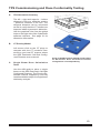
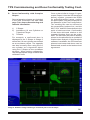
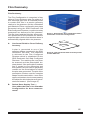
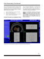
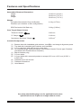
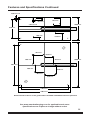
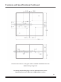
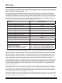
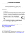
WWW.
.COM
REF 91250
STANDARD IMAGING, INC.
3120 Deming Way
Middleton, WI 53562-1461
TEL 800.261.4446
TEL 608.831.0025
FAX 608.831.2202
Oct / 2014 ©2014 Standard Imaging, Inc.
DOC #80527-04
General Precautions
WARNING:
Follow manufacturer’s recommended safety procedures
for radioactive sources.
Warnings and Cautions alert users to
dangerous conditions that can occur if
instructions in the manual are not obeyed.
Warnings are conditions that can cause
injury to the operator, while Cautions can
cause damage to the equipment.
CAUTION:
Do not drop or mishandle the
slabs.
CAUTION:
Refer all servicing to qualified
individuals.
CAUTION:
Proper use of this device depends on careful reading of
all instructions and labels.
2
Table of Contents
PAGE
2 General Precautions
3 Overview
6 General Operation
7 Optional SRS Dosimetric QA Slab
8 CyberKnife® Sample Dosimetry Tests
10 Ion Chamber Configuration
13 TPS Commissioning and Dose
Conformality Testing
15 Film Dosimetry
17 SDVP Heterogeneity Insert
18 Maintenance
18 Parts and Accessories
19 Features and Specifications
3120 DEMING WAY
MIDDLETON, WI 53562-1461 USA
WWW.STANDARDIMAGING.COM
Overview
The Stereotactic Dose Verification Phantom can be used for a wide variety of tests
including routine absolute dosimetry output
checks and treatment planning system(TPS)
commissioning and quality assurance(QA)
tests as recommended by TG 53 and IEC
430 Treatment Planning System Commissioning and QA Standards. Patient specific
dosimetry tests can be performed easily
as well. The fixed portion of the phantom
consists of the top and bottom 4 cm slabs
that contain:
•Gold fiducials for positioning setup accuracy,
•Lead BBs diameter 1 mm at known precision manufactured locations on three corners so that superior – inferior, left – right,
anterior – posterior and diagonal geometric
distances can be confirmed in the imported
patient CT studies thus demonstrating that
no distortion is evident.
The bottom slab has two rigid alignment
posts that ensure all phantom configurations
are precisely and reproducibly aligned, for
every insert used with the phantom. Additional large Blue Water blocks are available
so that the 20 x 20 x 10 cm dimension can
be increased to a 30 x 20 x 20 cm.
2 BBs shown overlapped
lead BB
gold fiducials
gold fiducials
lead BB
Front View
lead BB
2 BBs shown overlapped
gold fiducials
lead BB
Top View (larger marks indicate marker
located in top slab)
3
Overview Continued
Center Slab Configuration Details
Two standard configurations of the 2.0
cm thick center slab accommodate an ion
chamber or film. The Heterogeneity Insert
and SRS Dosimetric QA Slab provide additional options.
Ion Chamber Configuration
The Ion Chamber Configuration consists of a
2 cm slab with interchangable 5/8” diameter
plugs drilled to accept an ion chamber of
choice. The centroid of the chamber’s collecting volume coincides with the center of the
slab and can be identified radiographically
with the center of mass of the embedded gold
markers. Additional plugs for other thimble
ion chambers or diodes are available.
Ion Chamber Configuration
for dose measurements
Film Configuration
The Film Configuration consists of two 5 mm
slabs and five 2 mm slabs. The 2 mm slabs
are machined to precisely position film cut to
dimensions of 63.5 mm x 63.5 mm (2.500”
x 2.500”, ± 0.007"); this stack of five 2 mm
slabs is positioned between the 5 mm slabs.
The recessed pocket in each slab accomodates the thickness of the GAF film.
Film Configuration
for patient specific or treatment
plan dose verification
NOTE: It is advised to mark each individual
film for identification and orientation purposes to avoid mistakes during assembly
and disassembly of the phantom.
4
Overview Continued
SDVP Heterogeneity Insert Configuration
(Optional, REF 72313)
The SDVP Heterogeneity Insert consists of
two 5 cm slabs of lung-equivalent material,
and one 2 cm chamber slab. The chamber
slab is placed between the two thicker lung
slabs, and the entire lung-equivalent assembly is then placed between two standard
Blue Water SDVP end slabs. The chamber
plug with gold markers for the SDVP Heterogeneity Insert is made of Blue Water, and is
designed to simulate a small tumor within the
lung equivalent material. The SDVP Heterogeneity Insert is used with an ion chamber
or other small detector to perform small field
tests in a highly heterogeneous environment.
Heterogeneity Insert Configuration
for small field tests in a highly heterogenous
environment
SRS Dosimetric QA Slab Configuration
(Optional, REF 70650)
The SRS Dosimetric QA Slab is available as
an accessory which provides a third option
for the center slab. It contains targets which
test treatment planning and CT number
accuracy. Used in conjunction with the ion
chamber and film configurations, the SRS
Dosimetric QA Slab tests the accuracy of the
TPS planned dose delivery. More information
is available in the Optional SRS Dosimetric
QA Slab section on page 6 of this manual.
Optional SRS Dosimetric QA Slab
(REF 70650)
5
General Operation
The Stereotactic Dose Verification Phantom is easily set up for single beam dose output tests,
as well as treatment plan delivery dose verification tests for a number of tracking methods.
1. G e n e r a l P h a n t o m S e t u p a n d
Assembly. The alignment posts of
the phantom do not allow accidental
incorrect assembly of the phantom
slabs. Rotated or inverted slabs are
visually apparent. This is critical for the
repeatability of assembly, as well as
ensuring the embedded gold markers
are in their correct orientation at all
times. An alignment mark ( similar to a
dimple) is located in the corner of each
slab for use as a quick visual guide.
Orient each slab with this mark facing
upward and directly over the mark on
the previous slab.
Once assembled, thread the desired
screws into the alignment posts until
firm – do not over tighten!
2. Scanning the phantom with CT
imager. Arrange the assembled
Stereotactic Dose Verification Phantom
on the CT table and align appropriately.
Use the same scan parameters as for
a typical patient to scan the phantom.
3. Position the phantom on the treatment
couch. Position the Stereotactic Dose
Verification Phantom on the treatment
table and properly align to the alignment
lasers. Image the phantom to confirm
that the phantom position matches the
planning CT position.
4. Treat the phantom. Treat the phantom
as required to test the dosimetry and
imaging functions of the specific TPS
to be evaluated.
nylon screws
SRS Dosimetric QA Slab
Configuration (Optional)
SDVP Heterogeneity Insert
Configuration
thumb screws
Film
Configuration
Ion Chamber
Configuration
Four methods of Stereotactic Dose Verification Phantom assembly
6
SRS Dosimetric QA Slab
The SRS (Stereotactic Radiosurgery) Dosimetric QA Slab consists of three main components:
air pocket, core target shapes, and CT density plugs. See material specifications section on
page 18.
Air Pocket
The air pocket is used to test the
dose calculation accuracy.
Core Target Shapes
The core target shapes, with their
corresponding avoidance structures,
are used to test complex dose delivery
plans and a relative dose shape
against objects of known dimension.
The 6 x 6 cm core insert containing
the shapes can be removed to be
re-orientated in the slab for additional
positioning. (See dimensions below.)
Thickness of all shapes is 20.0 mm.
CT Density Plugs (3 total)
From left to right: Adipose, Cortical Bone,
and Trabecular Bone. Thickness of all
plugs is 20.0 mm.
Alignment Mark
SRS Dosimetric QA Slab
R 3.18 mm
7.11 mm
2.11 mm
Ø 6.0 mm
Ø 20.0 mm
31.75 mm
Ø 6.0 mm
Ø 10.0 mm
Ø 20.0 mm
Core Target Shape Dimensions (not drawn to scale)
7
CyberKnife® Sample Dosimetry Tests
The following section describes the steps
required to perform:
•
Absolute Dose Traceability where a
simple multibeam isocentric forward
plan is generated to the Stereotactic
Dose Verification Phantom Ion Chamber Configuration (see page 4).
•
Collimator Output Dose Delivery
Verification is done using the smallest
micro chamber in the ion chamber
configuration. For example, using the
5 mm collimator with the output factor
of 0.7, an inversely planned conformal
plan is generated to an Exradin Micro
Chamber with an expected dose of 10
Gy. The measured nC delivered to the
phantom versus expected nC from the
treatment plan should be within 5%.
•
Treatment Planning and Dose Delivery Conformality and Dosimetric
Accuracy Highly conformal plans are
generated using the optional SRS Dosimetric QA Slab Configuration (see page
4) which contains the complex shape
used for planning.
After import of the plan into the CyberKnife delivery system, the plan is
delivered to the Film Configuration
(see page 4). A fiducial plan guarantees
sub-millimeter positioning accuracy of
the film since the fiducials are embedded in the top and bottom portion of the
phantom.
The resulting film can be placed directly
on the conformality shape of the SRS
Dosimetric QA Slab for a qualitative
check of the actual delivered dose
shape relative to the actual complex
shape that was planned. If film dosimetry such as a calibrated RIT system is
available, prescribed versus measured
actual dose can also be verified from
the film, as well as the Distance to
Agreement(DTA) values. If desired,
the highly conformal plan can also be
treated to the Ion Chamber Configura-
CyberKnife® is a registered trademark of Accuray Incorporated.
tion for an absolute dose delivered
verification.
•
Patient Specific Dosimetry is done
using the MultiPlan patient overlay function to generate a copy of the patient
plan onto either the 1) Ion Chamber
Configuration or the 2) Film Configuration. Complex film dosimetry is not
required because the measured film
isodoses can be physically placed on
the expected TPS isodoses for a quick
qualitative check of the Rx isodose line,
as well as the 90, 50, and 10 percent
lines.
TPS Commissioning Test Examples
The CT studies of the SRS Dosimetric QA
Slab Configuration can be used to confirm
geometric and CT density number accuracy
on the imported studies.
Contour volume size of the complex shapes
embedded in the SRS Dosimetric QA Slab
can be used to test the volumetric accuracy
of the TPS software. Single beam dosimetry can be validated using the provided
air cavity.
General Test Flow
CT images are acquired of each phantom
configuration in one of two orientations
depending upon the test to be conducted.
Refer to Table 1: Dosimetry Test Description Summary. The general test work flow
includes:
•CT study acquisition
•Import CT image sets as patient studies
•Treatment plans generation
•Import as patient treatments on the CyberKnife SGI Treatment Delivery System
•Generate the DRRs and confirm the prescription
•Setup and treat the phantom
•Compare measured results with the expected values.
8
CyberKnife® Sample Dosimetry Tests Continued
CT Setup Phantom
Configuration
Test Description
TPS Plan Method
Ion Chamber Configuration (Page 10)
A. Absolute Dose Calibration
Traceability
A.
Model A19 Exradin Classic Farmer-type or other
Farmer-type Chamber in
the coronal plane
Forward isocentric plan with
the 60 mm collimator to 10 Gy.
Select a fiducial plan delivery.
From the nC measured for
10Gy to a single beam, deliver
multi beam plan to the chamber.
Results should be within 2% of
expected.
B.
B.
Exradin Micro Chamber or
other micro thimble in the
coronal plane
Inverse conformal plan to the
selected micro chamber using
the 5 mm collimator and 80
cm SAD
Collimator Dose Delivery
Confirmation Using a Micro
Chamber
TPS Commissioning and Dose Conformality Testing (Page 13)
A.
B.
C.
D.
TPS Geometric Accuracy
CT Density Model
Single Beam Dose
Calculation Tests
Dose Conformality with
Complex Shapes
1) C shape
2) Avoidance 6 mm Cylinders or
Trigeminal Target
3) Tentacle
Place SRS Dosimetric QA Slab
onto the alignment 4 cm slabs.
Scan in both the transverse and
coronal orientation.
C.
Add additional solid water
blocks to achieve depth
required for single beam
dosimetry QA
Inverse planning
A. When imported into the
TPS, use the graphical user
interface ruler to confirm
the distances between the
lead BBs.
B. Measure CT numbers on
the CT unit, then measure
on the imported study to
confirm that the CT density model that you have
entered into the MultiPlan
TPS are in agreement.
C. Select the AQA path set to
perform single beam dosimetry tests from either the
AP or LAT beam position
D. Generate highly conformal
plans at each SAD
Film Dosimetry (Page 15)
A.
Conformal Relative Dose
Delivery Accuracy
Place the Film Insert onto the
bottom 4 cm slab alignment
pins. Scan in both the coronal
and transverse plane, i.e.
the film in parallel to the CT
table(coronal) and also parallel
with the CT slice(transverse).
Plans generated to the
Dosimetric QA phantom are
delivered to the Film Phantom.
The film is scanned to the Rx
isodose line(IDL), and over
lain directly onto the conformal
shape that was planned.
B.
Patient Dose Overlay Test
(Example using Radiological Physics Center Dose
Phantom)
Scan the Radiological Physics
Center CyberKnife SRS phantom as instructed.
Using the MultiPlan overlay
function to copy the desired
treatment plan onto the Dose
Film Phantom
Table 1: Dosimetry Test Description Summary
9
Ion Chamber Configuration
Configuration for CT Scanning
The Stereotactic Dose Verification Phantom
is comprised of rectangular slabs of waterequivalent material which are precisely
stacked together with two guideposts and
either flat-topped or thumb screws. It is designed to accommodate many types of ion
chambers or diodes. Four embedded gold
fiducial markers provide positioning accuracy
similar to the implanted fiducials used for
patient alignment. All phantom configurations
are scanned according to the Accuray treatment planning system requirements. Use
a Field of View that fully encompasses the
phantom, slice thicknesses of less than 1 tilt
mm, and 120 kVp. The mA can be adjusted
so that a reasonable grey scale range is obtained. If helical acquisition is used, choose
the lowest pitch value possible.
Ion Chamber Configuration
A. Absolute Dose Calibration Traceability
The absolute dose insert houses plugs
that are machined to accommodate
most types and sizes of ionization
chambers or diodes.
Typically the Farmer-type Chamber
used to calibrate the linear accelerator is also used for the absolute dose
traceability test. The chamber insert,
depicted in Image 1, shows how the
dose chambers and diodes are volumetrically centered to the geometric
center of the phantom.
NOTE: The chamber location geometry
is for convenience only, and allows use
of the phantom with many treatment
planning systems and linear accelerators. By rearranging the 4 cm slabs,
monthly output checks can be done
with this phantom.
2
1
3
4
Image 1: Coronal View of the Model A19 Exradin
Classic Farmer-type Chamber in the Ion Chamber Configuration of the Stereotactic Dose
Verification Phantom
•
•
•
Dots at the outer corners indicate the 1 mm
BB positions to confirm the geometric accuracy of the imported CT study.
Positions numbered 1 through 4 indicate the
gold fiducial positions for image alignment
during treatment delivery to the phantom.
The Model A19 Exradin Classic Farmer-type
Chamber volume is positioned at the geometric center of the phantom
10
Ion Chamber Configuration Continued
Absolute dose calibration verification
treatment plan
Refer to Image 2 below with the Model A19
Exradin Classic Farmer-type ion chamber
showing the precision placement of the four
gold fiducials. Many types of chambers or
diodes can be used with this insert using
custom made plugs per request. Contact
Standard Imaging regarding availability. Use
an expansion of the FB volume to ensure that
the active volume 97% dose cloud covers
the active volume. Select 80 cm SAD and
the 60 mm collimator used for the absolute
dose calibration of the CyberKnife.
Image 2: Software image showing the Model A19 Exradin Classic Farmer-type Chamber and gold
fiducial placement
Software screenshots used with permission of Accuray Incorporated.
11
Ion Chamber Configuration Continued
B. Collimator Dose Delivery Confirmation Using a Micro Chamber
For the collimator dose delivery confirmation test, the smallest micro chamber
is used.
Image 3: Model A16 Exradin Micro Chamber in
the Ion Chamber Configuration
Collimator Dose Delivery Test
Generate a conformal plan to the micro chamber using the trigeminal path set at 80 cm SAD.
An nCI(new conformality index) of less than 1.5 should be achievable.
Image 4: Collimator Dose Delivery Accuracy Inverse Conformal Plan to a Model A16 Exradin Micro
Chamber with 5 mm collimator. 80 cm SAD is recommended if trigeminal cases are to be done.
12
TPS Commissioning and Dose Conformality Testing
A.
TPS Geometric Accuracy
The left – right and superior – inferior
distance is 180 mm, while the anterior
– posterior distance is 80 mm. The
diagonal distance can be calculated
as well to verify that the CT studies are
imported without geometric distortion.
Use the graphical ruler from the global
tools on the right side of the CyberKnife
software interface. See page 21 for
dimension information.
B. CT Density Model
Left mouse click on the CT plugs to
compare with the CT numbers measured on your local CT scanner where
the SRS Dosimetric QA Slab Configured Phantom was scanned.
C. Single Beam Dose Calculation
Tests
Image 5: SRS Dosimetric QA Slab shown within
its Stereotactic Dose Verification Phantom
configuration and independently
Use the AQA path to place a single
beam on the SRS Dosimetric QA Slab
Configured Phantom. The Physics Essentials manual supplied by Accuray
contains detailed steps for single beam
dosimetry analysis.
13
TPS Commissioning and Dose Conformality Testing Cont.
D. Dose Conformality with Complex
Shapes
Several complex shapes are included
in the SRS Dosimetric QA Slab. See
page 7 for shape dimensioning and
material information.
1) C Shape
2) Avoidance 6.0 mm Cylinders or
Trigeminal Target
3) Tentacle
For example, a conformal plan is
displayed to the C Shape in Image 6
where the 6.0 mm cylinder was treated
as an avoidance object. The opposite
can also be easily done using the 6.0
mm cylinder as a trigeminal object
using the C Shape as the avoidance
structure. When testing conformality,
use the appropriate range of SADs and
collimator sizes.
Once a plan similar to Image 6 is generated, import it into the SGI treatment
delivery system, generate the DRRs
for patient(phantom) setup, confirm
the prescription, and deliver the plan to
the phantom in the Film Configuration.
The resulting film can be scanned at
the prescription isodose line, and the
90%, 50%, and 20% lines relative to the
point of maximum dose. Conformality
of the dose delivered relative to the
expected isodose lines can be evaluated. The film dose plot can be directly
placed on the phantom for a qualitative
relative dose analysis. If dose analysis
software is available, the DTA between
planned and measured doses can be
determined, as well as the isodose level
agreement.
Image 6: Software image showing a conformal plan to the C Shape
14
Film Dosimetry
Film Dosimetry
The Film Configuration is comprised of two
slabs of 5 mm thickness plus five slabs of 2
mm thickness that have a recessed pocket
to contain GAF film in a precise geometry
relative to the phantom and the embedded
gold fiducials. Either conformality test plans
generated using the SRS Dosimetric QA
Slab Configured Phantom, or patient overlay
treatments are delivered to this phantom.
The film insert and the fiducials allow precision placement of the phantom so that the
expected plan relative and absolute dose is
automatically aligned within the phantom.
Image 7: Stereotactic Dose Verification Phantom shown in the Film Configuration
A. Conformal Relative Dose Delivery
Accuracy
A plan is generated to one of the
complex shapes contained in the SRS
Dosimetric QA Slab. The treatment
is delivered to the Film Configured
Phantom which is substituted for the
SRS Dosimetric QA Slab Configured
Phantom. The resulting film may then
be scanned and the prescription isodose plotted. If the prescription isodose
line is scaled to true dimension and
then plotted, the plot can be physically
overlain on the actual object for which
the plan was generated. The plot of the
prescription isodose and the complex
shape should match within 1 mm of the
approved isodose cloud encompassing
the object for which the plan was generated and treated. (See Image 9)
Image 8: 2 mm thick slab with recessed pocket
to hold GAF film
B. Patient Dose Overlay Test —
Uses either the Film or Ion Chamber
Configuration for dose measurements
15
Film Dosimetry Continued
Any treatment plan generated using the SRS
Dosimetric QA Slab Configured Phantom can
be delivered to the Film Configured Phantom
without using the overlay function. If patient
specific QA is to be done:
Film Configured Phantom to evaluate the
relative isodose distribution of the plan for
the example phantom depicted below in
comparison with the distribution delivered
to the Film Configured Phantom.
1.
2.
3.
NOTE: The BODY treatment delivery
selection must be made to deliver a fiducial treatment. The phantom needs to be
placed AWAY from the head end of the
table, and placed in a CHEST position to
avoid collisions.
Select the phantom overlay function
Select the film phantom
Select the patient plan that you wish to
treat to the film DV phantom
An example phantom is depicted in Image
9 below. The plan can be delivered to the
Image 9: An example phantom adapted for Fiducial Treatment Delivery.
16
SDVP Heterogeneity Insert
SDVP Heterogeneity Insert
The SDVP Heterogeneity Insert is used with
an ion chamber or other small detector to
perform small field tests in a highly heterogeneous environment.
Extended guideposts are provided to assemble and align this configuration, and radio
opaque alignment markers are present in
both the chamber slab and the chamber plug.
Lung treatment planning and delivery may
be tested using the following steps:
1.
Acquire CT Images. Assemble the
SDVP Heterogeneity Insert Configuration and acquire CT images. Note the
fiducial markers located in both the
lung and standard SDVP slabs as well
as the chamber plug. Ensure that the
chamber plug rotational orientation
mark is aligned with the corresponding
mark on the chamber slab.
2.
Create treatment plan. Use the CT
images to create a treatment plan and
establish expected results.
3.
Align on treatment couch. Place the
phantom on the treatment couch and
align with room coordinates. Insert the
ion chamber into the plug, and the plug
into the (middle) chamber slab. Ensure
that the chamber plug is aligned as in
step (1). Align the phantom initially using lasers or beam crosshairs. Adjust
alignment of the phantom using image
guidance if desired. For gated treatments, the phantom may be placed on
a motion platform.
4.
Acquire measurement with ion
chamber or other small detector.
Deliver the treatment plan to the phantom and acquire measurements with
the ionization chamber.
5.
Compare the measurement data with
expected results.
Image 10: Heterogeneity Insert Configuration
Image 11: Location of markers within
Heterogeneity Insert Configuration
NOTE: Handle lung slabs with care. Lung
material is soft and can be easily scratched or
deformed with misuse.
17
Maintenance
Exterior cleaning of the device can be done with a soft brush and a cloth. Gently brush all
surfaces to remove dirt and dust. Remove any remaining dirt with a cloth slightly dampened
with a solution of mild detergent and water or a liquid disinfecting agent. Calibration is not
required.
There are no serviceable parts on the Stereotactic Dose Verification Phantom.
If assistance is desired in the proper disposal or recycling of this product (including
accessories and components), after its useful life, please return to Standard Imaging.
Parts and Accessories
REF
Description
70650
71202
72313
72771
SRS Dosimetric QA Slab
SDVP 91250 Plug with cavity drilled for ion chamber of choice
Stereotactic Dose Verification Phantom Heterogeneity Insert
Heterogeneity Insert 72313 Plug with gold markers and cavity drilled for ion chamber
of choice
92726
92746
92739
92722
92723
92749
92700
92734
Exradin A16 Ion Chamber, MicroPoint, 0.007 cc
Exradin A26 Ion Chamber, MicroPoint, 0.015 cc
Exradin W1 Scintillator
Exradin A1SL Ion Chamber, Slimline Miniature Shonka, 0.053 cc
Exradin A14SL Ion Chamber, Slimline MicroChamber, 0.015 cc
Exradin A28 Ion Chamber, Scanning, 0.125 cc
Exradin A12 Ion Chamber, Farmer-type Chamber, 0.64 cc
Exradin A19 Ion Chamber, Classic Farmer-type, 0.62 cc
90015
90018
70004
MAX 4000 Electrometer
SuperMAX Electrometer
Extension Cable (available lengths: 1, 3, 6, 10, 15, 20, 25, 30 m or custom length)
18
Features and Specifications
Assembled Phantom Dimensions
Height
Width
Length
Weight
Complete Stereotactic Dose Verification Phantom (ion chamber or film configuration)
SRS Dosimetric QA Slab only
10.00 cm (3.94 in.)
20.00 cm (7.87 in.)
20.00 cm (7.87 in.)
4.4 kg (9.7 lbs.)
0.9 kg (2.0 lbs.)
Core Target Shape Volume
"Tentacle" Shape
9.86 cm3
"C" Shape
2.38 cm3
"Avoidance Structure" Shape
0.56 cm3
Included Components
(1)
(1)
(1)
(2)
(1)
(2)
(5)
(2)
(1)
(1)
Bottom slab with imbedded gold markers, lead BBs, and integral alignment posts
Top slab with imbedded gold markers and lead BBs
2.0 cm chamber slab with generic cavity hole
Ion chamber plugs (drilled for Model A19 Exradin Classic Farmer-type Chamber and Model A16 Exradin Micro Chamber)
Blank chamber plug
5.0 mm slabs
2.0 mm slabs with recessed pockets to accept 63.5 mm x 63.5 mm (2.500" x 2.500") film
Flathead nylon 6/6 screws
Flathead screwdriver
User Manual
See www.standardimaging.com for applicable tech notes.
Specifications are subject to change without notice.
19
Features and Specifications Continued
Material Densities
Main Phantom
Components
Physical Density
[g/cc]
Nominal CT
value [HU]
Blue Water plastic
1.09
70
Black delrin alignment
posts and thumbscrews
1.43
355
Nylon 6/6 flathead
screws
1.14
100
Physical Density
[g/cc]
Nominal CT
value [HU]*
Electron Density
per cc x 1023
Relative Electron
Density to Water
Blue Water plastic
1.09
70
3.524
1.055
Black C552 target
shapes
1.76
600
5.321
1.593
SRS Dosimetric
QA Slab
Cortical bone plug
1.91
1500
5.952
1.782
Trabecular bone plug
1.20
300
3.863
1.157
Adipose plug
0.94
-60
3.102
0.929
Physical Density
[g/cc]
Nominal CT
value [HU]*
Electron Density
per cc x 1023
Relative Electron
Density to Water
S.D.V.P.
Heterogeneity Insert
Blue Water plastic
1.09
70
3.524
1.055
Lung
0.280
-700
0.865
0.259
* HU Values may differ from those shown here, since these values are dependent on the CT
scanner, scanner calibration, imaging protocol, and image reconstruction technique.
See www.standardimaging.com for applicable tech notes.
Specifications are subject to change without notice.
20
Features and Specifications Continued
10.0 mm TYP
30.0 mm
10.0 mm
100.0 mm
5.0 mm TYP
80.0 mm
10.0 mm
30.0 mm
50.0 mm
40.0 mm
50.0 mm
40.0 mm
200.0 mm
180.0 mm
40.0 mm
50.0 mm
40.0 mm
50.0 mm
180.0 mm
200.0 mm
Dimensioned locations of the gold markers and BBs embedded within the phantom
See www.standardimaging.com for applicable tech notes.
Specifications are subject to change without notice.
21
Features and Specifications Continued
Dimensioned locations of the gold markers and BBs embedded within the
SDVP Heterogeneity Insert
See www.standardimaging.com for applicable tech notes.
Specifications are subject to change without notice.
22
Notes
23
Notes
24
Service Policy
Return Policy
If service, including recalibration, is required,
please contact Standard Imaging’s Customer
Service department by phone or email prior
to shipping the product. Standard Imaging’s
Customer Service and Technical Service staff
will attempt to address the product issue via
phone or email. If unable to address the issue,
a return material authorization (RMA) number
will be issued. With the RMA number, the
product can be returned to Standard Imaging. It
is the responsibility of the customer to properly
package, insure and ship the product, with the
RMA number clearly identified on the outside of
the package. The customer must immediately file
a claim with their carrier for any shipping damage
or lost shipments. Return shipping and insurance
is to be pre-paid or billed to the customer, and
the customer may request a specific shipper.
Items found to be out of warranty are subject to
a minimum service fee of 1 hour labor (excluding
recalibrations) for diagnostic efforts and require a
purchase order (PO) before service is performed.
With concurrence from customer, the product
may be replaced if it is unserviceable or if the
required service is cost prohibitive. Products
incurring service charges may be held for
payment. Standard Imaging does not provide
loaner products. See the Standard Imaging
Warranty and Customer Responsibility for
additional information.
No merchandise will be accepted for credit
without prior approval of return. Please
contact Standard Imaging’s Customer Service
Department to receive a return authorization
number before returning any merchandise for
exchange or credit. Products manufactured by
Standard Imaging must be returned within thirty
days of receipt of order in ‘like new’ condition.
No credit will be given for products returned
after thirty days from receipt of order. A minimum
twenty percent restocking fee will be charged on
all returned merchandise. All materials returned
must be shipped pre-paid. Credit for returned
goods will be issued to customer's account for
use against future purchases of merchandise
only. Special orders, custom products, re-sale
(not manufactured by Standard Imaging)
products, and ADCL calibrations will not be
accepted for return credit or exchange.
Serialization Information
Standard Imaging products that are serialized contain coded logic in the serial number
which indicates the product, day and year of
manufacture, and a sequential unit number
for identification:
A YY DDD X
A
YY
Unique product ID (if applicable)
Last two digits of the year
(e.g. 1999 = 99, 2000 = 00)
DDD Day of the year (1< DDD < 365)
X
Unique unit ID Number (1 < X < 9)
25
Customer Responsibility
This product and its components will perform
properly and reliably only when operated and
maintained in accordance with the instructions
contained in this manual and accompanying labels.
A defective device should not be used. Parts which
may be broken or missing or are clearly worn,
distorted or contaminated should be replaced
immediately with genuine replacement parts
manufactured by or made available from Standard
Imaging Inc.
CAUTION: Federal law in the U.S.A.
and Canadian law restrict the sale,
distribution, or use of this product
to, by, or on the order of a licensed
medical practitioner. The use of this
product should be restricted to the
supervision of a qualified medical
physicist. Measurement of high activity
radioactive sources is potentially
hazardous and should be performed
by qualified personnel.
Should repair or replacement of this product
become necessary after the warranty period,
the customer should seek advice from Standard
Imaging Inc. prior to such repair or replacement.
If this product is in need of repair, it should not
be used until all repairs have been made and the
product is functioning properly and ready for use.
After repair, the product may need to be calibrated.
The owner of this product has sole responsibility
for any malfunction resulting from abuse, improper
use or maintenance, or repair by anyone other than
Standard Imaging Inc.
The information in this manual is subject to
change without notice. No part of this manual
may be copied or reproduced in any form or
by any means without prior written consent of
Standard Imaging Inc.
CAUTION: As desired by IAEA, English
is the default language for labeling
and manuals. If translated versions are
available, resolve any differences in
favor of the English versions.
WARNING: Proper use of this device
depends on careful reading of all
instructions and labels.
WARNING: Where applicable, Standard
Imaging products are designed to be
used with the versions of common
radiation delivery devices, treatment
planning systems and other products
or systems used in the delivery of
ionizing radiation, available at the
time the Standard Imaging product is
released. Standard Imaging does not
assume responsibility, liability and/or
warrant against, problems with the use,
reliability, safety or effectiveness that
arise due to the evolution, updates or
changes to these products or systems
in the future. It is the responsibility of
the customer or user to determine if
the Standard Imaging product can be
properly used with these products
or systems.
26
Warranty
Standard Imaging, Inc. sells this product under the warranty herein set forth. The warranty is extended only to
the buyer purchasing the product directly from Standard Imaging, Inc. or as a new product from an authorized
dealer or distributor of Standard Imaging, Inc.
For a period provided in the table below from the date of original delivery to the purchaser or a distributor,
this Standard Imaging, Inc. product, provided in the table is warranted against functional defects in design,
materials and workmanship, provided it is properly operated under conditions of normal use, and that repairs
and replacements are made in accordance herewith. The foregoing warranty shall not apply to normal wear
and tear, or if the product has been altered, disassembled or repaired other than by Standard Imaging, Inc.
or if the product has been subject to abuse, misuse, negligence or accident.
Product
Warranty Period
Standard Imaging Ionization Chambers
2 years
Standard Imaging Well Chambers
2 years
Standard Imaging Electrometers
5 years
Standard Imaging BeamChecker Products
2 years
Standard Imaging Software Products
1 year
All Other Standard Imaging Products
1 year
Standard Imaging Custom Products
1 year
Standard Imaging Remanufactured Products
180 days
Standard Imaging Custom Select Products
90 days
Consumables
90 days
Serviced Product
90 days
Resale Products
As defined by the Original Equipment Manufacturer
ADCL Product Calibration
(Standard Imaging uses the
UW-ADCL for recalibrations required under
warranty, unless otherwise requested)
0 - 90 days = 100% of ADCL Calibration Costs
91 - 182 days = 75% of ADCL Calibration Costs
183 – 365 days = 50% of ADCL Calibration Costs
366 – 639 days = 25% of ADCL Calibration Costs
(days from date of shipment to customer)
Standard Imaging’s sole and exclusive obligation and the purchaser’s sole and exclusive remedy under the
above warranties are, at Standard Imaging’s option, limited to repairing, replacing free of charge or revising
labeling and manual content on, a product: (1) which contains a defect covered by the above warranties; (2)
which are reported to Standard Imaging, Inc. not later than seven (7) days after the expiration date of the
warranty period in the table; (3) which are returned to Standard Imaging, Inc. promptly after discovery of the
defect; and (4) which are found to be defective upon examination by Standard Imaging Inc. Transportation
related charges, (including, but not limited to shipping, customs, tariffs, taxes, and brokerage fees) to
Standard Imaging are the buyer’s responsibility. This warranty extends to every part of the product excluding
consumables (fuses, batteries, or glass breakage) or material reactions. Standard Imaging, Inc. shall not be
otherwise liable for any damages, including but not limited to, incidental damages, consequential damages,
or special damages. Repaired or replaced products are warranted for the balance of the original warranty
period, or at least 90 days.
This warranty is in lieu of all other warranties, express or implied, whether statutory or otherwise, including
any implied warranty of fitness for a particular purpose. In no event shall Standard Imaging, Inc. be liable for
any incidental or consequential damages resulting from the use, misuse or abuse of the product or caused
by any defect, failure, malfunction or material reactions of the product, whether a claim of such damages is
based upon the warranty, contract, negligence, or otherwise.
This warranty represents the current standard warranty of Standard Imaging, Inc. Please refer to the labeling
or instruction manual of your Standard Imaging, Inc. product or the Standard Imaging, Inc. web page for any
warranty conditions unique to the product.
27