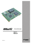
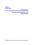
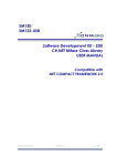
1
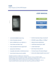
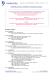
SME290-Mini
SME291
USER MANUAL & DATASHEET
SME29X – Serial Ethernet Family
Connects any serial device to LAN/WAN/Internet
True Serial-Ethernet Conversion. No Control Mechanism is required.
Plug & Play, no need for initializations in run-time.
Based on UDP protocol, 10BaseT
Wide input voltage range. On Board 5V regulator (SME291)
Serial/UART Interface up to 115200bps (57600bps Default)
One Static IP
Two type hardware alternatives:
Ethernet Module with RJ45 Connector or without RJ45 Connector
Configurable thru UART/RS232 or Ethernet (LAN)
Upgradeable with encrypted ROM images
Ideal for embedded applications
Ideal for existing serial devices
SME290-Mini
SME291
2
SME 290/291 Datasheet
1. INTRODUCTION .............................................................................................................. 3
2.
PINOUT INFORMATION.............................................................................................. 4
2.1 SME290-Mini Ethernet Module ......................................................................................... 4
2.1.1
SME290-Mini-EK Evaluation Kit Pinout View ..................................................................... 6
2.2 SME291 Ethernet Module ................................................................................................... 7
2.2.1
SME291-EK Evaluation Kit Pinout View .............................................................................. 8
3. SYSTEM CONNECTION ALTERNATIVES ...................................................................... 9
3.1 Network Connections Alternatives............................................................................... 10
3.1.1 Crossover Cable Connection ............................................................................................... 10
3.1.2 Standard Network Connection ............................................................................................ 11
4. CONFIGURATION & SOFTWARE TOOLS .................................................................. 13
4.1 SMUDP Search Software .................................................................................................. 13
4.2 SMSerial Configurator Software ..................................................................................... 15
4.3 UDP Data Terminal Software ........................................................................................... 16
4.3.1 Example Configuration ........................................................................................................... 17
5. MECHANICAL DRAWINGS & DIMENSIONS............................................................ 18
5.1 SME290-Mini Ethernet Module ....................................................................................... 18
5.2 SME291 Ethernet Module ................................................................................................. 19
5.3 SME2029C Connection Board ........................................................................................ 20
6. DC & ELECTRICAL CHARACTERISTICS ..................................................................... 21
ABSOLUTE MAXIMUM RATINGS ........................................................................................................ 21
DC CHARACTERISTICS ....................................................................................................................... 21
OPERATING TEMPERATURE ............................................................................................................... 21
SPECIFICATIONS .................................................................................................................................. 21
7. SALES AND SERVICE INFORMATION ....................................................................... 22
SonMicro Electronics
Revision A.2
May, 2008
3
SME 290/291 Datasheet
1. INTRODUCTION
This document gives detailed descriptions and instructions to use “Serial Ethernet” Module, Evaluation kit, and the Software tools based on “Serial
1.0” firmware version. For rapid development please go over this
document carefully.
SME290/291 Ethernet module is a true Serial-to-Ethernet converter that
connects a serial device to the LAN/WAN or internet based on UDP
protocol. Connection alternatives, depending on the software and
hardware of the system, are listed in Chapter 3.
SME290/291 does not require any external microcontroller or PC to be
controlled; it simply translates Ethernet and Serial data to each other with
the minimum latency.
SME290/291 Ethernet module can be used with existing serial devices
without any design change in hardware.
SME290/291 is very simple to use after getting know few main parameters
of the Ethernet network. The basic knowledge of Ethernet is described in
the following chapters.
SME290/291 is a very effective design that does not require any design
obstacles, and a serial device can be connected to the world just in
minutes.
SME290-Mini-EK / SME291-EK
Evaluation Kit for SME290/SME291 Ethernet Module
For rapid prototyping, demonstration or application development we
recommend you to buy a low cost evaluation kit from our online store at
www.sonmicro.com/shop/shop3.php
SME291-EK – Evaluation Kit
SonMicro Electronics
Revision A.2
May, 2008
4
SME 290/291 Datasheet
2. PINOUT INFORMATION
There are two hardware options are available for the Serial Ethernet
Module. Both versions programmed with the same firmware version.
2.1 SME290-Mini Ethernet Module
SME290-Mini is a DIP (2mm pin pitch) type module that can be plugged
into the PCB and is not integrated with RJ45 connector.
Please notice that:
SME290-Mini Modules can only work with LF1S022 RJ45 connectors.
LF1S022 is a RJ45 type Ethernet connector integrated with filters.
Designers can select this module if the Ethernet module is going to be
used on his/her Printed Circuit Board and the RJ45 connector will be
used in different place on the board. This is the flexible option.
1 RXD
RESET 28
2 TXD
RSV4 27
3 GND
ISSP-D 26
4 VCC
VCC 25
5 GND
ISSP-C 24
2.0 mm Pin Space
6 LED2
NC 23
7 LED1
GND 22
8 LED0
NC 21
9 TPIN+
RSV3 20
10 TPIN-
RSV2 19
11 VCC
NC 18
12 GND
VCC 17
13 TPOUT-
GND 16
14 TPOUT+
RSV1 15
SME290-Mini Ethernet Module PinOut View
SonMicro Electronics
Revision A.2
May, 2008
5
SME 290/291 Datasheet
PIN NUMBER
ASSIGNMENT
ELECTRICAL TYPE
DEFINITION
1
RXD
INPUT
UART / Serial Receive ( 0 -5V CMOS)
2
TXD
OUTPUT
UART / Serial Transmit (0 -5V CMOS)
3-5-12-16-22
GND
POWER
4-11-17-25
VCC
POWER
6
LED2
OUTPUT
Ethernet Transmit data status led
7
LED1
OUTPUT
Ethernet Receive data status led
8
LED0
OUTPUT
Ethernet Link or Collision status led
9
TPIN+
INPUT
Positive line of the differential input signal pair
10
TPIN-
INPUT
Negative line of the differential input signal pair
13
TPOUT-
OUTPUT
Negative line of the differential output signal pair
14
TPOUT+
OUTPUT
Positive line of the differential output signal pair
15-18-19-2021-23-24-26-27
NC
28
RST
Ground connections (all connected on module
internally)
Supply voltage (5V) (all connected on module
internally)
No connection
INPUT
Reset, (Active High)
SME290-Mini Pin Information
SonMicro Electronics
Revision A.2
May, 2008
6
SME 290/291 Datasheet
2.1.1 SME290-Mini-EK Evaluation Kit Pinout View
SME290-Mini-EK Front View
SME290-Mini-EK Layout View
SonMicro Electronics
Revision A.2
May, 2008
7
SME 290/291 Datasheet
2.2 SME291 Ethernet Module
SME291 is a compact module integrated with 5V regulator circuit and the
LF1S022 RJ45 Ethernet connector. SME291 module may be used apart
from the device or PCB. It requires only Power Supply pins and UART TX/RX
pins to the main device or circuit. This is the more practical option if
compared with SME290 module. SME291 can be used inside the product
enclosure or can be connected externally.
SME291 – Ethernet Module Pinout View
SonMicro Electronics
Revision A.2
May, 2008
8
SME 290/291 Datasheet
2.2.1 SME291-EK Evaluation Kit Pinout View
Please note that SME291 module and connection board can easily be
separated from each other by removing jumpers shown in the figure.
Connection Board includes MAX232/ST232 level converter chip and DC
adapter input for easy connection with PC or external device over RS232
bus.
SME291-EK – Evaluation Kit Pinout View
SonMicro Electronics
Revision A.2
May, 2008
9
SME 290/291 Datasheet
3. SYSTEM CONNECTION ALTERNATIVES
SME290/291 Ethernet module with “Serial 1.0” firmware version uses UDP
protocol as main Ethernet protocol.
For new software designs; using a UDP socket or SonMicro UDP ActiveX
Control is recommended.
For existing RS232 software, 3Rd party UDP Redirector software tools can be
used, or another Ethernet module can be used in PC side for UDP to Serial
conversion.
Software Development Kit, SDK, is available with deluxe version of the
Ethernet Evaluation Kits. SDK includes example code written in Delphi,
Visual Basic, C #.Net and comes with UDP ActiveX Control to simplify
software writing.
Serial Device
(RS232 / UART)
LAN/WAN/Internet
Software uses UDP Socket
to communicate.
UDP Redirector or ActiveX
Control can be used for
easy UDP access
UDP is very similar to Com port. It is very
easy to send and receive data packets over UDP
Basic Ethernet Connection System
SonMicro Electronics
Revision A.2
May, 2008
10
SME 290/291 Datasheet
In the below alternative connection diagram, there is no need to use
Ethernet communication in the software. Both devices can communicate
each other with serial/RS232 protocol.
Serial Device
(RS232 / UART)
LAN/WAN/Internet
RS232 Software
Software uses Serial Port
Alternative Connection System (PC can be replaced with a serial device)
3.1 Network Connections Alternatives
Before starting with the communication examples, network should be
properly setup. There are two alternatives to connect your device to
LAN; connecting the SME290-Mini-EK / SME291-EK Kit PC with crossover
cable or the existing Hub/Router with a standard RJ-45 Ethernet cable.
3.1.1 Crossover Cable Connection
The following figure is a crossover cable connection diagram. If you
don’t have a Hub and want to connect your device to LAN thru your
PC, you need a crossover cable.
Crossover Cable
SonMicro Electronics
Revision A.2
May, 2008
11
SME 290/291 Datasheet
Please notice that:
Standard RJ-45 Ethernet cable connection is used only to connect
SME290-Mini-EK / SME291-EK Kit to a Hub/Ethernet switch or Router
device. For direct PC connection only crossover cable will work.
Following is the connection of SME290-EK Development Kit to the PC
with crossover cable.
RJ-45 Ethernet
Crossover Cable
Serial Port Cable
(USB Serial Converter)
Direct PC Connection with Crossover Cable
3.1.2 Standard Network Connection
Local Area Networks consist of Routers/Hubs to connect multiple
devices in the LAN. To connect SME290-Mini-EK / SME291-EK Kit to the
Hub, standard RJ-45 Ethernet Data cable is required. Connecting the
Ethernet Kit to the Hub with Crossover Cable will not work.
Standard RJ-45 Ethernet Cable
SonMicro Electronics
Revision A.2
May, 2008
12
SME 290/291 Datasheet
Followings are the connection diagrams of SME290-EK Development kit
to the Hub or Wireless router. Note that serial connection can be made
to a PC or external MCU with UART pins. PC does not need to be
connected to the LAN, it can only control module to send data to
another device in the LAN or Internet.
HUB
Standard RJ-45
Ethernet Cable
Standard RJ-45
Ethernet Cable
Serial Port Cable
or
USB Serial Converter
Standard Network Connection Example with Router/Hub
Standard RJ-45
Ethernet Cable
Standard RJ-45
Ethernet Cable
Serial Port Cable
or
USB Serial Converter
Standard Network Connection Example with Wireless Router/Hub
SonMicro Electronics
Revision A.2
May, 2008
13
SME 290/291 Datasheet
4. CONFIGURATION & SOFTWARE TOOLS
SME290-Mini / SME291 Ethernet module can be configured thru serial port
or remotely configured thru UDP in the LAN.
Once the configuration is done, Ethernet module will be ready for
Ethernet-serial translation. In run time changing network parameters is
possible by external microcontroller. This can be used to change remote
IP, Remote Port parameters for the Ethernet module to connect another
device.
4.1 SMUDP Search Software
SMUDP Search software is used to detect all SonMicro Ethernet modules in
the same LAN and allow changing configuration parameters of the
modules.
Configuration by UDP is very useful when the module is integrated with the
customer product and it is hard to configure each module by RS232.
SMUDP Search Software Snapshot
To search for the available SonMicro Ethernet Modules in the LAN click on
the Search Device button. It may be necessary to try few times. Selected
Ethernet module parameters will be available in the Parameters section.
After changing parameters if required, SET PARAMETERS button should be
clicked to apply the changes.
SonMicro Electronics
Revision A.2
May, 2008
14
SME 290/291 Datasheet
Gateway IP:
GATEWAY IP Address is the IP address of the router or
device that connects your network devices to Wide Area Network or
Internet. It is a gate/door that opens into WAN or another LAN. When
sending data to devices in WAN or Internet, you need GATEWAY IP
address to exit from Local Area Network.
Subnet Mask:
This should be same SUBNET MASK used in the LAN. Check
the Router’s or Gateway’s configuration to get the SUBNET MASK used.
Most LANs uses 255.255.255.0 for SUBNET MASK. By this way 255 devices
can be connected to one LAN. If SUBNET MASK is 255.255.0.0 it means
255*255(65025) device can be connected to the same LAN. If the Subnet
Mask of the network and the device does not match then connection
may not be established with that device.
Module IP:
This is the Local IP address of the module. The IP number
entered into this field should be unique in the LAN otherwise
communicating with the device may not be possible. IP address of the
module should consistent with the LAN properties. For example, when the
Gateway IP address is 192.168.1.1 and the subnet is 255.255.255.0, then the
Module IP address must be within 192.168.1.2 – 192.168.1.255
Module Port:
This is the UDP port of the module is listening to. Remote
device will connect to this port. If Ethernet Module is going to be
accessed outside of the LAN and if there is a firewall or router in the LAN,
this port should be directed to Module IP address in the security / virtual
server settings of the Gateway /firewall device. Otherwise incoming data
packets from WAN/Internet will not rout to the Ethernet module. In this
situation, where there are incoming data packets outside of the LAN, if
there are multiple modules, every module should have different port
number so that firewall/gateway can route the incoming data packets to
the right device. Module port number can be between 0 – 65535.
Remote IP:
This is the IP address of the remote device to which
module will send data. If the remote device is outside of the LAN, then
gateway setting should be adjusted properly.
Remote Port:
This is the UDP port number of the remote device to which
module will send data. If the remote device is outside of the LAN, then
gateway setting should be adjusted properly. Remote Port and module
port can be the same. Remote port number can be between 0-65535.
Password/Key: This is a 10 digit special key used to put the module into
configuration mode. When this key is sent to the module over UART
module will enter into configuration mode thus this data will not be
transmitted over Ethernet. Default password/key is “*SONMicro*”
SonMicro Electronics
Revision A.2
May, 2008
15
SME 290/291 Datasheet
Baudrate:
Serial Baud rate of the device can be changed.
Available alternatives are 9600bps, 19200bps, 57600bps, 115200bps, N, 8,1
Custom baud rates are available upon request.
4.2 SMSerial Configurator Software
SMSerial Configurator software is used to configure Ethernet module over
RS232/serial bus.
SMSerial Configurator Snapshot
Before reading/changing parameters, module needs to be put into
configuration mode. This is done by clicking on Enter Configuration button.
This button will simply send the PASSWORD/KEY to the module. This special
10 digit character set, will put the module into configuration mode.
SonMicro Electronics
Revision A.2
May, 2008
16
SME 290/291 Datasheet
4.3 UDP Data Terminal Software
This software is a basic UDP Data terminal. You can send and receive UDP
data packets. It is a useful tool to test the communication, or establish
communication with the remote device. For example if you have a serial
device to control, you can send data or commands from UDP Terminal
then the Ethernet module will convert UDP data to serial.
UDP Data Terminal Software Snapshot
SonMicro Electronics
Revision A.2
May, 2008
17
SME 290/291 Datasheet
Remote IP:
This is the IP address of the remote device to which data
is send. If communicating with a serial device with Ethernet module is
connected then the Remote IP should be the IP address of the module.
Remote UDP Port: This is the UDP port number of the remote device to
which data is send. If communicating with a serial device with Ethernet
module is connected then the Remote Port should be the Port number of
the Ethernet Module.
Host UDP Port: This is the UDP port number of the PC/Host listening.
Remote device need to send data packets to this port. In our case,
Remote Port of the Ethernet Module should be Host UDP Port so that
module can send data to this port and PC listens at this port.
4.3.1 Example Configuration
Module IP = 192.168.1.102
Ethernet Cable / Connection
LAN/WAN/Internet
Ethernet Cable /
Connection
Serial Cable/Connection
Serial Device
(RS232 / UART)
Host / PC IP = 192.168.1.22
Se tting in Etherne t Module
Se ttings in UDP Te rmina l
Module
Module
Module
Module
Re mote IP
= 192.168.1.102 (Module IP)
Re mote Port
= 6000 (Module Port)
Hos t UDP Port = 7000(Module Remote Port)
IP
=192.168.1.102
Port
= 6000
Remote Port = 7000
Remote IP = 192.168.1.22
Example Settings
SonMicro Electronics
Revision A.2
May, 2008
18
SME 290/291 Datasheet
5. MECHANICAL DRAWINGS & DIMENSIONS
All dimensions are in millimeters (mm) with ± 0.3mm tolerance
5.1 SME290-Mini Ethernet Module
Dimensions in millimeters
SonMicro Electronics
Revision A.2
May, 2008
19
SME 290/291 Datasheet
5.2 SME291 Ethernet Module
Dimensions in millimeters
SonMicro Electronics
Revision A.2
May, 2008
20
SME 290/291 Datasheet
5.3 SME2029C Connection Board
Dimensions in millimeters
SonMicro Electronics
Revision A.2
May, 2008
21
SME 290/291 Datasheet
6. DC & ELECTRICAL CHARACTERISTICS
ABSOLUTE MAXIMUM RATINGS
Symbol
Description
Min
Typ
Max
Units
Notes
TSTG
Storage Temperature
-55
-
100
°C
Higher storage temperatures will reduce
data retention time
TA
Ambient
Temperature
0
-
70
°C
VCC
Supply Voltage
-0.5
5
5.5
V
IMIO
Maximum
Current
into any Port Pin
-25
-
25
mA
ESD
Electro
Static
Discharge Voltage
2000
-
-
V
Human Body Model ESD
9-12VDC available at different input pins
for SME291. (On board 5V regulator)
DC CHARACTERISTICS
Symbol
Description
Min
Typ
Max
Units
Notes
VCC
Supply Voltage
4.75
5.00
5.25
V
9-12VDC available at different input pin
for SME291. (On board 5V regulator)
IO
Supply Current
20
30
80
mA
Table 3 – DC Characteristics
OPERATING TEMPERATURE
Symbol
Description
Min
Typ
Ma
x
Unit
s
TA
Ambient
Temperature
0
-
70
°C
TJ
Junction
Temperature
0
-
85
°C
Notes
SPECIFICATIONS
Parameter
Notes
Ethernet interface
10BaseT Ethernet
Serial interface
CMOS-level; TX, RX, and GND
Serial communication speed
Maximum Data buffer for each Ethernet data segment
9600 bps, 19200 bps, 57600 bps,115200 bps
726 Bytes at one time
SonMicro Electronics
Revision A.2
May, 2008
22
SME 290/291 Datasheet
7. SALES AND SERVICE INFORMATION
To obtain information about SonMicro Electronics products and technical support,
reference the following information.
SonMicro Electronics LTD.
Cankaya M. Soguksu C.
Aslihan Ishani 2/15
Mersin, 33070
TURKIYE
Phone:
Facsimile:
Email:
Web Site:
+90 324 237 21 28
+90 324 237 21 86
[email protected]
http://www.sonmicro.com
Sales
Support
Documents & Software
User Forums
SonMicro Electronics
http://www.sonmicro.com/sales.php
http://www.sonmicro.com/contact.php
http://www.sonmicro.com/eth/deth.php
http://www.sonmicro.com/forums/
Revision A.2
May, 2008