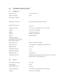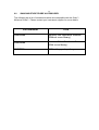
1
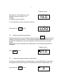
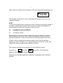
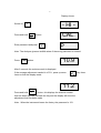
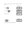
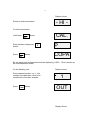
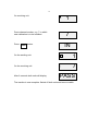
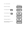
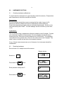
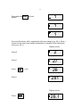
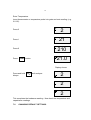
SINAR TECHNOLOGY MOISTURE PROBE USER MANUAL. Read all instructions prior to operating your Sinar Moisture Probe. Whenever using this unit, remember to follow the appropriate operating procedures. For your reference/record: Serial Number: Purchase Date: Date Registration Card Mailed: Moisture Probe. Rev. 3. 11/10 For Version 1.2 software. Sinar Technology Unit 5, Camberley Business Centre, Bracebridge, Camberley, Surrey. GU15 3DP ENGLAND Tel: 0844 745 1999 Tel International: +44 208 328 0727 Fax: +44 (0) 1276-29941 Email: [email protected] Website: www.sinar.co.uk 2 Sinar Moisture Probe. Model 6600 The performance of this Moisture Analyser is dependent on the correct use and instrument care by the customer. It is important to check the calibration (both commodity and hardware) periodically and, if necessary, make adjustments following the procedure in this manual. The commodity calibration can be checked by comparing the Moisture Analyser results against reference samples, e.g. oven tested samples (please ensure that tested samples are based on the correct oven test specification). CONTENTS 3 1.0 INTRODUCTION. 4 2.0 BASIC PRINCIPLE OF OPERATION 4 3.0 OPERATING INSTRUCTIONS 3.1 Taking a single moisture content reading. 3.2 Taking continuous moisture content readings. 3.3 Measuring sample temperature. 3.4 Using the average moisture content facility. 5 5 5 6 6 4.0 CALIBRATION ADJUSTMENTS. 4.1 % moisture content. 7 7 5.0 CALIBRATION TRANSFERS. 5.1 Remote access mode. 5.2 Continuous mode. 5.2.1 Single curve transfer. 5.2.2 CURVE SET TRANSFER. 10 10 10 10 13 6.0 HARDWARE SECTION. 6.1 Checking hardware calibrations. 6.2 Resetting hardware. 14 14 14 7.0 16 CHANGING DEFAULT SETTINGS. 8.0 TECHNICAL SPECIFICATION. 8.1 Display unit. 8.2 Sensor. 19 19 19 9.0 20 SINAR MOISTURE PROBE ACCESSORIES. 4 1.0 INTRODUCTION. The Sinar Moisture Probe, moisture Analyser houses the latest moisture measuring technology in a compact package. It has been designed to provide fast moisture results using whole grain samples. In addition to % moisture content, the Moisture Probe also measures temperature. Each instrument is pre-calibrated for up to seven commodities either chosen from a standard package of programmes or selected from the Sinar calibration library. The calibration of any product can be optimised using a bias facility. The Sinar Moisture Probe is one of a family of moisture analysers. All models have the facility to transfer and receive calibrations either from each other, via a Sinar Acoustic Coupler and telephone link or via the Internet. Similarly new commodities can be transferred or existing calibrations can be updated with new information. The Sinar Moisture Probe has been calibrated using clean samples. Accuracy can be affected by the presence of stones, dirt, weeds, seeds, admixture, chaff or other foreign matter. Clean the sensor with a soft brush to prevent material build-up on the fins. NEVER USE WATER. Take care not to damage the temperature sensor. 2.0 BASIC PRINCIPLE OF OPERATION The design concept of the Sinar Moisture Probe is based on the simultaneous sensing of capacitance and temperature of the sample being tested, providing a corrected moisture (%) reading in a few seconds. It works accurately on products with a moisture content ranging from approximately 1% to 35% depending on the application. The instrument incorporates 2 sensors: 1. Capacitance The moisture in a sample absorbs the electrical energy between the sensor fins. The electrical signal known as "Capacitance" increases with the moisture content of the sample. 2. Temperature Correction The capacitance of a sample increases with temperature. A temperature sensing thermistor is mounted in the sample cell and the microprocessor carries out an automatic correction. Sinar refer to a capacitance reading corrected for temperature as a code 0 reading. 5 3.0 OPERATING INSTRUCTIONS Hold the display unit in one hand. Hold the spear via the black “mushroom” cap in the other hand. Select the required crop as detailed below. Insert the spear sensor into the crop ensuring that the black sensor fins are completely covered. We recommend the sensor is inserted to a consistent depth to give a consistent packing density of crop around the sensor. Proceed as detailed below. 3.1 Taking a single moisture content reading. Display shows. Switch on I Select channel 1-7 e.g. 2. Press %H20 button. Moisture content - HI 2 14.5 will be displayed after 5 seconds. 3.2 Taking continuous moisture content readings. Display shows. Switch on I Select channel 1-7 e.g. 2. Press and hold %H20 button. - HI 2 LOG 6 Display shows. After approx. 5 seconds the unit will display a moisture reading. The reading is updated every 4 seconds. 14.5 To end continuous mode, proceed as follows:- Press and hold %H20 button. 3.3 -LOG Measuring sample temperature. TEMP Sample temperature can be measured by pressing the button when the sample is covering the sensor. If the sample temperature is very different from the ambient temperature, leave the sample for 30 seconds before you press TEMP. Alternatively, keep on pressing the TEMP button, until a stable temperature is displayed. Display shows. Press TEMP button. 3.4 21.0 Using the average moisture content facility. A maximum of 254 samples can be averaged. It the AVER button is held down, the display will show the number of measurements that have been made, e.g. Press and hold AVER button. 3 7 When this key is released, the average % moisture content will be displayed, e.g. 10.6 The average can be reset to zero by switching the analyser off and on or by changing channels. NOTE. If using the average function ensure the sensor is always covered with sample. If a reading is taken with the sensor half covered, the reading will added to the average stack and effect the accuracy of the final result. 4.0 CALIBRATION ADJUSTMENTS. 4.1 % moisture content. Sometimes it is useful to be able to adjust the moisture reading, for instance, when a different oven test is used, or when the particle size of a product is significantly different, or when 2 instruments are checked against each other. However, before adjusting the moisture reading, check that the hardware settings are correct. (Section. 6.1). Having done this surround the sensor with sample and select the appropriate calibration channel. The moisture reading may be adjusted for each individual channel using the up and down arrow keys. The adjustment applies to all points of the selected channel. Determine the average adjustment needed by comparing at least 3 different samples. 8 Display shows. Switch on - HI - I CAL Press and hold AUTO button. auto Enter password and press P CAL. P Note: The Analyser gives an audible alarm if the wrong password is entered. Press %H20 10.9 button. After 5 seconds the moisture result is displayed. If the average adjustment needed is +0.3%, press up arrow times so that the display reads: 11.2 Press and hold lb/bu kg/hl button, this displays the channel number that has been adjusted. Release the key and the display will show the adjustment that has been made. Note: When the instrument leaves the factory the password is 123. key three 9 In order to check to see whether a channel has been adjusted, proceed as follows: Display shows. Switch on - HI - I CAL Press and hold AUTO button. auto Select channel, e.g. 1. CAL. 1 Display shows. Press lb/bu kg/hl button. (0.0 means that no adjustment has been made). 0.0 10 5.0 CALIBRATION TRANSFERS. 5.1 Remote access mode. The Moisture Probe can be put into remote access mode or “PLUG” mode. This is a remote mode to enable calibration data to be imported or exported from the Moisture Probe to a PC with the Sinar MNET (Pt No 1900-6309) software installed. Data can also be transmitted via telephone line using the Sinar Acoustic Coupler (Pt No 6230-001). Display shows. Press and hold the TEMP button while switching on I ---PLUg - HI - All operations are now carried out via the PC. 5.2 Continuous mode. The following instructions relate to communicating with a Sinar AP moisture instrument only. Details of communications with other models are included in their respective user manuals. 5.2.1 Single curve transfer. In order to transfer one calibration to an AP analyser, proceed as follows: Ensure both units are switched off. Connect the Sinar calibration transfer cable (Pt No 1000-2766) to the RS232 port on the left hand side of the Moisture Analysers. 11 Display shows. - HI - Switch on both instruments. For both instruments: Hold down CAL AUTO auto Enter password and press button. Press CAL AUTO auto CAL. button. P button. P COPA By this stage both instruments should be displaying COPA. (This is known as the communication mode). On the Sending Unit. Press channel number, e.g. 1, this contains the calibration curve to be transferred to the other analyser. Press %H20 button. Display shows. 1 OUT Display Shows. 12 On receiving unit. Press channel number, e.g. 7 in which new calibration is to be installed. Press AVER button. 1 7 IN On the sending unit. 1 On the receiving unit. 7 After 6 seconds both units will display PASS The transfer is now complete. Switch off both units and remove cable. 13 5.2.2 Curve set transfer. Display shows. Set both units to display. On the sending unit press %H20 COPA OUT Display shows. On the receiving unit press AVER Sending unit changes to - Receiving unit changes to - When the transfer is completed both instruments will display IN OUT IN PASS 14 6.0 HARDWARE SECTION. 6.1 Checking hardware calibrations. To check that the instrument is in good working order the sensors, (Temperature and Capacitance) should be checked as follows: Temperature: Pour the sample around the sensor covering the fins totally. Leave for 30 seconds so that the sample and sensor temperature reach equilibrium. Check the temperature of grain using an accurate thermometer. Switch on the instrument and press TEMP. The two readings should not differ by more than 1.5°C. Capacitance: This is checked using a capacitance reference sample (code 0 sample). Contact your instrument supplier for this sample. Pour the sample around the sensor covering the fins. Press the 0 button and then the %H20 button. The displayed result should be no greater than ±0.3 from the value of the code 0 sample. The code 0 value is written on the side of the sample container. If any of these measurements are out of tolerance, the instrument should be recalibrated. 6.2 Resetting hardware. Ensure there is no sample around the sensor. Display shows. Switch on - HI - I CAL Press and hold AUTO button. auto Enter password and press P. CAL. P CAL Press and hold AUTO button. auto HCAL 15 Press and hold AVER until unit bleeps. 1 1 1 Surround the sensor with a capacitance reference sample (e.g. 28.1). Allow 1 minute for the sensor and sample temperature to equalise. Enter Reference Value (e.g. 28.1). Display shows. 2 Press 2 Display shows. 27 Press 7 Press once. 28 281 Press 1. Display shows. Press lb/bu kg/hl 28.1 16 Enter Temperature. Insert thermometer or temperature probe into grain and note reading, (e.g. 21.0°C). Press 2 2 Press 1 21 Press 0 210 Press TEMP button. 21.0 Display shows. Press and hold %H20 until analyser bleeps. 2 2 2 This completes the hardware resetting. Now check the temperature and capacitance readings. 7.0 CHANGING DEFAULT SETTINGS. 17 The following options are available: a) Temperature - °C or °F. b) Baud rate setting of 300 or 4800. c) High or low frequency moisture measurement. The procedure to change from one default setting to the other is as follows: Display shows. Switch on - HI - I Press and hold CAL AUTO auto button. Enter password and press Press CAL AUTO auto button. P CAL. P COPA Display shows. Press CAL AUTO auto button again. SEt 18 In this mode the following keys have specific functions: TEMP When this key is held down, the display changes from USA to Euro or vice versa. In Euro units the readings are °C for temperature. In USA units, the readings are °F for temperature. AVER When this key is held down the baud rate changes from 300 to 4800 or vice versa. 19 8.0 TECHNICAL SPECIFICATION. 8.1 Display unit. Dimensions (mm): H195 x W154 x D33 Display Unit Weight: 0.6 KG Max. Number of Sensors: 1 Display Unit Construction: Fabricated aluminium alloy, powder coated. Operating Environment: 0 to +55 °C. Storage Temperature: -20 °C to +55 °C; Humidity to 95% non condensing. Humidity: Up to 95% non condensing. Display: 3.5 character 20mm LCD. Processor: Intel 80C31 microprocessor. Memory: EPROM and RAM Calibrations supplied. (Upgradable via the RS232 port). 7 Max. calibration capacity: 7 Data Output Format: RS232 C, ASCII code, 300 Baud. Moisture Accuracy: ± 0.5% dependant on application and moisture level. Readout Interval. 4 seconds. Temperature Accuracy: ± 1 °C. Displayed Temperature: °C or °F Display Resolution: 1 Decimal place. Temperature Correction: Temperature sensor mounted on fin. Correction factor is software programmable. Correction range 0-40 °C. 8.2 Sensor. Sensor Dimensions (mm): ∅80 x 380 Sensor Weight: 0.8 KG Operating Environment: 0 to +65°C. Storage Temperature: -20 °C to +80 °C; Humidity to 95% non condensing. Humidity: Up to 95% non condensing. 20 9.0 SINAR MOISTURE PROBE ACCESSORIES. The following are a list of accessories which are compatible with the Sinar Moisture Probe. Please contact your instrument supplier for more details. Part Number Title 1900-6309 Moisture Net calibration software. (Without curve library). 1900-6229 Moisture Net calibration software. (With curve library). 19006940 F4 Email upgrade package