1
PROGRAMMING
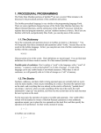
IsoMax™ is a programming language based on Finite State Machine (FSM) concepts
applied to software, with a procedural language (derived from Forth) underneath it. The
closest description to the FSM construction type is a “One-Hot” Mealy type of Timer
Augmented Finite State Machines. More on these concepts will come later.
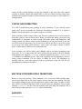
QUICK OVERVIEW
What is IsoMax™? IsoMax™ is a real time operating system / language.
How do you program in IsoMax™? You create state machines that can run in a virtually
parallel architecture.
Step
1
Programming Action
Name a state machine
Syntax
2
Select this state
ON-MACHINE <name>
3
Name any states appended on the machine
APPEND-STATE <name>
APPEND-STATE <name>
…
4
Describe transitions from states to states
IN-STATE
MACHINE <name>
<state>
CONDITION
<Boolean>
CAUSES
<action>
THEN-STATE
<state>
TO-HAPPEN
5
Test and Install
{as required}
What do you have to write to make a state machine in IsoMax™? You give a machine a
name, and then tell the system that’s the name you want to work on. You append any
number of states to the machine. You describe any number of transitions between states.
Then you test the machine and when satisfied, install it into the machine chain.
What is a transition? A transition is how a state machine changes states. What’s in a
transition? A transition has four components; 1) which state it starts in, 2) the condition
necessary to leave, 3) the action to take when the condition comes true, and 4) the state to
go to next time. Why are transitions so verbose? The structure makes the transitions easy
to read in human language. The constructs IN-STATE, CONDITION, CAUSES, THENSTATE and TO-HAPPEN are like the five brackets around a table of four things.
IN-STATE
\
CONDITION
/\
<from state>
CAUSES
/\
<Boolean>
THEN-STATE
/\
<action>
TO-HAPPEN
/
<to state>
In a transition description the constructs IN-STATE, CONDITION, CAUSES, THEN-STATE
and TO-HAPPEN are always there (with some possible options to be set out later). The
“meat slices” between the “slices of bread” are the hearty stuffing of the description. You
will fill in those portions to your own needs and liking. The language provides “the
bread” (with only a few options to be discussed later).
So here you have learned a bit of the syntax of IsoMax™. Machines are defined, states
appended. The transitions are laid out in a pattern, with certain words surrounding others.
Procedural parts are inserted in the transitions between the standard clauses.
The syntax is very loose compared to some languages. What is important is the order or
sequence these words come in. Whether they occur on one line or many lines, with one
space or many spaces between them doesn’t matter. Only the order is important.
THREE MACHINES
Now let’s take a first step at exploring IsoMax™ the language by looking at some very
simple examples. We’ll explore the language with what we’ve just tested earlier, the LED
words. We’ll add some machines that will use the LED’s as outputs, so we can visually
“see” how we’re coming along.
REDTRIGGER
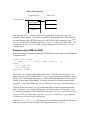
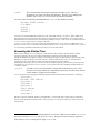
First let’s make a very simple machine. Since it is so short, at least in V0.3 and later, it’s
presented first without detailed explanation, entered and tested. Then we will explain the
language to create the machine step by step
MACHINE REDTRIGGER ON-MACHINE REDTRIGGER APPEND-STATE RT
IN-STATE RT CONDITION PA7 OFF? CAUSES REDLED ON THEN-STATE RT TO-HAPPEN
RT SET-STATE ( INSTALL REDTRIGGER
EVERY 50000 CYCLES SCHEDULE-RUNS REDTRIGGER
There you have it, a complete real time program in two lines of IsoMax™, and few
additional lines to install it. A useful virtual machine is made here with one state and one
transition.
This virtual machine acts like a non-retriggerable one-shot made in hardware. (NONRETRIGGERABLE ONE-SHOT TIMER: Produces a preset timed output signal on the
occurrence of an input signal. The timed output response may begin on either the leading
edge or the trailing edge of the input signal. The preset time (in this case: infinity) is
independent of the duration of the input signal.) For an example of a hardware nonretriggerable one-shot, see http://www.philipslogic.com/products/hc/pdf/74hc221.pdf.
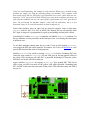
If PA7 goes low briefly, the red LED turns on and stays on even if PA7 then changes.
PA7 normally has a pull up resistor that will keep it “on”, or “high” if nothing is attached.
So attaching push button from PA7 to ground, or even hooking a jumper test lead to
ground and pushing the other end into contact with the wire lead in PA7, will cause PA7
to go “off” or “low”, and the REDLED will come on.
(In these examples, any port line that can be an input could be used. PA7 here, PB7 and
PB6 later, were chosen because they are on J1 and the easy to access.)
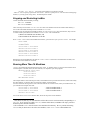
Now if you want, type these lines shown above in. (If you are reading this manual
electronically, you should be able to highlight the text on screen and copy the text to the
clipboard with Cntl-C. Then you may be able to paste into your terminal program. On
MaxTerm, the command to down load the clipboard is Alt-V. On other windows
programs it might be Cntl-V.)
Odds are your red LED is already on. When the ServoPod-USB™ powers up, it’s
designed to have the LED’s on, unless programmed otherwise by the user. So to be useful
we must reset this one-shot. Enter:
REDLED OFF
Now install the REDTRIGGER by installing it in the (now empty) machine chain.
RT SET-STATE ( INSTALL REDTRIGGER
EVERY 50000 CYCLES SCHEDULE-RUNS REDTRIGGER
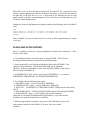
Ground PA7 with a wire or press the push button, and see the red LED come on. Remove
the ground or release the push button. The red LED does not go back off. The program is
still running, even though all visible changes end at that point. To see that, we’ll need to
manually reset the LED off so we can see something happen again. Enter.
REDLED OFF
If we ground PA7 again, the red LED will come back on, so even though we are still fully
interactive with the ServoPod-USB™ able to type commands like REDLED OFF in
manually, the REDTRIGGER machine is running in the background.
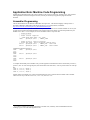
Now let’s go back through the code, step-by-step. We’ll take it nice and easy. We’ll take
the time explain the concepts of this new language we skipped over previously.
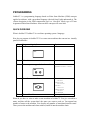
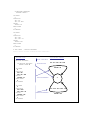
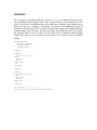
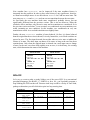
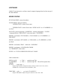
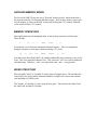
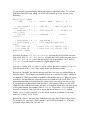
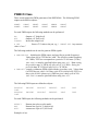
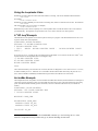
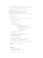
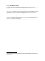
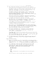
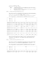
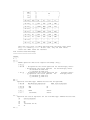
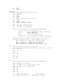
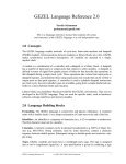
Here in this box, the code for REDTRIGGER “pretty printed” so you can see how the
elements of the program relate to a state machine diagram. Usually you start to learn a
language by learning the syntax, or how and where elements of the program must be
placed. The syntax of the IsoMax™ language is very loose. Almost anything can go on
any line with any amount of white space between them as long as the sequence remains
the same. So in the pretty printing, most things are put on a separate line and have spaces
in front of them just to make the relationships easy to see. Beyond the basic language
syntax, a few words have a further syntax associated to them. They must have new names
on the same line as them. In this example, MACHINE, ON-MACHINE and APPEND-STATE
require a name following. You will see that they do. More on syntax will come later.
PROGRAM TEXT
EQUIVALENT GRAPHIC
MACHINE REDTRIGGER
MAKE A MACHINE
ON-MACHINE REDTRIGGER
APPEND-STATE RT
IN-STATE
RT
CONDITION
PA7 OFF?
CAUSES
REDLED ON
THEN-STATE
RT
TO-HAPPEN
BOOLEAN
PA7 OFF?
ADD A STATE
REDLED ON
ACTION
ADD A TRANSITION
FROM STATE
RT
TO STATE
In this example, the first program line, we tell IsoMax™ we’re making a new virtual
machine, named REDTRIGGER. (Any group of characters without a space or a backspace
or return will do for a name. You can be very creative. Use up to 32 characters. Here the
syntax is MACHINE followed by the chosen name.)
MACHINE REDTRIGGER
That’s it. We now have a new machine. This particular new machine is named
REDTRIGGER. It doesn’t do anything yet, but it is part of the language, a piece of our
program.
For our second program line, we’ll identify REDTRIGGER as the machine we want to
append things to. The syntax to do this is to say ON-MACHINE and the name of the
machine we want to work on, which we named REDTRIGGER so the second program line
looks like this:
ON-MACHINE REDTRIGGER
(Right now, we only have one machine installed. We could have skipped this second line.
Since there could be several machines already in the ServoPod-USB™ at the moment, it
is good policy to be explicit. Always use this line before appending states. When you
have several machines defined, and you want to add a state or transition to one of them,
you will need that line to pick the machine being appended to. Otherwise, the new state
or transition will be appended to the last machine worked on.)
All right. We add the machine to the language. We have told the language the name of
the machine to add states to. Now we’ll add a state with a name. The syntax to do this is
to say APPEND-STATE followed by another made-up name of our own. Here we add
one state RT like this:
APPEND-STATE RT
States are the fundamental parts of our virtual machine. States help us factor our program
down into the important parts. A state is a place where the computer’s outputs are stable,
or static. Said another way, a state is place where the computer waits. Since all real time
programs have places where they wait, we can use the waits to allow other programs to
have other processes. There is really nothing for a computer to do while its outputs are
stable, except to check if it is time to change the outputs.
(One of the reasons IsoMax™ can do virtually parallel processing, is it never allows the
computer to waste time in a wait, no backwards branches allowed. It allows a check for
the need to leave the state once per scheduled time, per machine.)
To review, we’ve designed a machine and a sub component state. Now we can set up
something like a loop, or jump, where we go out from the static state when required to do
some processing and come back again to a static wait state.
The rules for changing states along with the actions to do if the rule is met are called
transitions. A transition contains the name of the state the rule applies to, the rules called
the condition, what to do called the action, and “where to go” to get into another state.
(We have only one state in this example, so the last part is easy. There is no choice. We
go back into the same state. In machines with more than one state, it is obviously
important to have this final piece.)
There’s really no point in have a state in a machine without a transition into or out of it. If
there is no transition into or out of a state, it is like designing a wait that cannot start,
cannot end, and cannot do anything else either.
On the other hand, a state that has no transition into it, but does have one out of it, might
be an “initial state” or a “beginning state”. A state that has a transition into it, but doesn’t
have one out of it, might be a “final state” or an “ending state”. However, most states will
have at least one (or more) transition entering the state and one (or more) transition
leaving the state. In our example, we have one transition that leaves the state, and one
that comes into the state. It just happens to be the same one.
Together a condition and action makes up a transition, and transitions go from one
specific state to another specific state. So there are four pieces necessary to describe a
transition; 1) The state the machine starts in. 2) the condition to leave that state 3) the
action taken between states and 4) the new state the machine goes to.
Looking at the text box with the graphic in it, we can see the transitions four elements
clearly labeled. In the text version, these four elements are printed in bold. In the
equivalent graphic they are labeled as “FROM STATE”, “BOOLEAN”, “ACTION” and
“TO STATE”.
The “FROM STATE” is RT. The “BOOLEAN” is a simple phrase checking I/O PA7
OFF?. The “ACTION” is REDLED ON. The “TO STATE” is again RT.
So to complete our state machine program, we must define the transition we need. The
syntax to make a transition, then, is to fill in the blanks between this form: IN-STATE
<name> CONDITION <Boolean> CAUSES <action> THEN-STATE <name> TO-HAPPEN.
Whether the transition is written on one line as it was at first:
IN-STATE RT CONDITION PA7 OFF? CAUSES REDLED ON THEN-STATE RT TO-HAPPEN
Or pretty printed on several lines as it was in the text box:
IN-STATE
RT
CONDITION
PA7 OFF?
CAUSES
REDLED ON
THEN-STATE
RT
TO-HAPPEN
The effect is the same. The five bordering words are there, and the four user supplied
states, condition and action are in the same order and either way do the same thing.
After the transition is added to the program, the program can be tested and installed as
shown above.
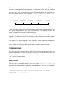
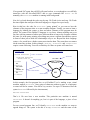
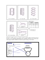
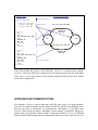
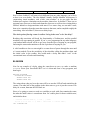
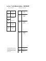
State machine diagrams (the graphic above being an example) are
nothing new. They are widely used to design hardware. They come
with a few minor style variations, mostly related to how the
outputs are done. But they are all very similar. The figure to the
right is a hardware Quadrature design with four states.
While FSM diagrams are also widely known in programming as an abstract
computational element, there are few instances where they are used to design software.
Usually, the tools for writing software in state machines are very hard to follow. The
programming style doesn’t seem to resemble the state machine design, and is often a
slow, table-driven “read, process all inputs, computation and output” scheme.
IsoMax™ technology has overcome this barrier, and gives you the ability to design
software that looks “like” hardware and runs “like” hardware (not quite as fast of course,
but in the style, or thought process, or “paradigm” of hardware) and is extremely
efficient. The Virtually Parallel Machine Architecture lets you design many little,
hardware-like, machines, rather than one megalith software program that lumbers through
layer after layer of if-then statements. (You might want to refer to the IsoMax Reference
Manual to understand the language and its origins.)
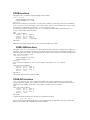
ANDGATE1
Let’s do another quick little machine and install both machines so you can see them
running concurrently.
MACHINE ANDGATE1 ON-MACHINE ANDGATE1 APPEND-STATE X
IN-STATE X CONDITION YELLED OFF PA7 ON? PB7 ON? AND CAUSES YELLED ON THEN-STATE
X TO-HAPPEN
X SET-STATE ( INSTALL ANDGATE1
MACHINE-CHAIN CHN1 REDTRIGGER ANDGATE1 END-MACHINE-CHAIN
EVERY 50000 CYCLES SCHEDULE-RUNS CHN1
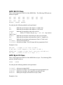
There you have it, another complete real time program in three lines of IsoMax™, and
one additional line to install it. A useful virtual machine is made here with one state and
one transition. This virtual machine acts (almost) like an AND gate made in hardware.
For example: http://www.philipslogic.com/products/hc/pdf/74hc08.pdf
Both PA7 and PB7 must be on, or high, to allow the yellow LED to remain on (most of
the time). So by attaching push buttons to PA7 and PB7 simulating micro switches this
little program could be used like an interlock system detecting “cover closed”.
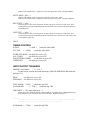
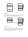
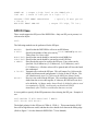
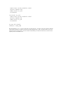
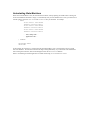
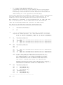
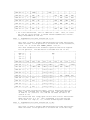
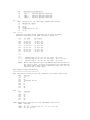
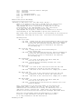
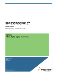
PROGRAM TEXT
MACHINE ANDGATE1
EQUIVALENT GRAPHIC
MAKE A MACHINE
ON-MACHINE ANDGATE1
APPEND-STATE X
IN-STATE
X
CONDITION
YELLED OFF
PA7 ON?
PB7 ON? AND
CAUSES
YELLED ON
THEN-STATE
X
TO-HAPPEN
ADD A STATE
YELLED OFF
PA7 ON?
PB7 ON? AND
YELLED ON
ADD A TRANSITION
X
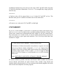
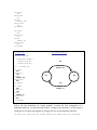
(Now it is worth mentioning, the example is a bit contrived. When you try to make a state
machine too simple, you wind up stretching things you shouldn’t. This example could
have acted exactly like an AND gate if two transitions were used, rather than just one.
Instead, a “trick” was used to turn the LED off every time in the condition, then turn it on
only when the condition was true. So a noise spike is generated a real “and” gate doesn’t
have. The trick made the machine simpler, it has half the transitions, but it is less
functional. Later we’ll revisit this machine in detail to improve it.)
Notice both machines share an input, but are using the opposite sense on that input.
ANDGATE1 looks for PA7 to be ON, or HIGH. The internal pull up will normally make
PA7 high, as long as it is programmed for a pull up and nothing external pulls it down.
Grounding PA7 enables REDTRIGGER’s condition, and inhibits ANDGATE1’s condition. Yet
the two machines coexist peacefully on the same processor, even sharing the same inputs
in different ways.
To see these machines running enter the new code, if you are still running REDTRIGGER,
reset (toggle the DTR line on the terminal, for instance, Alt-T twice in MaxTerm or cycle
power) and download the whole of both programs.
Initialize REDTRIGGER for action by turning REDLED OFF as before. Grounding PA7 now
causes the same result for REDTRIGGER, the red LED goes on, but the opposite effect for
the yellow LED, which goes off while PA7 is grounded. Releasing PA7 turns the yellow
LED back on, but the red LED remains on.
Again, initialize REDTRIGGER by turning REDLED OFF. Now ground PB7. This has no
effect on the red LED, but turns off the yellow LED while grounded. Grounding both
PA7 and PB7 at the same time also turns off the yellow LED, and turns on the red LED if
not yet set.
Notice how the tightly the two machines are intertwined. Perhaps you can imagine how
very simple machines with combinatory logic and sharing inputs and feeding back
outputs can quickly start showing some complex behaviors. Let’s add some more
complexity with another machine sharing the PA7 input.
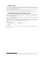
BOUNCELESS
We have another quick example of a little more complex machine, one with one state and
two transitions.
MACHINE BOUNCELESS ON-MACHINE BOUNCELESS APPEND-STATE Y
IN-STATE Y CONDITION PA7 OFF? CAUSES GRNLED OFF THEN-STATE Y TO-HAPPEN
IN-STATE Y CONDITION PB6 OFF? CAUSES GRNLED ON THEN-STATE Y TO-HAPPEN
Y SET-STATE ( INSTALL BOUNCELESS
MACHINE-CHAIN 3EASY
REDTRIGGER
ANDGATE
BOUNCELESS
END-MACHINE-CHAIN
EVERY 50000 CYCLES SCHEDULE-RUNS 3EASY
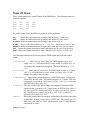
There you have yet another complete design, initialization and installation of a virtual
machine in four lines of IsoMax™ code.
Another name for the machine in this program is “a bounceless switch”.
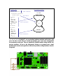
Bounceless switches filter out any noise on their input buttons, and give crisp, one-edge
output signals. They do this by toggling state when an input first becomes active, and
remaining in that state. If you are familiar with hardware, you might recognize the two
gates feed back on each other as a very elementary flip-flop. The flip-flop is a bistable
on/off circuit is the basis for a memory cell. The bounceless switch flips when one input
is grounded, and will not flip back until the other input is grounded.
By attaching push buttons to PA7 and PB6 the green LED can be toggled from on to off
with the press of the PA7 button, or off to on with the press of the PB6. The PA7 button
acts as a reset switch, and the PB6 acts as a set switch.
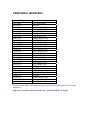
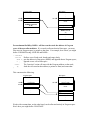
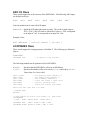
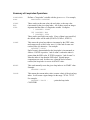
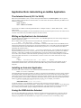
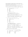
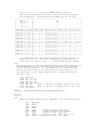
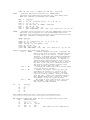
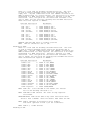
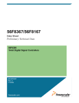
PROGRAM TEXT
MACHINE BOUNCELESS
EQUIVALENT GRAPHIC
MAKE A MACHINE
ON-MACHINE BOUNCELESS
APPEND-STATE Y
IN-STATE
Y
CONDITION
PA7 OFF?
CAUSES
GRNLED OFF
THEN-STATE
Y
TO-HAPPEN
IN-STATE
Y
CONDITION
PB6 OFF?
CAUSES
GRNLED ON
THEN-STATE
Y
TO-HAPPEN
PA7 OFF?
ADD A STATE
GRNLED OFF
ADD A TRANSITION
Y
PB6 OFF?
GRNLED ON
ADD A TRANSITION
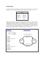
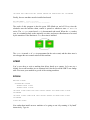
You can see here, in IsoMax™, you can simulate hardware machines and circuits, with
just a few lines of code. Here we created one machine, gave it one state, and appended
two transitions to that state. Then we installed the finished machine along with the two
previous machines. All run in the background, freeing us to program more virtual
machines that can also run in parallel, or interactively monitor existing machines from the
foreground.
Notice all three virtual hardware circuits are installed at the same time, they operate
virtually in parallel, and the ServoPod-USB™ is still not visibly taxed by having these
machines run in parallel. Further, all three machines share one input, so their behavior is
strongly linked.
SYNTAX AND FORMATTING
Let’s talk a second about pretty printing, or pretty formatting. To go a bit into syntax
again, you’ll need to remember the following. Everything in IsoMax™ is a word or a
number. Words and numbers are separated spaces (or returns).
Some words have a little syntax of their own. The most common cases for such words are
those that require a name to follow them. When you add a new name, you can use any
combinations of characters or letters except (obviously) spaces and backspaces, and
carriage returns. So, when it comes to pretty formatting, you can put as much on one line
as will fit (up to 80 characters). Or you can put as little on one line as you wish, as long
as you keep your words whole. However, some words will require a name to follow
them, so those names will have to be on the same line.
In the examples you will see white space (blanks) used to add some formatting to the
source text. MACHINE starts at the left, and is followed by the name of the new machine
being added to the language. ON-MACHNE is indented right by two spaces. APPEND-STATE
X is indented two additional spaces. This is the suggested, but not mandatory, offset to
achieve pretty formatting. Use two spaces to indent for levels. The transitions are
similarly laid out, where the required words are positioned at the left, and the user
programming is stepped in two spaces.
MULTIPLE STATES/MULTIPLE TRANSITIONS
Before we leave the previous “Three Machines”, let’s review the AND machine again,
since it had a little trick in it to keep it simple, just one state and one transition. The trick
does simplify things, but goes too far, and causes a glitch in the output. To make an AND
gate which is just like the hardware AND we need at least two transitions. The previous
example, BOUNCELESS was the first state machine with more than one transition. We’ll
follow this precedent and redo ANDGATE2 with two transitions.
ANDGATE2
MACHINE ANDGATE2
ON-MACHINE ANDGATE2
APPEND-STATE X
IN-STATE
X
CONDITION
PA7 ON?
PB7 ON? AND
CAUSES
YELLED ON
THEN-STATE
X
TO-HAPPEN
IN-STATE
X
CONDITION
PA7 OFF?
PB7 OFF? OR
CAUSES
YELLED OFF
THEN-STATE
X
TO-HAPPEN
X SET-STATE ( INSTALL ANDGATE2
EVERY 50000 CYCLES SCHEDULE-RUNS ANDGATE2
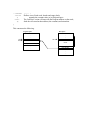
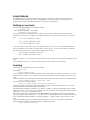
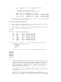
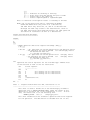
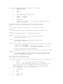
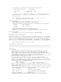
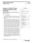
EQUIVALENT GRAPHIC
PROGRAM TEXT
MACHINE ANDGATE2
ON-MACHINE ANDGATE2
APPEND-STATE X
IN-STATE
X
CONDITION
PA7 ON?
PB7 ON? AND
CAUSES
YELLED ON
THEN-STATE
X
TO-HAPPEN
IN-STATE
X
CONDITION
PA7 OFF?
PB7 OFF? OR
CAUSES
YELLED OFF
THEN-STATE
X
TO-HAPPEN
MAKE A MACHINE
PA7 ON? PB7 ON? AND
APPEND STATE
YELLED ON
ADD A TRANSITION
X
PA7 OFF? PB7 OFF? OR
ADD A TRANSITION
YELLED OFF
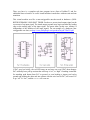
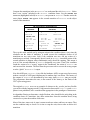
Compare the transitions in the two ANDGATE’s to understand the trick in ANDGATE1. Notice
there is an “action” included in the ANDGATE1 condition clause. See the YELLED OFF
statement (highlighted in bold) in ANDGATE1, not present in ANDGATE2? Further notice the
same phrase YELLED OFF appears in the second transition of ANDGATE2 as the object
action of that transition.
TRANSITION COMPARISON
ANDGATE1
IN-STATE
X
CONDITION
YELLED OFF
PA7 ON?
PB7 ON? AND
CAUSES
YELLED ON
THEN-STATE
X
TO-HAPPEN
IN-STATE
X
CONDITION
ANDGATE2
IN-STATE
X
CONDITION
PA7 ON?
PB7 ON? AND
CAUSES
YELLED ON
THEN-STATE
X
TO-HAPPEN
PA7 OFF?
PB7 OFF? OR
CAUSES
YELLED OFF
THEN-STATE
X
TO-HAPPEN
The way this trick worked was by using an action in the condition clause, every time the
scheduler ran the chain of machines, it would execute the conditions clauses of all
transitions on any active state. Only if the condition was true, did any action of a
transition get executed. Consequently, the trick used in ANDGATE1 caused the action of the
second transition to happen when conditionals (only) should be running. This meant it
was as if the second transition of ANDGATE2 happened every time. Then if the condition
found the action to be a “wrong” output in the conditional, the action of ANDGATE1 ran
and corrected the situation. The brief time the processor took to correct the wrong output
was the “glitch” in ANDGATE1’s output.
Now this AND gate, ANDGATE2, is just like the hardware AND, except not as fast as most
modern versions of AND gates implemented in random logic on silicon. The latency of
the outputs of ANDGATE2 are determined by how many times ANDGATE2 runs per second.
The programmer determines the rate, so has control of the latency, to the limits of the
CPU’s processing power.
The original ANDGATE1 serves as an example of what not to do, yet also just how flexible
you can be with the language model. Using an action between the CONDITION and CAUSES
phrase is not prohibited, but is considered not appropriate in the paradigm of Isostructure.
An algorithm flowing to determine a single Boolean value should be the only thing in the
condition clause of a transition. Any other action there slows the machine down, being
executed every time the machine chain runs.
Most of the time, states wait. A state is meant to take no action, and have no output. They
run the condition only to check if it is time to stop the wait, time to take an action in a
transition.
The actions we have taken in these simple machines if very short. More complex
machines can have very complex actions, which should only be run when it is absolutely
necessary. Putting actions in the conditional lengthens the time it takes to operate waiting
machines, and steals time from other transitions.
Why was it necessary to have two transitions to do a proper AND gate? To find the
answer look at the output of an AND gate. There are two possible mutually exclusive
outputs, a “1” or a “0”. Once action cannot set an output high or low. One output can set
a bit high. It takes a different output to set a bit low. Hence, two separate outputs are
required.
ANDOUT
Couldn’t we just slip an action into the condition spot and do away with both transitions?
Couldn’t we just make a “thread” to do the work periodically? Yes, perhaps, but that
would break the paradigm. Let’s make a non-machine definition. The output of our
conditional is in fact a Boolean itself. Why not define:
: ANDOUT PA7 ON? PB7 ON? AND IF YELLED ON ELSE YELLED OFF THEN ;
Why not forget the entire “machine and state” stuff, and stick ANDOUT in the machine
chain instead? There are no backwards branches in this code. It has no Program Counter
Capture (PCC) Loops. It runs straight through to termination. It would work.
This, however, is another trick you should avoid. Again, why? This code does one of two
actions every time the scheduler runs. The actions take longer than the Boolean test and
transfer to another thread. The system will run slower, because the same outputs are
being generated time after time, whether they have changed or not. While the speed
penalty in this example is exceedingly small, it could be considerable for larger state
machines with more detailed actions.
A deeper reason exists that reveals a great truth about state machines. Notice we have
used a state machine to simulate a hardware gate. What the AND gate outputs next is
completely dependent on what the inputs are next. An AND gate has an output which has
no feedback. An AND gate has no memory. State machines can have memory. Their
future outputs depend on more than the inputs present. A state machine’s outputs can also
depend on the history of previous states. To appreciate this great difference between state
machines and simple gates, we must first look a bit further at some examples with
multiple states and multiple transitions.
ANDGATE3
We are going to do another AND gate version, ANDGATE3, to illustrate this point about
state machines having multiple states. This version will have two transitions and two
states. Up until now, our machines have had a single state. Machines with a single state in
general are not very versatile or interesting. You need to start thinking in terms of
machines with many states. This is a gentle introduction starting with a familiar problem.
Another change is in effect here. We have previously first written the code so as to make
the program small in terms of lines. We used this style to emphasize small program
length. From now on, we are going to pretty print it so it reads as easily as possible,
instead.
MACHINE ANDGATE3
ON-MACHINE ANDGATE3
APPEND-STATE X0
APPEND-STATE X1
IN-STATE
X0
CONDITION
PA7 ON? PB7 ON? AND
CAUSES
YELLED ON
PB0 ON
THEN-STATE
X1
TO-HAPPEN
IN-STATE
X1
CONDITION
PA7 OFF? PB7 OFF? OR
CAUSES
YELLED OFF
PB0 OFF
THEN-STATE
X0
TO-HAPPEN
X0 SET-STATE ( INSTALL ANDGATE3
EVERY 50000 CYCLES SCHEDULE-RUNS ANDGATE3
PROGRAM TEXT
MACHINE ANDGATE3
ON-MACHINE ANDGATE3
APPEND-STATE X0
APPEND-STATE X1
IN-STATE
X0
CONDITION
PA7 ON? PB7 ON? AND
CAUSES
YELLED ON
PB0 ON
THEN-STATE
X1
TO-HAPPEN
IN-STATE
X1
CONDITION
PA7 OFF? PB7 OFF? OR
CAUSES
YELLED OFF
PB0 OFF
THEN-STATE
X0
TO-HAPPEN
EQUIVALENT GRAPHIC
MAKE A MACHINE
PA7 ON? PB7 ON? AND
ADD STATES
YELLED ON
PB0 ON
X0
ADD A TRANSITION
X1
PA7 OFF? PB7 OFF? OR
YELLED OFF
PB0 OFF
ADD A TRANSITION
Notice how similar this version of an AND gate, ANDGATE3, is to the previous version,
ANDGATE2. The major difference is that there are two states instead of one. We also added
some “spice” to the action clauses, doing another output on PB0, to show how actions
can be more complicated.
INTER-MACHINE COMMUNICATIONS
Now imagine ANDGATE3 is not an end unto itself, but just a piece of a larger problem.
Now let’s say another machine needs to know if both PA7 and PB7 are both high? If we
had only one state, it would have to recalculate the AND phrase, or read back what
ANDGATE3 had written as outputs. Rereading written outputs is sometimes dangerous,
because there are hardware outputs which is cannot be read back. If we use different
states for each different output, the state information itself stores which state is active. All
an additional machine has to do to discover the status of PA7 and PB7 AND’ed together
is check the stored state information of ANDGATE3. To accomplish this, simply query the
state this way.
X0 IS-STATE?
A Boolean value will be returned that is TRUE if either PA7 and PB7 are low. This
Boolean can be part of a condition in another state. On the other hand:
X1 IS-STATE?
will return a TRUE value only if PA7 and PB7 are both high.
STATE MEMORY
So you see, a state machine’s current state is as much as an output as the outputs PB0 ON
and YELLOW LED ON are, less likely to have read back problems, and faster to check. The
current state contains more information than other outputs. It can also contain history.
The current state is so versatile, in fact, it can store all the pertinent history necessary to
make any decision on past inputs and transitions. This is the deep truth about state
machines we sought.
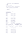
9-2 THE FINITE-STATE MODEL -- BASIC DEFINITION
The behavior of a finite-state machine is described as a sequence of events
that occur at discrete instants, designated t = 1, 2, 3, etc. Suppose that a
machine M has been receiving inputs signals and has been responding by
producing output signals. If now, at time t, we were to apply an input
signal x(t) to M, its response z(t) would depend on x(t), as well as the past
inputs to M.
From: SWITCHING AND FINITE AUTOMATA THEORY, KOHAVI
No similar solution is possible with short code threads. While variables can indeed be
used in threads, and threads can again reference those variable, using threads and
variables leads to deeply nested IF ELSE THEN structures and dreaded spaghetti code which
often invades and complicates real time programs.
BOUNCELESS+
To put the application of state history to the test, let’s revisit our previous version of the
machine BOUNCELESS. Refer back to the code for transitions we used in BOUNCELESS.
STATE Y
IN-STATE
IN-STATE
Y
Y
CONDITION
CONDITION
PA7 OFF?
PB6 OFF?
CAUSES
CAUSES
GRNLED OFF
GRNLED ON
THEN-STATE
THEN-STATE
Y
Y
TO-HAPPEN
TO-HAPPEN
This code worked fine, as long as PA7 and PB6 were pressed one at a time. The green
LED would go on and off without noise or bounces between states. Notice however, PA7
and PB6 being low at the same time is not excluded from the code. If both lines go low at
the same time, the output of our machine is not well determined. One state output will
take precedence over the other, but which it will be cannot be determined from just
looking at the program. Whichever transition gets first service will win.
PROGRAM TEXT
EQUIVALENT GRAPHIC
MACHINE BOUNCELESS+
ON-MACHINE BOUNCELESS+
APPEND-STATE WAITOFF
APPEND-STATE WAITON
IN-STATE
WAITOFF
CONDITION
PA7 OFF? PB7 ON? AND
CAUSES
GRNLED ON
THEN-STATE
WAITON
TO-HAPPEN
IN-STATE
WAITON
CONDITION
PB7 OFF? PA7 ON? AND
CAUSES
GRNLED OFF
THEN-STATE
WAITOFF
TO-HAPPEN
PA7 OFF? PB7 ON? AND
GRNLED ON
WAITOFF
WAITON
PB7 OFF? PA7 ON? AND
GRNLED OFF
Now consider how BOUNCELESS+ can be improved if the state machines history is
integrated into the problem. In order to have state history of any significance, however,
we must have multiple states. As we did with our ANDGATE3 let’s add one more state. The
new states are WAITON and WAITOFF and run our two transitions between the two states.
At first blush, the new machine looks more complicated, probably slower, but not
significantly different from the previous version. This is not true however. When the
scheduler calls a machine, only the active state and its transitions are considered. So in
the previous version each time Y was executed, two conditionals on two transitions were
tested (assuming no true condition). In this machine, two conditionals on only one
transition are tested. As a result this machine runs slightly faster.
Further, the new BOUNCELESS+ machine is better behaved. (In fact, it is better behaved
than the original hardware circuit shown!) It is truly bounceless, even if both switches are
pressed at once. The first input detected down either takes us to its state or inhibits the
release of its state. The other input can dance all it wants, as long as the one first down
remains down. Only when the original input is released can a new input cause a change
of state. In the rare case where both signals occur at once, it is the history, the existing
state, which determines the status of the machine.
STATE WAITOFF
IN-STATE
WAITOFF
CONDITION
PA7 OFF? PB7 ON? AND
CAUSES
GRNLED ON
THEN-STATE
WAITON
TO-HAPPEN
STATE WAITON
IN-STATE
WAITON
CONDITION
PB7 OFF? PA7 ON? AND
CAUSES
GRNLED OFF
THEN-STATE
WAITOFF
TO-HAPPEN
DELAYS
Let’s say we want to make a steady blinker out of the green LED. In a conventional
procedural language, like BASIC, C, FORTH, or Java, etc., you’d probably program a
loop blinking the LED on then off. Between each loop would be a delay of some kind,
perhaps a subroutine you call which also spins in a loop wasting time.
Assembler
LOOP1 LDX # 0
LOOP2 DEX
BNE LOOP2
LDAA #1
STAA PORTA
LDX # 0
LOOP3 DEX
BNE LOOP3
LDAA #N
STAA PORTA
BASIC
FOR I=1 TO N
GOSUB DELAY
C JAVA
While ( 1 )
{ delay(x);
FORTH
BEGIN
DELAY
LET PB=TRUE
out(1,portA1);
LED-ON
GOSUB DELAY
delay(x);
DELAY
Let PB=FALSE
out(0,portA1);
LED-OFF
JMP LOOP1
NEXT
}
AGAIN
Here’s where IsoMax™ will start to look different from any other language you’re likely
to have ever seen before. The idea behind Virtually Parallel Machine Architecture is
constructing virtual machines, each a little “state machine” in its own right. But this
IsoStructure requires a limitation on the machine, themselves. In IsoMax™, there are no
program loops, there are no backwards branches, there are no calls to time wasting delays
allowed. Instead we design machines with states. If we want a loop, we can make a state,
then write a transition from that state that returns to that state, and accomplish roughly the
same thing. Also in IsoMax™, there are no delay loops.
The whole point of having a state is to allow “being in the state” to be “the delay”.
Breaking this restriction will break the functionality of IsoStructure, and the parallel
machines will stop running in parallel. If you’ve ever programmed in any other language,
your hardest habit to break will be to get away from the idea of looping in your program,
and using the states and transitions to do the equivalent of looping for you.
A valid condition to leave a state might be a count down of passes through the state until
a 0 count reached. Given the periodicity of the scheduler calling the machine chain, and
the initial value in the counter, this would make a delay that didn’t “wait” in the
conventional sense of backwards branching.
BLINKGRN
Now for an example of a delay using the count down to zero, we make a machine
BLINKGRN. Reset your ServoPod-USB™ so it is clean and clear of any programs, and
then begin.
MACHINE BLINKGRN
ON-MACHINE BLINKGRN
APPEND-STATE BG1
APPEND-STATE BG2
The action taken when we leave the state will be to turn the LED off and reinitialize the
counter. The other half of the problem in the other state we go to is just the reversed. We
delay for a count, then turn the LED back on.
Since we’re going to count, we need two variables to work with. One contains the count,
the other the initial value we count down from. Let’s add a place for those variables now,
and initialize them
: -LOOPVAR <BUILDS HERE P, 1- DUP , , DOES>
P@ DUP @ 0= IF DUP 1 + @ SWAP ! TRUE ELSE 1-! FALSE THEN ;
100 -LOOPVAR CNT
IN-STATE
BG1
CONDITION
CNT
CAUSES
GRNLED OFF
THEN-STATE
BG2
TO-HAPPEN
IN-STATE
BG2
CONDITION
CNT
CAUSES
GRNLED ON
THEN-STATE
BG1
TO-HAPPEN
PROGRAM TEXT
EQUIVALENT GRAPHIC
MACHINE BLINKGRN
ON-MACHINE BLINKGRN
APPEND-STATE BG1
APPEND-STATE BG2
CNT
100 0 LOOPVAR CNT
GRNLED OFF
IN-STATE
BG1
CONDITION
CNT
CAUSES
GRNLED OFF
THEN-STATE
BG2
TO-HAPPEN
IN-STATE
BG2
CONDITION
CNT
CAUSES
GRNLED ON
THEN-STATE
BG1
BG1
BG2
CNT
GRNLED ON
TO-HAPPEN
Above, the two transitions are “pretty printed” to make the four components of a
transition stand out. As discussed previously, as long as the structure is in this order it
could just as well been run together on a single line (or so) per transition, like this
IN-STATE BG1 CONDITION CNT CAUSES GRNLED OFF THEN-STATE BG2 TO-HAPPEN
IN-STATE BG2 CONDITION CNT CAUSES GRNLED ON THEN-STATE BG1 TO-HAPPEN
Finally, the new machine must be installed and tested
BG1 SET-STATE ( INSTALL BLINKGRN
EVERY 50000 CYCLES SCHEDULE-RUNS BLINKGRN
The result of this program is that the green LED blinks on and off. Every time the
scheduler runs the machine chain, control is passed to whichever state BG1 or BG2 is
active. The -LOOPVAR created word CNT is decremented and tested. When the CNT reaches
zero, it is reinitialize back to the originally set value, and passes a Boolean on to be tested
by the transition. If the Boolean is TRUE, the action is initiated.
The GRNLED is turned ON of OFF (as programmed in the active state) and the other state is
set to happen the next control returns to this machine.
SPEED
You’ve seen how to write a machine that delays based on a counter. Let’s now try a
slightly less useful machine just to illustrate how fast the ServoPod-USB™ can change
state. First reset your machine to get rid of the existing machines.
ZIPGRN
MACHINE ZIPGRN
ON-MACHINE ZIPGRN
APPEND-STATE ZIPON
APPEND-STATE ZIPOFF
IN-STATE ZIPON CONDITION TRUE CAUSES GRNLED OFF THEN-STATE ZIPOFF
TO-HAPPEN
IN-STATE ZIPOFF CONDITION TRUE CAUSES GRNLED ON THEN-STATE ZIPON
TO-HAPPEN
ZIPON SET-STATE
Now rather than install our new machine we’re going to test it by running it “by hand”
interactively. Type in:
ZPON SET-STATE
ZIPGRN
ZIPGRN should cause a change in the green LED. The machine runs as quickly as it can to
termination, through one state transition, and stops. Run it again. Type:
ZIPGRN
Once again, the green LED should change. This time the machine starts in the state with
the LED off. The always TRUE condition makes the transition’s action happen and the
next state is set to again, back to the original state. As many times as you run it, the
machine will change the green LED back and forth.
Now with the machine program and tested, we’re ready to install the machine into the
machine chain. The phrase to install a machine is :
EVERY n CYCLES SCHEDULE-RUNS word
So for our single machine we’d say:
ZIPON SET-STATE
EVERY 5000 CYCLES SCHEDULE-RUNS ZIPGRN
Now if you look at your green LED, you’ll see it is slightly dimmed.
That’s because it is being turned off half the time, and is on half the time. But it is
happening so fast you can’t even see it.
REDYEL
Let’s do another of the same kind. This time lets do the red and yellow LED, and have
them toggle, only one on at a time. Here we go:
MACHINE REDYEL
ON-MACHINE REDYEL
APPEND-STATE REDON
APPEND-STATE YELON
IN-STATE REDON CONDITION TRUE CAUSES REDLED OFF YELLED ON THEN-STATE
YELON TO-HAPPEN
IN-STATE YELON CONDITION TRUE CAUSES REDLED ON YELLED OFF THEN-STATE
REDON TO-HAPPEN
Notice we have more things happening in the action this time. One LED is turned on and
one off in the action. You can have multiple instructions in an action.
Test it. Type:
REDON SET-STATE
REDYEL
REDYEL
REDYEL
REDYEL
See the red and yellow LED’s trade back and forth from on to off and vice versa.
All this time, the ZIPGRN machine has been running in the background, because it is in
the installed machine chain. Let’s replace the installed machine chain with another. So
we define a new machine chain with both our virtual machines in it, and install it.
MACHINE-CHAIN CHN2
ZIPGRN
REDYEL
END-MACHINE-CHAIN
REDON SET-STATE
EVERY 5000 CYCLES SCHEDULE-RUNS CHN2
With the new machine chain installed, all three LED’s look slightly dimmed.
Again, they are being turned on and off a thousand times a second. But to your eye, you
can’t see the individual transitions. Both our virtual machines are running in virtual
parallel, and we still don’t see any slow down in the interactive nature of the ServoPodUSB™.
So what was the point of making these two machines? Well, these two machines are
running faster than the previous ones. The previous ones were installed with 50,000
cycles between runs. That gave a scan-loop repetition of 100 times a second. Fine for
many mechanical issues, on the edge of being slow for electronic interfaces. These last
examples were installed with 5,000 cycles between runs. The scan-loop repetition was
1000 times a second. Fine for many electronic interfaces, that is fast enough. Now let’s
change the timing value. Redo the installation with the SCHEDULE-RUNS command.
The scan-loop repetition is 10,000 times a second.
EVERY 500 CYCLES SCHEDULE-RUNS CHN2
Let’s see if we can press our luck.
EVERY 100 CYCLES SCHEDULE-RUNS CHN2
Even running two machines 50,000 times a second in high-level language, there is still
time left over to run the foreground routine. This means, two separate tasks are being
started and running a series of high-level instructions 50,000 times a second. This shows
the ServoPod-USB™ is running more than four hundred thousand high-level instructions
per second. The ServoPod-USB™ performance is unparalleled in any small computer
available today.
TRINARIES
With the state machine structures already given, and a simple input and output words
many useful machines can be built. Almost all binary digital control applications can be
written with the trinary operators.
As an example, let’s consider a digital thermostat. The thermostat works on a digital
input with a temperature sensor that indicates the current temperature is either above or
below the current set point. The old style thermostats had a coil made of two dissimilar
metals, so as the temperature rose, the outside metal expanded more rapidly than the
interior one, causing a mercury capsule to tip over. The mercury moving to one end of the
capsule or the other made or broke the circuit. The additional weight of mercury caused a
slight feedback widening the set point. Most heater systems are digital in nature as well.
They are either on or off. They have no proportional range of heating settings, only
heating and not heating. So in the case of a thermostat, everything necessary can be
programmed with the machine format already known, and a digital input for temperature
and a digital output for the heater, which can be programmed with trinaries.
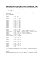
Input trinary operators need three parameters to operate. Using the trinary operation
mode of testing bits and masking unwanted bits out would be convenient. This mode
requires: 1) a mask telling which bits in to be checked for high or low settings, 2) a mask
telling which of the 1 possible bits are to be considered, and 3) the address of the I/O port
you are using. The keywords which separate the parameters are, in order: 1) SET-MASK,
2) CLR-MASK and 3) AT-ADDRESS. Finally, the keyword FOR-INPUT finishes the
defining process, identifying the trinary operator in effect.
DEFINE <name> TEST-MASK <mask> DATA-MASK <mask> AT-ADDRESS <address> FOR-INPUT
Putting the keywords and parameters together produces the following lines of IsoMax™
code. Before entering hexadecimal numbers, the keyword HEX invokes the use of the
hexadecimal number system. This remains in effect until it is change by a later command.
The numbering system can be returned to decimal using the keyword DECIMAL:
HEX
DEFINE TOO-COLD? TEST-MASK 01 DATA-MASK 01 AT-ADDRESS 0FB1 FOR-INPUT
DEFINE TOO-HOT? TEST-MASK 01 DATA-MASK 00 AT-ADDRESS 0FB1 FOR-INPUT
DECIMAL
Output trinary operators also need three parameters. In this instance, using the trinary
operation mode of setting and clearing bits would be convenient. This mode requires: 1) a
mask telling which bits in the output port are to be set, 2) a mask telling which bits in the
output port are to be cleared, and 3) the address of the I/O port. The keywords which
proceed the parameters are, in order: 1) SET-MASK, 2) CLR-MASK and 3) ATADDRESS. Finally, the keyword FOR-OUTPUT finishes the defining process, identifying
which trinary operator is in effect.
DEFINE <name> AND-MASK <mask> XOR-MASK <mask> AT-ADDRESS <address> FOR-OUTPUT
DEFINE <name> CLR-MASK <mask> SET-MASK <mask> AT-ADDRESS <address> FOR-OUTPUT
A single output port line is needed to turn the heater on and off. The act of turning the
heater on is unique and different from turning the heater off, however. Two actions need
to be defined, therefore, even though only one I/O line is involved. PA1 was selected for
the heater control signal.
When PA1 is high, or set, the heater is turned on. To make PA1 high, requires PA1 to be
set, without changing any other bit of the port. Therefore, a set mask of 02 indicates the
next to least significant bit in the port, corresponding to PA1, is to be set. All other bits
are to be left alone without being set. A clear mask of 00 indicates no other bits of the
port are to be cleared.
When PA1 is low, or clear, the heater is turned off. To make PA1 low, requires PA1 to be
cleared, without changing any other bit of the port. Therefore, a set mask of 00 indicates
no other bits of the port are to be set. A clear mask of 02 indicates the next to least
significant bit in the port, corresponding to PA1, is to be cleared. All other bits are to be
left alone without being cleared.
Putting the keywords and parameters together produces the following lines of IsoMax™
code:
HEX
DEFINE HEATER-ON SET-MASK 02 CLR-MASK 00 AT-ADDRESS 0FB0 FOR-OUTPUT
DEFINE HEATER-OFF SET-MASK 00 CLR-MASK 02 AT-ADDRESS 0FB0 FOR-OUTPUT
DECIMAL
Only a handful of system words need to be covered to allow programming at a system
level, now.
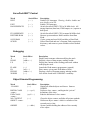
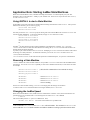
FLASH AND AUTOSTARTING
Here’s everything you need to copy an application to Flash and to autostart it. Here,
briefly, are the steps:
1. You should start with a clean Servopod, by doing SCRUB. This will erase
the Program Flash and remove any previous autostart patterns.
2. In the program file, each Forth word should be followed by EEWORD. This
applies to colon definitions, CODE and CODE-SUB words, constants,
variables, "defined" words (those created with <BUILDS..DOES>), and objects
(those created with OBJECT).
3. If IMMEDIATE is used, it must come *before* EEWORD (i.e., you must do
IMMEDIATE EEWORD and *not* EEWORD IMMEDIATE).
4. For IsoMax code the following rules apply:
a. MACHINE <name> must be followed by EEWORD.
b. APPEND-STATE <name> must be followed by EEWORD.
c. IN-STATE ... TO-HAPPEN (or THIS-TIME or NEXT-TIME) must be followed by
IN-EE.
d. MACHINE-CHAIN ... END-MACHINE-CHAIN must be followed by EEWORD.
e. ON-MACHINE <name> is *not* followed by any EE command.
[Note that we can make EEWORD and IN-EE automatic, if you want all state
machines to be built in Flash and never in RAM.]
5. When the application is complete, you must use SAVE-RAM to preserve the
state machine variables in Data Flash. (This does *not* save kernel
variables.)
6. Finally you can set the autostart vector in Program Flash.
AUTOSTART <wordname>
E.g., AUTOSTART MAIN
<address> AUTOSTART <wordname> (from V0.3 to V0.62 )
E.g., HEX 3C00 AUTOSTART MAIN
The board should now reset into the application program.
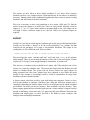
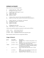
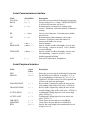
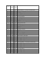
ISOMAX GLOSSARY
Stack comments use the following notation:
n
u
+n
w
16b
addr
a signed 16-bit value, -32768..+32767.
an unsigned 16-bit value, 0..65535.
a signed, positive 16-bit value, 0..+32767.
a generic16-bit value.
a generic 16-bit value.
an address (16 bits).
c
8b
a character. (Note: stored as 16 bits on the ServoPod-USB™™)
a generic 8-bit value. (Note: stored as 16 bits on the ServoPod-USB™™)
d
ud
wd
32b
a signed 32-bit value, -2,147,483,648..+2,147,483,647.
an unsigned 32-bit value, 0..4,294,967,295.
a generic 32-bit value.
a generic 32-bit value.
r
flag
a floating-point (real) value.
a logical flag, zero = false, -1 (all ones) = true.
Values on the stack before and after execution of a word are given as follows:
( before --- after )
normal integer data stack
(F: before --- after ) floating-point data stack
(C: before --- after ) compile-time behavior of the integer data stack.
Stack comments in italics also refer to compile-time behavior.
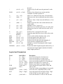
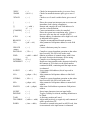
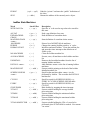
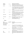
Integer Arithmetic
Word
*
*/
*/MOD
+
+!
-
Stack Effect
( w1 w2 --- w3 )
Description
Multiplies w2 by w1 and leaves the product w3 on
the stack.
( n1 n2 n3 --- n4 )
Multiplies n2 by n1 and divides the product by n3.
The quotient, n4 is placed on the stack.
( n1 n2 n3 -- n4 n5 ) n1 is multiplied by n2 producing a product which is
divided by n3. The remainder, n4 and the quotient,
n5 are then placed on the stack.
(w1 w2 --- w3 )
Adds w2 and w1 then leaves the sum, w3 on the
stack.
( w1 addr --- )
Adds w1 to the value at addr then stores the sum at
addr replacing its previous value.
( w1 w2 --- w3 )
Subtracts w2 from w1 and leaves the result, w3 on
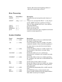
/
( n1 n2 --- n3 )
/MOD
( n1 n2 --- n3 n4 )
1+
1+!
( w1 --- w2 )
( addr --- )
1-
( w1 --- w2 )
1-!
( addr --- )
2*
2+
2-
( w1 --- w2 )
( w1 --- w2 )
( w1 --- w2 )
2/
><
ABS
MAX
MIN
MOD
NEGATE
UM*
( n1 --- n2 )
( 8b1/8b2 --8b2/8b1 )
( n --- u )
( n1 n2 --- n3 )
( n1 n2 --- n3 )
( n1 n2 --- n3 )
( n1 --- n2 )
( u1 u2 ---ud )
UM/MOD
( ud u1 --- u2 u3 )
the stack.
Divides n1 by n2 and leaves the quotient n3 on the
stack.
Divides n1 by n2 then leaves on the stack the
remainder n3 and the quotient n4.
Adds 1 to w1 then leaves the sum, w2 on the stack.
Adds one to the value at addr and stores the result at
addr.
Subtract 1 from w1 then leaves the difference, w2 on
the stack.
Subtracts one from the value at addr and stores the
result at addr.
Multiplies w1 by 2 to give w2.
Adds two to w1 and leaves the sum, w2 on the stack.
Subtracts two from w1 and leaves the result, w2 on
the stack.
Divides n1 by 2, giving n2 as the result.
Swaps the upper and lower bytes of the value on the
stack.
Leaves on the stack the absolute value, u of n.
Leaves the greater of n1 and n2 as n3.
Leaves the lesser of n1 and n2 as n3.
Divides n1 by n2 and leaves the remainder n3.
Leaves the two's complement n2 of n1.
Multiplies u1 and u2 returning the double length
product ud.
Divides the double length unsigned number ud by u1
and returns the single length remainder u2 and the
single length quotient u3.
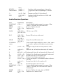
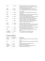
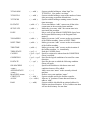
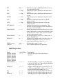
Logical and Comparison
Word
0<
0=
0>
<
=
>
AND
Stack Effect
( n --- flag )
( w --- flag )
( n --- flag )
( n1 n2 --- flag )
( w1 w2 --- flag )
( n1 n2 --- flag )
( 16b1 16b2 --16b3 )
CLEAR-BITS
INVERT
NOT
( 16b1 --- 16b2 )
( flag1 --- flag2 )
OR
( 16b1 16b2 ---
Description
Leaves a true flag if n is less than zero.
Leaves a true flag if w is equal to zero.
Leaves a true flag if n is greater than zero.
Leaves a true flag on stack if n1 is less than n2.
Returns a true flag if w1 is equal to w2.
Returns a true flag if n1 is greater than n2.
Leaves the bitwise logical AND of 16b1 and
16b2 as 16b3.
Clears bits at addr corresponding to 1s in mask b.
Leaves the one's complement 16b2 of 16b1.
Leaves the logical inverse flag2 of flag1. flag2
is false if flag1 was true, and vice versa.
Leaves the inclusive-or 16b3 of 16b1 an 16b2.
SET-BITS
TOGGLE-BITS
U<
XOR
16b3 )
( b addr --- )
( b addr --- )
Sets bits at addr corresponding to 1s in mask b.
Toggles bits at addr corresponding to 1s in mask
b.
Returns a true flag if u1 is less then u2.
Performs a bit-by-bit exclusive or of 16b1 with
16b2 to give 16b3.
( u1 u2 ---flag )
( 16b1 16b2 --16b3 )
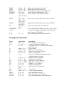
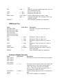
Double-Precision Operations
Word
2CONSTANT
<name>
2DROP
2DUP
2OVER
2ROT
2SWAP
2VARIABLE
<name>
D*
D+
DD/
D0=
D2/
D<
D=
DABS
DCONSTANT
<name>
DDROP
DDUP
Stack Effect
( 32b --- )
( 32b --- )
( 32b --- 32b
32b )
( 32b1 32b2 --32b1 32b2 32b3
)
( 32b1 32b2
32b3 --- 32b2
32b3 32b1 )
( 32b1 32b2 --32b2 32b1 )
( --- )
( d1 d2 --- d3 )
( wd1 wd2 --wd3 )
( wd1 wd2 --- wd3
( d1 d2 --- d3 )
( wd --- flag )
( d1 --- d2 )
( d1 d2 --- flag )
( wd1 wd2 --flag )
( d --- ud )
( 32b --- )
( 32b --- )
( 32b --- 32b
32b )
Description
Creates a double length constant for a <name>. When
<name> is executed, 32b is left on the stack.
Removes 32b from the stack.
Duplicates 32b.
32b3 is a copy of 32b1
Rotates 32b1 to the top of the stack.
Swaps 32b1 and 32b2 on the stack.
Creates double-length variable for <name>. when <name>
is executed, its parameter field address is placed on the
stack.
Multiplies d1 by d2 and leaves the product d3 on the
stack.
Adds wd1 and wd2 and leaves the result, wd3 on stack.
Subtracts wd2 from wd1 and returns the dif- ference wd3.
Divides d1 by d2 and leaves the quotient d3 on the stack.
Returns a true flag if wd is equal to zero.
Divides d1 by 2 and gives quotient d2.
Leaves a true flag if d1 is less than d2; otherwise leaves a
false flag.
Returns a true flag if wd1 is equal to wd2.
Returns the absolute value of d as ud.
Creates a double length constant for a <name>. When
<name> is executed, 32b is left on the stack. Same as
2CONSTANT.
Removes 32b from the stack. Same as 2DROP.
Duplicates 32b. Same as 2DUP.
DMAX
DMIN
DMOD
DNEGATE
DOVER
DROT
DSWAP
DU<
DVARIABLE
<name>
S->D
( d1 d2 --- d3 )
( d1 d2 --- d3 )
( d1 d2 --- d3 )
( d1 --- d2 )
( 32b1 32b2 --32b1 32b2 32b3
)
( 32b1 32b2
32b3 --- 32b2
32b3 32b1 )
( 32b1 32b2 --32b2 32b1 )
( ud1 ud2 --flag )
( --- )
( n --- d )
Returns d3 as the greater of d1 or d2.
Returns d3 as the lesser of d1 or d2.
Divides d1 by d2 and leaves the remainder d3.
Leaves the two's complement d2 of d1.
32b3 is a copy of 32b1. Same as 2OVER.
Rotates 32b1 to the top of the stack. Same as 2ROT.
Swaps 32b1 and 32b2 on the stack. Same as 2SWAP.
Returns a true flag if ud1 is less than ud2.
Creates double-length variable for <name>. when <name>
is executed, its parameter field address is placed on the
stack. Same as 2VARIABLE.
Sign extend single number to double number.
Floating-point Operations
Word
2**X
D>F
e
Stack Effect
(F: r1 -- r2)
(d -- ) (F: -- r)
(F: -- r1)
F!
F*
F**
F+
F,
(addr -- ) (F:r -- )
(F:r1 r2 -- r3)
(F:r1 r2 -- r3)
(F:r1 r2 -- r3)
(F:r -- )
FF/
F0<
F0=
F2*
F2/
F<
(F:r1 r2 -- r3)
(F:r1 r2 -- r3)
(F:r -- ) ( -- flag)
(F:r -- ) ( -- flag)
(F:r1 -- r2)
(F:r1 -- r2)
(F:r1 r2 -- )( -flag)
(F:r -- )( -- d)
(addr -- )(F: -- r)
(F:r1 -- r2)
(F:r1 -- r2)
(F:r1 -- r2)
F>D
F@
FABS
FALOG
FATAN
Description
Raise 2 to the r1 power giving r2.
R is the floating-point equivalent of d.
Put natural value e (=2.718282) on the floatingpoint stack as r1.
Store r at addr.
Multiply r1 by r2 giving r3.
Raise r1 to the r2 power giving r3.
Add r1 to r2, giving r3.
Store r as a floating-point number in the next
available dictionary location.
Subtract r2 from r1, giving r3.
Divide r1 by r2, giving r3.
flag is true if r is less than zero.
flag is true if r is equal to zero.
Multiply r1 by 2 giving r2.
Divide r1 by 2 giving r2.
flag is true if r1 is less than r2.
Convert r to d.
r is the value stored at addr.
R2 is the absolute value of r1.
Raise 10 to the power r1, giving r2.
R2 is the principal radian whose tangent is r1.
FATAN2
FCONSTANT
<name>
FCOS
FDEPTH
(F:r1 r2 -- r3 )
(F:r -- )
R3 is the radian angle whose tangent is r1/r2.
Define a constant <name> with value r.
(F:r1 -- r2)
( -- +n)
FDROP
FDUP
FEXP
FLN
FLOAT+
FLOATS
(F:r-- )
(F:r -- r r)
(F:r1 -- r2)
(F:r1 -- r2)
(addr1 -- addr2)
(n1 -- n2)
FLOG
FLOOR
(F:r1 -- r2 )
(F:r1 -- r2)
FMAX
FMIN
FNEGATE
FNIP
(F:r1 r2 -- r3)
(F:r1 r2 -- r3)
(F:r1 -- r2)
(F:r1 r2 -- r2)
FOVER
(F:r1 r2 -- r1 r2
r1)
(F:r1 -- r2)
r2 is the cosine of the radian angle r1.
+n is the number of values contained on separate
floating point stack.
Remove r from the floating-point stack.
Duplicate r.
Raise e to the power r1, giving r2.
R2 is the natural logarithm of r1.
Add the size of a floating-point value to addr1.
n2 is the size, in bytes, of n1 floating-point
numbers.
R2 is the base 10 logarithm of r1.
Round r1 using the "round to negative infinity"
rule, giving r2.
r3 is the maximum of r1 and r2.
r3 is the minimum of r2 and r3.
r2 is the negation of r1.
Remove second number down from floating-point
stack.
Place a copy of r1 on top of the floating-point
stack.
Round r1 using the ";round to even"; rule, giving
r2.
R2 is the sine of the radian angle r1.
R2 is the square root of r1.
Exchange the top two floating-point stack items.
R2 is the tangent of the radian angle r1.
Create a floating-point variable <name>. Reserve
data memory in the dictionary sufficient to hold a
floating-point value.
R2 is the base 2 logarithm of r1.
Evaluate odd-polynomial giving r1.
Put the numerical value of pi on the floating- point
stack as r1.
Evaluate polynomial giving r1.
R is the floating-point equivalent of n.
Store the floating point number r as a 32 bit IEEE
single precision number at addr.
Fetch the 32-bit IEEE single precision number
stored at addr to the floating-point stack as r in the
internal representation.
FROUND
FSIN
FSQRT
FSWAP
FTAN
FVARIABLE
<name>
(F:r1 -- r2 )
(F:r1 -- r2)
(F:r1 r2 -- r2 r1)
(F:r1 -- r2)
( -- )
LOG2
ODD-POLY
PI
(F:r1 -- r2)
(F: -- r1)(addr -- )
(F: -- r1)
POLY
S>F
SF!
(F: -- r1)(addr -- )
(n--)(F: -- r)
(addr -- )(F:r -- )
SF@
( addr -- )(F: -- r)
Stack Operations
Word
-ROLL
Stack Effect
( n --- )
>R
( 16b --- )
?DUP
( 16b --- 16b 16b ),
( 0 --- 0 )
( --- +n )
( 16b --- )
( 16b --- 16b 16b )
( 16b1 16b2 --16b1 16b2 16b3 )
( +n --- 16b )
( --- 16b )
DEPTH
DROP
DUP
OVER
PICK
R>
R@
ROLL
ROT
RP!
RP@
SP!
SP@
SWAP
Description
Removes the value on the top of stack and inserts it
into the nth place from the top of stack.
Removes 16b from user stack and place it onto
return stack.
Duplicates 16b if it is a non-zero.
Returns count +n of numbers on the data stack.
Removes 16b from the data stack.
Duplicates 16b.
16b3 is a copy of 16b1.
Copies the data stack's +nth item onto the top.
16b is removed from the return stack and placed
onto the data stack.
( --- 16b )
16b is a copy of the top of the return stack.
( +n --- )
Removes the stack's nth item and places it onto the
top of stack.
( 16b1 16b2 16b3 -- Rotates 16b1 to the top of the stack.
- 16b2 16b3 16b1 )
( -- )
Initializes the bottom of the return stack.
( -- addr)
addr is the address of the top of the return stack just
before RP@ was executed.
( -- )
Initializes the bottom of the parameter stack.
( --- addr )
addr is the address of the top of the parameter stack
just before SP@ was executed.
( 16b1 16b2 --Exchanges positions of the top two items of the
16b2 16b1 )
stack.
String Operations
Word
-TRAILING
Stack Effect
( addr +n1 --addr +n2 )
."
( --- )
.(
COUNT
( --- )
( addr1 --- addr2
+n )
( addr1 --- addr2
+n )
PCOUNT
Description
Counts +n1 characters starting at addr and subtracts
1 from the count when a blank is encountered.
Leaves on the stack the final string count, n2 and
addr.
Displays the characters following it up to the
delimiter " .
Displays string following .( delimited by ) .
Leaves the address, addr2 and the character count +n
of text beginning at addr1.
Leaves the address, addr2 and the character count +n
of text beginning at addr1 in Program memory.
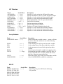
Terminal I/O
Word
?KEY
?TERMINAL
CR
EMIT
Stack Effect
( --- flag )
( --- flag )
( --- )
( 16b --- )
EXPECT
( addr +n --- )
KEY
( --- 16b)
PTYPE
( addr +n ---)
SPACE
SPACES
( --- )
( +n --- )
TYPE
( addr +n ---)
Description
True if any key is depressed.
True if any key is depressed. Same as ?KEY.
Generates a carriage return and line feed.
Displays the ASCII equivalent of 16b onto the
screen.
Stores up to +n characters into memory beginning at
addr.
Pauses to wait for a key to be pressed and then
places the ASCII value of the key (n) on the stack.
Displays a string of +n characters from Program
memory, starting with the character at addr.
Sends a space (blank) to the current output device.
Sends +n spaces (blanks) to the current output
device.
Displays a string of +n characters starting with the
character at addr.
Numeric Output
Word
#
Stack Effect
( +d1 --- +d2 )
#>
( 32b --- addr +n )
#S
(E.)
( +d --- 0 0 )
(F:r -- )( -- addr +n)
(F.)
(F:r -- )( -- addr +n)
.
.R
( n --- )
( n +n --- )
<#
( --- )
Description
+d1 is divided by BASE and the quotient is placed
onto the stack. The remainder is converted to an
ASCII character and appended to the output string
toward lower memory addresses.
Terminates formatted (or pictured) output string
(ready for TYPE ).
Converts all digits of an entire number into string.
Convert the top number on the floating-point stack
to its character string representation using the
scientific notation. Addr is the address of the
location where the character string representation of
r is stored, and +n is the number of bytes.
Convert the top number on the floating-point stack
to its character string representation using the fixedpoint notation. Addr is the address of the location
where the character string representation of r is
stored, and +n is the number of bytes.
Removes n from the top of stack and displays it.
Displays the value n right justified in a field +n
characters wide according to the value of BASE.
Starts a formatted (pictured) numeric output.
?
BASE
( addr --- )
( --- addr )
D.
D.R
( d --- )
( d +n --- )
DECIMAL
E.
( --- )
( -- )(F:r -- )
F.
(F:r --)( -- )
F?
HEX
(addr -- )
( --- )
HOLD
( char --- )
PLACES
(n --- )
SIGN
( n --- )
U.
( u --- )
U.R
( u +n --- )
Terminated by #> .
Displays the contents of addr.
Leaves the address of the user variable containing
the numeric numeric conversion radix.
Displays the value of d.
Displays the value of d right justified in a field +n
characters wide.
Sets the input-output numeric conversion base to ten.
Convert the top number on the floating-point stack
to its character string representation using the
scientific notation.
Print the top number on the floating-point stack on
the screen using fixed-point notation.
Display the floating-point contents stored at addr.
Sets the numeric input-output conversion base to
sixteen.
Inserts character into a pictured numeric out- put
string.
Set the number of decimal places (digits to the right
of the radix point) displayed by E. and F.
Appends an ASCII "; - "; (minus sign) to the start of
a pictured numeric output string if n is negative.
Displays the unsigned value of u followed by a
space.
Displays the value of u right justified in a field +n
characters wide according to the value of BASE.
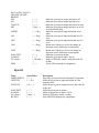
Numeric Input
Word
CONVERT
FNUMBER
NUMBER
Stack Effect
( +d1 addr1 --+d2 addr2 )
(+d1 addr1 -- +d2
addr2)
( addr --- d )
Description
Converts an input string into a number.
Converts an input string into a number.
Converts the counted string at addr to d according to
the value of BASE .
Memory Operations
Word
!
2!
2@
@
Stack Effect
( 16b addr --- )
( 32b addr --- )
( addr --- 32b )
( addr --- 16b )
Description
Stores 16b at addr.
Stores 32b at addr.
Returns 32b from addr.
Replaces addr with its 16b contents on top of the
@!
@@
( 16b addr --- )
( addr --- 16b )
BLANK
( addr u --- )
C!
C@
CMOVE
( c addr --- )
( addr --- c )
( addr1 addr2 u --- )
CMOVE>
D!
D@
EE!
EEC!
( addr1 addr2 u --- )
( 32b addr --- )
( addr --- 32b )
( 16b addr --- )
( 16b addr --- )
EEMOVE
( addr1 addr2 u --- )
EEERASE
( addr --- )
( addr u --- )
ERASE
EXCHANGE ( w1 addr --- w2 )
FILL
( addr u c --- )
P!
P@
( 16b addr --- )
( addr --- 16b )
PC!
( c addr --- )
PC@
( addr --- c )
PF!
PFERASE
PFMOVE
( 16b addr --- )
( addr --- )
( addr1 addr2 u --- )
TOGGLE
(addr b -- )
stack.
Stores 16 at address pointed to by addr.
Replaces addr with 16b, 16b is contents of address
pointed to by addr.
Sets u bytes of memory beginning at addr to the
ASCII code for space (decimal 32).
Stores the character c into addr.
Fetches the character c contents from addr.
Moves towards high memory the u bytes at addresses addr1 and addr2.
Moves u bytes beginning at addr1 to addr2.
Stores 32b at addr. Same as 2!
Returns 32b from addr. Same as 2@
Stores 16b into addr in EEPROM.
Stores the least significant byte of 16b into addr in
EEPROM.
Moves towards high memory the u bytes at
addresses addr1 and addr2. addr2 should be in
EEPROM.
Erase one page of Data Flash memory at addr.
Sets u bytes of memory to zero, beginning at addr.
Fetches contents w2 from addr, then stores w1 at
addr. (Exchanges w1 for w2 at addr.)
Fills u bytes, beginning at addr, with byte pattern
c.
Stores 16b into Program memory at at addr.
Fetches the 16b contents from Program memory at
addr.
Stores the character c into Program memory at
addr.
Fetches the character c contents from Program
memory at addr.
Stores 16b into addr in Program Flash ROM.
Erase one page of Program Flash memory at addr.
Moves the u locations from Program RAM at
addr1, to Program Flash at addr2.
Toggles setting of bits with mask b at addr.
Memory Allocation
Word
,
Stack Effect
( 16b --- )
?AVAIL
( --- )
Description
Stores 16b into a word at the next available
dictionary location.
Prints an error message if insufficient RAM or Flash
memory space is available.
ALLOT
AVAIL
( w --- )
( --- n )
C,
( c --- )
CELL+
EEAVAIL
( addr1 --- addr2 )
( --- n )
EXRAM
FLOAT+
( --- )
( addr1 --- addr2 )
FLOATS
( n1 --- n2 )
HERE
( --- addr )
P,
( w --- )
PALLOT
( n --- )
PAVAIL
( --- n )
PC,
( c --- )
PF,
( n --- )
PFAVAIL
( --- n )
PHERE
( --- addr )
Reserves w bytes of dictionary space.
Returns number of locations remaining in Data
RAM memory.
Stores the character c into a byte at the next
available dictionary location.
Add the size of one cell to addr1, giving addr2.
Returns number of locations remaining in EEPROM
(Data Flash) memory.
Enable external RAM. (for future use)
Add the size of one floating-point number to addr1,
giving addr2.
Returns the number of memory locations n2 used by
n1 floating-point numbers.
Leaves the address of the next available dictionary
location.
Stores 16b into a word at the next available location
in Program memory.
Reserves n bytes of dictionary space in Program
memory.
Returns number of locations remaining in Program
RAM memory.
Stores the character c into a byte at the next
available location in Program memory.
Stores 16b into a word at the next available location
in Program Flash ROM.
Returns number of locations remaining in Program
Flash memory.
Leaves the address of the next available dictionary
location in Program memory.
Program Control
Word
+LOOP
AGAIN
BEGIN
DO
ELSE
Stack Effect
( n --- )
(C: sys --- )
( --- )
(C: sys --- )
( --- )
(C: --- sys )
( w1 w2 --- )
(C: --- sys )
( --- )
(C: sys1 --- sys2 )
Description
Increments the DO LOOP index by n.
Affect an unconditional jump back to the start of a
BEGIN-AGAIN loop.
Marks the start of a loop.
Repeats execution of words between DO LOOPs
and DO +LOOPs, the number of times is specified
by the limit from w2 to w1.
Allows execution of words between IF and ELSE if
the flag is true, otherwise, it forces execu- tion of
words after ELSE.
END
EXECUTE
EXIT
I
IF
J
K
LEAVE
LOOP
REPEAT
THEN
UNTIL
WHILE
( flag --- )
(C: sys --- )
( addr --- )
( --- )
( --- w )
( flag --- )
(C: --- sys )
( --- w )
( --- w )
( --- )
( --- )
(C: sys --- )
( --- )
(C: sys --- )
( --- )
(C: sys --- )
( flag --- )
(C: sys --- )
( flag --- )
(C: sys1 --- sys2 )
Performs the same function as UNTIL . See UNTIL .
Executes the definition found at addr.
Causes execution to leave the current word and go
back to where the word was called from.
Places the loop index onto the stack.
Allows a program to branch on condition.
Returns the index of the next outer loop.
Returns the index of the second outer loop in nested
do loops.
Forces termination of a DO LOOP.
Defines the end point of a do-loop.
Terminates a BEGIN...WHILE...REPEAT loop.
Marks the end of a conditional branch or marks
where execution will continue relative to a corresponding IF or ELSE .
Marks the end of an indefinite loop.
Decides the continuation or termination of a
BEGIN...WHILE...REPEAT loop.
Compiler
‘ <name>
(
: <name>
( --- addr )
( --- )
( --- sys )
:CASE
( n --- )
(C: --- sys )
( sys --- )
( --- )
(C: sys1 --sys2 )
( addr --- )
;
;CODE
AUTOSTART
<name>
CODE
CODE-INT
CODE-SUB
COMPILE
( --- sys )
( --- sys )
( --- sys )
( --- )
CONSTANT
( 16b --- )
Returns <name>'s compilation address, addr.
Starts a comment input. Comment is ended by a ) .
Starts the definition of a word <name>. Definition is
terminated by a ; .
Creates a dictionary entry for <name> and sets the
compile mode.
Terminates a colon-definiton.
Terminates a defining-word. May only be used in
compilation mode.
Prepare autostart vector at addr which will cause
<name> to be executed upon reset. Note: addr must
be on a 1K address boundary.
Creates an assembler definition.
Creates an assembler definition interrupt routine.
Creates an assembler definition subroutine.
Copies the compilation address of the next nonimmediate word following COMPILE.
Creates a dictionary entry for <name>.
<name>
DOES>
( --- addr )
(C: --- )
Marks the termination of the defining part of the
defining word <name> and begins the definition of
the run-time action for words that will later be
defined by <name>.
Moves code of last defined word from the Program
RAM memory to the Program Flash memory.
Terminates an assembler definition.
Deletes <name> from the dictionary.
EEWORD
( --- )
END-CODE
FORGET
<name>
IMMEDIATE
( sys --- )
( --- )
IS <name>
( 16b --- )
RECURSE
( --- )
UNDO
( --- )
USER <name>
VARIABLE
<name>
\
( n --- )
( --- )
Marks the most recently created dictionary entry as a
word that will be executed immediately even if
FORTH is in compile mode.
Creates a dictionary entry <name> for the constant
value 16b. Same as CONSTANT.
Compile the compilation address of definition
currently being defined.
Forget the latest definition regardless of smudge
condition.
Create a user variable.
Creates a single length variable.
( --- )
Starts a comment that continues to end-of-line.
( --- )
Compiler Internals
Word
;S
<BUILDS
Stack Effect
( --- )
( --- )
<MARK
( --- addr )
<RESOLVE
( addr --- )
>BODY
>MARK
( addr1 --- addr2
)
( --- addr )
>RESOLVE
( addr --- )
?BRANCH
?COMP
?CSP
( flag --- )
( -- )
( -- )
?ERROR
(flag n -- )
Description
Stop interpretation.
Creates a new dictionary entry for <name> which is
parsed from the input stream.
Leaves current dictionary location to be resolved by
<RESOLVE .
Compiles branch offset to location previously left by
<MARK .
Leaves on the stack the parameter field address,
addr2 of a given field address, addr1.
Compiles zero in place of forward branch offset and
marks it for future resolve.
Corrects branch offset previously compiled by
>mark to current dictionary location.
Compiles a conditional branch operation.
Checks for compilation mode, gives error if not.
Checks for stack integrity through defining process,
gives error if not.
If flag is true, error n is initiated.
?EXEC
?PAIRS
( -- )
(n1 n2 -- )
?STACK
( --- )
[
( --- )
[']
[COMPILE]
]
( --- addr )
(C: --- )
( --- )
( --- )
ATO4
( --- n )
BRANCH
CFA
( --- )
( pfa --- cfa )
CREATE
<name>
DLITERAL
( --- )
FIND
FLITERAL
INTERPRET
LATEST
LFA
LITERAL
NFA
PFAPTR
QUERY
SMUDGE
TASK
TRAVERSE
WORD
( 32b --- )
Checks for interpretation mode, gives error if not.
Checks for matched structure pairs, gives error if
not.
Checks to see if stack is within limits, gives error if
not
Places the system into interpret state to execute nonimmediate word/s during compilation.
Returns and compiles the code field address of a
word in a colon-definition.
Causes an immediate word to be compiled.
Places the system into compilation state. ] places a
non-zero value into the user variable STATE.
Returns address of subroutine call to high level word
as indicated in R0 register.
Compiles an unconditional branch operation.
Alter parameter field pointer address to code field
address.
Creates a dictionary entry for <name>.
Compile a system dependent operation so that when
later executed, 32b will be left on the stack.
( addr1 --- addr2 Obtains an address of counted strings, addr1 from
n)
the stack. Searches the dictionary for the string.
(F:r -- )
Compile r as a floating point literal.
( --- )
Begins text interpretation at the character indexed by
the contents of >IN relative to the block number
contained in BLK, continuing until the input stream
is exhausted.
( --- nfa )
Leaves name field address (nfa) of top word in
CURRENT.
Alter parameter field pointer address to link field
( pfaptr --- lfa )
address.
( 16b --- )
Compile a system dependent operation so that when
later executed, 16b will be left on the stack.
( pfaptr - nfa )
Alter parameter field pointer address to name field
address.
( nfa --- pfaptr )
Alter name field address to parameter field pointer
address.
( --- )
Stores input characters into text input buffer.
( --- )
Toggles visibility bit in head, enabling definitions to
be found.
( --- )
A dictionary marker null word.
( addr n --- addr ) Adjust addr positively or negatively until contents of
addr is greater then $7F.
( char --- addr)
Generates a counted string until an ASCII code, char
is encountered or the input stream is exhausted.
Returns addr which is the beginning address of
where the counted string are stored.
Error Processing
Word
ABORT
Stack Effect
( --- )
ABORT”
( flag --- ) (C: --- )
COLD
ERROR
MESSAGE
QUIT
( --- )
( -- )
(n -- )
( --- )
Description
Clears the data stack and performs the function of
QUIT .
If flag is true, message that follows "; is dis- played
and the ABORT function is performed. If flag is
false, the flag is dropped and execu- tion continues.
Cold starts FORTH.
Begins error processing.
Prints error message # n.
Clears the return stack, stops compilation and returns
control to current input device.
System Variables
Word
#TIB
Stack Effect
( --- addr )
>IN
( --- addr )
BLK
( --- addr )
CONTEXT
( --- addr )
CURRENT
( --- addr )
DP
DPL
( --- addr )
( --- addr )
EDELAY
( --- addr )
EDP
FENCE
( --- addr )
( --- addr )
Description
Returns the address of the user variable that holds
the number of characters input.
Leaves the address of the user variable >IN which
contains the number of bytes from the beginning of
the input stream at any particular moment during
interpretation.
Leaves the address of the user variable contain- ing
the the number of block that is currently being
interpreted.
Returns the address of a user variable that
determines the vocabulary to be searched first in the
dictionary.
Returns the address of the user variable specifying
the vocabulary into which new word definitions will
be entered.
Put Dictionary Pointer address on stack.
Returns the address of the user variable con- taining
the number of places after the frac- tional point for
input conversion.
Put EEPROM programming delay variable onto the
stack.
Put EEPROM memory pointer onto the stack.
System variable which specifies the highest address
from which words may be compiled.
FLD
( --- addr )
FSP
FSP0
( -- addr)
( -- addr)
PAD
( --- addr )
PDP
( --- addr )
PFDP
( --- addr )
R0
( -- addr)
S0
( --- addr )
seed
SPAN
( --- addr )
( --- addr )
STATE
( --- addr )
TIB
( --- addr )
UABORT
WARNING
( -- addr)
( -- )
Returns the address of the user variable which
contains the value of the field length reserved for a
number during output conversion.
User variable holds floating-point stack pointer.
User variable holds initial value of floating- point
stack pointer.
Puts onto stack the starting address in memory of
scratchpad.
System variable which holds the address of the next
available Program memory location.
System variable which holds the address of the next
available Program Flash memory location.
Returns the address of the variable containing the
initial value of the bottom of the return stack.
Returns the address of the variable containing the
initial value of the bottom of the stack.
Place the variable on the stack.
Returns the address of the user variable that contains
the count of characters received and stored by the
most recent execution of EXPECT .
Returns the address of the user variable that contains
a value defining the compilation state.
Returns the address of the start of the text- input
buffer.
User variable points to ABORT routine.
User variable controls error handling.
System Constants
Word
B/BUF
Stack Effect
( --- n )
BL
( --- 32 )
C/L
FALSE
ISOMAX
TRUE
( --- n )
( --- flag )
( --- n )
( --- flag )
Description
Number of characters in a block storage buffer (not
used).
Puts the ASCII code for a space (decimal 32) on the
stack.
Maximum number of characters per line.
Returns a false flag (zero).
Returns the current IsoMax version number.
Returns a true flag (all bits ‘1’).
ServoPod-USB™ Control
Word
DINT
Stack Effect
( --- )
EINT
HALFSPEEDCPU
( --- )
( --- )
FULLSPEEDCPU
RESTORE-RAM
( --- )
( --- )
SAVE-RAM
SCRUB
( --- )
( --- )
Description
Disable CPU interrupts. Warning: disables IsoMax and
may disable serial I/O.
Enable CPU interrupts.
Switch ServoPod-USB™ CPU to 20 MHz clock. All
timing functions (baud rate, PWM output, etc.) operate at
half speed.
Switch ServoPod-USB™ CPU to normal 40 MHz clock.
Restores system and user RAM variables from Data
Flash.
Copies system and user RAM variables to Data Flash.
Erases Data Flash and user’s Program Flash, empties the
dictionary, and restores system variables to their default
values.
Debugging
Word
.S
DUMP
F.S
Stack Effect
( --- )
( addr u --- )
( -- )
FLASH
ID.
PDUMP
WORDS
( --- )
( nfa --- )
( addr u --- )
( --- )
Description
Display stack contents without modifying the stack.
Displays u bytes of data memory starting at addr.
Display the contents of the floating-point stack without
modifying the stack.
Launch the Flash memory programmer. (unused)
Print <name> given name field address (NFA).
Displays u bytes of Program memory starting at addr.
Lists all the words in the CURRENT vocabulary.
Object Oriented Programming
Word
.CLASSES
Stack Effect
( --- )
BEGIN-CLASS
<name>
END-CLASS
<name>
NO-CONTEXT
OBJECT <name>
( --- sys1 )
OBJREF
( sys2 --- )
( --- )
( --- addr )
Description
Display all defined objects and classes. Same as
WORDS.
Defines a class <name>, and begins the “private”
definitions of the class.
Ends the definition of class <name>.
Clears the object context, and hides all private methods.
Defines an object <name> which is a member of the
currently active class.
System variable holding the address of the currently
active object.
PUBLIC
( sys1 --- sys2 )
SELF
( --- addr )
Ends the “private” and starts the “public” definitions of
the class.
Returns the address of the currently active object.
IsoMax State Machines
Word
WITH-VALUE n
Stack Effect
( --- sys )
AS-TAG
END-MACHINECHAIN
MACHINE-CHAIN
<name>
.MACHINES
PERIOD
ISOMAX-START
( sys --- )
( sys --- )
Description
Specifies ‘n’ to be used as tag value to be stored for
this state.
Ends a tag definition for a state.
Ends definition of a machine chain.
( --- sys )
Starts definition of a machine chain <name>.
( --- )
( n --- )
( --- )
Prints a list of all INSTALLed machines.
Changes the running IsoMax period to ‘n’ cycles.
Initializes and starts IsoMax. Clears the machine list
and starts the timer interrupt at the default rate of
50000 cycles.
Clears the IsoMax machine list.
Execute, once, all machines on the IsoMax machine
list.
Removes the last-added machine from the list of
running IsoMax machines.
Adds machine <name> to the list of running IsoMax
machines.
System variable pointing to the head of the IsoMax
installed-machine list.
Specifies that machine chain <name> is to be
performed by IsoMax. This overrides the INSTALL
machine list.
Specifies period for SCHEDULE-RUNS; e.g.,
EVERY n CYCLES SCHEDULE-RUNS name.
Specifies period for SCHEDULE-RUNS; see
CYCLES.
Halts IsoMax by stopping the timer interrupt.
System variable holding the average IsoMax
processing time.
System variable holding the minimum IsoMax
processing time.
System variable holding the maximum IsoMax
processing time.
System variable holding the CFA of a word to be
performed when TCFALARM is reached. Zero means
“no action.”
NO-MACHINES
ALL-MACHINES
( --- )
( --- )
UNINSTALL
( --- )
INSTALL <name>
( --- )
MACHINE-LIST
( --- addr )
SCHEDULE-RUNS
<name>
( sys --- )
CYCLES
( --- sys )
EVERY
( --- sys )
STOP-TIMER
TCFAVG
( --- )
( --- addr )
TCFMIN
( --- addr )
TCFMAX
( --- addr )
TCFALARMVECTOR
( --- addr )
TCFALARM
( --- addr )
TCFOVFLO
( --- addr )
TCFTICKS
( --- addr )
IS-STATE?
( addr --- f )
SET-STATE
( addr --- )
IN-EE
( --- )
TO-HAPPEN
( addr --- )
NEXT-TIME
( addr --- )
THIS-TIME
( addr --- )
THEN-STATE
CAUSES
( sys3 --- )
( sys2 --- sys3
)
( sys1 --- sys2
)
( --- sys1 )
CONDITION
IN-STATE
ON-MACHINE
<name>
APPEND-STATE
<name>
MACHINE <name>
CURSTATE
ALLOC
( --- )
RAM
( --- addr )
( --- )
( --- )
( --- addr )
( n --- addr )
System variable holding an “alarm limit” for
TCFOVFLO. Zero means “no alarm.”
System variable holding a count of the number of times
state processing overran the allotted time.
System variable holding a running count of IsoMax
timer interrupts.
Given state address “addr”, returns true if that is the
current state in the associated state machine.
Makes the given state “addr” the current state in its
associated state machine.
Moves code of last defined CONDITION clause from
the Program RAM memory to the Program Flash
memory.
Makes given state “addr” execute on the next iteration
of the IsoMax machine. Same as NEXT-TIME.
Makes given state “addr” execute on the next iteration
of the IsoMax machine.
Makes given state “addr” execute on this iteration of
the IsoMax machine, i.e., immediately.
Ends the CAUSES clause.
Specifies actions to be taken when the CONDITION
clause is satisfied.
Specifies the logical condition to be tested for a state
transition.
Specifies the state to which the following condition
clause will apply.
Specifies the machine to which new states and
condition clauses will be added.
Adds a new state “name” to the currently selected
machine.
Defines a new state machine “name”.
System variable used by the IsoMax compiler.
Allocate “n” locations of state data and return its
address “addr”.
System variable which holds an optional address for
IsoMax state data allocation. If zero, IsoMax state data
will use the dictionary for state data.
I/O Trinaries
Word
AND-MASK n
AT-ADDR addr
CLR-MASK n
DATA-MASK n
DEFINE <name>
END-PROC
FOR-INPUT
FOR-OUTPUT
PROC
SET-MASK n
TEST-MASK n
XOR-MASK n
Stack Effect
( --- sys )
( --- sys )
( --- sys )
( --- sys )
( --- sys1 )
( sys2 --- )
( sys --- )
( sys --- )
( sys1 --- sys2 )
( --- sys )
( --- sys )
( --- sys )
Description
Specifies ‘n’ to be used as the AND mask for output.
Specifies the address ‘addr’ to be used for input or output.
Specifies ‘n’ to be used as the Clear mask for output.
Specifies ‘n’ to be used as the Data mask for input.
Begin the definition of an I/O or procedural trinary.
Ends a PROC definition.
Ends an input trinary definition.
Ends an output trinary definition.
Defines an I/O trinary using procedural code.
Specifies ‘n’ to be used as the Set mask for output.
Specifies ‘n’ to be used as the Test mask for input.
Specifies ‘n’ to be used as the XOR mask for output.
Loop Indexes
Word
LOOPINDEX <name>
Stack Effect
( --- )
START
END
STEP
( n --- )
( n --- )
( n --- )
RESET
COUNT
( --- )
( --- flag )
VALUE
LOOPINDEXES
( --- n )
( --- )
Description
Define a loop-index variable <name>. <name> will then
be used to select the variable for one of the following
index operations.
Set the starting value of the given loop-index variable.
Set the ending value of the given loop-index variable.
Set the increment to be used for the given loop-index
variable.
Reset the given loop-index variable to its starting value.
Increment the loop-index variable by its STEP value. If
it passes the END value, reset the variable and return a
true flag. Otherwise return a false flag.
Return the current value of the given loop-index variable.
Select LOOPINDEXES methods for compilation.
Bit I/O
Word
PE0 PE1 PE2 PE3 PE4
PE5 PE6 PE7 PD0 PD1
PD2 PD3 PD4 PD5 PB0
PB1 PB2 PB3 PB4 PB5
PB6 PB7 PA0 PA1 PA2
Stack Effect
( --- )
Description
Select the given pin or LED for the following
I/O operation.
PA3 PA4 PA5 PA6 PA7
GRNLED YELLED
REDLED
OFF
ON
TOGGLE
SET
( --- )
( --- )
( --- )
( flag --- )
GETBIT
( --- 16b )
ON?
( --- flag )
OFF?
( --- flag )
?ON
( --- flag )
?OFF
( --- flag )
IS-OUTPUT
IS-INPUT
I/O <name>
( --- )
( --- )
( 16b addr --)
( --- )
GPIO
Make the given pin an output and turn it off.
Make the given pin an output and turn it on.
Make the given pin an output and invert its state.
Make the given pin an output and set it on or off
as determined by flag.
Make the given pin an input and return its bit
value.
Make the given pin an input and return true if it
is on.
Make the given pin an input and return true if it
is off.
Return true if the pin is on; do not change its
direction (works with input or output pins).
Return true if the pin is off; do not change its
direction (works with input or output pins).
Make the given pin an output.
Make the given pin an input. (Hi-Z)
Define a GPIO pin <name> using bit mask 16b
at addr.
Select GPIO methods for compilation.
Byte I/O
Word
PORTB PORTA
GETBYTE
Stack Effect
( --- )
( --- 8b )
PUTBYTE
( 8b --- )
IS-OUTPUT
IS-INPUT
I/O <name>
BYTEIO
( --- )
( --- )
( addr --- )
( --- )
Description
Select the given port for the following I/O operation.
Make the given port an input and return its 8-bit
contents as 8b.
Make the given port an output and write the value 8b
to the port.
Make the given port an output.
Make the given port an input. (Hi-Z)
Define a GPIO port <name> at addr.
Select BYTEIO methods for compilation.
Serial Communications Interface
Word
SCI1 SCI0
BAUD
Stack Effect
( --- )
( u --- )
RX?
( --- u )
RX
( --- char )
TX?
( --- u )
TX
RXBUFFER
( char --- )
( addr u --- )
TXBUFFER
( addr u --- )
SCIS
( --- )
Description
Select the given port for the following I/O operation.
Set the serial port to “u” baud. If HALFSPEEDCPU
is selected, the baud rate will be u/2.
Return nonzero if a character is waiting in the
receiver. If buffered, return the number of characters
waiting.
Get a received character. If no character available,
this will wait.
Return nonzero if the transmitter can accept a
character. If buffered, return the number of
characters the buffer can accept.
Send a character.
Specify a buffer at addr with length u is to be used
for receiving. u must be at least 5. If u=0, disables
receive buffering.
Specify a buffer at addr with length u is to be used
for transmitting. u must be at least 5. If u=0,
disables transmit buffering.
Select SCIS methods for compilation.
Serial Peripheral Interface
Word
SPI0
MBAUD
Stack
Effect
( --- )
( n --- )
LEADING-EDGE
( --- )
TRAILING-EDGE
( --- )
ACTIVE-HIGH
( --- )
ACTIVE-LOW
( --- )
LSB-FIRST
MSB-FIRST
BITS
( --- )
( --- )
( n --- )
Description
Select the given port for the following I/O operation.
Set the SPI port to n Mbaud. n must be 1, 2, 5, or
20, corresponding to actual rates of 1.25, 2.5, 5, or
20 Mbaud. All other values of n will be ignored and
will leave the baud rate unchanged.
Receive data is captured by master & slave on the
first (leading) edge of the clock pulse. (CPHA=0)
Receive data is captured by master & slave on the
second (trailing) edge of the clock pulse. (CPHA=1)
Leading and Trailing edge refer to an active-high
pulse. (CPOL=0).
Leading and Trailing edge refer to an active-low
pulse. (CPOL=1).
Cause data to be sent and received LSB first.
Cause data to be sent and received MSB first.
Specify the word length to be transmitted/received.
n may be 2 to 16.
SLAVE
MASTER
RX-SPI?
( --- )
( --- )
( --- u )
RX-SPI
( --- 16b )
TX-SPI?
( --- u )
TX-SPI
( 16b --- )
RXBUFFER
( addr u --- )
TXBUFFER
( addr u --- )
SPI
( --- )
Enable the port as an SPI slave.
Enable the port as an SPI master.
Return nonzero if a word is waiting in the receiver.
If buffered, return the number of words waiting.
Get a received word. If no word is available in the
receive buffer, this will wait. In MASTER mode, data
will only be shifted in when a word is transmitted by
TX-SPI. In this mode you should use RX-SPI
immediately after TX-SPI to read the data that was
received.
Return nonzero if the transmitter can accept a word.
If buffered, return the number of words the buffer
can accept.
Send a word on the SPI port. In MASTER mode, this
will output 2 to 16 bits on the MOSI, generate 2 to
16 clocks on the SCLK pin, and simultaneously
input 2 to 16 bits on the MISO pin.
Specify a buffer at addr with length u is to be used
for receiving. u must be at least 5. If u=0, disables
receive buffering.
Specify a buffer at addr with length u is to be used
for transmitting. u must be at least 5. If u=0,
disables transmit buffering.
Select SPI methods for compilation.
Timers
Word
TD2 TD1 TD0 TC3
TC2 TC1 TC0 TB3
TB2 TB1 TB0 TA3
TA2 TA1 TA0
ACTIVE-HIGH
Stack Effect
( --- )
Description
Select the given timer for the following I/O
operation.
( --- )
ACTIVE-LOW
( --- )
ON
OFF
TOGGLE
( --- )
( --- )
( --- )
Change output & input to normal polarity, 1=on.
For output, PWM-OUT will control the high pulse
width. For input, CHK-PWM-IN will measure the
width of the high pulse. The reset default is
ACTIVE-HIGH.
Change output & input to inverse polarity, 0=on.
For output, PWM-OUT will control the low pulse
width. For input, CHK-PWM-IN will measure the
width of the low pulse.
Make the given pin a digital output and turn it on.
Make the given pin a digital output and turn it off.
Make the given pin a digital output and invert its
state.
SET
( flag --- )
ON?
( --- flag )
OFF?
( --- flag )
GETBIT
( --- 16b )
?ON
( --- flag )
?OFF
( --- flag )
SET-PWM-IN
( --- )
CHK-PWM-IN
( --- u )
PWM-PERIOD
( u --- )
PWM-OUT
( u --- )
TIMER <name>
TIMERS
( addr --- )
( --- )
Make the given pin a digital output and set it on or
off as determined by flag.
Make the given pin a digital input and return true if
it is on.
Make the given pin a digital input and return true if
it is on.
Make the given pin a digital input and return its bit
value.
Return true if the timer input pin is on; do not
change its mode.
Return true if the timer input pin is off; do not
change its mode.
Start time measurement of an input pulse. The
duration of the next high pulse will be measured (or
low pulse if ACTIVE-LOW).
Returns the measured duration of the pulse, in cycles
of a 2.5 MHz clock, or zero if not yet detected. Only
the first non-zero result is valid; successive checks
will give indeterminate results.
Set PWM period to u cycles of a 2.5 MHz clock. u
may be 100-FFFF hex.
Outputs a PWM signal with a given duty cycle u, 0FFFF hex, where FFFF is 100%. PWM-PERIOD
must be specified before using PWM-OUT.
Define a timer <name> at addr.
Select TIMERS methods for compilation.
PWM Output Pins
Word
PWMB5 PWMB4
PWMB3 PWMB2
PWMB1 PWMB0
PWMA5 PWMA4
PWMA3 PWMA2
PWMA1 PWMA0
PWM-PERIOD
Stack Effect
( --- )
Description
Select the given pin for the following I/O
operation.
( +n --- )
PWM-OUT
( u --- )
ON
OFF
TOGGLE
( --- )
( --- )
( --- )
Set PWM period to +n cycles of a 2.5 MHz clock.
n may be 100-7FFF hex. This will affect all PWM
outputs in the group (A or B).
Outputs a PWM signal with a given duty cycle u,
0-FFFF hex, where FFFF is 100%. PWM-PERIOD
must be specified before using PWM-OUT.
Make the given pin a digital output and turn it on.
Make the given pin a digital output and turn it off.
Make the given pin a digital output and invert its
SET
( flag --- )
?OFF
?ON
PWM <name>
( --- flag )
( --- flag )
( 16b1 16b2 n
addr --- )
PWMOUT
( --- )
state.
Make the given pin a digital output and set it on or
off as determined by flag.
Return true if the pin is on.
Return true if the pin is off.
Define a PWM output pin <name> using
configuration pattern 16b1, bit pattern 16b2, and
channel n, at addr.
Select PWMOUT methods for compilation.
PWM Input Pins
Word
ISB2 ISB1 ISB0
FAULTB3 FAULTB2
FAULTB1 FAULTB0
ISA2 ISA1 ISA0
FAULTA3 FAULTA2
FAULTA1 FAULTA0
ON?
OFF?
?ON
Stack Effect
Description
Select the given pin for the following I/O
operation.
( --- flag )
( --- flag )
( --- flag )
?OFF
( --- flag )
GETBIT
PWM <name>
( --- 8b )
( 16b addr --)
( --- )
Return true if the given pin is on.
Return true if the given pin is off.
Return true if the given pin is on. Same as
ON?
Return true if the given pin is off. Same as
OFF?
Return the bit value of the given pin.
Define a PWM input pin <name> using bit
mask 16b at addr.
Select PWMIN methods for compilation.
PWMIN
Analog-to-Digital Converter
Word
ADC7 ADC6
ADC5 ADC4
ADC3 ADC2
ADC1 ADC0
ANALOGIN
Stack Effect
( --- )
Description
Select the given pin for the following I/O operation.
( --- +n )
ADC-INPUT
<name>
ADCS
( n addr --- )
Perform an A/D conversion on the selected pin, and
return the result +n. The result is in the range 07FF8. (The 12-bit A/D result is left-shifted 3
places.) 7FF8 corresponds to an input of Vref. 0
corresponds to an input of 0 volts.
Define an analog input pin <name> for channel n at
addr.
Select ADCS methods for compilation.
( --- )
SOFTWARE
IsoMax™ is an interactive, real time control, computer language based on the concept of
the State Machine.
WORD SYNTAX
STATE-MACHINE <name-of-machine>
ON-MACHINE <name-of-machine>
APPEND-STATE <name-of-new-state>
...
APPEND-STATE <name-of-new-state> WITH-VALUE <n> AT-ADDRESS <a>
AS-TAG
IN-STATE <parent-state-name> CONDITION ...boolean computation... CAUSES
<compound action> THEN-STATE <next-state-name> TO-HAPPEN
DEFINE <word-name> TEST-MASK <n> DATA-MASK <n> AT-ADDRESS <a>
FOR-INPUT
DEFINE <word-name> SET-MASK <n> CLR-MASK <n> AT-ADDRESS <a> FOROUTPUT
DEFINE <word-name> PROC ...forth code... END-PROC
DEFINE <word-name> COUNTDOWN-TIMER
<n> TIMER-INIT <timer-name>
EVERY <n> CYCLES SCHEDULE-RUNS ALL-TASKS
Under construction…
WITH-VALUE
( -- 7100 )
AT-ADDRESS
( -- 7001 )
ORDER.
AS-TAG
( tag n tag n -- )
stacks the tag 7100.
stacks the tag 7001. This will be topmost after
Requires tags 7100,7001. Requires the latest word to be a State word. If it is, removes
DUMMYTAG, 0 and replaces them with Address, Value.
THIS-TIME ( spfa -- )
previously TO-HAPPEN ?
Requires CSP=HERE. Requires the given word to be a State word. Then:
Removes last compiled cell. Compiles the CFA of the given State word. Compiles PTHIST.
NEXT-TIME ( spfa -- )
Requires CSP=HERE. Requires the given word to be a State word. Then:
Removes last compiled cell. Compiles the CFA of the given State word. Compiles PNEXTT.
SET-STATE ( spfa -- )
Given the pfa of a State word on the stack. Requires the given word to be a State word. Then:
Fetches the thread pointer and RAM pointer from the State word, and stores the thread pointer in
the RAM pointer.
IS-STATE?
( spfa -- )
Given the pfa of a State word on the stack. Requires the given word to be a State word. Then:
Fetches the thread pointer and RAM pointer from the State word. Returns true if the current state
of the machine is this state.
IN-EE
TIMING CONTROL
EVERY
CYCLES
( -- 6000 )
stacks the value 6000.
( -- 9000 )
stacks the value 9000.
SCHEDULE-RUNS not defined in source file
not defined in source file
ALL-TASKS
not defined in source file
COUNTDOWN-TIMER
not defined in source file
TIMER-INIT
INPUT/OUTPUT TRINARIES
DEFINE <word-name>
( -- 1111 )
Creates a new word in the Forth dictionary (CREATE SMUDGE) and stacks the
pair-tag 1111.
PROC
END-PROC
not defined in source file
not defined in source file
TEST-MASK ( -- 7002 )
stacks the tag 7002.
DATA-MASK
( -- 7004 )
stacks the tag 7004.
FOR-INPUT ( 1111 tag n tag n tag n -- )
If tags 7001, 7002, 7004 are stacked, compiles Address, Test-Mask (byte), and Data-Mask (byte),
then changes the code field of the latest word to XCPAT. Requires pair-tag 1111.
XCPAT
Fetches the data byte from the stored Address, masks it with the Test-Mask, and xors it with the
Data-Mask. If the result is zero (equal), stacks TRUE, else stacks FALSE.
AND-MASK ( -- 7008 )
stacks the tag 7008.
XOR-MASK ( -- 7010 )
stacks the tag 7010.
CLR-MASK ( -- 7020 )
SET-MASK ( -- 7040 )
stacks the tag 7020.
stacks the tag 7040.
FOR-OUTPUT
( 1111 tag n tag n tag n -- )
If tags 7001, 7008, 7010 are stacked, compiles Address, And-Mask (byte), and Xor-Mask (byte),
then changes the code field of the latest word to AXOUT.
If tags 7001, 7020, 7040 are stacked, compiles Address, Clr-Mask (byte), and Set-Mask (byte),
then changes the code field of the latest word to SROUT.
Requires pair-tag 1111.
PERIPHERAL REGISTERS
Address Range (hex)
1000-100F
1010-10FF
1100-111F
1120-113F
1140-115F
1160-117F
1180-11FF
1200-121F
1220-123F
1240-124F
1250-125F
1260-127F
1280-12BF
12C0-12FF
1300-130F
1310-131F
1320-132F
1330-133F
1340-135F
1360-137F
1380-139F
13A0-13AF
13B0-13BF
13C0-13CF
13D0-13DF
13E0-13EF
13F0-13FF
1420-143F
Base Address (hex)
SYS_BASE=1000
Reserved
TmrA_BASE=1100
TmrB_BASE=1120
TmrC_BASE=1140
TmrD_BASE=1160
CAN_BASE=1180
PWMA_BASE=1200
PWMB_BASE=1220
DEC0_BASE=1240
DEC1_BASE=1250
ITCN_BASE=1260
ADCA_BASE=1280
ADCB_BASE=12C0
SCI0_BASE=1300
SCI1_BASE=1310
SPI_BASE=1320
COP_BASE=1330
PFIU_BASE=1340
DFIU_BASE=1360
BFIU_BASE=1380
CLKGEN_BASE=13A0
GPIOA_BASE=13B0
GPIOB_BASE=13C0
Reserved
GPIOD_BASE=13E0
GPIOE_BASE=13F0
PFIU2_BASE=1420
For more detail about each individual register, please see the DSP56F80x User’s Manual
link below,
http://www.freescale.com/files/dsp/doc/user_guide/DSP56F801-7UM.pdf
IsoMax™ v0.6 Memory Map – DSP56807
DATA MEM ORY
0000
0245
Data RA M
(Kernel)
0246
0FFF
Data RAM
(User)
1000
17FF
peripherals
1800
1FFF
reserved
2000
2FFF
Data Flash
(SA VERAM)
3000
3FFF
Data Flash
(User)
* Program RAM is used by
the kernel only for the Flash
programming routines. This
space is otherwise availab le
for the user.
PROGRAM M EM ORY
0000
13 FF
Program
Flash
(Core)
1400
3FFF
Program
Flash
(User)
4000
7DFF
Prog ra m
Flash
(Kernel)
8000
EFFF
Program
Flash
(User)
F000
F7DF
Program RAM
(User)
F7E0
F7FF
Program RAM
(Kerne l*)
HARVARD MEMORY MODEL
The ServoPod-USB™ Processor uses a "Harvard" memory model, which means that it
has separate memories for Program and Data storage. Each of these memory spaces uses
a 16-bit address, so there can be 64K 16-bit words of Program ("P") memory, and 64K
16-bit words of Data ("X") memory.
MEMORY OPERATORS
Most applications need to manipulate data, so the memory operators use Data space.
These include
@
!
C@
C!
+!
HERE
ALLOT
,
C,
Occasionally you will need to manipulate Program memory. This is accomplished
through a separate set of memory operators having a "P" prefix:
P@
P!
PC@
PC!
PHERE
PALLOT
P,
PC,
Note that on the ServoPod-USB™, the smallest addressable unit of memory is one 16-bit
word. This is the unpacked character size. This is also the "cell" size used for arithmetic
and addressing. Therefore, @ and C@ are equivalent, and ! and C! are equivalent.
WORD STRUCTURE
The executable "body" of a IsoMax™ word is kept in Program space. This includes the
Code Field of the word, and the threaded definition of high-level words or the machine
code definition of CODE words.
The "header" of a IsoMax™ word is kept in Data space. This includes the Name Field,
the Link Field, and the PFA Pointer.
Program Space
.
.
.
Code Field
Threaded code
(high level words)
CFAÎ
PFAÎ
Data Space
NFAÎ
.
.
.
Name Length
Name
or
Link to previous Name
PFA Pointer
.
.
.
Machine code
(CODE words)
.
.
.
VARIABLES
Since the Program space is normally ROM, and variables must reside in RAM and in
Data space, the "body" of a VARIABLE definition does not contain the data. Instead, it
holds a pointer to a RAM location where the data is stored.
Data Space
Program Space
CFAÎ
PFAÎ
.
.
.
Code Field
RAM Pointer
.
.
.
NFAÎ
.
.
.
Name Length
Name
Link to previous Name
PFA Pointer
data
.
.
.
<BUILDS DOES>
"Defining words" created with <BUILDS and DOES> may have a variety of purposes.
Sometimes they are used to build Data objects in RAM, and sometimes they are used to
build objects in ROM (i.e., in Program space). In the <BUILDS code you can allocate
either space by using the appropriate memory operators.
Data Space
Program Space
CFAÎ
PFAÎ
.
.
.
Code Field
DOES> Action Pointer
NFAÎ
.
.
.
Name Length
Name
Allocate with
PHERE PALLOT
P, PC,
.
.
.
Link to previous Name
PFA Pointer
Allocate with
HERE ALLOT
, C,
.
.
.
For maximum flexibility, DOES> will leave on the stack the address in Program
space of the user-allocated data. If you need to allocate data in Data space, you must
also store (in Program space) a pointer to that data. For example, here is how you might
define VARIABLE using <BUILDS and DOES>.
: VARIABLE
<BUILDS
HERE P,
0 ,
DOES>
P@
;
Defines a new Forth word, header and empty body;
gets the address in Data space (HERE) and appends that to Program space;
appends a zero cell to Data space.
The "run-time" action will start with the Program address on the stack;
fetch the cell stored at that address (a pointer to Data) and return that.
This constructs the following:
Data Space
Program Space
CFAÎ
PFAÎ
.
.
.
Code Field
DOES> Action Pointer
RAM pointer
.
.
.
NFAÎ
.
.
.
Name Length
Name
Link to previous Name
PFA Pointer
0 (data)
.
.
.
Words with constant data, on the other hand, can be allocated entirely in Program space.
Here's how you might define CONSTANT:
: CONSTANT
<BUILDS
P,
DOES>
P@
( n -- )
Defines a new Forth word, header and empty body;
appends the constant value (n) to Program space.
The "run-time" action will start with the Program address on the stack;
fetch the cell stored at that address (the constant) and return that.
;
This constructs the following:
Data Space
Program Space
CFAÎ
PFAÎ
.
.
.
Code Field
DOES> Action Pointer
N (constant value)
.
.
.
NFAÎ
.
.
.
Name Length
Name
Link to previous Name
PFA Pointer
.
.
.
ServoPod-USB™ Reset Sequence
The ServoPod-USB™ employs a flexible initialization that gives you many options for starting and running application
programs. Sophisticated applications can elect to run with or without IsoMax, and with the default or custom processor
initialization. This requires some knowledge of the steps that the ServoPod-USB™ takes upon a processor reset:
1. Perform basic CPU initialization. This includes the PLL clock generator and the RS232 serial port.
2. Do the QUICK-START routine. If a QUICK-START vector is present in RAM, execute the corresponding routine.
QUICK-START is designed to be used before any other startup code, normally just to provide some additional
initialization. In particular, this is performed before RAM is re-initialized. This gives you the opportunity to save any
RAM status, for example on the occurrence of a watchdog reset. Note that a power failure which clears the RAM will
also clear the QUICK-START vector.
3. Stop IsoMax. This is in case of a "software reset" that would otherwise leave the timer running.
4. Check for "autostart bypass." Configure the SCLK/PE4 pin as an input with pullup resistor. If the SCLK/PE4 pin
then reads a continuous "0" (ground level) for 1 millisecond, skip the autostart sequence and "coldstart" the Servopod.
This will initialize RAM to factory defaults and start the IsoMax interpreter.
This is intended to recover from a situation where an autostart application locks up the Servopod.
Simply jumper the SCLK/PE4 pin to ground, and reset the Servopod. This will reset the RAM and
start the interpreter, but please note that it will not erase any Flash ROM. Flash ROM can be erased
with the SCRUB command from the IsoMax interpreter.
This behavior should be kept in mind when designing hardware around the Servopod. If the Servopod
is installed as an SPI master, or if the SCLK/PE4 pin is used as a programmed output, there will be no
problem. If the Servopod is installed as an SPI slave, the presence of SPI clock pulses will not cause a
coldstart, but a coldstart will happen if SCLK is held low in the "idle" state and a CPU reset occurs.
For this reason, if the Servopod is an SPI slave, we recommend configuring the SPI devices with
CPOL=1, so the "idle" state of SCLK is high. If the SCLK/PE4 pin is used as a programmed input,
avoid applications where this pin might be held low when a CPU reset occurs.
If SCLK/PE4 is not grounded, proceed with the autostart sequence.
5. Check the contents of RAM and initialize as required.
a. If the RAM contents are valid1, use them. This will normally be the case if the CPU is reset with no
power cycle, e.g., reset by MaxTerm, a watchdog, or an external reset signal.
b. If the RAM contents are invalid, load the SAVE-RAM image from Data Flash ROM. If this RAM
image is valid, use it. This gives you a convenient method to initialize your application RAM.
c. If the Flash ROM contents are invalid, then reinitialize RAM to factory defaults. Note that this will
reset the dictionary pointer but will not erase any Flash ROM.
6. Look for a "boot first" routine. Search for an $A44A pattern in Program Flash ROM. The search looks at 1K
($400) boundaries, starting at Program address $400 and proceeding to $EC00. If found, execute the corresponding
"boot first" routine. IsoMax is not running at this point.
a. If the "boot first" routine never exits, only it will be run.
b. If the "boot first" routine exits, or if no $A44A pattern is found, continue the autostart sequence.
7. Start IsoMax with an "empty" list of state machines. After this, you can begin INSTALLing state machines. Any
state machines INSTALLed before this point will be disabled.
8. Look for an "autostart" routine. Search for an $A55A pattern in Program Flash ROM. The search looks at 1K
($400) boundaries, starting at Program address $400 and proceeding to $EC00. If found, execute the corresponding
"autostart" routine.
a. If the "autostart" routine never exits, only it will be run. (Of course, any IsoMax state machines
INSTALLed by this routine will also run.)
b. If the "autostart" routine exits, or if no $A55A pattern is found, start the IsoMax interpreter.
1
RAM is considered "valid" if the program dictionary pointer is within the Program Flash ROM address
space, the version number stored in RAM matches the kernel version number, and the SYSTEMINITIALIZED variable contains the value $1234.
In summary:
Use the QUICK-START vector if you need to examine uninitialized RAM, or for chip initialization which must occur
immediately.
Use an $A44A "boot first" vector for initialization which must precede IsoMax activation, but which needs initialized
RAM.
Use an $A55A "autostart" vector to install IsoMax state machines, and for your main application program.
To bypass the autostart sequence, jumper SCLK/PE4 to ground on J3.
Object Oriented Extensions
These words provide a fast and compact object-oriented capability to MaxForth. It
defines Forth words as "methods" which are associated only with objects of a specific
class.
Action of an Object
An object is very much like a <BUILDS DOES> defined word. It has a user-defined data
structure which may involve both Program ROM and Data RAM. When it is executed, it
makes the address of that structure available (though not on the stack...more on this in a
moment).
What makes an object different is that there is a "hidden" list of Forth words which can
only be used by that object (and by other objects of the same class). These are the
"methods," and they are stored in a private wordlist. Note that this is not the same as a
Forth "vocabulary." Vocabularies are not used, and the programmer never has to worry
about word lists.
Each method will typically make several references to an object, and may call other
methods for that object. If the object's address were kept on the stack, this would place a
large burden of stack management on the programmer. To make object programming
simpler and faster, the address of the current object is stored in a variable, OBJREF. The
contents of this variable (the address of the current object) can always be obtained with
the word SELF.
When executed (interpreted), an object does the following:
1. Make the "hidden" word list of the object available for searching.
2. Store the object's address into OBJREF.
After this, the private methods of the object can be executed. (These will remain
available until an object of a different class is executed.)
When compiled, an object does the following:
1. Make the "hidden" word list of the object available for searching.
2. Compile code into the current definition which will store the object's address into
OBJREF.
After this, the private methods of the object can be compiled. (These will remain
available until an object of a different class is compiled.) Note that both the object
address and the method are resolved at compile time. This is "early binding" and results
in code that is as fast as normal Forth code.
In either case, the syntax is identical:
object method
For example:
REDLED TOGGLE
Defining a new class
BEGIN-CLASS name
Words defined here will only be visible to objects of this class.
These will normally be the "methods" which act upon objects of this class.
PUBLIC
Words defined here will be visible at all times.
These will normally be the "objects" which are used in the main program.
END-CLASS name
Defining an object
This defines a Forth word "name" which will be an object of the
OBJECT name
current class. The object will initially be "empty", that is, it will have no
ROM or RAM allocated to it. The programmer can add data structure to
the object using P, , PALLOT and ALLOT, in the same manner as for
<BUILDS DOES> words. Like <BUILDS DOES>, the action of an
object is to leave its Program memory address.
Referencing an object
SELF
This will return the address of the object last executed. Note that this is an
address in Program memory. If the object will use Data RAM, it is the
responsibility of the programmer to store a pointer to that RAM space.
See the example below.
Object Structure
An object may have associated data in both Program and Data spaces. This allows ROM
parameters which specify the object (e.g., port numbers for an I/O object); and private
variables ("instance variables") which are associated with the object. By default, objects
return their Program (ROM) address. If there are RAM variables associated with the
object, a pointer to those variables must be included in the ROM data.
Object data structure
Address of object
Program space
Data space
(optional)
RAM pointer
RAM data
ROM data
RAM data
ROM data
Note that also OBJECT creates a pointer to Program space, it does not reserve any
Program or Data memory. That is the responsibility of the programmer. This is done in
the same manner as the <BUILDS clause of a <BUILDS DOES> definition, using P, or
PALLOT to add cells to Program space and , or ALLOT to add cells to Data space. The
programmer can use OBJECT to build a custom defining word for each class. See the
example below.
Example using ROM and RAM
This is an example of an object which has both ROM data (a port address) and RAM data
(a timebase value).
BEGIN-CLASS TIMERS
: TIMER ( a -- )
PUBLIC
1100 TIMER TA0
1108 TIMER TA1
END-CLASS TIMERS
OBJECT
HERE 1 ALLOT P,
P, ;
The word TIMER expects a port address on the stack. It builds a new (empty) OBJECT.
Then it reserves one cell of Data RAM (1 ALLOT) and stores the starting address of that
RAM (HERE) into Program memory (P,). This builds the RAM pointer as shown above.
Finally, it stores the I/O port address "a" into the second cell of Program memory (the
second P,). Each object built with TIMER will have its own copy of this data structure.
After the object is executed, SELF will return the address of the Program data for that
object. Because we've stored a RAM pointer as the first Program cell, the phrase SELF
P@ will return the address of the RAM data for the object. It is not required that the first
Program cell be the RAM pointer, but this is strongly recommended as a programming
convention for all objects using RAM storage.
Likewise, SELF CELL+ P@ will return the I/O port address associated with this object
(since that was stored in the second cell of Program memory by TIMER).
We can simplify programming by making these phrases into Forth words. We can also
build them into other Forth words. All of this will normally go in the "private" class
dictionary:
BEGIN-CLASS TIMERS
: TIMER
( a -- )
: TMR_PERIOD ( -- a )
this timer)
: BASEADDR
( -- a )
this timer)
: TMR_SCR
( -- a )
register )
OBJECT
HERE 1 ALLOT P,
SELF P@ ;
P, ;
( RAM variable for
SELF CELL+ P@ ;
( I/O addr for
BASEADDR 7 + ;
( Control
: SET-PERIOD ( n -- ) TMR_PERIOD ! ;
0202 TMR_SCR CLEAR-BITS ;
: ACTIVE-HIGH ( -- )
PUBLIC
1100 TIMER TA0
( Timer with I/O address 1100 )
1108 TIMER TA1
( Timer with I/O address 1108 )
END-CLASS TIMERS
After this, the phrase 100 TA0 SET-PERIOD will store the RAM variable for timer
object TA0, and 200 TA1 SET-PERIOD will store the RAM variable for timer object
TA1. TA0 ACTIVE-HIGH will clear bits in timer A0 (at port address 1107), and TA1
ACTIVE-HIGH will clear bits in timer A1 (at port address 110F).
In a WORDS listing, only TA0 and TA1 will be visible. But after executing TA0 or TA1,
all of the words in the TIMERS class will be found in a dictionary search.
Because the "methods" are stored in private word lists, you can re-use method names in
different classes. For example, it is possible to have an ON method for timers, a different
ON method for GPIO pins, a third ON method for PWM pins, and so on. When the object
is named, it will automatically select the correct set of methods to be used! Also, if a
particular method has not been defined for a given object, you will get an error message
if you attempt to use that method with that object. (One caution: if there is word in the
Forth dictionary with the same name, and there is no method of that name, the Forth word
will be found instead. An example of this is TOGGLE. If you have a TOGGLE method,
that will be compiled. But if you use an object that doesn't have a TOGGLE method,
Forth's TOGGLE will be compiled. For this reason, methods should not use the same
names as "ordinary" Forth words.)
Because the "objects" are in the main Forth dictionary, they must all have unique names.
For example, you can't have a Timer named A0 and a GPIO pin named A0. You must
give them unique names like TA0 and PA0.
GPIO Bit I/O Class
These words support the GPIO I/O of the DSP56F80x. The following GPIO pins are
defined as objects:
PA7
PA6
PA5
PA4
PB7
PB6
PB5
PB4
PD2
PD1
PD0
PD3
REDLED YELLED GRNLED
PA3
PB3
PA2
PB2
PA1
PB1
PA0
PB0
For each pin, the following methods can be performed:
ON
Makes the pin an output, and outputs a '1' (high level).
OFF
Makes the pin an output, and outputs a '0' (low level).
TOGGLE
Makes the pin an output, and inverts its level.
Stores a T/F value to the pin, e.g., 1 PA0 SET. Any nonzero
n SET
value is "true."
GETBIT
Makes the pin an input, and returns pin value (as a bit mask).
ON?
Makes the pin an input, and returns true if pin is '1' (high level).
OFF?
Makes the pin an input, and returns true if pin is '0' (low level).
IS-INPUT Makes pin an input (hi-Z).
IS-OUTPUT Makes pin an output. Pin will output the last programmed level.
Examples of use:
PA0 OFF
0 PA0 SET
REDLED ON
PD3 ON?
(
(
(
(
output a low level on PA0 )
also outputs a low level on PA0 )
output a high level, turn the red LED on )
check if PD3 is a logic '1' )
GPIO Byte I/O Class
These words support the GPIO I/O of the DSP56F80x as bytes. The following GPIO
ports are defined as objects:
PORTA
PORTB
For each pin, the following methods can be performed:
IS-INPUT
IS-OUTPUT
PUTBYTE
GETBYTE
Makes port an input (hi-Z).
Makes port an output. Pin will output the last programmed level.
Makes port an output, and outputs the given byte (8 bits).
Makes port an input, and reads it as a byte (8 bits).
Examples of use:
55 PORTA PUTBYTE
PORTB GETBYTE .
value )
( output 55 to GPIO Port A )
( read GPIO Port B and type its numeric
Timer I/O Class
These words support the Counter/Timers of the DSP56F80x. The following timers are
defined as objects:
TA0
TB0
TC0
TD0
TA1
TB1
TC1
TD1
TA2
TB2
TC2
TD2
TA3
TB3
TC3
For each Counter/Timer, the following methods can be performed:
ON
Makes the counter/timer pin an output, and outputs a '1' (high level).
OFF
Makes the counter/timer pin an output, and outputs a '0' (low level).
TOGGLE Makes the counter/timer pin an output, and inverts its level.
n SET Stores a T/F value to the pin, e.g., 1 TA0 SET. Any nonzero value is "true."
GETBIT Makes the counter/timer pin an input, and returns pin value (as a bit mask).
ON? Makes the counter/timer pin an input, and returns true if pin is '1' (high level).
OFF? Makes the counter/timer pin an input, and returns true if pin is '0' (low level).
The following methods can be used to generate PWM signals and to measure pulse
width:
ACTIVE-HIGH
Makes the pin "active high" for PWM output or input. For
output, PWM-OUT will control the high pulse width. For input, PWM-IN
will measure the width of the high pulse. The reset default is ACTIVEHIGH.
ACTIVE-LOW
Makes the pin "active low" for PWM output or input. For output,
PWM-OUT will control the low pulse width. For input, PWM-IN will
measure the width of the low pulse.
n PWM-PERIOD Specifies the period (frequency) of the PWM output. Values from
100 to FFFF hex are valid. The counter frequency is 2.5 MHz; FFFF hex
corresponds to a period of 26.214 msec (38 Hz). PWM-PERIOD must be
specified before using PWM-OUT.
n PWM-OUT Makes the counter/timer pin an output, and outputs a continuous PWM
signal with the given duty cycle. Values from 0 to FFFF hex are valid. 0
is a duty cycle of 0% (always off); FFFF is a duty cycle of 100% (always
on). 8000 hex gives a duty cycle of 50%. PWM-PERIOD must be
specified before using PWM-OUT.
PWM-IN
Makes the counter/timer pin an input, and measures the width of one pulse
on that input. Returns a value from 1 to FFFF hex. The counter rate is 2.5
MHz, thus each count is 0.4 usec, and a returned value of 10000 decimal
corresponds to 4 msec.
Examples of use:
TC0 ON
TA3 ON?
( output a high level on the TC0 pin )
( check if TA3 pin, HOME0, is a logic '1' )
DECIMAL 50000 TC1 PWM-PERIOD
Hz )
TC1 ACTIVE-HIGH
)
HEX 4000 TC1 PWM-OUT
( specify 20 msec period = 50
( specify active-high output
( output 25% high, 75% low )
PWM I/O Class
These words support the PWM generators of the DSP56F80x. The following PWM
outputs are defined as objects:
PWMA0
PWMB0
PWMA1
PWMB1
PWMA2
PWMB2
PWMA3
PWMB3
PWMA4
PWMB4
PWMA5
PWMB5
For each PWM output, the following methods can be performed:
ON
Outputs a '1' (high level).
OFF
Outputs a '0' (low level).
Inverts the output level.
TOGGLE
Stores a T/F value to the pin, e.g., 1 PWMA0 SET. Any nonzero
n SET
value is "true."
The following methods can be used to generate PWM signals:
n PWM-PERIOD Initializes the PWM output, and specifies its period (frequency).
Values from 100 to 7FFF hex are valid. The effective counter frequency
is 2.5 MHz; 7FFF hex corresponds to a period of 13.106 msec (76 Hz).
PWM-PERIOD must be specified before using PWM-OUT. Note: setting
the period for any "A" PWM will affect all six "A" PWMs. Setting the
period for any "B" PWM will affect all six "B" PWMs.
n PWM-OUT Outputs a continuous PWM signal with the given duty cycle. Values from
0 to FFFF hex are valid. 0 is a duty cycle of 0% (always off); FFFF is a
duty cycle of 100% (always on). 8000 hex gives a duty cycle of 50%.
PWM-PERIOD must be specified before using PWM-OUT.
The following PWM inputs are defined as objects:
FAULTA0
ISA2
FAULTB0
ISB2
FAULTA1
FAULTA2
FAULTA3
ISA0
ISA1
FAULTB1
FAULTB2
FAULTB3
ISB0
ISB1
For each PWM input, the following methods can be performed:
GETBIT
ON?
OFF?
Returns pin value (as a bit mask).
Returns true if pin is '1' (high level).
Returns true if pin is '0' (low level).
Examples of use:
PWMB0 ON
ISA1 ON?
( output a high level on the PWMB0 pin )
( check if ISA1 pin is a logic '1' )
( specify 10 msec period
DECIMAL 25000 PWMA1 PWM-PERIOD
= 100 Hz )
( output 25% high, 75% low )
HEX 4000 PWMA1 PWM-OUT
SPI I/O Class
These words support the SPI port of the DSP56F80x. Only one SPI port is present; it is
referenced as object
SPI0
The following methods can be performed for the SPI port:
Specifies that the DSP56F80x will act as an SPI Master.
Specifies the number of bits to be sent by TX-SPI and read by RX-SPI.
Values from 2 to 16 are valid.
MSB-FIRST Specifies that words should be sent and received MSB first.
LSB-FIRST Specifies that words should be sent and received LSB first.
n MBAUD
Specifies the bit rate to be used for the SPI port. Four values can be
specified: 20 (20 Mbits/sec), 5 (5 Mbits/sec), 2 (2.5 Mbits/sec), and 1
(1.25 Mbits/sec). All other values will be ignored and will leave the baud
rate unchanged.
n TX-SPI Transmits one word on the SPI port. This will output 2 to 16 bits on the
MOSI pin (Master mode) and generate 16 clocks on the SCLK pin. This
will simultaneously input 2 to 16 bits on the MISO pin (Master mode).
RX-SPI
Receives one word from the SPI port. This word must already have been
shifted into the receive shift register; if it has not, RX-SPI will wait for it
to be shifted in. In Master mode, data will only be shifted in when a word
is transmitted by TX-SPI. In this mode you should use RX-SPI
immediately after TX-SPI to read the data that was received.
MASTER
n BITS
It is acceptable to specify all the SPI parameters after selecting the SPI port. Example of
use:
SPI0 MASTER 16 BITS MSB-FIRST 5 MBAUD
SPI0 TX-SPI SPI0 RX-SPI
The default polarity for the SPI port is CPHA=0, CPOL=1. This means that the SCLK
line will be high between words, and that the slave should clock data on the falling edge.
(Refer to figure 13-4 in the Motorola DSP56F801-7 Users Manual.)
ADC I/O Class
These words support the A/D converter of the DSP56F80x. The following ADC inputs
are defined as objects:
ADC0
ADC1
ADC2
ADC3
ADC4
ADC5
ADC6
ADC7
Only one method can be used with A/D inputs:
ANALOGIN
Reads the A/D input and returns its value. The result is in the range 07FF8. (The 12-bit A/D result is left-shifted 3 places.) 7FF8 corresponds
to an input of Vref. 0 corresponds to an input of 0 volts.
Example of use:
ADC7 ANALOGIN
( read A/D channel 7, pin AN7 )
LOOPINDEX Class
These words support the Looping structure of IsoMax™. The following are defined as
objects:
LOOPINDEX
LOOPINDEX name
...to define a loop variable.
The following methods can be performed for LOOP INDEX:
MASTER
n BITS
name
name
name
name
name
name
Specifies that the DSP56F80x will act as an SPI Master.
Specifies the number of bits to be sent by TX-SPI and read by RX-SPI.
Values from 2 to 16 are valid.
n START
n END
n STEP
COUNT
RESET
VALUE
...set starting value (default 0)
...set ending value (default 1)
...set increment (default 1)
...count, and return a truth value
...reset to starting value
...return the current loop index
Here's the test code that I've used:
\ TESTING CODE
DECIMAL
\ CYCLE expects an object to be named, e.g. FRED CYCLE
LOOPINDEXES
: CYCLE
RESET BEGIN VALUE . COUNT UNTIL ;
LOOPINDEX FRED
LOOPINDEX WILMA
FRED 1 START 10 END 1 STEP
WILMA 10 START 1 END -1 STEP
Loop Indexes
A LOOPINDEX is an object that counts from a start value to an end value. Its name comes from the fact that it
resembles the I index of a DO loop. However, LOOPINDEXes can be used anywhere, not just in DO loops. In
particular, they can be used in IsoMax state machines to perform a counting function.
Defining a Loop Index
You define a LOOPINDEX just like you define a variable:
LOOPINDEX name
...where you choose the "name." For example,
LOOPINDEX CYCLE-COUNTER
Once you have defined a LOOPINDEX, you can specify a starting value, an ending value, and an optional step
(increment) for the counter. For example, to specify that the counter is to go from 0 to 100 in steps of 2, you would
type:
0 CYCLE-COUNTER START
100 CYCLE-COUNTER END
2 CYCLE-COUNTER STEP
You can specify these in any order. If you don't explicitly specify START, END, or STEP, the default values will be
used. The default for a new counter is to count from 0 to 1 with a step of 1. So, if you want to define a counter that
goes from 0 to 200 with a step of 1, all you have to change is the END value:
LOOPINDEX BLINK-COUNTER
200 BLINK-COUNTER END
If you use a negative STEP, the counter will count backwards. In this case the END value must be less than the START
value!
You can change the START, END, and STEP values at any time, even when the counter is running.
Counting
The loopindex is incremented when you use the statement
name COUNT
For example,
CYCLE-COUNTER COUNT
COUNT will always return a truth value which indicates if the loopindex has passed its limit. If it has not, COUNT will
return false (zero). If it has, COUNT will return true (nonzero), and it will also reset the loopindex value to the START
value.
This truth value allows you to take some action when the limit is reached. This can be used in an IF..THEN statement:
CYCLE-COUNTER COUNT IF GRNLED OFF THEN
It can also be used as an IsoMax condition:
CONDITION CYCLE-COUNTER COUNT CAUSES GRNLED OFF ...
In this latter example, the loopindex will be incremented every time this condition is tested, but the CAUSES clause
will be performed only when the loopindex reaches its limit.
Note that the limit test depends on whether STEP is positive or negative. If positive, the loopindex "passes" its limit
when the count value + STEP value is greater than the END value. If negative, the loopindex passes its limit when the
count value + STEP value is less than the END value.
In both cases, signed integer comparisons are used. Be careful that your loopindex limits don't result in an infinite
loop! If you specify an END value of HEX 7FFF, and a STEP of 1, the loopindex will never exceed its limit, because
in two's complement arithmetic, adding 1 to 7FFF gives -8000 hex -- a negative number, which is clearly less than
7FFF.
Also, be careful that you always use or discard the truth value left by COUNT. If you just want to increment the
loopindex, without checking if it has passed its limit, you should use the phrase
CYCLE-COUNTER COUNT DROP
Using the Loopindex Value
Sometimes you need to know the value of the index while it is counting. This can be obtained with the statement
name VALUE
For example,
CYCLE-COUNTER VALUE
Sometimes you need to manually reset the count to its starting value, before it reaches the end of count. The statement
name RESET
will reset the index to its START value. For example,
CYCLE-COUNTER RESET
Remember that you don't need to explicitly RESET the loopindex when it reaches the end of count. This is done for
you automatically. The loopindex "wraps around" to the START value, when the END value is passed.
A "DO loop"Example
This illustrates how a loopindex can be used to replace a DO loop in a program. This also illustrates the use of VALUE
to get the current value of the loopindex.
LOOPINDEX BLINK-COUNTER
DECIMAL 20 BLINK-COUNTER END
2 BLINK-COUNTER STEP
: TEST
BEGIN BLINK-COUNTER VALUE .
UNTIL ;
BLINK-COUNTER COUNT
If you now type TEST, you will see the even numbers from 0 (the default START value) to 20 (the END value).2 This
is useful to show how the loopindex behaves with negative steps:
-2 BLINK-COUNTER STEP
40 BLINK-COUNTER START
BLINK-COUNTER RESET
TEST
This counts backwards by twos from 40 to 20. Note that, because we changed the START value of BLINK-COUNTER,
we had to manually RESET it. Otherwise TEST would have started with the index value left by the previous TEST
(zero), and it would have immediately terminated the loop (because it's less than the END value of 20).
An IsoMax Example
This example shows how a loopindex can be used within an IsoMax state machine, and also illustrates one technique to
"slow down" the state transitions. Here we wish to blink the green LED at a rate 1/100 of the normal state processing
speed. (Recall that IsoMax normally operates at 100 Hz; if we were to blink the LED at this rate, it would not be
visible!)
LOOPINDEX CYCLE-COUNTER
DECIMAL 100 CYCLE-COUNTER END
1 CYCLE-COUNTER START
MACHINE SLOW_GRN
ON-MACHINE SLOW_GRN
APPEND-STATE SG_ON
APPEND-STATE SG_OFF
IN-STATE SG_ON
2
Forth programmers should note that the LOOPINDEX continues up to and including the END value,
whereas a comparable DO loop continues only up to (but not including) its limit value.
CONDITION CYCLE-COUNTER COUNT
CAUSES GRNLED OFF
THEN-STATE SG_OFF
TO-HAPPEN
IN-STATE SG_OFF
CONDITION CYCLE-COUNTER COUNT
CAUSES GRNLED ON
THEN-STATE SG_ON
TO-HAPPEN
SG_ON SET-STATE
INSTALL SLOW_GRN
Here the loopindex CYCLE-COUNTER counts from 1 to 100 in steps of 1. It counts in either state, and only when the
count reaches its limit do we change to the other state (and change the LED). That is, the end-of-count CAUSES the
LED action and the change of state. Since the counter is automatically reset after the end-of-count, we don't need to
explicitly reset it in the IsoMax code.
Summary of Loopindex Operations
LOOPINDEX
name
Defines a "loop index" variable with the given name. For example,
LOOPINDEX COUNTER1
START
END
STEP
These words set the start value, the end value, or the step value
(increment) for the given loop index. All of these expect an integer
argument and the name of a loopindex variable. Examples:
1 COUNTER1 START
100 COUNTER1 END
3 COUNTER1 STEP
These can be specified in any order. If any of them is not specified,
the default values will be used (START=0, END=1, STEP=1).
COUNT
This causes the given loop index to increment by the STEP value,
and returns a true or false value: true (-1) if the end of count was
reached, false (0) otherwise. For example:
COUNTER1 COUNT
End of count is determined after the loop index is incremented, as
follows: If STEP is positive, "end of count" is when the index is
greater than the END value. If STEP is negative, "end of count" is
when the index is less than the END value. Signed integer
comparisons are used. In either case, when the end of count is
reached, the loop index is reset to its START value.
RESET
This word manually resets the given loop index to its START value.
Example:
COUNTER1 RESET
VALUE
This returns the current index value (counter value) of the given loop
index. It will return a signed integer in the range -32768..+32767.
For example:
COUNTER1 VALUE .
...prints the loop index
COUNTER1
IsoMax Performance Monitoring
The IsoMax system is designed to execute user-defined state machines at a regular interval. This interval can be
adjusted by the user with the PERIOD command. But how quickly can the state machine be executed? IsoMax
provides tools to measure this, and also to handle the occasions when the state machine takes “too long” to process.
An Example State Machine
For the purposes of illustration, we’ll use a state machine that blinks the green LED:3
LOOPINDEX CYCLE-COUNTER
DECIMAL 100 CYCLE-COUNTER END
1 CYCLE-COUNTER START
MACHINE SLOW_GRN
ON-MACHINE SLOW_GRN
APPEND-STATE SG_ON
APPEND-STATE SG_OFF
IN-STATE SG_ON
CONDITION CYCLE-COUNTER COUNT
CAUSES GRNLED OFF
THEN-STATE SG_OFF
TO-HAPPEN
IN-STATE SG_OFF
CONDITION CYCLE-COUNTER COUNT
CAUSES GRNLED ON
THEN-STATE SG_ON
TO-HAPPEN
SG_ON SET-STATE
INSTALL SLOW_GRN
This machine will execute at the default rate of DECIMAL 50000 PERIOD, or 100 Hz (since the clock rate is 5
MHz).
IsoMax Processing Time
Every time IsoMax processes your state machines, it measures the total number number of clock cycles required. This
is available to you in three variables:
TCFAVG
This is a moving average of the measured processing time.4 It is reported as a number of
5 MHz clock cycles.
TCFMIN
This is the minimum measured processing time (in 5 MHz cycles). Note that this is not
automatically reset when you install new state machines. Therefore, after installing new
state machines, store a large value in TCFMIN to remove the old (false) minimum.
3
This example uses LOOPINDEX and INSTALL, and therefore requires IsoMax v0.36 or later.
To be precise, TCFAVG is computed as the arithmetic mean of the latest measurement and the previous
average, i.e., Tavg[n+1] = (Tmeasured + Tavg[n]) / 2.
4
TCFMAX
This is the maximum measured processing time (in 5 MHz cycles). This is not
automatically reset when you change state machines. Therefore, after changing state
machines, store a zero in TCFMAX to remove the old (false) maximum.
To see this, enter the following commands while the SLOW_GRN state machine is running:
DECIMAL 50000 TCFMIN !
0 TCFMAX !
TCFAVG ?
TCFMIN ?
TCFMAX ?
You may see an AVG and MIN time of about 630 cycles, and a MAX time near 1175 cycles.5 With a 5 MHz clock,
this corresponds to a processing time of about 126 usec (average) and 235 usec (maximum). The average is near the
minimum because most of the time, the state machine is performing no action. Only once every 100 iterations does the
CYCLE-COUNTER expire and force a change of LED state.
TCFAVG, TCFMIN, and TCFMAX return results in the same units used by PERIOD (counts of a 5 MHz clock). This
means you can use TCFMAX to determine the safe lower bound of PERIOD. In this case, you could set PERIOD as low
as 1175 decimal, and IsoMax would always have time to process the state machine.
Exceeding the Allotted Time
What if, in this example, PERIOD had been set to 1000 decimal? Most of the time, the state machine would be
processed in less time, but once per second the LED transition would require more time than was allotted.
IsoMax will handle this gracefully by “skipping” clock interrupts as long as the state machine is still processing. With
PERIOD set to 1000, an interrupt occurs every 200 usec. When the LED transition occurs, one interrupt will be
skipped, and so there will be 400 usec (2000 cycles) between iterations of the state machine.
If this happens only rarely, it may not be of concern. But if it happens frequently, you may have a problem with your
state machine, or you may have set PERIOD too low. To let you know when this is happening, IsoMax maintains an
“overflow” counter:
TCFOVFLO
A variable, reset to zero when IsoMax is started, and incremented every time a clock
interrupt occurs before IsoMax has completed state processing. (In other words, this tells
you the number of “skipped” clock interrupts.)
You can see this in action by typing the following commands while the SLOW_GRN state machine is still running:
TCFOVFLO ?
DECIMAL 1000 PERIOD
TCFOVFLO ?
TCFOVFLO ?
TCFOVFLO ?
50000 PERIOD
TCFOVFLO ?
TCFOVFLO ?
Be sure to type these commands, and don’t just upload them -- you need some time to elapse between commands so
that you can see the overflow counter increase. After you change PERIOD back to 50000, the overflow counter will
stop increasing.
5
These times were measured on an IsoPod running the v0.37 kernel. With no state machines INSTALLed,
the same kernel shows a TCFAVG of 88 cycles (17.6 usec). This represents the overhead to respond to a
timer interrupt, service it, and perform an empty INSTALL list.
Automatic Overflow Processing
If IsoMax overflows happen too frequently, you may wish your application to take some corrective action. You could
write a program to monitor the value of TCFOVFLO. But IsoMax does this for you, and allows you to set an “alarm”
value and an action to be performed:
TCFALARM
A variable, set to zero when IsoMax is started. If set to a nonzero value, IsoMax will
declare an “alarm” condition when the number of timer overflows (TCFOVFLO) reaches
this value. If set to zero, timer overflows will be counted but otherwise ignored.
TCFALARMVECTOR
A variable, set to zero when IsoMax is started. If set to a nonzero value, IsoMax
will assume that this is the CFA of a Forth word to be executed when an “alarm”
condition is declared. This Forth word should be stack-neutral, that is, it should consume
no values from the stack, and should leave no values on the stack.
If set to zero, timer overflows will be counted but otherwise ignored.
Note that both of these values must be nonzero in order for alarm processing to take place. Be particularly careful that
TCFALARMVECTOR is set to a valid address; if it is set to an invalid address it is likely to halt the ServoPod-USB™.
To continue with the previous example:
REDLED OFF
: TOO-FAST
REDLED ON 50000 PERIOD ;
' TOO-FAST CFA TCFALARMVECTOR !
100 TCFALARM !
0 TCFOVFLO !
This defines a word TOO-FAST which is to be performed if too many overflows occur. TOO-FAST will turn on the
red LED, and will also change the IsoMax period to a large (and presumably safe) value. The phrase ' TOO-FAST
CFA returns the Forth CFA of the TOO-FAST word; this can be stored as the TCFALARMVECTOR. Finally, the alarm
threshold is set to 100 overflows, and the overflow counter is reset.6
Now watch the LEDs after you type the command
1000 PERIOD
The slow blinking of the green LED will change to a rapid flicker for a few seconds. Then the red LED will come on
and the green LED will return to a slow blink. This was caused by the word TOO-FAST being executed automatically
when TCFOVFLO reached 100.
Counting IsoMax Iterations
It may be necessary for you to know how many times IsoMax has processed the state machine. IsoMax provides
another variable to help you determine this:
TCFTICKS
A variable, set to zero when IsoMax is started, and incremented on every IsoMax clock
interrupt.
The frequency of the IsoMax clock interrupt is set by PERIOD; the default value is 100 Hz (50000 cycles of a 5 MHz
clock). With this knowledge, you can use TCFTICKS for time measurement. With DECIMAL 50000 PERIOD, the
variable TCFTICKS will be incremented 100 times per second.
Note that TCFTICKS is incremented whether or not an IsoMax overflow occurs. That is, it counts the number of
IsoMax clock interrupts, not the number of times the state machine was processed. To compute the actual number of
executions of the state machine, you must subtract the number of “skipped” clock interrupts, thus:
TCFTICKS @ TCFOVFLO @ -
6
The test is for equality (TCFOVFLO=TCFALARM), not “greater than,” to ensure that the alarm condition
only happens once. The previous exercise left a large value in TCFOVFLO; if this is not reset to zero, the
alarm won’t occur until TCFOVFLO reaches 65535, “wraps around” back to zero, and then counts to 100.
Using CPU Interrupts in the ServoPod-USB™
This applies to ServoPod-USB™ kernel v0.38 and later.
Interrupt Vectors in Flash ROM
The DSP56F807 processor used in the ServoPod-USB™ supports 64 interrupt vectors, in the first 128 locations of
Flash ROM. Each vector is a two-word machine instruction, normally a JMP instruction to the corresponding interrupt
routine. When an interrupt occurs, the CPU jumps directly to the appropriate address ($00-$7E) in the vector table.
Since this vector table is part of the ServoPod-USB™ kernel, it cannot be altered by the user. Also, some interrupts are
required for the proper functioning of the ServoPod-USB™, and these vectors must never be changed. So the
ServoPod-USB™ includes a “user” vector table at the high end of Flash ROM (addresses $7D80-7DFE). This is
exactly the same as the “kernel” vector table, except that certain “reserved for ServoPod-USB™” interrupts have been
excluded. The user vector table can be programmed, erased, and reprogrammed freely by the user, as long as suitable
precautions are taken.
Writing Interrupt Service Routines
Interrupt service routines must be written in DSP56F80x machine language, and must end with an RTI (Return from
Interrupt) instruction. Some peripherals will have additional requirements; for example, many interrupt sources need to
be explicitly cleared by the interrupt service routine. For more information about interrupt service routines, refer to the
Motorola DSP56800 16-Bit Digital Signal Processor Family Manual (Chapter 7), and the Motorola
DSP56F801/803/805/807 16-Bit Digital Signal Processor User’s Manual.
You should be aware that the ServoPod-USB™ uses certain channels in the Interrupt Priority controller:
The IsoMax Timer (Timer D3) is assigned to Interrupt Priority Channel 3.
SCI#0 (RS-232) serial I/O is assigned to Interrupt Priority Channel 4.
The I/O Scheduling Timer7 is assigned to Interrupt Priority Channel 5.
These channels may be shared by other peripherals. However, it is important to remember that these channels are
enabled by the IsoMax kernel after a reset, and must never be disabled. You should not use the corresponding bits in
the Interrupt Priority Register as interrupt enable/disable bits.
Interrupt channels 0, 1, 2, and 6 are reserved for your use. The IsoMax kernel does not use them, and you may assign,
enable, or disable them freely. Channel 0 has the lowest priority, and 6 the highest.8
The User Interrupt Vector Table
The user vector table is identical to the kernel (CPU) vector table, except that it starts at address $7D80 instead of
address $0. Each interrupt vector is two words in this table, sufficient for a machine language jump instruction. For all
interrupts which are not reserved by IsoMax, the kernel vector table simply jumps to the corresponding location in the
user vector table. (Remember that this adds the overhead of one absolute jump instruction -- 6 machine clock cycles -to the interrupt service.)
Note: ServoPod-USB™ kernels version 0.37 and earlier do not support a user vector table.
Note: This table is subject to change. Future versions of the ServoPod-USB™ software may reserve more of
these interrupts for internal use, as more I/O functions are added to the ServoPod-USB™ kernel.
Interrupt
Number
0
1
2
7
User
Vector
Addres
s
$7D82
$7D84
Kernel Description
Vector
Addre
ss
$00
reset - reserved for ServoPod-USB™
$02
COP Watchdog reset
$04
reserved by Motorola
This will be a feature of future IsoMax kernels. Interrupt channel 5 is reserved for this use.
Use channel 6 only for critically-urgent interrupts, since it will take priority over channels 4 and 5, both of
which require prompt service.
8
Interrupt
Number
3
4
5
6
7
8
9
10
11
12
13
14
15
16
17
18
19
20
21
22
23
24
25
26
27
28
29
30
31
32
33
34
35
36
37
38
39
40
41
42
43
User
Vector
Addres
s
Kernel Description
Vector
Addre
ss
$06
illegal instruction - reserved for ServoPod-USB™
$7D88
$08
Software interrupt
$7D8A
$0A
hardware stack overflow
$7D8C
$0C
OnCE Trap
$7D8E
$0E
reserved by Motorola
$7D90
$10
external interrupt A
$7D92
$12
external interrupt B
$7D94
$14
reserved by Motorola
$7D96
$16
boot flash interface
$7D98
$18
program flash interface
$7D9A
$1A
data flash interface
$7D9C
$1C
MSCAN transmitter ready
$7D9E
$1E
MSCAN receiver full
$7DA0
$20
MSCAN error
$7DA2
$22
MSCAN wakeup
$7DA4
$24
reserved by Motorola
$7DA6
$26
GPIO E
$7DA8
$28
GPIO D
$7DAA $2A
reserved by Motorola
$7DAC
$2C
GPIO B
$7DAE
$2E
GPIO A
$7DB0
$30
SPI transmitter empty
$7DB2
$32
SPI receiver full/error
$7DB4
$34
Quad decoder #1 home
$7DB6
$36
Quad decoder #1 index pulse
$7DB8
$38
Quad decoder #0 home
$7DBA
$3A
Quad decoder #0 index pulse
$7DBC
$3C
Timer D Channel 0
$7DBE
$3E
Timer D Channel 1
$7DC0
$40
Timer D Channel 2
$42
Timer D Channel 3 - reserved for ServoPod-USB™
$7DC4
$44
Timer C Channel 0
$7DC6
$46
Timer C Channel 1
$7DC8
$48
Timer C Channel 2
$7DCA
$4A
Timer C Channel 3
$7DCC
$4C
Timer B Channel 0
$7DCE
$4E
Timer B Channel 1
$7DD0
$50
Timer B Channel 2
$7DD2
$52
Timer B Channel 3
$7DD4
$54
Timer A Channel 0
$7DD6
$56
Timer A Channel 1
Interrupt
Number
44
45
46
47
48
49
50
51
52
53
54
55
56
57
58
59
60
61
62
63
User
Kernel Description
Vector Vector
Addres Addre
s
ss
$7DD8
$58
Timer A Channel 2
$7DDA $5A
Timer A Channel 3
$7DDC
$5C
SCI #1 Transmit complete
$7DDE
$5E
SCI #1 transmitter ready
$7DE0
$60
SCI #1 receiver error
$7DE2
$62
SCI #1 receiver full
$7DE4
$64
SCI #0 Transmit complete
$66
SCI #0 transmitter ready - reserved for ServoPod-USB™
$7DE8
$68
SCI #0 receiver error
$6A
SCI #0 receiver full - reserved for ServoPod-USB™
$7DEC
$6C
reserved by Motorola
$7DEE
$6E
ADC A Conversion complete
$7DF0
$70
reserved by Motorola
$7DF2
$72
ADC A zero crossing/error
$7DF4
$74
Reload PWM B
$7DF6
$76
Reload PWM A
$7DF8
$78
PWM B Fault
$7DFA
$7A
PWM A Fault
$7DFC
$7C
PLL loss of lock
$7DFE
$7E
low voltage detector
Clearing the User Vector Table
Since the user vector table is at the high end of Flash ROM, it will be erased by the SCRUB command (which erases all
of the user-programmable Flash ROM).
If you wish to erase only the user vector table, you should use the command
HEX 7D00 PFERASE
This will erase 256 words of Program Flash ROM, starting at address 7D00. In other words, this will erase locations
7D00-7DFF, which includes the user vector table. Because of the limitations of Flash ROM, you cannot erase a
smaller segment -- you must erase 256 words. However, this is at the high end of Flash ROM and is unlikely to affect
your application program, which is built upward from low memory.
When Flash ROM is erased, all locations read as $FFFF. This is an illegal CPU instruction. So it is very important that
you install an interrupt vector before you enable the corresponding interrupt! If you enable a peripheral interrupt when
no vector has installed, you will cause an Illegal Instruction trap and the ServoPod-USB™ will reset.9
Installing an Interrupt Vector
Once the Flash ROM has been erased, you can write data to it with the PF! operator. Each location can be written
only once, and must be erased before being written with a different value.10
For example, this will program the low-voltage-detect interrupt to jump to address zero. (This will restart the
ServoPod-USB™, since address zero is the reset address.)
9
This is why the “illegal instruction” interrupt is reserved for IsoMax. If it were vectored to the user table,
and you did not install a vector for it, the attempt to service an illegal instruction would cause yet another
illegal instruction, and the CPU would lock up.
10
Strictly speaking, you can write a Flash ROM location more than once, but you can only change “1” bits
to “0.” Once a bit has been written as “0”, you need to erase the ROM page to return it to a “1” state.
HEX
E984 7DFE PF!
0 7DFF PF!
E984 is the machine language opcode for an absolute jump; this is written into the first
word of the vector. The destination address, 0, is written into the second word. Because
these addresses are in Flash ROM, you must use the PF! operator. An ordinary !
operator will not work.
Precautions when using Interrupts
1. An unprogrammed interrupt vector will contain an FFFF instruction, which is an illegal instruction on the
DSP56F80x. Don’t enable an interrupt until after you have installed its interrupt vector.
2. Remember that most interrupts must be cleared at the source before your service routine Returns from Interrupt (with
an RTI instruction). If you forget to clear the interrupt, you may end in an infinite loop.
3. Remember that SCRUB will erase all vectors in the user table. Be sure to disable all of the interrupts that you have
enabled, before you use SCRUB.
4. You cannot erase a single vector in the user table. You must use HEX 7D00 PFERASE to erase the entire table.
As with SCRUB, be sure to disable all of your interrupt sources first.
5. Do not use the global interrupt enable (bits I1 and I0 in the Status Register) to disable your peripheral interrupts.
This will also shut off the interrupts that are used by IsoMax, and the ServoPod-USB™ will likely halt.
6. It is permissible to disable interrupts globally for extremely brief periods -- on the order of a few machine
instructions -- in order to perform operations that mustn’t be interrupted. But this may affect critical timing within
IsoMax, and is generally discouraged.
7. You can perform the action of an ServoPod-USB™ reset by jumping to absolute address zero. But note that, unlike
a true hardware reset, this will not disable any interrupt sources that you may have enabled.
Application Note: Interrupt Handlers in High-Level Code
Interrupt handlers must be written in machine code. However, you can write a machine code “wrapper” that will call a
high-level IsoMax word to service an interrupt. This application note describes how. You may find it useful to refer to
the application notes Machine Code Programming and Using CPU Interrupts in the ServoPod-USB™.
How it Works
The machine code routine below works by saving all the registers used by IsoMax, and then calling the ATO4 routine
to run a high-level IsoMax word. The high-level word returns to the machine code, which restores registers and returns
from the interrupt.
HEX 0041 CONSTANT WP
CODE-SUB INT-SERVICE
DE0B P,
\
D00B P,
\
D10B P,
\
D30B P,
\
D08B P,
\
D60B P,
\
D28B P,
\
D18B P,
\
D70B P,
\
D38B P,
\
D80B P,
\
D90B P,
\
DA0B P,
\
DB0B P,
\
DD0B P,
\
DE8B P,
\
DF8B P,
\
F854 P, OBJREF P, \
FA54 P, WP P,
\
D80B P,
\
DA1F P,
\
87D0 P, xxxx P,
\
E9C8 P, ATO4 P,
\
FA1B P,
\
F81B P,
\
FF9B P,
\
DA54 P, WP P,
\
D854 P, OBJREF P, \
FE9B P,
\
FD1B P,
\
FB1B P,
\
FA1B P,
\
F91B P,
\
F81B P,
\
F39B P,
\
F71B P,
\
F19B P,
\
F29B P,
\
F61B P,
\
F09B P,
\
F31B P,
\
F11B P,
\
F01B P,
\
EDD9 P,
\
END-CODE
LEA
MOVE
MOVE
MOVE
MOVE
MOVE
MOVE
MOVE
MOVE
MOVE
MOVE
MOVE
MOVE
MOVE
MOVE
MOVE
MOVE
MOVE
MOVE
MOVE
MOVE
MOVE
JSR
MOVE
MOVE
MOVE
MOVE
MOVE
MOVE
MOVE
MOVE
MOVE
MOVE
MOVE
MOVE
MOVE
MOVE
MOVE
MOVE
MOVE
MOVE
MOVE
MOVE
RTI
(SP)+
X0,X:(SP)+
Y0,X:(SP)+
Y1,X:(SP)+
A0,X:(SP)+
A1,X:(SP)+
A2,X:(SP)+
B0,X:(SP)+
B1,X:(SP)+
B2,X:(SP)+
R0,X:(SP)+
R1,X:(SP)+
R2,X:(SP)+
R3,X:(SP)+
N,X:(SP)+
LC,X:(SP)+
LA,X:(SP)+
X:OBJREF,R0
X:WP,R2
R0,X:(SP)+
R2,X:(SP)
#$XXXX,R0
ATO4
X:(SP)-,R2
X:(SP)-,R0
X:(SP)-,LA
R2,X:FWP
R0,X:OBJREF
X:(SP)-,LC
X:(SP)-,N
X:(SP)-,R3
X:(SP)-,R2
X:(SP)-,R1
X:(SP)-,R0
X:(SP)-,B2
X:(SP)-,B1
X:(SP)-,B0
X:(SP)-,A2
X:(SP)-,A1
X:(SP)-,A0
X:(SP)-,Y1
X:(SP)-,Y0
X:(SP)-,X0
;
;
;
;
;
Note no
This is
do that
restore
restore
increment on last push!
the CFA of the word to execute
Forth word
the saved wp
the saved objref
The only registers that are saved automatically by the processor are PC and SR. All other registers that will be used
must be saved manually. To allow a high-level routine to execute, we must save R0-R3, X0, Y0, Y1, A, B, N, LC, and
LA. Two registers that need not be saved are M01 and OMR, because these registers are never used or changed by
IsoMax. We must also save the two variables WP and OBJREF, which are used by the IsoMax interpreter and object
processor.
Since the DSP56F80x processor does not have a “pre-increment” address mode, the first push must be preceded by a
stack pointer increment, LEA (SP)+, and the last push must not increment SP.
The instruction ordering may seem peculiar; this is because a MOVE to an address reigster (Rn) has a one-instruction
delay. So we always interleave another unrelated instruction after a MOVE x, Rn. Note also the use of the symbols
ATO4 and OBJREF to obtain addresses. The variable WP is located at hex address 0041 in current IsoMax kernels, and
this is defined as a constant for readability.
The value shown as “xxxx” in the listing above is where you must put the Code Field Address (CFA) of the desired
high-level word. You can obtain this address with the phrase
' word-name CFA
Use of Stacks
The interrupt routine will use the same Data and Return stacks as the IsoMax command interpreter, that is, the “main”
program.11 Normally this is not a problem, because pushing new data onto a stack does not affect the data which is
already there. However, you must take care that your interrupt handler leaves the stacks as it found them – that is, does
not leave any extra items on the stack, or consume any items that were already there. A stack imbalance in an interrupt
handler is a very quick way to crash the ServoPod-USB™.
Use of Variables
Some high-level words use temporary variables and buffers which are not saved when an interrupt occus. One example
is the numeric output functions (. D. F. and the like). You should not use these words within your interrupt routine,
since this will corrupt the variables that might be used by the main program.
Re-Entrancy
To avoid re-entrancy problems, it is best to not re-enable interrupts within your high-level interrupt routine. Interrupts
will be re-enabled automatically by the RTI instruction, when your routine has finished its processing.
You must of course be sure to clear the interrupt source in your high-level service routine. If you fail to do so, when
the RTI instruction is executed, a new interrupt will instantly occur, and your program will be stuck in an infinite loop
of interrupts.
Example: Millisecond Timer
This example uses Timer D2 to increment a variable at a rate of once per millisecond. After loading the entire example,
you can use START-TMRD2 to initialize the timer, set up the interrupt controller for that timer, and enable the
interrupt. From that point on, the variable TICKS will be incremented on every interrupt. You can fetch the TICKS
variable in your main program (or from the command interpreter).
The high-level interrupt service routine is INT-SERVICE. It does only two things. First it clears the interrupt source, by
clearing the TCF bit in the Timer D2 Status and Control Register. Then it increments the variable TICKS. As a rule,
interrupt service routines should be as short and simple as possible. Remember, no other processing takes place while
the interrupt is being serviced.
You can stop the timer interrupt with STOP-TMRD2.
\ Count for 1 msec at 5 MHz timer clock
DECIMAL 5000 CONSTANT TMRD2_COUNT EEWORD
HEX
1000 CONSTANT IOBASE EEWORD
\ Timer D2 registers
IOBASE 0170 + CONSTANT
IOBASE 0173 + CONSTANT
IOBASE 0176 + CONSTANT
IOBASE 0177 + CONSTANT
TMRD2_CMP1
TMRD2_LOAD
TMRD2_CTRL
TMRD2_SCR
EEWORD
EEWORD
EEWORD
EEWORD
\ GPIO interrupt control register
FFFB CONSTANT GPIO_IPR
EEWORD
2000 CONSTANT GPIO_IPL_2 EEWORD
\ bit which enables
Channel 2 IPL
11
The IsoMax state machine uses an independent set of stacks.
\ Interrupt vector & control.
\ Timer D channel 2 is vector 36, IRQ table address $48
0040 7D80 + CONSTANT TMRD2_VECTOR EEWORD
\ Timer D channel 2 is controlled by Group Priority
Register GPR8, bits 2:0
\ Timer will use interrupt priority channel 2
IOBASE 0268 + CONSTANT TMRD2_GPR EEWORD
0007 CONSTANT TMRD2_PLR_MASK EEWORD
0003 CONSTANT TMRD2_PLR_PRIORITY EEWORD \ pri’ty channel 2
in bits 2:0
\ Initialize Timer D2
: START-TMRD2
\ Set compare 1 register to desired # of cycles
TMRD2_COUNT TMRD2_CMP1 !
\ Set reload register to zero
0 TMRD2_LOAD !
\ Timer control register
\ 001 = normal count mode
\
1 011 = IPbus clock / 8 = 5 MHz timer clock
0 0 = secondary count source n/a
\
\
0 = count repeatedly
\
1 = count until compare, then reinit
\
0 = count up
\
0 = no co-channel init
\
000 = OFLAG n/a
\ 0011 0110 0010 0000 = $3620
3620 TMRD2_CTRL !
\ Timer status & control register
\ Clear TCF flag, set interrupt enable flag
8000 TMRD2_SCR CLEAR-BITS
4000 TMRD2_SCR SET-BITS
\ Interrupt Controller
\ set the interrupt channel = 3 for Timer D3
TMRD2_GPR CLEAR-BITS
TMRD2_PLR_MASK
TMRD2_PLR_PRIORITY TMRD2_GPR SET-BITS
\ enable that interrupt channel in processor status
register
GPIO_IPL_2 GPIO_IPR SET-BITS
; EEWORD
\ Stop Timer D2
: STOP-TMRD2
\ Timer control register
\ 000x xxxx xxxx xxxx = no count
E000 TMRD2_CTRL CLEAR-BITS
\ Timer status & control register
;
\ Clear TCF flag, clear interrupt enable flag
C000 TMRD2_SCR CLEAR-BITS
EEWORD
VARIABLE TICKS
EEWORD
\ High level word to handle the timer D2 interrupt
: TMRD2-IRPT
\ clear the TCF flag to clear the interrupt
8000 TMRD2_SCR CLEAR-BITS
\ increment the ticks counter
1 TICKS +!
; EEWORD
HEX 0041 CONSTANT WP
CODE-SUB INT-SERVICE
\
DE0B P,
\
D00B P,
D10B P,
\
D30B P,
\
D08B P,
\
D60B P,
\
D28B P,
\
D18B P,
\
D70B P,
\
D38B P,
\
D80B P,
\
D90B P,
\
DA0B P,
\
DB0B P,
\
DD0B P,
\
DE8B P,
\
DF8B P,
\
F854 P, OBJREF P, \
FA54 P, WP P,
\
D80B P,
\
\
DA1F P,
\
87D0 P, ' TMRD2-IRPT
E9C8
FA1B
F81B
FF9B
DA54
D854
FE9B
FD1B
FB1B
FA1B
F91B
F81B
F39B
F71B
F19B
P,
P,
P,
P,
P,
P,
P,
P,
P,
P,
P,
P,
P,
P,
P,
EEWORD
LEA
MOVE
MOVE
MOVE
MOVE
MOVE
MOVE
MOVE
MOVE
MOVE
MOVE
MOVE
MOVE
MOVE
MOVE
MOVE
MOVE
MOVE
MOVE
MOVE
MOVE
(SP)+
X0,X:(SP)+
Y0,X:(SP)+
Y1,X:(SP)+
A0,X:(SP)+
A1,X:(SP)+
A2,X:(SP)+
B0,X:(SP)+
B1,X:(SP)+
B2,X:(SP)+
R0,X:(SP)+
R1,X:(SP)+
R2,X:(SP)+
R3,X:(SP)+
N,X:(SP)+
LC,X:(SP)+
LA,X:(SP)+
X:OBJREF,R0
X:WP,R2
R0,X:(SP)+
R2,X:(SP); Note no increment on
last push!
CFA P,
\ MOVE #$XXXX,R0
; CFA of
\
the word to execute
ATO4 P, \ JSR ATO4
; do that Forth word
\ MOVE X:(SP)-,R2 ; restore the saved wp
\ MOVE X:(SP)-,R0 ; restore the saved objref
\ MOVE X:(SP)-,LA
WP P,
\ MOVE R2,X:WP
OBJREF P, \ MOVE R0,X:OBJREF
\ MOVE X:(SP)-,LC
\ MOVE X:(SP)-,N
\ MOVE X:(SP)-,R3
\ MOVE X:(SP)-,R2
\ MOVE X:(SP)-,R1
\ MOVE X:(SP)-,R0
\ MOVE X:(SP)-,B2
\ MOVE X:(SP)-,B1
\ MOVE X:(SP)-,B0
F29B P,
F61B P,
F09B P,
F31B P,
F11B P,
F01B P,
EDD9 P,
END-CODE
\
\
\
\
\
\
\
MOVE
MOVE
MOVE
MOVE
MOVE
MOVE
RTI
X:(SP)-,A2
X:(SP)-,A1
X:(SP)-,A0
X:(SP)-,Y1
X:(SP)-,Y0
X:(SP)-,X0
EEWORD
\ Install the interrupt vector in Program Flash ROM
\ JMP instruction
E984 TMRD2_VECTOR PF!
' INT-SERVICE CFA 2+ TMRD2_VECTOR 1+ PF! \ target address
To install this interrupt you must have an IsoMax kernel version 0.5 or greater. This has a table of two-cell interrupt
vectors starting at $7D80. The first cell (at $7D80+$40 for Timer D2) must be a machine-code jump instruction,
$E984; the second cell is the address of the interrupt service routine. This address is obtained with the phrase ' INTSERVICE CFA 2+ because the first two locations of a CODE-SUB or CODE-INT are “overhead.” The interrupt vector
is not installed with EEWORD; instead, it is programmed directly into Program Flash ROM with the PF! operator.
Observe also the use of ' TMRD2-IRPT CFA to obtain the address “xxxx” of the high-level interrupt service routine.
This example is shown running out of Program ROM; that is, the words have been committed to Flash ROM with
EEWORD. In an application you want your interrupt handler to reside in ROM so that it survives a reset or a memory
crash. (Leaving an interrupt vector pointing to RAM, and then power-cycling the board, can cause the board to lock
up.)
Application Note: Starting IsoMax State Machines
When the ServoPod-USB™ is reset, it disables all running state machines. You must explicitly start your state
machines as part of your application -- usually, in your autostart code. There are two ways to do this: with INSTALL,
or with SCHEDULE-RUNS.
Using INSTALL to start a State Machine
From IsoMax version 0.36 onward, the preferred method of starting state machines is with INSTALL. After you have
defined a state machine, you can start it by typing
state-name SET-STATE
INSTALL machine-name
Note that you must use SET-STATE to specify the starting state of the machine first. This is because INSTALL will
start the machine immediately. To start more machines, simply INSTALL them one at a time:
state-name-2 SET-STATE
INSTALL machine-name-2
state-name-3 SET-STATE
INSTALL machine-name-3
etc.
Normally,12 the state machine will start running immediately at the default rate of 100 Hz. SET-STATE and
INSTALL can be used even while other state machines are running, that is, INSTALL will add a state machine to an
already-running list of state machines.
At present, up to 16 state machines can be INSTALLed. Attempting to INSTALL more than 16 machines will result in
the message "Too many machines." To install more machines, you can use UNINSTALL or define a MACHINECHAIN (both described below).
SET-STATE and INSTALL can be used interactively from the command interpreter, or as part of a word definition.
Removing a State Machine
INSTALL builds a list of state machines which are run by IsoMax. UNINSTALL will remove the last-added machine
from this list. You can use UNINSTALL repeatedly to remove more machines from the list, in a last-in first-out order.
For example:
INSTALL machine-name-1
INSTALL machine-name-2
INSTALL machine-name-3
. . .
UNINSTALL
UNINSTALL
UNINSTALL
UNINSTALL
( SET-STATE commands have been omitted for clarity)
...removes machine-name-3
...removes machine-name-2
...removes machine-name-1
...removes nothing
If there are no state machines running, UNINSTALL will simply print the message "No machines."
To remove all the INSTALLed state machines with a single command, use NO-MACHINES.
Changing the IsoMax Speed
When the ServoPod-USB™ is reset, IsoMax returns to its default rate of 100 Hz -- that is, all the state machines are
performed once every 10 milliseconds. You can change this rate with PERIOD. The command
n PERIOD
will set the IsoMax period to "n" cycles of a 5 MHz clock. Thus,
DECIMAL 5000 PERIOD ...will execute state machines once per millisecond
12
The commands COLD, SCRUB, and STOP-TIMER will halt IsoMax. The command SCHEDULE-RUNS
will override the INSTALLed state machines and dedicate IsoMax to running a particular machine chain.
DECIMAL 1000 PERIOD ...will execute state machines every 200 microseconds
...and so on. You can specify a period from 10 to 65535.13 (Be sure to specify the DECIMAL base when entering large
numbers, or you may get the wrong value.) The default period is 50000.
Stopping and Restarting IsoMax
Certain commands will halt IsoMax processing:
the COLD command
the SCRUB command
This is necessary because either COLD or SCRUB can remove state machines from the ServoPod-USB™ memory.14
You can also halt IsoMax manually with the command STOP-TIMER.
In all these cases, the timer that runs IsoMax is halted. So, even if you INSTALL new state machines, they won't run.
To restart IsoMax you should use the command ISOMAX-START. This command will
a) Remove all installed state machines, and
b) Start IsoMax at the default rate of 100 Hz.
Since ISOMAX-START removes all installed state machines, you must use it before you use INSTALL. For example:
STOP-TIMER
. . .
ISOMAX-START
state-name-1 SET-STATE
INSTALL machine-name-1
state-name-2 SET-STATE
INSTALL machine-name-2
state-name-3 SET-STATE
INSTALL machine-name-3
Resetting the ServoPod-USB™ does the same as ISOMAX-START: it will remove all installed state machines, and
reset the timer to the default rate of 100 Hz.
Running More Than 16 Machines
INSTALL can install both state machines and machine chains. A "machine chain" is a group of state machines that is
executed together. Machine chains, like state machines, are compiled as part of the program:
MACHINE-CHAIN chain-name
machine-name-1
machine-name-2
machine-name-3
END-MACHINE-CHAIN
This example defines a chain with the given name, and includes the three specified state machines (which must already
have been defined). A machine chain can include any number of state machines.
You must still set the starting state for each of the state machines in a machine chain, before you install the chain. So,
you could start this example chain with:
state-name-1 SET-STATE
state-name-2 SET-STATE
state-name-3 SET-STATE
INSTALL chain-name
...a state in machine-name-1
...a state in machine-name-2
...a state in machine-name-3
You can of course UNINSTALL a machine chain, which will stop all of its state machines.
13
Note, however, that very few state machines will be able to run in 2 microseconds (corresponding to 10
PERIOD). If you specify too small a PERIOD, no harm will be done, but IsoMax will "skip" periods as
needed to process the state machines.
14
The command FORGET can also remove state machines from memory. Be very careful when using
FORGET that you don't remove an active state machine; or use STOP-TIMER to halt IsoMax first.
Using SCHEDULE-RUNS
Prior to IsoMax version 0.36, the preferred method of starting state machines was with SCHEDULE-RUNS.15
SCHEDULE-RUNS worked only with machine chains, and required you to specify the IsoMax period when you started
the machines:
EVERY n CYCLES SCHEDULE-RUNS chain-name
SCHEDULE-RUNS is still available in IsoMax, to allow older IsoMax programs to be compiled. However, you should
be aware that using SCHEDULE-RUNS will disable any machines started with INSTALL. SCHEDULE-RUNS
replaces any previously running state machines -- including any previous use of SCHEDULE-RUNS -- and there is no
"uninstall" function for it. After using SCHEDULE-RUNS, the only ways to "reactivate" the INSTALL function are
a) use the ISOMAX-START command, or
b) reset the ServoPod-USB™
ISOMAX-START will disable any machine chain started by SCHEDULE-RUNS, and will re-initialize IsoMax. You
can then INSTALL state machines as described above.
You can use the PERIOD command to change the speed of a machine chain started with SCHEDULE-RUNS.
15
Some versions of IsoMax prior to version 0.36 have a different implementation of INSTALL. That
implementation does not work as described here, so for those versions of IsoMax we recommend you use
SCHEDULE-RUNS.
Autostarting State Machines
When the ServoPod-USB™ is reset, all state machines are halted. (Strictly speaking, the IsoMax timer is running, but
the list of installed state machines is empty.) To automatically start your state machines after a reset, you must write an
autostart routine, which uses SET-STATE and INSTALL to start your machines. For example:
: MAIN
state-name-1 SET-STATE
INSTALL machine-name-1
state-name-2 SET-STATE
INSTALL machine-name-2
state-name-3 SET-STATE
INSTALL machine-name-3
. . . more startup code . . .
. . . application code . . .
; EEWORD
AUTOSTART MAIN
SAVE-RAM
In this example, the word MAIN is executed when the ServoPod-USB™ is reset. The first thing it does is to install
three state machines. Note that these machines will begin running immediately. If you need to do some initialization
before starting these machines, that code should appear before the first INSTALL command.
Refer to "Autostarting an IsoMax Application" for details about using SAVE-RAM and AUTOSTART.
Application Note: Autostarting an IsoMax Application
The Autostart Search (V0.3 to V0.62)
When the ServoPod-USB™ is reset, it searches the Program Flash ROM for an autostart pattern. This is a special
pattern in memory which identifies an autostart routine. It consists of the value $A55A, followed by the address of the
routine to be executed.
xx00: $A55A
xx01: address of routine
It must reside on an address within Program ROM which is a multiple of $400, i.e., $0400, $0800, $0C00, ... $7400,
$7800, $7C00.
The search proceeds from $0400 to $7C00, and terminates when the first autostart pattern is found. This routine is then
executed. If the routine exits, the IsoMax interpreter will then be started.
Writing an Application to be Autostarted
Any defined word can be installed as an autostart routine. For embedded applications, this routine will probably be an
endless loop that never returns.
Here's a simple routine that reads characters from terminal input, and outputs their hex equivalent:
: MAIN
HEX BEGIN KEY . AGAIN ;
EEWORD
Note the use of EEWORD to put this routine into Flash ROM. An autostart routine must reside in Flash ROM, because
when the ServoPod-USB™ is powered off, the contents of RAM will be lost. If you install a routine in Program RAM
as the autostart routine, the ServoPod-USB™ will crash when you power it on. (To recover from such a crash, see
"Bypassing the Autostart" below.)
Because this definition of MAIN uses a BEGIN...AGAIN loop, it will run forever. You can define this word from the
keyboard and then type MAIN to try it out (but you'll have to reset the ServoPod-USB™ to get back to the command
interpreter). This is how you would write an application that is to run forever when the ServoPod-USB™ is reset.
You can also write an autostart routine that exits after performing some action. One common example is a routine that
starts some IsoMax state machines. For this discussion, we'll use a version of MAIN that returns when an escape
character is input:
HEX
: MAIN2
HEX BEGIN KEY DUP . 1B = UNTIL ;
EEWORD
In this example the loop will run continuously until the ESC character is received, then it exits normally. If this is
installed as the autostart routine, when it exits, the ServoPod-USB™ will proceed to start the IsoMax command
interpreter.
Installing an Autostart Application
One the autostart routine is written, it can be installed into Flash ROM with the command
address AUTOSTART routine-name
This will build the autostart pattern in ROM. The address is the location in Flash ROM to use for the pattern, and must
be a multiple of $400. Often the address $7C00 is used on IsoMax V0.5 or prior, and $3C00 is used on IsoMax V0.6.
This leaves the largest amount of Flash ROM for the application program, and leaves the option of later programming a
new autostart pattern at a lower address. (Remember, the autostart search starts low and works up until the first pattern
found, so an autostart at $7800 will override an autostart at $7C00.) So, for example, you could use
HEX 7C00 AUTOSTART MAIN2 (v0.3 to v0.62)
AUTOSTART MAIN2 (V0.63 and latest)
to cause the word MAIN2 to be autostarted. (Note the use of the word HEX to input a hex number.)
Try this now, and then reset the ServoPod-USB™. You'll see that no "IsoMax" prompt is displayed. If you start typing
characters at the terminal, you'll see the hex equivalents displayed. This will continue forever until you hit the ESC
key, at which point the "IsoMax" prompt is displayed and the ServoPod-USB™ will accept commands.
Saving the RAM data for Autostart
Power the ServoPod-USB™ off, and back on, and observe that the autostart routine still works. Then press the ESC
key to exit to the IsoMax command interpreter. Now try typing MAIN2. IsoMax doesn't recognize the word, even
though you programmed it into Flash ROM! If you type WORDS you won't see MAIN2 in the listing. Why?
The reason is that some information about the words you have defined is kept in RAM16. If you just reset the board
from MaxTerm, the RAM contents will be preserved. But if you power the board off and back on, the RAM contents
will be lost, and IsoMax will reset RAM to known defaults. If you type WORDS after a power cycle, all you will see are
the standard IsoMax words: all of your user-defined words are lost.
To prevent this from happening, you must save the RAM data to be restored on reset. This is done with the word
SAVE-RAM:
SAVE-RAM
This can be done either just before, or just after, you use AUTOSTART. SAVE-RAM takes a "snapshot" of the RAM
contents, and stores it in Data Flash ROM. Then, the next time you power-cycle the board, those preserved contents
will be reloaded into RAM. This includes both the IsoMax system variables, and any variables or data structures you
have defined.
Note: a simple reset will not reload the RAM. When the ServoPod-USB™ is reset, it first checks to see if it has lost its
RAM data. Only if the RAM has been corrupted -- as it is by a power loss -- will the ServoPod-USB™ attempt to load
the SAVE-RAM snapshot. (And only if there is no SAVE-RAM snapshot will it restore the factory defaults.) If you use
MaxTerm to reset the ServoPod-USB™, the RAM contents will be preserved.
Removing an Autostart Application
Don't try to reprogram MAIN2 just yet. Even though the RAM has been reset to factory defaults, MAIN2 is still
programmed into Flash ROM, and IsoMax doesn't know about it. In fact, if you try to redefine MAIN2 at this point,
you might crash the ServoPod-USB™, as it attempts to re-use Flash ROM which hasn't been erased. (To recover from
this, see "Bypassing the Autostart," below.)
To completely remove all traces of your previous work, use the word SCRUB:
SCRUB
This will erase all of your definitions from Program Flash ROM -- including any AUTOSTART patterns which have
been stored -- and will also erase any SAVE-RAM snapshot from Data Flash ROM. Basically, the word SCRUB
restores the ServoPod-USB™ to its factory-fresh state.
16
To be specific, what is lost is the LATEST pointer, which always points to the last-defined word in the
dictionary linked list. The power-up default for this is the last-defined word in the IsoMax kernel.
Bypassing the Autostart
What if your autostart routine locks up? If you can't get access to the IsoMax command interpreter, how do you
SCRUB the application and restore the ServoPod-USB™ to usability?
You can bypass the autostart search, and go directly to the IsoMax interpreter, by jumpering together pins 2 and 4 on
connector J3, and then resetting the ServoPod-USB™. You can do this with a common jumper block:
This connects the SCLK/PE4 pin to ground. When the ServoPod-USB™ detects this condition on reset, it does not
perform the autostart search.
Note that this does not erase your autostart application or your SAVE-RAM snapshot from Flash ROM. These are still
available for your inspection17. If you remove the jumper block and reset the ServoPod-USB™, it will again try to run
your autostart application. (This can be a useful field diagnostic tool.)
To remove your application and start over, you'll need to use the SCRUB command. The steps are as follows:
1. Connect a terminal (or NMITerm) to the RS-232 port.
2. Jumper pins 2 and 4 on J3.
3. Reset the ServoPod-USB™. You will see the "IsoMax" prompt.
4. Type the command SCRUB .
5. You can now remove the jumper from J3.
Summary
Use EEWORD to ensure that all of your application routines are in Flash ROM.
When your application is completely loaded, use SAVE-RAM to preserve your RAM data in Flash ROM.
Use address AUTOSTART routine-name to install your routine for autostarting. "address" must be a
multiple of $0400 in empty Flash ROM; HEX 7C00 or HEX 3C00 is commonly used.
To clear your application and remove the autostart, use SCRUB. This restores the ServoPod-USB™ to its factory-new
state.
If the autostart application locks up, jumper together pins 2 and 4 of J3, and reset the ServoPod-USB™. This will give
you access to the IsoMax command interpreter.
17
The IsoPod RAM will be reset to factory defaults instead of to the saved values, but you can still
examine the SAVE-RAM snapshot in Flash ROM.
Application Note: SAVE-RAM
The ServoPod-USB™ contains 4K words of nonvolatile “Flash” data storage. This can be used to save system
variables and your application variables so that they are automatically initialized when the ServoPod-USB™ is
powered up. This is done with the word SAVE-RAM.
Data Memory Map
Data Flash ROM
1000
*typical addresses; may vary
depending on IsoMax version
available
for
application
Data RAM
1800
0000
kernel
variables,
buffers,
stacks
1C00*
1CB0*
04B0*
erased
User Variables
0550*
application
variables
and data
structures
07FF
RAM image
1FFF
The internal RAM of the ServoPod-USB™ is divided into three regions: kernel buffers, User Variables, and application
variables.
Kernel buffers include the stacks, working “registers,” and other scratch data that are used by the IsoMax interpreter.
These are considered “volatile” and are always cleared when the ServoPod-USB™ is powered up. These are also
private to IsoMax and not available to you.
“User Variables” are IsoMax working variables which you may need to examine or change. These include such values
as the current number base (BASE), the current ROM and RAM allocation pointers, and the Terminal Input Buffer. 18
This region also includes RAM for the IsoMax state machine and the predefined ServoPod-USB™ I/O objects.
Application data is whatever variables, objects, and buffers you define in your application program. This can extend up
to the end of RAM (address 07FF hex in the ServoPod-USB™).
Saving the RAM image
The word SAVE-RAM copies the User Variables and application data to the end of Data Flash ROM. All of internal
RAM, starting at the first User Variable (currently C/L) and continuing to the end of RAM, is copied to corresponding
addresses in the Flash ROM.19
18
Forth programmers will recognize these “User Variables” as a common feature of many Forth systems.
Note that this will copy all VARIABLEs and the RAM contents of all objects, but it will not copy the stacks.
Normally you will use SAVE-RAM to take a “snapshot”of your RAM data when all your variables are initialized and
your application is ready to run.
Flash erasure
Because the SAVE-RAM uses Flash memory, it must erase the Flash ROM before it can copy to it. This is
automatically done by SAVE-RAM, and you need not perform any explicit erase function. However, you should be
aware that SAVE-RAM will erase more Flash ROM than is needed for the RAM image.
Flash ROM is erased in “pages” of 256 words each. To ensure that all of the RAM image is erased, SAVE-RAM must
erase starting at the next lower page boundary. A page boundary address is always of the form $XX00 (the low eight
bits are zero). So, in the illustrated example, Flash ROM is erased starting at address $1C00.
If you use Data Flash ROM directly in your application, you can be sure that your data will be safe if you restrict your
usage to addresses $1000-$17FF. Some of the space above $1800 is currently unused, but this is not guaranteed for
future IsoMax releases.
Restoring the RAM image
The ServoPod-USB™ will automatically copy the saved RAM image from Flash ROM back to RAM when it is first
powered up.20 This will occur before your application program is started. So, you can use SAVE-RAM to create an
“initial RAM state” for your application.
If the ServoPod-USB™ is reset and the RAM contents appear to be valid, the saved RAM image will not be used. This
may happen if the ServoPod-USB™ receives a hardware reset signal while power is maintained. Usually this is the
desired behavior.
Restoring the RAM image manually
You can force RAM to be copied from the saved image by using RESTORE-RAM. This does exactly the reverse of
SAVE-RAM: it copies the contents of Data Flash ROM to Data RAM. The address range copied is the same as used by
SAVE-RAM.
So, if your application needs RAM to be initialized on every hardware reset (and not just on a power failure), you can
put RESTORE-RAM at the beginning of your autostart routine.
Note: do not use RESTORE-RAM if SAVE-RAM has not been performed. This will cause invalid data to be written to
the User Variables (and to your application variables as well), which will almost certainly crash the ServoPod-USB™.
For most applications it is sufficient, and safer, to use the default RAM restore which is built into the ServoPod-USB™
kernel.
19
Each address 'a' in the RAM is copied to address 'a+$1800' in the Flash ROM. The starting address
depends on the version number of the IsoMax kernel, but the ending address is always $7FF (which is
copied to $1FFF).
20
If there is no saved RAM image, RAM will be initialized to default values.
Application Note: Machine Code Programming
IsoMax allows individual words to be written in machine code as well as “high-level” language code. Such words are
indistinguishable in function from high-level words, and may be used freely in application programs and state
machines.
Assembler Programming
The ServoPod-USB™ uses the Motorola DSP56F807 microprocessor. The machine language of this processor is
described in Motorola's DSP56800 16-Bit Digital Signal Processor Family Manual, available at
http://www.freescale.com/files/dsp/doc/ref_manual/DSP56800FM.pdf
IsoMax does not include a symbolic assembler for this processor. You must use an external assembler to convert your
program to the equivalent hexadecimal machine code, and then insert these numeric opcodes and operands into your
IsoMax source code.21 For an example, let's use an assembler routine to stop Timer D2:
; Timer/Counter
; ------------; Timer control register
; 000x xxxx xxxx xxxx = no count
andc
#$1FFF,X:$1156 ; TMRD2_CTRL
; Timer
; Clear
bfclr
bfclr
status & control register
TCF flag, clear interrupt enable flag
#$8000,X:$1157 ; TMRD2_SCR clear TCF
#$4000,X:$1157 ; TMRD2_SCR clear TCFIE
Translated to machine code, this is:
80F4
andc
#$1FFF,X:$1156
1156
E000
80F4
bfclr
#$8000,X:$1157
1157
8000
80F4
bfclr
#$4000,X:$1157
1157
4000
To compile this manually into an IsoMax word, you must append each hexadecimal value to the dictionary with the P,
operator. (The “P” refers to Program space,where all machine code must reside.) You can put more than one value per
line:
80F4 P, 1156 P, E000 P,
80F4 P, 1157 P, 8000 P,
80F4 P, 1157 P, 4000 P,
All that remains is to add this as a word to the IsoMax dictionary, and to return from the assembler code to IsoMax.
There are three ways to do this: with CODE, CODE-SUB, and CODE-INT.
21
If you wish to translate your programs manually to machine code, a summary chart of DSP56800 instruction
encoding is given at the end of this application note.
CODE functions
The special word CODE defines a machine language word as follows:
CODE word-name
(machine language for your word)
(machine language for JMP NEXT)
END-CODE
Machine code words that are created with CODE must return to IsoMax by performing a jump to the special address
NEXT. In IsoMax versions 0.52 and higher, this is address $0080. Earlier versions of IsoMax do not support NEXT
and you must use CODE-SUB, described below, to write machine code words.
An absolute jump instruction is $E984. Thus a JMP NEXT translates to $E984 $0080, and our example STOPTIMERD2 word could be written as follows:
HEX
CODE STOP-TIMERD2
80F4 P, 1156 P, E000 P,
80F4 P, 1157 P, 8000 P,
80F4 P, 1157 P, 4000 P,
E984 P, 0080 P, ( JMP NEXT )
END-CODE
Remember, this example will only work on recent versions of IsoMax (0.52 or later).
CODE-SUB functions
The special word CODE-SUB is just like CODE, except that the machine code returns to IsoMax with an ordinary RTS
instruction. This can be useful if you need to write a machine code routine that can be called both from IsoMax and
from other machine code routines. It's also useful if the NEXT address is not available (as in IsoMax versions prior to
0.52). The syntax is similar to CODE:
CODE-SUB word-name
(machine language for your word)
(machine language for RTS)
END-CODE
An RTS instruction is $EDD8, so STOP-TIMERD2 could be written with CODE-SUB as follows:
HEX
CODE-SUB STOP-TIMERD2
80F4 P, 1156 P, E000 P,
80F4 P, 1157 P, 8000 P,
80F4 P, 1157 P, 4000 P,
EDD8 P, ( RTS )
END-CODE
This example will work in all versions of IsoMax.
CODE-INT functions
CODE-INT is just like CODE-SUB, except that the machine code returns to IsoMax with an RTI (Return from
Interrupt) instruction, $EDD9. This is useful if you need to write a machine code interrupt handler that can also be
called directly from IsoMax. CODE-INT is only available on IsoMax versions 0.52 and later.
HEX
CODE-INT STOP-TIMERD2
80F4 P, 1156 P, E000 P,
80F4 P, 1157 P, 8000 P,
80F4 P, 1157 P, 4000 P,
EDD9 P, ( RTI )
END-CODE
To obtain the address of the machine code after it is compiled, use the phrase
' word-name CFA 2+
Note: if you are using EEWORD to put this new word into Flash ROM, use EEWORD before trying to obtain the
address of the machine code. EEWORD will change this address.
Register Usage
In the current version of IsoMax software, all DSP56800 address and data registers may be used in your CODE and
CODE-SUB words. You need not preserve R0-R3, X0, Y0, Y1, A, B, or N. Do not change the “mode” registers M01
or OMR, and do not change the stack pointer SP.
Future versions of IsoMax may add more restrictions on register use. If you are concerned about compatibility with
future kernels, you should save and restore all registers that your machine code will use.
CODE-INT words are expected to be called from interrupts, and so they should save any registers that they use.
Calling High-Level Words from Machine Code
You can call a high-level IsoMax word from within a machine-code subroutine. This is done by calling the special
subroutine ATO4 with the address of the word you want to execute.22 This address must be a Code Field Address
(CFA) and is obtained with the phrase
' word-name CFA
This address must be passed in register R0. You can load a value into R0 with the machine instruction $87D0, $xxxx
(where xxxx is the value to be loaded).
The address of the ATO4 routine can be obtained from a constant named ATO4. You can use this constant directly
when building machine code. The opcode for a JSR instruction is $E9C8, $aaaa where aaaa is an absolute address. So,
to write a CODE-SUB routine that calls the IsoMax word DUP, you could write:
HEX
CODE-SUB NEWDUP
87D0 P, ' DUP CFA P,
( move DUP CFA to R0 )
E9C8 P, ATO4 P,
( JSR ATO4 )
EDD8 P,
( RTS )
END-CODE
Observe that the phrases ' DUP CFA and ATO4 are used within the CODE-SUB to generate the proper addresses
where required.
22
The name ATO4 comes from “Assembler to Forth” and refers to the Forth underpinnings of IsoMax.
Appendix: DSP56F80x Instruction Encoding
DSP56800 OPCODE ENCODING
(1)
00Wk
kHHH
Fjjj
xmRR
(14)
P1DALU
jjj,F X:<ea_m>,HHH
(2)
(3)
(4)
(5a)
(5b)
010y
010y
010y
010y
010y
y0yy
y0yy
y1yy
y1yy
y1yy
y*pp
y+aa
y00B
y10yw11
pppp
aaaa
BBBB
----1--
(11-*)
(11-*)
(10)
(5-2)
(6-2)
(7)
(8a)
(8b)
(8c)
(8d)
(8e)
(8f)
(8g)
(8h)
(8i)
(8j)
011u
011L
011I
011K
011K
011K
011K
011K
011K
011K
0110
u0v1
L1LI1II
K1KK1KK1KK1KK1KK1KK1K11CC
Fvjj
FQQQ
FQQQ
F000
F000
F000
F010
F0qq
F0q1
F1JJ
FJJJ
xm-v
10FF
11FF
0h00
0h00
0hF1
0hF1
0h00
0hF1
0hFF
01CZ
(10)
(9)
(10)
(4)
(4)
(5)
(5)
(6)
(6)
(8)
(8)
(9)
(10a)
(10b)
(11)
(12)
(13)
(14)
10W1
10W1
10W1
11W1
11W1
11W1
11W1
HHHH
HHHH
HHHH
DDDD
DDDD
DDDD
DDDD
0Ppp
1*AA
1+aa
D0-M
D1-0
D1-0
D1-1
pppp
AAAA
aaaa
RMRR
R1RR
R0RR
-1--
(12)
(11)
(11)
(12)
(10)
(10-2)
(7-2)
MOVE X:<Ppp>,REG
MOVE X:(R2+xx),REG
MOVE X:(SP-xx),REG
MOVE X:<ea_MM>,DDDDD
MOVE X:(Rn+N),DDDDD
MOVE X:(Rn+xxxx),DDDDD
MOVE X:<abs_adr>,DDDDD
(15)
(16)
(17)
(18)
(19a)
(19b)
(20)
(21)
1000
1000
1000
1000
1010
1010
1010
1010
DDDD
1110
UUU+
UUU0
UUU0
UUU0
UUU1
CCCC
D00d
*011
110d
111+
1+aa
1*AA
1Ppp
0Aaa
dddd
00RR
dddd
-+-aaaa
AAAA
pppp
aaaa
(10)
(2)
(8-2)
(3-3)
(9-2)
(9-2)
(10-2)
(11)
MOVE ddddd,DDDDD
TSTW (Rn)BITFIELD DDDDD;
MOVE #xxxx,DDDDD
BITFIELD X:xxxx;
MOVE #xxxx,X:xxxx
BITFIELD X:(SP-xx); MOVE #xxxx,X:(SP-xx)
BITFIELD X:(R2+xx); MOVE #xxxx,X:(R2+xx)
BITFIELD X:<Ppp>;
MOVE #xxxx,X:<Ppp>
Bcc <aa>, BRA
(22)
1100
(23)
1100
(24)
1100
(25a) 1110
(25b) 1110
(26)
1110
(27)
1110
(29)
1110
HHHH
11E0
11E0
CCCC
1001
1101
1101
HHHH
*BBB
1*BB
11-d
10A11A0
11-1
11-1
*0W*
BBBB
BBBB
dddd
-1AA
10AA
10-0
10-1
*mRR
(11)
(7-*)
(6-*)
(7-2)
(*-2)
(0)
(0)
(8)
MOVE #xx,HHHH
DO/REP #xx
DO/REP ddddd
Jcc, JMP xxxxx
JSR xxxxx
RTS
RTI
MOVE P:<ea_m>,HHHH
(30)
(31)
(--)
(32)
1110
1110
1110
1110
-------------
-1--1--1--1--
0000
0001
0010
01tt
(0)
(0)
(0)
(2)
NOP
DEBUG
($E042 -reserved for "ADD <reg>,<mem>")
STOP, WAIT, SWI, ILLEGAL
(--)
(--)
(--)
1100
1110
1110
----------
11111101--
----------
(9)
(9)
(10)
<Available Hole>
<Available Hole>
<Available Hole>
ADD/SUB/CMP/INC/DEC X:<aa>[,fff]
ADD/SUB/CMP/INC/DEC X:(SP-xx)[,fff]
ADD/SUB/CMP #<0-31>,fff
ADD/SUB/CMP #xxxx,fff
ADD/SUB/CMP/INC/DEC X:xxxx[,fff]
P2DALU jj,F
X:<ea_m>,reg X:<ea_v>,X0
DALU3OP QQQ,FFF
DALU3OP2 QQQ,FFF
DALU2OPF ~F,F
(KKK = KK0) (h=1: Tcc)
DALU2OPY
Y,F
(KKK = KK1) (h=1 used)
DALU2OPB1 B1,FF
(h=1: Tcc)
DALU2OPA1 A1,FF
(h=1: Tcc)
DALU1OPF
F (qq != 00)
(h=1 used)
DALU1OPFF FF
(h=1: LSL,LSR)
DALU2OPJJ JJ,FFF
(h=1: DIV,Tcc)
Tcc
JJJ,F
[R0->R1]
(h=1: Tcc)
Understanding entries in the above encoding:
-------------------------------------------A typical entry in the encoding files looks like this:
(8b)
^
|
|
|
|
|
011I
\
I1II
FQQQ
11FF
(10)
DALU3OP2 QQQ,FFF
/
^
^
---------v---------|
|
|
|
|
|
|
+---- (see #1 below)
|
+------------- (see #2 below)
+---------------------------- (see #3 below)
+--------------------------------------------- (see #4 below)
#1: This field gives the name of the instruction or of a class of
instructions which are encoded with the bit pattern specified in #3.
An example of where this field contains an instruction is for the
"TSTW (Rn)-" instruction. In this case, only the operands of the
instruction are encoded with the bits in #3 below.
An example of where this field contains a class of instructions
is given in the example above "DALU3OP2 QQQ,FFF". In this case,
the entry DALU3OP2 represents a class of instructions, and the
instruction selected within this class is selected by the IIII field
within the encoding specified in #2.
Instruction classes such as "DALU3OP2" can be seen by searching
in this file for the following field - "DALU3OP2:", where the field
is located in the very first character of the line.
#2: The number here indicates how many bits are required to encode
this instruction. For the example shown above, 10 bits are
required to hold the following bits - IIIIFQQQFF. The information
in this particular field is useful to the design group.
If the number in this field is followed by a "-2" or "-3", the "-2"
is used to indicate a two word instruction, and the "-3" is used
to indicate a three word instruction.
For the case of the "ADD/SUB/CMP/INC/DEC X:<aa>[,fff]" instruction
which uses "(11-*)", this indicates that this class of instructions
can vary in number of instruction words. For this particular example,
this can be seen more clearly in the section entitled "Unusual
Instruction Encodings" located within this document.
#3: This portion represents the 16 opcode bits of the instruction.
For single word instructions, it contains the entire one word
16-bit opcode.
For multiword instructions, it contains the
first word for the instruction.
The example above contains the following fields within the instruction:
IIII, FFF, QQQ
Note that although there are four I bits to form the "IIII" field, these
bits are not necessarily all next to each other. This is also the case
for the three bits comprising the "FFF" field.
#4: The number here gives a unique number to this particular instruction
or class of instructions. This is used simply for identification
purposes.
Notes for Above Encoding:
------------------------1. Where a "*" is present in a bit in the encoding, this means the PLAs
often use this bit to line up in a field, but that the assembler should
always see this as a "0". Where a "+" is present, it is similar, but
assembles as a "1". A "-" is ignored by the PLAs and assembled as a "0".
2.
It is important to note that several instructions are not found
on the first page of the encoding, which summarizes the entire
instruction set. These instructions are instead found in the
section entitled "Unusual Instruction Encodings" located within
this document. Instructions in this section include:
- ADD fff,X:<aa>:
- ADD fff,X:(SP-xx):
- ADD fff,X:xxxx:
- LEA
- TSTW
- POP
- CLR
(although CLR is also encoded in the Data ALU section)
- ENDDO
See this section to see how these instructions are encoded.
3.
The use of the bit pattern labelled
"($E042 -reserved for "ADD <reg>,<mem>")"
is explained in more detail in the "Unusual Instruction Encodings"
section. It is not an instruction in itself, but rather enables
an encoding trick discussed for the ADD instruction in that section.
Understanding the 2 and 1 Operand Data ALU Encodings
The Data ALU operations were encoded in a manner which is not straightforward.
The three operand instructions were relatively straightforward, but the
encoding of the two and one operand instructions was more difficult.
More information is presented at the field definitions for "KKK" and "JJJ".
This is the best place to clearly understand the Data ALU encodings.
(Also see the encoding information located at the "KKK" field.)
Data ALU Source and Destination Register Field Definitions:
===========================================================
F:
F
0
1
Destination Accumulator
----------------------A
B
~F:
"~F" is a unique notation used in some cases to signify the source
register in a DALU operation. It's exact definition is as follows:
If "F" is the "A" accumulator, Then "~F" is the "B" accumulator.
If "F" is the "B" accumulator, Then "~F" is the "A" accumulator.
FF:
FF
--00
10
01
11
Destination Register
-------------------X0
(NOTE: not all DALU instrs can have this as a destination)
(reserved)
Y0
(NOTE: not all DALU instrs can have this as a destination)
Y1
(NOTE: not all DALU instrs can have this as a destination)
FFF:
FFF
--000
100
Destination Register
-------------------A
B
001
101
011
111
X0
(NOTE: not all DALU instrs can have this as a destination)
(reserved)
Y0
(NOTE: not all DALU instrs can have this as a destination)
Y1
(NOTE: not all DALU instrs can have this as a destination)
NOTE: The MPY, MAC, MPYR, and MACR instructions allow x0, y0,
or y1 as a destination. FFF=FF1 IS allowed for the case
of a negated product: -y0,x0,FFF for example is allowed.
Also, MPYsu, MACsu, IMPY16, LSRR, ASRR, and ASLL allow
FFF as a destination, but the ASRAC & LSRAC instructions
only allow F, and LSLL only allows DD as destinations.
Although the LSLL only allows 16-bit destinations, there is
the ASLL instruction which performs exactly the same operation
and allows an accumulator as well as a destination.
fff:
fff
--000
001
Destination Register
-------------------A
(ADD/SUB/CMP only)
B
(ADD/SUB/CMP only)
100
101
110
111
X0
(ADD/SUB/CMP only)
(reserved for X1)
Y0
(ADD/SUB/CMP only)
Y1
(ADD/SUB/CMP only)
-----------------------------------------QQQ: (6-4)
This field specifies two input registers for instructions in the
DALU3OP, DALU3OP2, and P1DALU instruction classes. There are some
instructions where the ordering of the two source operands is important
and some where the ordering is unimportant.
Three different cases are presented below for instructions using the
QQQ field. Some examples are also included for clarification.
Note that the bottom 4 entries are designed to overlay the "QQ" field.
1. "QQQ" definition for: ASRR, ASLL, LSRR, LSLL, ASRAC, & LSRAC instrs
QQQ
--000
001
010
011
100
101
110
111
Shifter inputs (must be in this order)
----------------(reserved for X1,Y1)
B1,Y1
Y0,Y0
A1,Y0
Y0,X0
Y1,X0
(reserved for X1,Y0)
Y1,Y0
For Multi-bit shift instructions:
- 1st reg specified is value to be shifted
- 2nd reg specified is shift count (uses 4 LSBs)
Examples of valid Multi-bit shift instructions:
asll b1,y1,a ; b1 is value to be shifted, y1 is shift amount
asrr y1,x0,b ; y1 is value to be shifted, x0 is shift amount
Examples of INVALID Multi-bit shift instructions:
asll y1,b1,a ; Not allowed - b1 must be first for QQQ=001
asrr x0,y1,b ; Not allowed - y1 must be first for QQQ=101
2. "QQQ" definition for: MPYsu and MACsu instrs
QQQ
--000
001
010
011
100
101
110
111
Multiplier inputs (must be in this order)
----------------(reserved for Y1,X1)
Y1,B1
Y0,Y0
Y0,A1
X0,Y0
X0,Y1
(reserved for Y0,X1)
Y0,Y1
For MPYsu or MACsu instructions:
- 1st reg specified in QQQ above is
"signed" value
- 2nd reg specified in QQQ above is "unsigned" value
Examples of valid MPYsu and MACsu instructions:
mpysu y1,b1,a
; y1 is signed, b1 unsigned, QQQ = 001
macsu x0,y1,b
; x0 is signed, y1 unsigned, QQQ = 101
Examples of INVALID MPYsu and MACsu instructions:
mpysu b1,y1,a
; Not allowed - y1 must be signed for QQQ=001
macsu y1,x0,b
; Not allowed - x0 must be signed for QQQ=101
The Multi-bit shift instructions include:
ASRR, ASLL, LSRR, LSLL, ASRAC, and LSRAC
3. "QQQ" definition for: All other instructions using "QQQ"
QQQ
--000
001
010
011
100
101
Multiplier inputs
----------------(reserved for Y1,X1)
Y1,B1
Y0,Y0
Y0,A1
X0,Y0
X0,Y1
Also Accepted by Assembler
-------------------------(reserved for X1,Y1)
B1,Y1
Y0,Y0
A1,Y0
Y0,X0
Y1,X0
110
111
(reserved for Y0,X1)
Y0,Y1
(reserved for X1,Y0)
Y1,Y0
For all other of these instructions:
- operands can be specified in either order
Examples of valid
mpy
y1,b1,a
mpy
b1,y1,a
mac
x0,y1,b
mac
y1,x0,b
MPY and MAC instructions:
; Operands are: y1 and b1
; Operands are: y1 and b1
; Operands are: y1 and x0
; Operands are: y1 and x0
(ordering
(ordering
(ordering
(ordering
unimpt)
unimpt)
unimpt)
unimpt)
NOTE: If the source operand ordering is incorrect, then the assembler
must flag this as an error.
Data-Alu Opcode Field Definitions:
==================================
q:
used to specify "non-multiply" one operand DALU/P1DALU instructions.
See the "KKK" field definition below.
qq:
used to specify "non-multiply" one operand DALU/P1DALU instructions.
See the "KKK" field definition below.
DALU3OP:
-------LLL:
LLL
--000
001
010
011
100
101
110
111
Multiplication Operation
-----------------------MPY +
(neither operand
MPY (one
operand
MAC +
(neither operand
MAC (one
operand
MPYR +
(neither operand
MPYR (one
operand
MACR +
(neither operand
MACR (one
operand
inverted)
inverted)
inverted)
inverted)
inverted)
inverted)
inverted)
inverted)
h: (2)
The "h" bit, when set to a "1" is used to encode the following
non-multiply DALU instructions:
- ADC, SBC
- NORM R0
- LSL, LSR
- DIV
For exact details on this, see the "KKK" field definition below.
DALU2OPF:
DALU2OPY:
DALU2OPB1:
DALU2OPA1:
DALU1OPF:
DALU1OPFF:
DALU2OPJJ:
KKK: ()
The KKK fields cannot be uniquely decoded without looking at the
values in some other bits of the opcode. In the below charts, the
KKK field holds many different encodings depending on the values
in bits 6-4, what was previously called the JJJ field, and bit 2,
which was previously labelled as "h". The JJJ and h fields have
now been removed and this chart now contains the information
previously held by these bits.
Four different charts are presented below, where the four charts
correspond to different values "00, 01, 10, and 11" in bits 2 and 0
of the opcode.
Note that the KKK entries are numbered in an ascending order
from 0 to 7. This also differs from the numbering in the original
encoding file (encode8) so the entries in the chart will now appear
to be in a different order.
Notation for the below charts:
<<NA>>
- Indicates field is not available for any instruction
<<Tc>>
- Indicates space is not available because it is occupied
by the Tcc instruction.
~F
- Indicates source is the accumulator not used as the dest
--- Indicates field is unused
Chart 1 - Basic Data ALU, Destination is "F"
-------------------------------------------This chart is used to encode MOST non-multiply Data ALU instructions
where the result of the operation is stored in one of the accumulators,
A or B, i.e. is of the form "NONMPY_DALUOP <src>,F".
This chart encodes both the arithmetic operation and source register
for the operation. The destination is encoded with the "F" bit.
+-------------+-----++-------------------------------------------------------+
|
bbb b b |
||
KKK
|
|
iii i i |
||
--|
|
ttt t t |
||
|
|
... . . |
||
|
|
|
654 2 0 |
||
|
|
|
+-------------+-----++------+------+------+------+------+------+------+------+
| KKK JJJ h F | SRC || 000 | 001 | 010 | 011 | 100 | 101 | 110 | 111 |
+=============+=====++======+======+======+======+======+======+======+======+
| KK0 000 0 0 | ~F || ADD |<<NA>>| TFR |<<NA>>| SUB |<<NA>>| CMP |<<NA>>|
+-------------+-----++------+------+------+------+------+------+------+------+
|<<NA>>| SUB |<<NA>>| -|
| KK1 000 0 0 | Y ||<<NA>>| ADD |<<NA>>| -+-------------+-----++------+------+------+------+------+------+------+------+
|
| KKK 001 0 0 | F || DECW | -| NEG | NOT | RND | -| TST | -+-------------+-----++------+------+------+------+------+------+------+------+
| -| -| -| -|
| KKK 010 0 0 | F || -| -| ABS | -+-------------+-----++------+------+------+------+------+------+------+------+
| CLR | -| ASL | ROL | ASR | ROR |
| KKK 011 0 0 | F || INCW | -+=============+=====++======+======+======+======+======+======+======+======+
| KKK 100 0 0 | X0 || ADD | OR
| TFR | -| SUB | AND | CMP | EOR |
+-------------+-----++------+------+------+------+------+------+------+------+
| TFR | -| SUB | AND | CMP | EOR |
| KKK 101 0 0 | Y0 || ADD | OR
+-------------+-----++------+------+------+------+------+------+------+------+
| -| -| -| -| -| -|
| KKK 110 0 0 | -- || -| -+-------------+-----++------+------+------+------+------+------+------+------+
| KKK 111 0 0 | Y1 || ADD | OR
| TFR | -| SUB | AND | CMP | EOR |
+-------------+-----++------+------+------+------+------+------+------+------+
Note that there are nine rows above. This is because the entry for
"JJJ" = 000 is broken into two different rows - one where the LSB
of "KKK" is "0" (source is "~F") and one row where the LSB is "1"
(source is "Y") .
Chart 2 - Basic Data ALU, Destination is "DD"
--------------------------------------------This chart is used to encode MOST non-multiply Data ALU instructions
where the result of the operation is stored in one of the data regs,
X0, Y0 or Y1, i.e. is of the form "NONMPY_DALUOP <src>,DD".
This chart encodes both the arithmetic operation and source register
for the operation. The destination is encoded with the "FF" bits.
+-------------+-----++-------------------------------------------------------+
|
bbb b b |
||
KKK
|
|
iii i i |
||
--|
|
ttt t t |
||
|
|
|
... . . |
||
|
|
|
654 2 0 |
||
|
|
+-------------+-----++------+------+------+------+------+------+------+------+
| KKK JJJ h F | SRC || 000 | 001 | 010 | 011 | 100 | 101 | 110 | 111 |
+=============+=====++======+======+======+======+======+======+======+======+
| KKK 000 0 1 | B1 || ADD | OR
| -| -| SUB | AND | CMP | EOR |
+-------------+-----++------+------+------+------+------+------+------+------+
| KKK 001 0 1 | F || DECW | -| -| NOT | -| -| -| -|
+-------------+-----++------+------+------+------+------+------+------+------+
| KKK 010 0 1 | A1 || ADD | OR
| -| -| SUB | AND | CMP | EOR |
+-------------+-----++------+------+------+------+------+------+------+------+
| KKK 011 0 1 | F || INCW | -| -| -| *
| ROL | ASR | ROR |
+=============+=====++======+======+======+======+======+======+======+======+
| KKK 100 0 1 | X0 || ADD | OR
| -| -| SUB | AND | CMP | EOR |
+-------------+-----++------+------+------+------+------+------+------+------+
| KKK 101 0 1 | Y0 || ADD | OR
| -| -| SUB | AND | CMP | EOR |
+-------------+-----++------+------+------+------+------+------+------+------+
| KKK 110 0 1 | -- || -| -| -| -| -| -| -| -|
+-------------+-----++------+------+------+------+------+------+------+------+
| KKK 111 0 1 | Y1 || ADD | OR
| -| -| SUB | AND | CMP | EOR |
+-------------+-----++------+------+------+------+------+------+------+------+
* For 16-bit destinations, "asl" is identical to "lsl". Thus, if a user
has "asl x0" in his program, it should instead assemble into "lsl x0".
Always disassembles as "lsl x0".
Chart 3 - Supplemental Data ALU, Destination is "F"
--------------------------------------------------This chart is used to encode A FEW non-multiply Data ALU instructions
where the result of the operation is stored in one of the accumulators,
A or B, i.e. is of the form "NONMPY_DALUOP <src>,F".
This chart encodes both the arithmetic operation and source register
for the operation. The destination is encoded with the "F" bit.
+-------------+-----++-------------------------------------------------------+
KKK
|
|
bbb b b |
||
iii i i |
||
--|
|
||
|
|
|
ttt t t |
||
|
|
|
... . . |
654 2 0 |
||
|
|
|
+-------------+-----++------+------+------+------+------+------+------+------+
| KKK JJJ h F | SRC || 000 | 001 | 010 | 011 | 100 | 101 | 110 | 111 |
+=============+=====++======+======+======+======+======+======+======+======+
|<<NA>>|<<Tc>>|<<NA>>| -|<<NA>>| -|<<NA>>|
| KK0 000 1 0 | ~F || -+-------------+-----++------+------+------+------+------+------+------+------+
|
| KK1 000 1 0 | Y ||<<NA>>| ADC |<<NA>>|<<Tc>>|<<NA>>| SBC |<<NA>>| -+-------------+-----++------+------+------+------+------+------+------+------+
| -| -| -|
| KKK 001 1 0 | F || -| -|<<Tc>>|<<Tc>>| -+-------------+-----++------+------+------+------+------+------+------+------+
|
| KKK 010 1 0 | F || -| -|<<Tc>>|<<Tc>>| -| -| -| -+-------------+-----++------+------+------+------+------+------+------+------+
| LSL | NORM | LSR |
| KKK 011 1 0 | F || -| -|<<Tc>>|<<Tc>>| -+=============+=====++======+======+======+======+======+======+======+======+
| KKK 100 1 0 | X0 || DIV | -|<<Tc>>|<<Tc>>| -| -| -| -|
+-------------+-----++------+------+------+------+------+------+------+------+
| KKK 101 1 0 | Y0 || DIV | -|<<Tc>>|<<Tc>>| -| -| -| -|
+-------------+-----++------+------+------+------+------+------+------+------+
| KKK 110 1 0 | -- || -| -|<<Tc>>|<<Tc>>| -| -| -| -|
+-------------+-----++------+------+------+------+------+------+------+------+
| KKK 111 1 0 | Y1 || DIV | -|<<Tc>>|<<Tc>>| -| -| -| -|
+-------------+-----++------+------+------+------+------+------+------+------+
Note that there are nine rows above. This is because the entry for
"JJJ" = 000 is broken into two different rows - one where the LSB
of "KKK" is "0" (source is "~F") and one row where the LSB is "1"
(source is "Y") .
Tcc instructions that occupy space on this chart are Tcc instructions
where the "Z" bit is a "0". This corresponds to Tcc instructions
of the form "tcc <reg>,F", i.e., without an AGU register transfer.
Chart 4 - Supplemental Data ALU, Destination is "DD"
---------------------------------------------------This chart is used to encode A FEW non-multiply Data ALU instructions
where the result of the operation is stored in one of the data regs,
X0, Y0 or Y1, i.e. is of the form "NONMPY_DALUOP
<src>,DD".
This chart encodes both the arithmetic operation and source register
for the operation. The destination is encoded with the "FF" bits.
+-------------+-----++-------------------------------------------------------+
|
bbb b b |
||
KKK
|
|
iii i i |
||
--|
|
ttt t t |
||
|
|
|
... . . |
||
|
|
|
654 2 0 |
||
|
|
+-------------+-----++------+------+------+------+------+------+------+------+
| KKK JJJ h F | SRC || 000 | 001 | 010 | 011 | 100 | 101 | 110 | 111 |
+=============+=====++======+======+======+======+======+======+======+======+
| KK0 000 1 1 | B1 || -| -|<<Tc>>|<<Tc>>| -| -| -| -|
+-------------+-----++------+------+------+------+------+------+------+------+
| KKK 001 1 1 | DD || -| -|<<Tc>>|<<Tc>>| -| -| -| -|
+-------------+-----++------+------+------+------+------+------+------+------+
| KKK 010 1 1 | A1 || -| -|<<Tc>>|<<Tc>>| -| -| -| -|
+-------------+-----++------+------+------+------+------+------+------+------+
| KKK 011 1 1 | DD || -| -|<<Tc>>|<<Tc>>| -| LSL | -| LSR |
+=============+=====++======+======+======+======+======+======+======+======+
| KKK 100 1 1 | X0 || -| -|<<Tc>>|<<Tc>>| -| -| -| -|
+-------------+-----++------+------+------+------+------+------+------+------+
| -| -| -|
| KKK 101 1 1 | Y0 || -| -|<<Tc>>|<<Tc>>| -+-------------+-----++------+------+------+------+------+------+------+------+
| -|<<Tc>>|<<Tc>>| -| -| -| -|
| KKK 110 1 1 | -- || -+-------------+-----++------+------+------+------+------+------+------+------+
| -| -| -|
| KKK 111 1 1 | Y1 || -| -|<<Tc>>|<<Tc>>| -+-------------+-----++------+------+------+------+------+------+------+------+
Tcc instructions that occupy space on this chart are Tcc instructions
where the "Z" bit is a "1". This corresponds to Tcc instructions
of the form "tcc <reg>,F r0,r1", i.e., with an AGU register transfer.
yyyyy:
The "yyyyy" field is used to determine the operand encoding and destination
operand definitions for data ALU instructions where one source operand
is not a Data ALU register. It is described as "010" type instructions
because all instructions in this class begin with "010" in bits 15-13.
For instructions of this type, the destination is always specified with
the "fff" field.
yyyyy
----00fff
10fff
11fff
01100
01101
0111x
Operation
-----------ADD <src>,fff
SUB <src>,fff
CMP <src>,fff
DEC <dst>
NOTE: src and dst is a memory location, not a reg
INC <dst>
NOTE: src and dst is a memory location, not a reg
<Available>
DALU3OP2 - Shifting and Multiplication Encoding Information
-------------------------------------------------------DALU3OP2:
--------IIII: ()
Specifies Integer Multiplication, Signed*Uns, and Shifting Instructions
IIII
---1000
1100
0010
1001
1101
0001
0101
0011
----
Operation
--------MPYsu
MACsu
IMPY16
LSRR
(multibit
LSRAC
(used for
ASRR
(multibit
ASRAC
(multibit
ASLL or LSLL (multibit
logical right shift)
shifting 32-bit values)
arithm right shift)
arithm right shift w/ acc)
arithm left shift)
^^^^
||||
|||+--||+---|+----+------
Indicates no shifting or shifting
Shift shift dirn and whether LSP goes to DXB1
Selects mpy vs mac operation
Selects signed*signed vs signed*unsigned
Note: no inversion of multiplier result or rounding is allowed.
NOTE: All of the above allow FFF as a destination EXCEPT
LSRAC and ASRAC which only allow F as a destination,
and LSLL which only allows X0, Y0, and Y1 as destinations.
Although the LSLL only allows 16-bit destinations, there is
the ASLL instruction which performs exactly the same operation
and allows an accumulator as well as a destination.
Single Parallel Move Encodings:
===============================
P1DALU:
------x:
kk:
jjj:
P1DALU operation and source register encodings (xkkjjj)
x kk jjj
- -- --0 KK JJJ
- KK specifies the arithm operation for non-multiply instrs
for non-multiply instrs
- JJJ specifies one source operand
(kk becomes KK when x=0)
(jjj becomes JJJ when x=0)
1 LL QQQ
- LL specifies the arithm operation for multiply instrs
- QQQ specifies one source operand
for
multiply instrs
(kk becomes LL when x=1)
(jjj becomes QQQ when x=1)
JJJ:
Specifies the source registers for the "non-multiply" P1DALU class
of instructions as well as the Tcc instruction.
JJJ
--000
001
01x
01x
100
101
110
111
KK:
Source register
--------------~F
F
(not used by the Tcc instruction)
F
(not used by the Tcc instruction)
F
(not used by the Tcc instruction)
X0
Y0
(reserved for X1)
Y1
()
Chart 5 - Single Parallel Move Data ALU, Destination is "F"
----------------------------------------------------------This chart is used to encode all of the non-multiply arithmetic
operations with a SINGLE PARALLEL MOVE, where the result of the
operation is stored in one of the accumulators, A or B. In this
case, the instruction is of the following form
"NONMPY_DALUOP <src>,F
<single_pll_mov>"
This chart encodes both the arithmetic operation and source register
for the operation. The destination is encoded with the "F" bit.
+--------+-----++----------------------------+
|
bbb |
||
|
|
iii |
||
KK
|
|
ttt |
||
-|
|
... |
||
|
|
654 |
||
|
+--------+-----++------+------+------+------+
| KK JJJ | SRC || 00
| 01
| 10
| 11
|
+========+=====++======+======+======+======+
| KK 000 | ~F || ADD | TFR | SUB | CMP |
+--------+-----++------+------+------+------+
| KK 001 | F || DECW | NEG | RND | TST |
+--------+-----++------+------+------+------+
| KK 010 | F || -| ABS | -| -|
+--------+-----++------+------+------+------+
| KK 011 | F || INCW | CLR | ASL | ASR |
+========+=====++======+======+======+======+
| KK 100 | X0 || ADD | TFR | SUB | CMP |
+--------+-----++------+------+------+------+
| KK 101 | Y0 || ADD | TFR | SUB | CMP |
+--------+-----++------+------+------+------+
| KK 110 | -- || -| -| -| -|
+--------+-----++------+------+------+------+
| KK 111 | Y1 || ADD | TFR | SUB | CMP |
+--------+-----++------+------+------+------+
Note that this chart is simply extraced from the above chart where
bit_2 == 0 and bit_0 == 0. In this case, only the even values
within the "KKK" field are retained.
Dual Parallel Read Encodings:
=============================
P2DALU:
------x: ()
uu: ()
jj: ()
P2DALU operation and source register encodings (xuujj)
x uu jj
- -- -0 UU GG
- UU specifies the arithm operation for non-multiply instrs
- GG specifies one source operand
for non-multiply instrs
(uu becomes UU when x=0)
(jj becomes GG when x=0)
1 LL QQ
- LL specifies the arithm operation for
multiply instrs
- QQ specifies one source operand
for
multiply instrs
(uu becomes LL when x=1)
(jj becomes QQ when x=1)
GG: ()
UU: ()
Specifies "non-multiply" P2DALU instructions and operands.
x UU GG
Non-Multiply Operation
DALU Source Register
- -- -----------------------------------------0 00 JJ
ADD
JJ
0 10 JJ
SUB
JJ
------0 01 -MOVE
<none>
------0 11 -(reserved)
<none>
JJ: ()
Specifies the source registers for the "non-multiply" P2DALU instructions.
JJ
source register
---------------00
X0
01
Y0
10
(reserved for X1)
11
Y1
LL: ()
LL
-00
01
10
11
QQ: ()
Input
QQ
-00
01
10
11
Multiplication Operation
-----------------------MPY +
(neither operand
MAC +
(neither operand
MPYR +
(neither operand
MACR +
(neither operand
inverted)
inverted)
inverted)
inverted)
registers for the "multiply" P2DALU instructions.
Multiplier inputs
----------------Y0,X0
Y1,X0
(reserved for X1,Y0)
Y1,Y0
vvv: (9,6,0)
Specifies the destination registers for the dual X memory
parallel read instruction WITH arithmetic operation.
vvv
--000
010
100
110
1st read
-------X:(R0),Y0
X:(R0),Y0
X:(R0),Y1
X:(R0),Y1
2nd access
---------X:(R3)+,X0
X:(R3)-,X0
X:(R3)+,X0
X:(R3)-,X0
-
001
011
101
111
--^^^
|||
||+--|+---+-----
X:(R1),Y0
X:(R1),Y0
X:(R1),Y1
X:(R1),Y1
X:(R3)+,X0
X:(R3)-,X0
X:(R3)+,X0
X:(R3)-,X0
-
NOTE:
Above table does not show any addressing mode information
for the 1st read. See the "m" field for this information.
The above table does contain addressing mode info for the
second access as seen above.
(effectively an "r" bit for 1st read - R0 vs R1)
(effectively an "m" bit for 2nd read - (R3)+ vs (R3)-)
(effectively a "V" bit for 1st read - Y0 vs Y1)
Move Register Field Definitions:
================================
HHH: destination registers for the "P1DALU X:<ea_m>,HHH" instruction.
HHH
register
---------000
X0
001
Y0
010
(reserved for X1)
011
Y1
100
A
101
B
110
A1
111
B1
RRR: ()
RRR
--000
001
010
011
111
register
-------R0
R1
R2
R3
SP
HHHH: destination registers for the "#xx,HHHH" instruction.
HHHH
register
----------0HHH
X0, Y0, (reserved for X1), Y1, A, B, A1, B1
10RR
R0, R1, R2, R3
11NN
DDDDD:
- specifies destination registers for "ddddd,DDDDD"
- specifies source/destination registers for other DDDDD moves
- NOTE that ordering is different than "ddddd"
DDDD
---0HHH
10RR
11xx
00xx
01xx
1xxx
ddddd:
ND (dst only), N, NOREG (src and dst), (reserved)
D
0
0
0
1
1
1
register
-------X0, Y0, (reserved for X1), Y1, A, B, A1, B1
R0, R1, R2, R3
ND (dst only), N, NOREG, (reserved)
A0, B0, A2, B2
M01, (res), (res), SP
OMR, PINC/PAMAS, (res), HWS, (res, used as LC), SR, LC, LA
- specifies source registers for the move ddddd,DDDDD instruction.
- specifies source registers for the DO/REP ddddd instruction.
- specifies source/destination registers for bitfield instructions
- NOTE that ordering is different than "DDDDD"
ddddd
----00HHH
100RR
101xx
010xx
011xx
11xxx
register
-------X0, Y0, (reserved for X1), Y1, A, B, A1, B1
R0, R1, R2, R3
(res-ND), N, (res-NOREG), (res)
A0, B0, A2, B2
M01, (res), (res), SP
OMR, PINC/PAMAS, (res), HWS, (res, used as LC), SR, LC, LA
Special registers which need to be detected:
1110 0
NOREG
- Prevents external bus cycle, or perhaps any
memory cycle from occurring. Required because
the chip may not own the bus. Forces access
internal, or perhaps even disables prxrd/prxwr.
Occurs on read from reg only. Note there is
no register actually present. It applies to
reads from the register because this is true
during an LEA where no memory cycle is desired,
but this is not true for a TSTW instruction,
which must actually perform a memory cycle
and move the data onto the cgdb.
1100 0
ND
- Accesses "N" register but also asserts pmnop.
Occurs on write to reg only.
1100 0
ND
- Prevents interrupts, force adr onto eab,
regardless of whether it's on-chip or not.
Note there is no actual register. Asserts
a new ctrl signal, pmdram. Occurs on reads
from reg only. Used to be the DRAM register.
Must disable xmem writes, similar to reads
from NOREG. Force the access internal.
1011 1
HWS
- Any reads of this register must "pop" the
HWS and HWSP. Any writes to this register
must "push" the HWS and HWSP.
RR:
RR
-00
01
10
11
register
-------R0
R1
R2
R3
AGU (Address Generation Unit) Instruction Field Definitions:
============================================================
MM: specifies addressing modes for the "X:<ea_MM>,DDDDD" instruction.
MM
addressing mode
---------------00
(Rn)+ or
(SP)+
01
(Rn)+N or
(SP)+N
10
(Rn)- or
(SP)11
(Rn)
or
(SP)
(LEA cannot use this combination)
m:
specifies addressing modes of "P1DALU" and "P2DALU"
m
addressing mode
--------------0
(Rn)+
1
(Rn)+N
W:
w:
W
0
1
move direction for memory moves
------------------------------register -> memory
memory
-> register
w
0
1
DALU result
----------written back to memory
remains in register
(not allowed for CMP or SUB instrs)
Immediates and Absolute Address Instruction Field Definitions:
==============================================================
AAA:
Upper 3 address bits for JMP, Jcc, and JSR instructions.
BBBBBBB:
7-bit signed integer. For #xx,HHHH and DALU #xx,F instructions.
BBBBBB:
6-bit unsigned integer. For DO/REP #xx instruction.
AAAAAA:
6-bit positive offset for X:(R2+xx) addressing mode.
Allows positive offsets: 0 to 63
aaaaaa:
6-bit negative offset for X:(SP-xx) addressing mode.
Allows negative offsets: -1 to -64
Aaaaaaa:
7-bit offset for MOVE, DALU & Bitfield using X:(SP-#xx), X:(R2+#xx)
and Bcc <aa> instructions:
X:(R2+#xx)
A = 0
=>
allows positive offsets: 0 to 63
X:(SP-#xx)
A = 1
=>
allows negative offsets: -1 to -64
For Bcc, "A" specifies the sign-extension.
RESTRICTION: Aaaaaaa must never be all zeros for the Bcc instruction.
Ppppppp:
7-bit absolute address for MOVE, DALU, & Bitfield on X:<pp> instr
It is sign-extended to allow access to both the peripherals and
the 1st 64 locations in X-memory.
Other Instruction Field Definitions:
====================================
Z: specifies
Z
0
1
the parallel moves of the address pointers in a Tcc instruction.
move
---R0->R0
(i.e., no transfer occurs in the AGU unit)
R0->R1
(AGU transfers R0 register to R1 if condition true)
For the case where Z=0, the assembler will not look for a field
such as "teq x0,a r0,r0". Instead, the AGU register transfer
will be suppressed, such as in ""teq x0,a".
E:
E
0
1
instruction
----------DO
REP
tt:
tt
00
instruction
----------STOP
01
10
11
WAIT
SWI
ILLEGAL
BITFIELD:
UUU: specifies bitfield/branch-on-bit instructions
UUU
operations
-----------000
BFCLR
001
BFSET
010
BFCHG
011
MOVE
(used by "move #iiii,<ea>")
100
110
101
111
BFTSTL
BFTSTH
BRCLR
BRSET
0xx
1x0
1x1
last word = iiiiiiiiiiiiiiii
last word = iiiiiiiiiiiiiiii
last word = iiiiiiiiUAaaaaaa
(modifies carry bit)
(modifies carry bit)
(note: this is the 3rd word, not 2nd, for BF/BR #xxxx,X:xxxx)
iiiiiiiiiiiiiiii = 16-bit immed mask
iiiiiiii
= 8-bit immed mask for upper or lower byte
selects upper byte
U = 1
U = 0
selects lower byte
Aaaaaaa
= 7-bit relative branch field
Note: UAaaaaaa is not available to the BFTSTH, BFTSTL instrs
The ANDC, ORC, EORC, and NOTC are instructions which fall directly
onto the bitfield instructions. They are mapped as follows:
ANDC
ORC
EORC
NOTC
is
is
is
is
identical
identical
identical
identical
to
to
to
to
a
a
a
a
BFCLR
BFSET
BFCHG
BFCHG
with the mask inverted
(mask not inverted)
(mask not inverted)
with the mask set to $FFFF
CC-C: ()
Specifies conditions for the Tcc instructions:
(in this case, "CC" falls onto C10 of CCCC, "C" falls onto C2, C3 is "0")
CC-C
condition
-----------00 0
cc
01 0
cs
10 0
ne
11 0
eq
00
01
10
11
1
1
1
1
ge
lt
gt
le
CCCC: ()
Specifies conditions for the Jcc, JScc, and Bcc instructions
CCCC
---0000
0001
0010
0011
0100
0101
0110
0111
condition - for encode7
--------cc (same as "hs", unsigned higher or same)
cs (same as "lo", unsigned lower)
ne
eq
ge
lt
gt
le
10**
ALWAYS TRUE condition
1001
ALWAYS - JMP, BRA, JSR
(PLAs decode this)
(value used by assembler)
1011
1010
1000
1100
1101
1110
1111
(reserved -could be used for delayed)
(reserved)
(reserved)
hi (unsigned higher)
ls (unsigned lower or same)
nn
nr
Unusual Instruction Encodings:
==============================
Encoding of "ADD fff,X:<aa>" and "ADD fff,X:(sp-xx)":
There is an unusual trick used to encode these two instructions.
What is so unusual is that the first word of the two word
"ADD/SUB/CMP fff,X:<aa>" instruction is identical to the one
word encoding of the "ADD/SUB/CMP X:<aa>,fff" instruction.
It is also true the first word of the two word
"ADD/SUB/CMP fff,X:(sp-xx)" instruction is identical to the one
word encoding of the "ADD/SUB/CMP X:(sp-xx),fff" instruction.
What makes these instructions differ is the encoding of the instruction
immediately following the first word. The rules are listed below.
Encoding Rules:
ADD X:<aa>,fff:
- 1st word - Simply uses the one word encoding for ADD X:<aa>,fff
- 2nd word - Any valid DSP56800 instruction, which by definition
will not be the following reserved hex value: $E042.
Note that this value is reserved in the DSP56800
bit encoding map.
ADD X:(SP-xx),fff:
- 1st word - Simply uses the one word encoding for
ADD X:(SP-xx),fff
- 2nd word - Any valid DSP56800 instruction, which by definition
will not be the following reserved hex value: $E042.
Note that this value is reserved in the DSP56800
bit encoding map.
ADD X:xxxx,fff:
- 1st word - 1st word of encoding uses ADD X:xxxx,fff
with the "w" bit set to "1"
- 2nd word - second word of encoding contains the 16-bit
absolute address
ADD fff,X:<aa>:
- 1st word - 1st word of this instruction uses the one word
encoding for the ADD X:<aa>,fff instruction.
- 2nd word - 2nd word of this instruction is simply set to $E042.
ADD fff,X:(SP-xx):
- 1st word - 1st word of this instruction uses the one word
encoding for the ADD X:(SP-xx),fff instruction.
- 2nd word - 2nd word of this instruction is simply set to $E042.
ADD fff,X:xxxx:
- 1st word - 1st word of encoding uses ADD X:xxxx,fff
with the "w" bit set to "0"
- 2nd word - second word of the instruction contains the 16-bit
absolute address
Thus, the presence of the hex value $E042 in the instruction
immediately after a "ADD X:<aa>,fff" or "ADD X:(sp-xx),fff"
indicates that the instruction is really an "ADD fff,X:<aa>" or
"ADD fff,X:(sp-xx)" instruction. These later two instructions
encode as two word instructions using the technique described above.
Note that this encoding (where the destination is a memory
location) is NOT allowed for the SUB or CMP instructions.
It is only allowed for the ADD instruction.
Encoding of LEA:
There is a trick used for encoding the LEA instruction. The trick
is used in several different places within the opcode map and is
simply this - anytime a MOVE instruction uses "NOREG" (located in the
HHHH or DDDDD field) as a source register, the instruction is no longer
interpreted as a MOVE instruction. Instead it operates as an LEA
instruction. Thus, the syntax for the instruction available to the
user is "LEA", but the actual bit encoding uses the MOVE instruction
where the source register is "NOREG":
DSP56800 Instruction
-------------------LEA (Rn)+
=>
LEA (Rn)=>
LEA (Rn)+N
=>
LEA (R2+xx)
=>
LEA (Rn+xxxx)
=>
LEA
LEA
LEA
LEA
LEA
(SP)+
(SP)(SP)+N
(SP-xx)
(SP+xxxx)
=>
=>
=>
=>
=>
Encoded As:
----------MOVE NOREG,X:(Rn)+
MOVE NOREG,X:(Rn)MOVE NOREG,X:(Rn)+N
MOVE NOREG,X:(R2+xx)
MOVE NOREG,X:(Rn+xxxx)
MOVE
MOVE
MOVE
MOVE
MOVE
NOREG,X:(SP)+
NOREG,X:(SP)NOREG,X:(SP)+N
NOREG,X:(SP-xx)
NOREG,X:(SP+xxxx)
CAREFUL: LEA must NOT write to a memory location!
NOTE:
LEA not allowed for (Rn) or (SP).
Encoding of TSTW:
There is a trick used for encoding the TSTW instruction. The trick
is used in several different places within the opcode map and is
simply this - anytime a MOVE instruction uses "NOREG" (located in the
HHHH or DDDDD field) as a dest register, the instruction is no longer
interpreted as a MOVE instruction. Instead it operates as a TSTW
instruction. Thus, the syntax for the instruction available to the
user is "TSTW", but the actual bit encoding uses the MOVE instruction
where the destination register is "NOREG":
DSP56800 Instruction
-------------------TSTW X:<aa>
=>
TSTW X:<pp>
=>
TSTW X:xxxx
=>
TSTW X:(Rn)
=>
TSTW X:(Rn)+
=>
TSTW X:(Rn)=>
TSTW X:(Rn)+N
=>
TSTW X:(Rn+N)
=>
TSTW X:(Rn+xxxx) =>
TSTW X:(R2+xx)
=>
TSTW X:(SP)
=>
TSTW X:(SP)+
=>
TSTW X:(SP)=>
TSTW X:(SP)+N
=>
TSTW X:(SP+N)
=>
TSTW X:(SP+xxxx) =>
TSTW X:(SP-xx)
=>
TSTW <register>
=>
Encoded As:
----------MOVE X:<aa>,NOREG
MOVE X:<pp>,NOREG
MOVE X:xxxx,NOREG
MOVE X:(Rn),NOREG
MOVE X:(Rn)+,NOREG
MOVE X:(Rn)-,NOREG
MOVE X:(Rn)+N,NOREG
MOVE X:(Rn+N),NOREG
MOVE X:(Rn+xxxx),NOREG
MOVE X:(R2+xx),NOREG
MOVE X:(SP),NOREG
MOVE X:(SP)+,NOREG
MOVE X:(SP)-,NOREG
MOVE X:(SP)+N,NOREG
MOVE X:(SP+N),NOREG
MOVE X:(SP+xxxx),NOREG
MOVE X:(SP-xx),NOREG
MOVE ddddd,NOREG
NOTE: TSTW (Rn)- is not encoded in this manner, but instead
has its own encoding allocated to it.
NOTE: TSTW HWS is NOT allowed.
are allowed.
All other on-chip registers
IMPORTANT NOTE: TSTW can be done on any other instruction which
allows a move to NOREG. Note this doesn't make sense for LEA.
NOTE: TSTW F (operates on saturated 16 bits) differs
from TST F (operates on full 36/32 bit accumulator)
NOTE: TSTW P:() is NOT allowed.
Encoding of POP:
The encoding of the POP follows the simple rules below.
DSP56800 Instruction
-------------------POP <reg>
=>
POP
=>
Encoded As:
----------MOVE X:(SP)-,<reg>
LEA (SP)-
In the first case, a register is explicitely mentioned, whereas in
the second case, no register is specified, i.e., just removing a value
from the stack.
NOTE: There is no PUSH instruction, but it is easy to write
a simple two word macro for PUSH.
Encoding of CLR:
The encoding for a CLR on anything other than A or B
should encode into the following: "move #0,<reg>".
Allows the following instructions to be recognized by the assembler:
CLR DD
(DD = x0,y0,y1)
CLR F1
(F1 = a1,b1)
CLR RR
(DD = r0,r1,r2,r3)
CLR N
Note that no parallel move is allowed with these.
Note also that CLR F sets the condition codes,
whereas CLR on DD, F1, RR, or N does NOT set the condition codes.
Encoding of ENDDO:
The ENDDO instruction will be encoded as "MOV HWS,NOREG".
Encoding of the Tcc Instruction:
-------------------------------The Tcc instruction is somewhat difficult to understand because it's encoding
overlays the encodings of some Data ALU instructions when Bit 2 of the opcode
is a "1". It is overlayed obviously so that for a particular bit pattern,
there is only one unique instruction present. Reference to this can be seen
with the "<<Tc>>" entry found within Charts 3 and 4 below. Use the definition
"0110 11CC FJJJ 01CZ Tcc
JJJ,F
[R0->R1]"
to encode this instruction.
============================================================================
============================================================================
Restrictions:
------------- The HWS register cannot be specified as the loop count for a DO or
REP instruction. Likewise, no bitfield operations (BFTSTH, BFTSTL,
BFSET, BFCLR, BFCHG, BRSET, BRCLR) can operate on the HWS register.
Note, however, that all other instructions which access ddddd, including
"move #xxxx,HWS" and TSTW, can operate on the HWS register.
- The following registers cannot be specified as the loop count for a DO or
REP instruction - HWS, M01, SR, OMR.
- The "lea" instruction does NOT allow the (Rn) addressing mode, i.e.,
it only allows (Rn)+, (Rn)-, (Rn)+N, (Rn+xxxx), (R2+xx), and (SP-xx)
- Cannot do a bitfield set/clr/change on "ND" register, i.e., the bitfield
instruction cannot be immediately followed by an instruction which uses
the "N" register in an addressing mode.
bfclr #$1234,n
move
x:(r0+n),x0
; illegal - needs one NOP
Special care is necessary in hardware loops, where the instruction at
LA is followed by the instruction at the top of the loop as well as the
instruction at LA+1.
- Cannot move a long immediate value to the "ND" register. This is because
the long immediate move is implemented similar to the bitfield instrs.
move
#$1234,n
; long immediate
move
x:(r0+n),x0
; ILLEGAL - needs one NOP
move
#$4,n
; short immediate, uses ND register
move
x:(r0+n),x0
; ALLOWED since uses short immediate
- The value "0000000" is not allowed for Bcc.
In addition, this same value is not allowed as the relative offset
for a BRSET or BRCLR instruction.
- The value "0" is not allowed for the DO #xx instruction.
If this case is encountered by the assembler, it should not be accepted.
- Jumps to LA and LA-1 of a hardware loop are not allowed. This also
applies to the BRSET and BRCLR instructions.
- A NORM instruction cannot be immediately followed by an instruction
which uses the Address ALU register modified by the NORM instruction
in an addressing mode.
norm
r0,a
move
x:(r0)+,x0
; illegal - needs one NOP
Special care is necessary in hardware loops, where the instruction at
LA is followed by the instruction at the top of the loop as well as the
instruction at LA+1.
- Only positive values less than 8192 can be moved to the LC register.
- Cannot REP on any multiword instruction or any instruction which
performs a P:() memory move.
- Cannot REP on any instruction not allowed on the DSP56100.
- IF a MOVE or bitfield instruction changes the value in R0-R3 or SP,
then the contents of the register are not available for use until the
second following instruction, i.e., the immediately following instruction
should not use the modified register to access X memory or update an
address. This restriction does NOT apply to the N register or the
(Rn+xxxx) addressing mode as discussed below.
- For the case of nested looping, it is required that there are at least
two instruction cycles after the pop of the LC and LA registers before
the instruction at LA for the outer loop.
- A hardware DO loop can never cross a 64K program memory boundary, i.e.,
the DO instruction as well as the instruction at LA must both reside
in the same 64K program memory page.
- Jcc, JMP, Bcc, BRA, JSR, BRSET or BRCLR instructions are not allowed in
the last two locations of a hardware do loop, i.e., at LA, and LA-1.
This also means that a two word Jcc, JMP, or JSR instruction may not have
its first word at LA-2, since its second word would then be at LA-1, which
is not allowed.
Restrictions Removed:
--------------------- The following instruction sequence is NOW ALLOWED:
move
<>,lc
; move anything to LC reg
do
lc,label
; immediately followed by DO
This was not allowed on the 56100 family due to its internal pipeline.
- An AALU pipeline NOP is not required in the following case:
move
<>,Rn
; same Rn as in following instr
move
X:(Rn+xxxx),<>
; OK, no NOP required!
move
move
<>,Rn
; same Rn as in following instr
<>,X:(Rn+xxxx)
; OK, no NOP required!
In this case, there will NOT be an extra instruction cycle inserted
because any move with the X:(Rn+xxxx) or X:(SP+xxxx) addressing mode
is already a 3 Icyc instruction.
- An AALU pipeline NOP is not required in the following case:
move
<>,Rn
; same Rn as in following instr
lea
(Rn+xxxx)
; OK, no NOP required!
In this case, there will NOT be an extra instruction cycle inserted
because any lea with the (Rn+xxxx) or (SP+xxxx) addressing mode
is already a 2 Icyc instruction.
- An AALU pipeline NOP is not required in the following case:
move
<>,N
move
X:(Rn+N),<>
; OK, no NOP required!
move
move
<>,N
<>,X:(Rn+N)
; OK, no NOP required!
move
move
<>,N
<>,X:(Rn)+N
; OK, no NOP required!
move
move
<>,N
X:(Rn)+N,<>
; OK, no NOP required!
In this case, there WILL be an extra instruction cycle inserted
and the assembler will use the ND register, not the N register.